EP2040887B1 - Gripper with central support - Google Patents
Gripper with central support Download PDFInfo
- Publication number
- EP2040887B1 EP2040887B1 EP07761637A EP07761637A EP2040887B1 EP 2040887 B1 EP2040887 B1 EP 2040887B1 EP 07761637 A EP07761637 A EP 07761637A EP 07761637 A EP07761637 A EP 07761637A EP 2040887 B1 EP2040887 B1 EP 2040887B1
- Authority
- EP
- European Patent Office
- Prior art keywords
- actuator
- gripper
- jaw
- recited
- gripper assembly
- Prior art date
- Legal status (The legal status is an assumption and is not a legal conclusion. Google has not performed a legal analysis and makes no representation as to the accuracy of the status listed.)
- Active
Links
Images


Classifications
-
- B—PERFORMING OPERATIONS; TRANSPORTING
- B25—HAND TOOLS; PORTABLE POWER-DRIVEN TOOLS; MANIPULATORS
- B25B—TOOLS OR BENCH DEVICES NOT OTHERWISE PROVIDED FOR, FOR FASTENING, CONNECTING, DISENGAGING, OR HOLDING
- B25B5/00—Clamps
- B25B5/06—Arrangements for positively actuating jaws
- B25B5/08—Arrangements for positively actuating jaws using cams
- B25B5/087—Arrangements for positively actuating jaws using cams actuated by a hydraulic or pneumatic piston
-
- B—PERFORMING OPERATIONS; TRANSPORTING
- B25—HAND TOOLS; PORTABLE POWER-DRIVEN TOOLS; MANIPULATORS
- B25J—MANIPULATORS; CHAMBERS PROVIDED WITH MANIPULATION DEVICES
- B25J15/00—Gripping heads and other end effectors
- B25J15/02—Gripping heads and other end effectors servo-actuated
- B25J15/0206—Gripping heads and other end effectors servo-actuated comprising articulated grippers
- B25J15/0226—Gripping heads and other end effectors servo-actuated comprising articulated grippers actuated by cams
Definitions
- This invention generally relates to automated handling equipment. More particularly, this invention relates to an actuated gripper device having a central support that guides movement of the actuator and supports at least one gripper jaw.
- Automated handling equipment is typically employed in industrial settings for transferring work pieces between work stations.
- the equipment includes an actuated gripper that clamps the work pieces while moving them between the stations.
- One type of conventional gripper includes an actuator that linearly reciprocates a piston.
- the piston is coupled to a cam pin that extends outwards in opposite directions from the end of the piston.
- the respective opposing ends of the cam pin are received through cam slots of two opposed gripper jaws, which are received between two sidewalls that extend from the actuator.
- Each sidewall includes a pivot pin that extends between the sidewalls and through the gripper jaws to pivotally support the jaws from the sidewalls.
- a cover is usually secured to the outside of each sidewall with multiple fasteners to prevent the pivot pin from sliding out from between the side walls during use.
- the sidewalls also include guide slots that guide the ends of the cam pin as the cam pin slides along the cam slots of the jaws to pivot the jaws about the pivot pins between open and closed jaw positions.
- the jaws of typical grippers are removable and replaceable with different jaws to accommodate work pieces of varying shapes and sizes.
- jaws having different cam slot lengths and shapes i.e., slot angles
- One drawback of conventional grippers is that removing the jaws is rather complex and time consuming.
- the conventional gripper described above the multiple fasteners and the pivot pin must be removed.
- Each jaw must then be disassembled from the cam pin, which may be tedious because the confined space between the side walls.
- the conventional gripper construction requires assembly and disassembly of a relatively large number of components within a tight space to replace the jaws. Accordingly, there is a need for a gripper construction that provides more convenient jaw replacement.
- WO 92/12831 discloses a fluid pressure actuated extendible gripper with a motor, a housing, a piston and two rods fixed to the piston. Movement of the piston causes a jaw to pivot between an open and a closed position.
- US 3570835 discloses a power operated clamping device with a cam actuated pivotally mounted clamp arm. Movement of a piston causes the clamping arm to pivot between an open and a closed position.
- An example gripper assembly for providing easy jaw replacement includes:
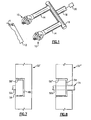
- FIG 1 schematically illustrates selected portions of several gripper assemblies 10 used in an example industrial setting to grip and move a work piece 12 (shown schematically).
- the gripper assemblies 10 may be used in a variety of different configurations from that shown.
- the gripper assemblies 10 are coupled to extended arms 14, which are each secured to a rail 16.
- An adapter arm 18 is secured to the rail 16.
- Figures 2-5 illustrate various views of selected portions of an example gripper assembly 10.
- Figure 2 is a partially exploded view of the gripper assembly 10.
- Figure 3 is a partial view of the gripper assembly 10 without one of the jaws.
- Figure 4 is a sectioned view, and
- Figure 5 is a partial view of the gripper assembly 10 without one of the jaws or a central support.
- the gripper assembly 10 includes an actuator 30, such as a pneumatic or hydraulic actuator, that actuates a piston rod 31 in a known manner to selectively open or close gripper jaws 32a and 32b.
- the actuator 30 includes a housing 34 that contains a piston within a bore (not shown).
- the support 36 includes a hollow central portion 44 (i.e., a guide slot), cam slots 46 that open laterally relative to the length of the hollow central portion 44, and pivot bosses 48 (one shown).
- the piston rod 31 extends within the hollow central portion 44, which functions as a guide slot for guiding movement of the piston rod 31.
- a distal end (relative to the actuator 30) of the piston rod 31 is coupled with a cam head 50.
- Cam pins 52a and 52b are coupled with the cam head 50 and extend outwards in opposite lateral directions from the cam head 50.
- two cam pins 52a and 52b are offset from each other such that the cam pins 52a and 52b are non-coaxial.
- a single cam pin extending in both lateral directions from the cam head 50 or two coaxial cam pins may be used.
- a roller 54 is received on each of the cam pins 52a and 52b.
- the cam pins 52a and 52b and rollers 54 are received into cam slots 56 within each of the jaws 32a and 32b.
- the rollers 54 facilitate movement of the cam pins 52a and 52b through the cam slots 56.
- the fasteners 58 are threaded and mate with threads within the pivot bosses 48.
- the fasteners 58 secure the jaws 32a and 32b to the support 36.
- the fasteners 58 also secure a cover 60 ( Figure 2 ) over each of the jaws 32a and 32b, which retains the roller 54 within the gripper 10 if the rollers 54 are not secured laterally on the cam pins 52a and 52b.
- the pivot bosses 48 extend entirely through each of the openings 59 and the fasteners are 58 are c-clips (not shown) that secure to the respective ends of the pivot bosses 48 to pivotally secure the jaws 32a and 32b on the support 36.
- the gripper assembly 10 does not include the covers 60, and instead utilizes keyed washers 63 (one shown) that fit onto respective pivot bosses 48' to hold the jaws 32a and 32b on the gripper assembly 10.
- Each pivot boss 48' includes flat sides 65a and 65b that correspond to flat sides 67a and 67b of the keyed washer 63.
- the flat sides 65a, 65b, 67a, 67b prevent the keyed washer 63 from rotating once received onto the pivot boss 48'.
- the covers 60 may not be desired if the rollers 54 are laterally secured to the cam pins 52a and 52b.
- the rollers 54 and respective cam pins 52a and 52b may include a tongue-and-groove connection that prevents the rollers 54 from sliding laterally on the cam pins 52a and 52b.
- Other types of connections may also be used to secure the rollers 54 on the cam pins 52a and 52b.
- Figure 8 shows another example of a portion of another version of a gripper jaw 32" that is similar to the jaws 32a and 32b.
- the jaw 32" includes a stepped cam slot 56" that narrows in a step-wise manner through the thickness of the jaw 32".
- the stepped shape allows the jaw 32" to retain the roller 54 and allows the end 71 of the cam pin 52a or 52b to extend entirely through the jaw 32" for the purpose of, for example, sensing movement of the jaw 32" via movement of the cam pin 52a or 52b.
- the actuator 30 of the above example gripper assemblies 10 selectively reciprocates the piston rod 31 to move the cam head 50, and hence the cam pins 52a and 52b.
- the cam slots 46 in the support 36 linearly guide the cam pins 52a and 52b as the cam pins 52a and 52b and respective rollers 54 translate through the cam slots 56 of the jaws 32a and 32b (alternatively slots 56' or 56" of jaws 32' or 32").
- the movement of the cam pins 52a and 52b and rollers 54 through the cam slots 56 of the jaws 32a and 32b causes the jaws 32a and 32b to pivot on the bearing surfaces 61 about the respective pivot bosses 48 between open and closed positions.
- the construction of the gripper 10 provides convenient replacement of the jaws 32a and 32b with different jaws.
- the fasteners 58 are removed. This allows the jaws 32a and 32b to slide off of the cam pins 52a and 52b and rollers 54, and replacement jaws can then be slid onto the cam pins 52a and 52b and rollers 54. If covers 60 are used, removal of the fasteners 58 also allows the covers 60 to slide out from the slots 39a and 39b to access the jaws 32a and 32b.
- the gripper 10 provides such easy replacement of the jaws 32a and 32b.
- the jaws 32a and 32b are supported by the pivot bosses 48 on the outside of the support 36 rather than between sidewall supports as in previously known gripper assemblies.
- the pivot bosses 48 provide a dual function of allowing the jaws 32a and 32b to pivot and securing the jaws 32a and 32b to the support 36. This allows the jaws 32a and 32b to be removed with the removal of fewer components than previous gripper assemblies and provides direct access to the jaws 32a and 32b rather than trapping the jaws between sidewalls as in previous gripper assemblies.
- Figure 9 illustrates an embodiment of a gripper assembly 210 according to the invention that is similar to the gripper assembly 10 except that the gripper assembly 210 includes modified versions of a support 236 and a cam head 250.
- the gripper assembly 210 includes modified versions of a support 236 and a cam head 250.
- components that are substantially similar to the embodiments shown in Figures 2-5 are represented with like numerals.
- Figure 10 illustrates an isolated view of the support 236.
- the support 236 includes a hollow central portion 244 that is laterally open, but does not include the cam slots 46 of the previous example gripper assembly 10.
- the mounting flange 238 includes a first surface 211a and a second surface 21 Ib that is raised relative to the first surface 211a.
- the raised second surface 21 Ib functions as a locator to mount the support 236 in a desired orientation onto a corresponding recessed portion of the actuator 30.
- the support 236 also includes a head 221 (i.e., a collision surface) that may act to stop work pieces inserted between the jaws 32a and 32b, for example.
- a head 221 i.e., a collision surface
- the head 221 spans across a distance 223 ( Figure 11 ) that is greater than a width 225 of the hollow central portion 244. That is, the head 221 is larger than at least the central portion of the support 236.
- the guide channels 203 and 205 receive corresponding guide members 207 and 209 formed on cam head 250.
- the guide channels 203 and 205 may be located on the cam head 250 and the guide members 207 and 209 may be located on the support 236.
- the guide members 207 and 209 interlock with the guide channels 203 and 205 to linearly guide the cam head 250 as the piston rod 31 reciprocates. That is, the guide channels 203 and 205 and the guide members 207 and 209 limit lateral movement of the cam head 250 during reciprocation.
- the cam head 250 includes a curved surface 231 that faces in a direction generally outwards from the actuator 30 and an opposing surface 233 facing into a direction generally toward the actuator 30.
- the curved surface 231 has a curvature that corresponds to a curvature of the curved end 201 of the support 236.
- the combination of the curved surface 231 and the curved end 201 with the gradually shallowing guide channels 203 and 205 reduces the length of the gripper assembly 210, which would otherwise be longer if squared ends were used.
- the gripper assembly 210 also includes a cover 60', similar to the cover 60 in the previous examples except that the cover 60' includes pivot tabs 241 a and 241 b that are slidably received into corresponding slots 239a and 239b of the support 236.
- the pivot tabs 241 a and 241 b allow pivoting of the covers 60' about an axis B when the fasteners 58 are removed to provide access to the jaws 32a and 32b. That is, by pivoting one of the covers 60' outwards from the gripper assembly 210, the jaw 32a is free to slide off of the pivot boss 248 for replacement. Likewise, the other jaw 32b can be removed and replaced by pivoting the other cover 60'.
Landscapes
- Engineering & Computer Science (AREA)
- Mechanical Engineering (AREA)
- Robotics (AREA)
- Manipulator (AREA)
Description
- This invention generally relates to automated handling equipment. More particularly, this invention relates to an actuated gripper device having a central support that guides movement of the actuator and supports at least one gripper jaw.
- Automated handling equipment is typically employed in industrial settings for transferring work pieces between work stations. Typically, the equipment includes an actuated gripper that clamps the work pieces while moving them between the stations. One type of conventional gripper includes an actuator that linearly reciprocates a piston. The piston is coupled to a cam pin that extends outwards in opposite directions from the end of the piston. The respective opposing ends of the cam pin are received through cam slots of two opposed gripper jaws, which are received between two sidewalls that extend from the actuator. Each sidewall includes a pivot pin that extends between the sidewalls and through the gripper jaws to pivotally support the jaws from the sidewalls. A cover is usually secured to the outside of each sidewall with multiple fasteners to prevent the pivot pin from sliding out from between the side walls during use. Typically, the sidewalls also include guide slots that guide the ends of the cam pin as the cam pin slides along the cam slots of the jaws to pivot the jaws about the pivot pins between open and closed jaw positions.
- The jaws of typical grippers are removable and replaceable with different jaws to accommodate work pieces of varying shapes and sizes. For example, jaws having different cam slot lengths and shapes (i.e., slot angles) may be substituted to change the size of the opening between the jaws. One drawback of conventional grippers is that removing the jaws is rather complex and time consuming. For example, in the conventional gripper described above, the multiple fasteners and the pivot pin must be removed. Each jaw must then be disassembled from the cam pin, which may be tedious because the confined space between the side walls. Thus, the conventional gripper construction requires assembly and disassembly of a relatively large number of components within a tight space to replace the jaws. Accordingly, there is a need for a gripper construction that provides more convenient jaw replacement.
-
WO 92/12831 -
US 3570835 discloses a power operated clamping device with a cam actuated pivotally mounted clamp arm. Movement of a piston causes the clamping arm to pivot between an open and a closed position. - An example gripper assembly for providing easy jaw replacement includes:
- a first gripper jaw;
- a second gripper jaw;
- an actuator head moveable along an axis;
- at least one cam pin coupled with the actuator head and operative to move the first gripper jaw in response to movement of the actuator head;
- an actuator operative for moving the actuator head to move the first gripper jaw; and
- a central support that is fixed relative to the actuator, the central support including a guide slot, where one of the actuator head or the guide slot includes a channel and the other of the actuator head or the guide slot includes a guide member extending there from at least partially into the channel and limiting lateral movement of the head during reciprocation.
-
-
Figure 1 illustrates example gripper assemblies for moving work pieces between work stations. -
Figure 2 illustrates a partially exploded view of an example gripper assembly ofFigure 1 . -
Figure 3 illustrates a perspective view of selected portions of the example gripper assembly ofFigure 2 . -
Figure 4 illustrates a cross-sectional view of selected portions of the example gripper assembly ofFigure 2 .Figure 5 illustrates a perspective view of selected portions of the example gripper assembly ofFigure 2 . -
Figure 6 illustrates another embodiment of a gripper assembly. -
Figure 7 illustrates a portion of a modified gripper jaw. -
Figure 8 illustrates a portion of another modified gripper jaw. -
Figure 9 illustrates a gripper assembly according to the invention. -
Figure 10 illustrates an isolated view of a support of the gripper assembly ofFigure 9 . -
Figure 11 illustrates a partial view of the gripper assembly ofFigure 9 , without the gripper jaws. -
Figure 12 illustrates another partial view of the gripper assembly ofFigure 9 , without the gripper jaws.Figure 13 illustrates the gripper assembly ofFigure 9 , with an optional cover. -
Figure 1 schematically illustrates selected portions ofseveral gripper assemblies 10 used in an example industrial setting to grip and move a work piece 12 (shown schematically). Thegripper assemblies 10 may be used in a variety of different configurations from that shown. In this example, thegripper assemblies 10 are coupled to extendedarms 14, which are each secured to arail 16. Anadapter arm 18 is secured to therail 16. Anautomated machine 20, such as a robot, moves theadapter arm 18, the extendedarms 14, and the gripper assemblies 10 to desired positions to retrieve and deposit thework pieces 12, such as between work stations. -
Figures 2-5 illustrate various views of selected portions of anexample gripper assembly 10.Figure 2 is a partially exploded view of thegripper assembly 10.Figure 3 is a partial view of thegripper assembly 10 without one of the jaws.Figure 4 is a sectioned view, andFigure 5 is a partial view of thegripper assembly 10 without one of the jaws or a central support. With reference to these figures, thegripper assembly 10 includes anactuator 30, such as a pneumatic or hydraulic actuator, that actuates apiston rod 31 in a known manner to selectively open orclose gripper jaws actuator 30 includes ahousing 34 that contains a piston within a bore (not shown). - The
gripper assembly 10 includes asupport 36 having aflange 38 and asupport section 40 that extends from theflange 38 generally parallel to thepiston rod 31. In this example, fourfasteners 42 are received through theflange 38 and into thehousing 34 to secure thesupport 36 andactuator 30 together. - The
support 36 includes a hollow central portion 44 (i.e., a guide slot),cam slots 46 that open laterally relative to the length of the hollowcentral portion 44, and pivot bosses 48 (one shown). Thepiston rod 31 extends within the hollowcentral portion 44, which functions as a guide slot for guiding movement of thepiston rod 31. - In this example, the
support 36, including thepivot bosses 48, is an integral, monolithic piece, which may be formed from a single type of material, for example. Thesupport 36 may be machined from a preformed metal blank, cast, or formed in another known manner to produce the illustrated shape or other desired shape. Given this description, one of ordinary skill in the art will recognize other methods of making thesupport 36 to suit their particular needs. - A distal end (relative to the actuator 30) of the
piston rod 31 is coupled with acam head 50.Cam pins cam head 50 and extend outwards in opposite lateral directions from thecam head 50. In the disclosed example, twocam pins cam head 50 or two coaxial cam pins may be used. - Optionally, a
roller 54 is received on each of the cam pins 52a and 52b. The cam pins 52a and 52b androllers 54 are received intocam slots 56 within each of thejaws rollers 54 facilitate movement of the cam pins 52a and 52b through thecam slots 56. - The
jaws respective pivot bosses 48. That is, thepivot bosses 48 are received at least partially intorespective openings 59 through each of thejaws fastener 58 is received though theopening 59 through each of thejaws respective pivot bosses 48 to prevent thejaws pivot bosses 48. - In the illustrated example, the
fasteners 58 are threaded and mate with threads within thepivot bosses 48. Thefasteners 58 secure thejaws support 36. In this example, there is some play between thepivot bosses 48 and theopenings 59 such that thejaws respective pivot bosses 48. That is, thepivot bosses 48 provide abearing surface 61 for rotation of thejaws - The
fasteners 58 also secure a cover 60 (Figure 2 ) over each of thejaws roller 54 within thegripper 10 if therollers 54 are not secured laterally on the cam pins 52a and 52b. Alternatively, thepivot bosses 48 extend entirely through each of theopenings 59 and the fasteners are 58 are c-clips (not shown) that secure to the respective ends of thepivot bosses 48 to pivotally secure thejaws support 36. - In this example, the
flange 38 of thesupport 36 also includes aslot 39a in the shape of a dovetail, for example, that receives atab 41 a of thecover 60. Anotherslot 39b supports anothertab 41 b on thecover 60. Thetabs slots gripper assembly 10 such thatcover openings 43 align withrespective pivot bosses 48 for receiving thefasteners 58. - In another example shown in
Figure 6 , thegripper assembly 10 does not include thecovers 60, and instead utilizes keyed washers 63 (one shown) that fit onto respective pivot bosses 48' to hold thejaws gripper assembly 10. Each pivot boss 48' includesflat sides 65a and 65b that correspond toflat sides 67a and 67b of the keyedwasher 63. Theflat sides washer 63 from rotating once received onto the pivot boss 48'. - In one example, the
covers 60 may not be desired if therollers 54 are laterally secured to the cam pins 52a and 52b. For example, therollers 54 and respective cam pins 52a and 52b may include a tongue-and-groove connection that prevents therollers 54 from sliding laterally on the cam pins 52a and 52b. Other types of connections may also be used to secure therollers 54 on the cam pins 52a and 52b. - In another example, the
covers 60 may not be needed to retain therollers 54 on therespective cam pins gripper jaws Figure 7 shows one example of a portion of another version of a gripper jaw 32' that is similar to thejaws cam slot 56' that extends partially through the thickness of the jaw 32', rather than entirely through ascam slot 56 ofjaws inner wall 69 retains theroller 54 on thecam pin 52a. -
Figure 8 shows another example of a portion of another version of a gripper jaw 32" that is similar to thejaws cam slot 56" that narrows in a step-wise manner through the thickness of the jaw 32". The stepped shape allows the jaw 32" to retain theroller 54 and allows theend 71 of thecam pin cam pin - In operation, the
actuator 30 of the aboveexample gripper assemblies 10 selectively reciprocates thepiston rod 31 to move thecam head 50, and hence the cam pins 52a and 52b. Thecam slots 46 in thesupport 36 linearly guide the cam pins 52a and 52b as the cam pins 52a and 52b andrespective rollers 54 translate through thecam slots 56 of thejaws slots rollers 54 through thecam slots 56 of thejaws jaws respective pivot bosses 48 between open and closed positions. - In the disclosed example, the construction of the
gripper 10 provides convenient replacement of thejaws jaws fasteners 58 are removed. This allows thejaws rollers 54, and replacement jaws can then be slid onto the cam pins 52a and 52b androllers 54. If covers 60 are used, removal of thefasteners 58 also allows thecovers 60 to slide out from theslots jaws - It is the construction of the
gripper 10 that provides such easy replacement of thejaws jaws pivot bosses 48 on the outside of thesupport 36 rather than between sidewall supports as in previously known gripper assemblies. Thus, thepivot bosses 48 provide a dual function of allowing thejaws jaws support 36. This allows thejaws jaws -
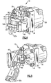
Figure 9 illustrates an embodiment of agripper assembly 210 according to the invention that is similar to thegripper assembly 10 except that thegripper assembly 210 includes modified versions of asupport 236 and acam head 250. In this example, components that are substantially similar to the embodiments shown inFigures 2-5 are represented with like numerals.Figure 10 illustrates an isolated view of thesupport 236. In this example, thesupport 236 includes a hollowcentral portion 244 that is laterally open, but does not include thecam slots 46 of the previousexample gripper assembly 10. - The hollow
central portion 244 extends from a mountingflange 238 to acurved end 201. The hollowcentral portion 244 includesguide channels flange 238 andcurved end 201. In this example, theguide channels guide channels curved end 201. It is to be understood that other example supports may include only a single guide channel, and the channel or channels may also be of uniform depth. - The
support 236 also includespivot bosses 248 having outer bearingsurfaces 261 for pivotally supportingjaws pivot bosses 248 andsupport 236 form an integral, monolithic piece. For example, thesupport 236 may be machined from a pre-formed metal blank, cast, or formed in another known manner to produce the illustrated shape or other desired shape. - The mounting
flange 238 includes afirst surface 211a and a second surface 21 Ib that is raised relative to thefirst surface 211a. The raised second surface 21 Ib functions as a locator to mount thesupport 236 in a desired orientation onto a corresponding recessed portion of theactuator 30. - The
support 236 also includes a head 221 (i.e., a collision surface) that may act to stop work pieces inserted between thejaws head 221 spans across a distance 223 (Figure 11 ) that is greater than awidth 225 of the hollowcentral portion 244. That is, thehead 221 is larger than at least the central portion of thesupport 236. - Referring to
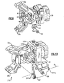
Figure 11 (cam head 250 retracted) andFigure 12 (cam head 250 extended), theguide channels corresponding guide members cam head 250. Alternatively, theguide channels cam head 250 and theguide members support 236. Theguide members guide channels cam head 250 as thepiston rod 31 reciprocates. That is, theguide channels guide members cam head 250 during reciprocation. - The
cam head 250 includes acurved surface 231 that faces in a direction generally outwards from theactuator 30 and an opposingsurface 233 facing into a direction generally toward theactuator 30. In the illustrated example, thecurved surface 231 has a curvature that corresponds to a curvature of thecurved end 201 of thesupport 236. The combination of thecurved surface 231 and thecurved end 201 with the gradually shallowingguide channels gripper assembly 210, which would otherwise be longer if squared ends were used. - Optionally, as shown in
Figure 13 , thegripper assembly 210 also includes a cover 60', similar to thecover 60 in the previous examples except that the cover 60' includespivot tabs slots 239a and 239b of thesupport 236. Thepivot tabs fasteners 58 are removed to provide access to thejaws gripper assembly 210, thejaw 32a is free to slide off of thepivot boss 248 for replacement. Likewise, theother jaw 32b can be removed and replaced by pivoting the other cover 60'. - Although a combination of features is shown in the illustrated examples, not all of them need to be combined to realize the benefits of various embodiments of this disclosure. In other words, a system designed according to an embodiment of this disclosure will not necessarily include all of the features shown in any one of the Figures or all of the portions schematically shown in the Figures. Moreover, selected features of one example embodiment may be combined with selected features of other example embodiments.
- The preceding description is exemplary rather than limiting in nature. Variations and modifications to the disclosed examples may become apparent to those skilled in the art that do not necessarily depart from the essence of this disclosure.
Claims (11)
- A gripper assembly (210) comprising:a first gripper jaw (32a);a second gripper jaw (32b)an actuator head (250) moveable along an axis;cam pins (52a, 52b) coupled with the actuator head (250) and extending outwards in opposite lateral directions from the actuator head (250), and operative to move the first gripper jaw (32a) in response to movement of the actuator head (250);an actuator (30) operative for moving the actuator head (250) to move the first and second gripper jaws (32a, 32b); anda central support (236) that is fixed relative to the actuator (30), the central support (236) including a guide slot (244) that receives the actuator head (250), where one of the actuator head (250) or the guide slot (244) includes a channel (203) and the other of the actuator head (250) or the guide slot (244) includes a guide member (207) extending there from at least partially into the channel (203) and limiting lateral movement of the head (250) during reciprocation.
- The gripper assembly (210) as recited in claim 1, wherein the one of the actuator head (250) or the guide slot (244) that includes the channel (203) further includes another channel (205), and the other of the actuator head (250) or the guide slot (244) further includes another guide member (209) extending there from at least partially into the other channel (205), and optionally wherein the channels (203, 205) open in opposite directions, or alternatively wherein the guide members (207, 209) extend in opposite directions.
- The gripper assembly (210) as recited in claim 1, wherein the guide member (207) protrudes from a surface of the actuator head (250) or the guide slot (244), where a nominal height that the guide member (207) protrudes gradually increases along the surface.
- The gripper assembly (210) as recited in claim 1, wherein the actuator head (250) includes a first side (233) that faces in a direction toward the actuator (30) and a second side (231) that faces in an opposite direction, where the second side (231) comprises a curved surface, and optionally wherein the guide slot (244) includes a first end near the actuator (30) and a second end (201) distal from the actuator (30), and the second end (201) includes a corresponding curved surface.
- The gripper assembly (210) as recited in claim 1, wherein the central support (236) includes bearing surfaces (261) that pivotally support the first gripper jaw (32a) and the second gripper jaw (32b).
- The gripper assembly (210) as recited in claim 1, wherein the channel (203) comprises a non-uniform depth.
- The gripper assembly (210) as recited in claim 1, wherein the central support (236) includes a first end near the actuator (30) and a second end distal from the actuator (30), the second end including a collision surface (221) that spans across a distance (223) that is greater than a width (225) of the guide slot (244) in a direction perpendicular to movement of the actuator head (250).
- The gripper assembly (210) as recited in claim 1, wherein the central support (244) includes a first end near the actuator (30) and a second end (201) distal from the actuator (30), the first end including a mount section (238) having a first planar surface (211a) and a second planar surface (211 b) raised relative to the first planar surface (211 a) for locating the central support (236) on the actuator (30).
- The gripper assembly (210) as recited in claim 1, wherein the first gripper jaw (32a) and the second gripper jaw (32b) each include a stepped cam slot (56").
- The gripper assembly (210) as recited in claim 1, wherein the first jaw (32a) and the second jaw (32b) are situated on opposite sides of the guide slot (244).
- The gripper assembly (210) as recited in claim 1, wherein the support (236) includes first and second pivot bosses (248) on opposite sides of the central support (236) where the central support (236), including the pivot bosses (248), is an integral, monolithic piece, the first jaw (32a) is received onto the first pivot boss (248), and the second jaw (32b) is received onto the second pivot boss (248).
Applications Claiming Priority (3)
| Application Number | Priority Date | Filing Date | Title |
|---|---|---|---|
| US83153106P | 2006-07-18 | 2006-07-18 | |
| US11/786,944 US7837247B2 (en) | 2006-07-18 | 2007-04-13 | Gripper with central support |
| PCT/US2007/067874 WO2008011209A1 (en) | 2006-07-18 | 2007-05-01 | Gripper with central support |
Publications (2)
| Publication Number | Publication Date |
|---|---|
| EP2040887A1 EP2040887A1 (en) | 2009-04-01 |
| EP2040887B1 true EP2040887B1 (en) | 2012-09-05 |
Family
ID=38477272
Family Applications (1)
| Application Number | Title | Priority Date | Filing Date |
|---|---|---|---|
| EP07761637A Active EP2040887B1 (en) | 2006-07-18 | 2007-05-01 | Gripper with central support |
Country Status (4)
| Country | Link |
|---|---|
| US (3) | US7837247B2 (en) |
| EP (1) | EP2040887B1 (en) |
| JP (1) | JP2009543707A (en) |
| WO (1) | WO2008011209A1 (en) |
Families Citing this family (32)
| Publication number | Priority date | Publication date | Assignee | Title |
|---|---|---|---|---|
| US7837247B2 (en) * | 2006-07-18 | 2010-11-23 | Syron Engineering & Manufacturing, Llc | Gripper with central support |
| USD604752S1 (en) * | 2007-05-16 | 2009-11-24 | Schunk Gmbh & Co. Kg Spann- Und Greiftechnik | Gripping device |
| JP2009107076A (en) | 2007-10-31 | 2009-05-21 | Smc Corp | Clamping device |
| JP4950123B2 (en) * | 2008-05-21 | 2012-06-13 | シーケーディ株式会社 | Clamping device |
| US8271892B2 (en) | 2008-07-02 | 2012-09-18 | Icharts, Inc. | Creation, sharing and embedding of interactive charts |
| US8520000B2 (en) | 2008-07-02 | 2013-08-27 | Icharts, Inc. | Creation, sharing and embedding of interactive charts |
| TWI350811B (en) * | 2008-07-11 | 2011-10-21 | King Yuan Electronics Co Ltd | Segregating apparatus |
| US9679499B2 (en) * | 2008-09-15 | 2017-06-13 | Immersion Medical, Inc. | Systems and methods for sensing hand motion by measuring remote displacement |
| USD651625S1 (en) * | 2010-03-03 | 2012-01-03 | Yuyama Mfg. Co., Ltd. | Gripping device |
| US8595911B2 (en) * | 2010-03-30 | 2013-12-03 | Honda Motor Co., Ltd. | Extraction device for removing a vehicle fastener |
| ITMI20100680A1 (en) * | 2010-04-21 | 2011-10-22 | Luben S R L | GRIPPING PLIER |
| USD651225S1 (en) * | 2011-02-03 | 2011-12-27 | Yuyama Mfg. Co., Ltd. | Gripping apparatus |
| USD651626S1 (en) * | 2011-02-03 | 2012-01-03 | Yuyama Mfg. Co., Ltd. | Gripping apparatus |
| DE102012200073A1 (en) * | 2012-01-04 | 2013-07-04 | Karl Storz Gmbh & Co. Kg | Medical instrument |
| FR2989297B1 (en) * | 2012-04-12 | 2015-03-13 | Christophe Boiteux | DEVICE FOR CLAMPING A PIECE ON A TOOL |
| TWI577508B (en) | 2012-08-07 | 2017-04-11 | Smc股份有限公司 | Clamp apparatus |
| JP5559287B2 (en) * | 2012-11-07 | 2014-07-23 | ファナック株式会社 | Robot hand handling workpieces in high temperature areas |
| JP5821134B2 (en) * | 2013-01-28 | 2015-11-24 | Smc株式会社 | Clamping device |
| JP5942126B2 (en) * | 2013-07-18 | 2016-06-29 | Smc株式会社 | Clamping device |
| JP5917471B2 (en) * | 2013-10-09 | 2016-05-18 | Ckd株式会社 | Clamping device |
| US9665654B2 (en) | 2015-04-30 | 2017-05-30 | Icharts, Inc. | Secure connections in an interactive analytic visualization infrastructure |
| CN105110025A (en) * | 2015-09-10 | 2015-12-02 | 深圳博美德机器人有限公司 | Robot palletizer fixture |
| USD781122S1 (en) * | 2015-09-15 | 2017-03-14 | Delaware Capital Formation, Inc. | Upper gripper jaw |
| US9492929B1 (en) * | 2015-11-04 | 2016-11-15 | Google Inc. | Flat gripper actuator |
| DE202016008622U1 (en) * | 2015-12-23 | 2018-09-17 | Phd, Inc. | Mechanism with a sensor for detecting the presence of a plate and a double layer for grippers |
| CN105751235A (en) * | 2016-05-17 | 2016-07-13 | 陈旭芳 | Mechanical hand clamp and intelligent clamp system |
| US10689240B1 (en) | 2017-06-07 | 2020-06-23 | Cornelius, Inc. | Automated beverage dispensing machines |
| CN111491761B (en) * | 2017-12-22 | 2022-04-05 | 布奇自动化公司 | Adjustable bar guiding device |
| US10549431B2 (en) * | 2018-06-15 | 2020-02-04 | Delaware Capital Formation, Inc. | Gripper with a trident body section |
| US10994423B2 (en) * | 2018-06-15 | 2021-05-04 | Delaware Capital Formation, Inc. | Gripper with a trident body section |
| JP7052896B2 (en) * | 2021-03-04 | 2022-04-12 | 日本精工株式会社 | Gripping device |
| CN114335679A (en) * | 2021-12-30 | 2022-04-12 | 苏州世纪福智能装备股份有限公司 | Manipulator end effector suitable for lithium batteries with different shapes and thicknesses |
Family Cites Families (21)
| Publication number | Priority date | Publication date | Assignee | Title |
|---|---|---|---|---|
| US886003A (en) | 1907-08-08 | 1908-04-28 | Howard Wattles V | Gaff-hook. |
| US3147004A (en) | 1959-02-02 | 1964-09-01 | Leland F Blatt | Work securing clamp |
| US3362703A (en) * | 1966-06-23 | 1968-01-09 | Leland F. Blatt | Cam wedge power clamp |
| US3570835A (en) | 1968-10-08 | 1971-03-16 | Dover Corp | Power operated clamping device |
| US4537389A (en) * | 1983-12-27 | 1985-08-27 | Universal Automatic Corporation | Machine tool fixture |
| US5085480A (en) | 1990-04-09 | 1992-02-04 | Jackson Donald T | Cam operated workpiece engaging apparatus |
| US5152568A (en) | 1991-01-24 | 1992-10-06 | Blatt John A | Extendible gripper |
| US5125708A (en) * | 1991-05-20 | 1992-06-30 | Nicky Borcea | Wedge gripper |
| DE4236670A1 (en) | 1992-10-30 | 1994-05-05 | Sta Co Mettallerzeugnisse Gmbh | Clamping device |
| US5284375A (en) * | 1993-03-12 | 1994-02-08 | Ingersoll-Rand Company | Single actuation rod gripping mechanism |
| US5516173A (en) | 1993-03-15 | 1996-05-14 | Btm Corporation | Gripper |
| US5460358A (en) * | 1993-11-29 | 1995-10-24 | Sendoykas; Jack J. | Power clamp |
| US6115898A (en) | 1995-06-06 | 2000-09-12 | Btm Corporation | Force multiplying apparatus for clamping a workpiece and forming a joint therein |
| EP0935516B1 (en) | 1996-10-07 | 2004-01-21 | PHD, Inc. | Modular stamped parts transfer gripper |
| US5853211A (en) * | 1997-01-10 | 1998-12-29 | Btm Corporation | Universal gripper |
| US6079896A (en) | 1998-01-07 | 2000-06-27 | Isi Norgren, Inc. | Clamp with improved internal cam action |
| US6634630B2 (en) * | 1999-06-01 | 2003-10-21 | Aladdin Engineering & Manufacturing | Clamping and lifting mechanism |
| US6530616B1 (en) * | 2000-06-27 | 2003-03-11 | Phd, Inc. | Continuity switch for parts grippers |
| US6530615B2 (en) | 2001-01-17 | 2003-03-11 | Syron Engineering & Mfg., Llc | Workpiece gripper |
| US6641189B2 (en) * | 2001-03-16 | 2003-11-04 | Phd, Inc. | Article sensor assembly |
| US7837247B2 (en) * | 2006-07-18 | 2010-11-23 | Syron Engineering & Manufacturing, Llc | Gripper with central support |
-
2007
- 2007-04-13 US US11/786,944 patent/US7837247B2/en active Active
- 2007-05-01 WO PCT/US2007/067874 patent/WO2008011209A1/en not_active Ceased
- 2007-05-01 EP EP07761637A patent/EP2040887B1/en active Active
- 2007-05-01 JP JP2009520868A patent/JP2009543707A/en active Pending
-
2010
- 2010-09-24 US US12/890,033 patent/US8070202B2/en active Active
-
2011
- 2011-11-07 US US13/290,394 patent/US8297673B2/en active Active
Also Published As
| Publication number | Publication date |
|---|---|
| US20120049553A1 (en) | 2012-03-01 |
| US8070202B2 (en) | 2011-12-06 |
| US7837247B2 (en) | 2010-11-23 |
| US8297673B2 (en) | 2012-10-30 |
| EP2040887A1 (en) | 2009-04-01 |
| US20110018292A1 (en) | 2011-01-27 |
| WO2008011209A1 (en) | 2008-01-24 |
| JP2009543707A (en) | 2009-12-10 |
| US20080018124A1 (en) | 2008-01-24 |
Similar Documents
| Publication | Publication Date | Title |
|---|---|---|
| EP2040887B1 (en) | Gripper with central support | |
| CN100368110C (en) | Bending machine die provided with a vise for clamping an elongated workpiece to be bent | |
| US6530615B2 (en) | Workpiece gripper | |
| US20040070130A1 (en) | Locating assembly having an extendable clamping finger | |
| US7845698B2 (en) | Gripper with adjustable bumper stops | |
| EP1830022B1 (en) | Controlled latch clamp | |
| US9901968B2 (en) | Pipe bend die unit, and pipe bending apparatus having the unit | |
| EP2983844B1 (en) | Punch apparatus | |
| KR20190142259A (en) | Gripper | |
| EP1004410A2 (en) | Adjustable stoppers for limiting the opening angle of a gripper | |
| US8585113B2 (en) | Parallel pneumatic gripper | |
| KR102060867B1 (en) | O-ring mounting device and method | |
| JP2010537833A (en) | High precision guiding device in machines for machining cylindrical components | |
| US6361095B1 (en) | Adjustable stroke gripper assembly | |
| CN113795340A (en) | Sheet metal bending machine | |
| JP5276665B2 (en) | Die press assembly for powder press | |
| US12311513B2 (en) | Ram guide for a crimper | |
| CN214349019U (en) | Automatic punching, hole pulling and flat head device for stainless steel pipe | |
| EP2241402B1 (en) | Device for locking workpieces | |
| EP2484459A1 (en) | Clamping method and device for carrying out the same | |
| CN212559126U (en) | Hoisting tool | |
| KR100779655B1 (en) | Draw-out device for easy disassembly and assembly of winding reel segment of cold rolled steel | |
| KR101639193B1 (en) | Auto tooling machine | |
| CN121733216A (en) | Bushing pressing device | |
| CN118493440A (en) | Terminal clamping jaw of intelligent equipment |
Legal Events
| Date | Code | Title | Description |
|---|---|---|---|
| PUAI | Public reference made under article 153(3) epc to a published international application that has entered the european phase |
Free format text: ORIGINAL CODE: 0009012 |
|
| 17P | Request for examination filed |
Effective date: 20090108 |
|
| AK | Designated contracting states |
Kind code of ref document: A1 Designated state(s): AT BE BG CH CY CZ DE DK EE ES FI FR GB GR HU IE IS IT LI LT LU LV MC MT NL PL PT RO SE SI SK TR |
|
| AX | Request for extension of the european patent |
Extension state: AL BA HR MK RS |
|
| 17Q | First examination report despatched |
Effective date: 20100802 |
|
| GRAP | Despatch of communication of intention to grant a patent |
Free format text: ORIGINAL CODE: EPIDOSNIGR1 |
|
| GRAS | Grant fee paid |
Free format text: ORIGINAL CODE: EPIDOSNIGR3 |
|
| GRAA | (expected) grant |
Free format text: ORIGINAL CODE: 0009210 |
|
| DAX | Request for extension of the european patent (deleted) | ||
| AK | Designated contracting states |
Kind code of ref document: B1 Designated state(s): AT BE BG CH CY CZ DE DK EE ES FI FR GB GR HU IE IS IT LI LT LU LV MC MT NL PL PT RO SE SI SK TR |
|
| REG | Reference to a national code |
Ref country code: GB Ref legal event code: FG4D |
|
| REG | Reference to a national code |
Ref country code: CH Ref legal event code: EP |
|
| REG | Reference to a national code |
Ref country code: AT Ref legal event code: REF Ref document number: 573870 Country of ref document: AT Kind code of ref document: T Effective date: 20120915 |
|
| REG | Reference to a national code |
Ref country code: IE Ref legal event code: FG4D |
|
| REG | Reference to a national code |
Ref country code: DE Ref legal event code: R096 Ref document number: 602007025295 Country of ref document: DE Effective date: 20121031 |
|
| REG | Reference to a national code |
Ref country code: AT Ref legal event code: MK05 Ref document number: 573870 Country of ref document: AT Kind code of ref document: T Effective date: 20120905 |
|
| REG | Reference to a national code |
Ref country code: NL Ref legal event code: VDEP Effective date: 20120905 |
|
| PG25 | Lapsed in a contracting state [announced via postgrant information from national office to epo] |
Ref country code: CY Free format text: LAPSE BECAUSE OF FAILURE TO SUBMIT A TRANSLATION OF THE DESCRIPTION OR TO PAY THE FEE WITHIN THE PRESCRIBED TIME-LIMIT Effective date: 20120905 Ref country code: LT Free format text: LAPSE BECAUSE OF FAILURE TO SUBMIT A TRANSLATION OF THE DESCRIPTION OR TO PAY THE FEE WITHIN THE PRESCRIBED TIME-LIMIT Effective date: 20120905 Ref country code: AT Free format text: LAPSE BECAUSE OF FAILURE TO SUBMIT A TRANSLATION OF THE DESCRIPTION OR TO PAY THE FEE WITHIN THE PRESCRIBED TIME-LIMIT Effective date: 20120905 Ref country code: FI Free format text: LAPSE BECAUSE OF FAILURE TO SUBMIT A TRANSLATION OF THE DESCRIPTION OR TO PAY THE FEE WITHIN THE PRESCRIBED TIME-LIMIT Effective date: 20120905 |
|
| REG | Reference to a national code |
Ref country code: LT Ref legal event code: MG4D Effective date: 20120905 |
|
| PG25 | Lapsed in a contracting state [announced via postgrant information from national office to epo] |
Ref country code: LV Free format text: LAPSE BECAUSE OF FAILURE TO SUBMIT A TRANSLATION OF THE DESCRIPTION OR TO PAY THE FEE WITHIN THE PRESCRIBED TIME-LIMIT Effective date: 20120905 Ref country code: SE Free format text: LAPSE BECAUSE OF FAILURE TO SUBMIT A TRANSLATION OF THE DESCRIPTION OR TO PAY THE FEE WITHIN THE PRESCRIBED TIME-LIMIT Effective date: 20120905 Ref country code: SI Free format text: LAPSE BECAUSE OF FAILURE TO SUBMIT A TRANSLATION OF THE DESCRIPTION OR TO PAY THE FEE WITHIN THE PRESCRIBED TIME-LIMIT Effective date: 20120905 Ref country code: GR Free format text: LAPSE BECAUSE OF FAILURE TO SUBMIT A TRANSLATION OF THE DESCRIPTION OR TO PAY THE FEE WITHIN THE PRESCRIBED TIME-LIMIT Effective date: 20121206 |
|
| PG25 | Lapsed in a contracting state [announced via postgrant information from national office to epo] |
Ref country code: ES Free format text: LAPSE BECAUSE OF FAILURE TO SUBMIT A TRANSLATION OF THE DESCRIPTION OR TO PAY THE FEE WITHIN THE PRESCRIBED TIME-LIMIT Effective date: 20121216 Ref country code: EE Free format text: LAPSE BECAUSE OF FAILURE TO SUBMIT A TRANSLATION OF THE DESCRIPTION OR TO PAY THE FEE WITHIN THE PRESCRIBED TIME-LIMIT Effective date: 20120905 Ref country code: CZ Free format text: LAPSE BECAUSE OF FAILURE TO SUBMIT A TRANSLATION OF THE DESCRIPTION OR TO PAY THE FEE WITHIN THE PRESCRIBED TIME-LIMIT Effective date: 20120905 Ref country code: BE Free format text: LAPSE BECAUSE OF FAILURE TO SUBMIT A TRANSLATION OF THE DESCRIPTION OR TO PAY THE FEE WITHIN THE PRESCRIBED TIME-LIMIT Effective date: 20120905 Ref country code: RO Free format text: LAPSE BECAUSE OF FAILURE TO SUBMIT A TRANSLATION OF THE DESCRIPTION OR TO PAY THE FEE WITHIN THE PRESCRIBED TIME-LIMIT Effective date: 20120905 Ref country code: NL Free format text: LAPSE BECAUSE OF FAILURE TO SUBMIT A TRANSLATION OF THE DESCRIPTION OR TO PAY THE FEE WITHIN THE PRESCRIBED TIME-LIMIT Effective date: 20120905 Ref country code: IS Free format text: LAPSE BECAUSE OF FAILURE TO SUBMIT A TRANSLATION OF THE DESCRIPTION OR TO PAY THE FEE WITHIN THE PRESCRIBED TIME-LIMIT Effective date: 20130105 |
|
| PG25 | Lapsed in a contracting state [announced via postgrant information from national office to epo] |
Ref country code: PT Free format text: LAPSE BECAUSE OF FAILURE TO SUBMIT A TRANSLATION OF THE DESCRIPTION OR TO PAY THE FEE WITHIN THE PRESCRIBED TIME-LIMIT Effective date: 20130107 Ref country code: SK Free format text: LAPSE BECAUSE OF FAILURE TO SUBMIT A TRANSLATION OF THE DESCRIPTION OR TO PAY THE FEE WITHIN THE PRESCRIBED TIME-LIMIT Effective date: 20120905 Ref country code: PL Free format text: LAPSE BECAUSE OF FAILURE TO SUBMIT A TRANSLATION OF THE DESCRIPTION OR TO PAY THE FEE WITHIN THE PRESCRIBED TIME-LIMIT Effective date: 20120905 |
|
| PLBE | No opposition filed within time limit |
Free format text: ORIGINAL CODE: 0009261 |
|
| STAA | Information on the status of an ep patent application or granted ep patent |
Free format text: STATUS: NO OPPOSITION FILED WITHIN TIME LIMIT |
|
| PG25 | Lapsed in a contracting state [announced via postgrant information from national office to epo] |
Ref country code: BG Free format text: LAPSE BECAUSE OF FAILURE TO SUBMIT A TRANSLATION OF THE DESCRIPTION OR TO PAY THE FEE WITHIN THE PRESCRIBED TIME-LIMIT Effective date: 20121205 Ref country code: DK Free format text: LAPSE BECAUSE OF FAILURE TO SUBMIT A TRANSLATION OF THE DESCRIPTION OR TO PAY THE FEE WITHIN THE PRESCRIBED TIME-LIMIT Effective date: 20120905 |
|
| 26N | No opposition filed |
Effective date: 20130606 |
|
| PG25 | Lapsed in a contracting state [announced via postgrant information from national office to epo] |
Ref country code: IT Free format text: LAPSE BECAUSE OF FAILURE TO SUBMIT A TRANSLATION OF THE DESCRIPTION OR TO PAY THE FEE WITHIN THE PRESCRIBED TIME-LIMIT Effective date: 20120905 |
|
| REG | Reference to a national code |
Ref country code: DE Ref legal event code: R097 Ref document number: 602007025295 Country of ref document: DE Effective date: 20130606 |
|
| PG25 | Lapsed in a contracting state [announced via postgrant information from national office to epo] |
Ref country code: MC Free format text: LAPSE BECAUSE OF FAILURE TO SUBMIT A TRANSLATION OF THE DESCRIPTION OR TO PAY THE FEE WITHIN THE PRESCRIBED TIME-LIMIT Effective date: 20120905 |
|
| REG | Reference to a national code |
Ref country code: CH Ref legal event code: PL |
|
| PG25 | Lapsed in a contracting state [announced via postgrant information from national office to epo] |
Ref country code: LI Free format text: LAPSE BECAUSE OF NON-PAYMENT OF DUE FEES Effective date: 20130531 Ref country code: CH Free format text: LAPSE BECAUSE OF NON-PAYMENT OF DUE FEES Effective date: 20130531 |
|
| REG | Reference to a national code |
Ref country code: IE Ref legal event code: MM4A |
|
| PG25 | Lapsed in a contracting state [announced via postgrant information from national office to epo] |
Ref country code: IE Free format text: LAPSE BECAUSE OF NON-PAYMENT OF DUE FEES Effective date: 20130501 |
|
| PG25 | Lapsed in a contracting state [announced via postgrant information from national office to epo] |
Ref country code: MT Free format text: LAPSE BECAUSE OF FAILURE TO SUBMIT A TRANSLATION OF THE DESCRIPTION OR TO PAY THE FEE WITHIN THE PRESCRIBED TIME-LIMIT Effective date: 20120905 |
|
| PG25 | Lapsed in a contracting state [announced via postgrant information from national office to epo] |
Ref country code: TR Free format text: LAPSE BECAUSE OF FAILURE TO SUBMIT A TRANSLATION OF THE DESCRIPTION OR TO PAY THE FEE WITHIN THE PRESCRIBED TIME-LIMIT Effective date: 20120905 |
|
| PG25 | Lapsed in a contracting state [announced via postgrant information from national office to epo] |
Ref country code: LU Free format text: LAPSE BECAUSE OF NON-PAYMENT OF DUE FEES Effective date: 20130501 Ref country code: HU Free format text: LAPSE BECAUSE OF FAILURE TO SUBMIT A TRANSLATION OF THE DESCRIPTION OR TO PAY THE FEE WITHIN THE PRESCRIBED TIME-LIMIT; INVALID AB INITIO Effective date: 20070501 |
|
| REG | Reference to a national code |
Ref country code: FR Ref legal event code: PLFP Year of fee payment: 10 |
|
| REG | Reference to a national code |
Ref country code: FR Ref legal event code: PLFP Year of fee payment: 11 |
|
| REG | Reference to a national code |
Ref country code: FR Ref legal event code: PLFP Year of fee payment: 12 |
|
| REG | Reference to a national code |
Ref country code: DE Ref legal event code: R082 Ref document number: 602007025295 Country of ref document: DE Representative=s name: FLEUCHAUS & GALLO PARTNERSCHAFT MBB PATENTANWA, DE Ref country code: DE Ref legal event code: R082 Ref document number: 602007025295 Country of ref document: DE Ref country code: DE Ref legal event code: R082 Ref document number: 602007025295 Country of ref document: DE Representative=s name: FLEUCHAUS & GALLO PARTNERSCHAFT MBB, DE |
|
| REG | Reference to a national code |
Ref country code: DE Ref legal event code: R082 Ref document number: 602007025295 Country of ref document: DE Representative=s name: FLEUCHAUS & GALLO PARTNERSCHAFT MBB PATENTANWA, DE |
|
| PGFP | Annual fee paid to national office [announced via postgrant information from national office to epo] |
Ref country code: FR Payment date: 20180522 Year of fee payment: 12 |
|
| PGFP | Annual fee paid to national office [announced via postgrant information from national office to epo] |
Ref country code: GB Payment date: 20180404 Year of fee payment: 12 |
|
| GBPC | Gb: european patent ceased through non-payment of renewal fee |
Effective date: 20190501 |
|
| PG25 | Lapsed in a contracting state [announced via postgrant information from national office to epo] |
Ref country code: GB Free format text: LAPSE BECAUSE OF NON-PAYMENT OF DUE FEES Effective date: 20190501 |
|
| PG25 | Lapsed in a contracting state [announced via postgrant information from national office to epo] |
Ref country code: FR Free format text: LAPSE BECAUSE OF NON-PAYMENT OF DUE FEES Effective date: 20190531 |
|
| PGFP | Annual fee paid to national office [announced via postgrant information from national office to epo] |
Ref country code: DE Payment date: 20250521 Year of fee payment: 19 |