EP2040774B1 - Ensemble de pompe mammaire - Google Patents
Ensemble de pompe mammaire Download PDFInfo
- Publication number
- EP2040774B1 EP2040774B1 EP07763937.5A EP07763937A EP2040774B1 EP 2040774 B1 EP2040774 B1 EP 2040774B1 EP 07763937 A EP07763937 A EP 07763937A EP 2040774 B1 EP2040774 B1 EP 2040774B1
- Authority
- EP
- European Patent Office
- Prior art keywords
- unit
- suction pump
- breast shield
- breast
- breastpump
- Prior art date
- Legal status (The legal status is an assumption and is not a legal conclusion. Google has not performed a legal analysis and makes no representation as to the accuracy of the status listed.)
- Active
Links
- 210000000481 breast Anatomy 0.000 claims description 105
- 238000005086 pumping Methods 0.000 claims description 29
- 230000008054 signal transmission Effects 0.000 claims description 26
- 235000013336 milk Nutrition 0.000 claims description 13
- 239000008267 milk Substances 0.000 claims description 13
- 210000004080 milk Anatomy 0.000 claims description 13
- 230000008878 coupling Effects 0.000 claims description 9
- 238000010168 coupling process Methods 0.000 claims description 9
- 238000005859 coupling reaction Methods 0.000 claims description 9
- 238000000034 method Methods 0.000 claims description 8
- 235000020256 human milk Nutrition 0.000 claims description 6
- 230000005540 biological transmission Effects 0.000 claims description 5
- 238000005259 measurement Methods 0.000 claims description 3
- 230000003287 optical effect Effects 0.000 claims description 3
- 230000006854 communication Effects 0.000 description 10
- 238000004891 communication Methods 0.000 description 10
- 210000000038 chest Anatomy 0.000 description 7
- NMFHJNAPXOMSRX-PUPDPRJKSA-N [(1r)-3-(3,4-dimethoxyphenyl)-1-[3-(2-morpholin-4-ylethoxy)phenyl]propyl] (2s)-1-[(2s)-2-(3,4,5-trimethoxyphenyl)butanoyl]piperidine-2-carboxylate Chemical compound C([C@@H](OC(=O)[C@@H]1CCCCN1C(=O)[C@@H](CC)C=1C=C(OC)C(OC)=C(OC)C=1)C=1C=C(OCCN2CCOCC2)C=CC=1)CC1=CC=C(OC)C(OC)=C1 NMFHJNAPXOMSRX-PUPDPRJKSA-N 0.000 description 4
- 230000006870 function Effects 0.000 description 4
- 230000007175 bidirectional communication Effects 0.000 description 3
- 238000012545 processing Methods 0.000 description 3
- 241001070941 Castanea Species 0.000 description 2
- 235000014036 Castanea Nutrition 0.000 description 2
- 230000002457 bidirectional effect Effects 0.000 description 2
- 230000033764 rhythmic process Effects 0.000 description 2
- 238000003860 storage Methods 0.000 description 2
- 101100327917 Caenorhabditis elegans chup-1 gene Proteins 0.000 description 1
- 238000011157 data evaluation Methods 0.000 description 1
- 230000001419 dependent effect Effects 0.000 description 1
- 238000004146 energy storage Methods 0.000 description 1
- 238000011156 evaluation Methods 0.000 description 1
- 238000010438 heat treatment Methods 0.000 description 1
- 210000004251 human milk Anatomy 0.000 description 1
- 230000001939 inductive effect Effects 0.000 description 1
- 238000003780 insertion Methods 0.000 description 1
- 230000037431 insertion Effects 0.000 description 1
- 239000007788 liquid Substances 0.000 description 1
- 238000004519 manufacturing process Methods 0.000 description 1
- 238000003825 pressing Methods 0.000 description 1
- 238000009423 ventilation Methods 0.000 description 1
Images


Classifications
-
- A—HUMAN NECESSITIES
- A61—MEDICAL OR VETERINARY SCIENCE; HYGIENE
- A61M—DEVICES FOR INTRODUCING MEDIA INTO, OR ONTO, THE BODY; DEVICES FOR TRANSDUCING BODY MEDIA OR FOR TAKING MEDIA FROM THE BODY; DEVICES FOR PRODUCING OR ENDING SLEEP OR STUPOR
- A61M1/00—Suction or pumping devices for medical purposes; Devices for carrying-off, for treatment of, or for carrying-over, body-liquids; Drainage systems
- A61M1/06—Milking pumps
-
- A—HUMAN NECESSITIES
- A61—MEDICAL OR VETERINARY SCIENCE; HYGIENE
- A61M—DEVICES FOR INTRODUCING MEDIA INTO, OR ONTO, THE BODY; DEVICES FOR TRANSDUCING BODY MEDIA OR FOR TAKING MEDIA FROM THE BODY; DEVICES FOR PRODUCING OR ENDING SLEEP OR STUPOR
- A61M2205/00—General characteristics of the apparatus
- A61M2205/35—Communication
- A61M2205/3546—Range
- A61M2205/3561—Range local, e.g. within room or hospital
-
- A—HUMAN NECESSITIES
- A61—MEDICAL OR VETERINARY SCIENCE; HYGIENE
- A61M—DEVICES FOR INTRODUCING MEDIA INTO, OR ONTO, THE BODY; DEVICES FOR TRANSDUCING BODY MEDIA OR FOR TAKING MEDIA FROM THE BODY; DEVICES FOR PRODUCING OR ENDING SLEEP OR STUPOR
- A61M2205/00—General characteristics of the apparatus
- A61M2205/35—Communication
- A61M2205/3546—Range
- A61M2205/3569—Range sublocal, e.g. between console and disposable
-
- A—HUMAN NECESSITIES
- A61—MEDICAL OR VETERINARY SCIENCE; HYGIENE
- A61M—DEVICES FOR INTRODUCING MEDIA INTO, OR ONTO, THE BODY; DEVICES FOR TRANSDUCING BODY MEDIA OR FOR TAKING MEDIA FROM THE BODY; DEVICES FOR PRODUCING OR ENDING SLEEP OR STUPOR
- A61M2205/00—General characteristics of the apparatus
- A61M2205/35—Communication
- A61M2205/3576—Communication with non implanted data transmission devices, e.g. using external transmitter or receiver
- A61M2205/3592—Communication with non implanted data transmission devices, e.g. using external transmitter or receiver using telemetric means, e.g. radio or optical transmission
-
- A—HUMAN NECESSITIES
- A61—MEDICAL OR VETERINARY SCIENCE; HYGIENE
- A61M—DEVICES FOR INTRODUCING MEDIA INTO, OR ONTO, THE BODY; DEVICES FOR TRANSDUCING BODY MEDIA OR FOR TAKING MEDIA FROM THE BODY; DEVICES FOR PRODUCING OR ENDING SLEEP OR STUPOR
- A61M2205/00—General characteristics of the apparatus
- A61M2205/50—General characteristics of the apparatus with microprocessors or computers
- A61M2205/502—User interfaces, e.g. screens or keyboards
Definitions
- breast pumps for pumping human breast milk are well known. Basically, there are two different types: the first is manually operated, i. the vacuum required for pumping is generated by manual actuation of the suction pump. In the second type, the suction pump is electrically operated, wherein the suction pump can be connected to the power supply network and / or can be operated by a battery or another energy storage.
- some electrically operated breast pumps also have the ability to change the negative pressure or the suction rhythm on the pump device itself. This is done via corresponding actuation switch or buttons, which are arranged on the suction pump.
- actuation switch or buttons which are arranged on the suction pump.
- the mother in order to operate these buttons, the mother must have a hand free. However, this is not particularly, or only difficult, possible if the mother wants to pump both breasts simultaneously.
- a programmable breast pump which according to different pump programs can set and provide the optimal for the mother and the baby suction and pumping frequency as a function of time.
- the programs are preferably loaded by a computer into a storage unit of the pump and / or loaded on a memory chip readable by the electronics of the pump.
- EP 1 502 610 suggests combining a hand-operated breast pump with an electronic breast pump.
- Manual mode is used to pass on the currently desired pump frequency in a learning mode to the electronics of the electronic breast pump.
- the pump operates according to the values specified in the learning mode.
- a breast cup insert for insertion into a breast shield which has integrated electrical heating elements. This allows the breast cup to be heated to a comfortable temperature for the mother.
- a breast shield is proposed, which is equipped at predetermined locations with measuring electrodes. These electrodes are connected to an evaluation device, which can be integrated in the breast pump.
- the device comprises a breast cap and an electrically operated suction pump
- a user operating surface is arranged on the suction pump.
- a device for aspiration of breast liquid in which in a first embodiment for home use a breast tube funnel is mounted directly on a Saugpumpengeophuse.
- the breast cup hopper In a second embodiment for use in, for example, a hospital, the breast cup hopper is connected to the suction pump housing via a suction line.
- the Saugpumpengeophuse on its outer side each have control elements for operating the suction pump.
- a transmitter and / or a receiver are provided on the chest side, so that the mother can trigger and / or control and / or monitor information during breastpump-side pumping. For this she does not need a free hand, but can use that hand, which holds the breast shield to the chest.
- the breast shield may automatically transmit manually generated pumping events or modes to a memory or controller of a suction pump unit or to another storage medium.
- the communication preferably takes place wirelessly from the chest-hood-side transmitting and optional receiving unit.
- the uni- or bidirectional communication is preferably carried out with a suction pump unit or with a control of the suction pump.
- a computer or other data processing device or with the milk collection container.
- a fill level sensor can be arranged in the milk collection container, which reports the fill level to the chest-side receiver and / or to the suction-pump-side receiver.
- the chest-side receiver may include a radio-controlled clock or other time measurement, by means of which the pumping time is displayed. The time or the pumping duration can also be transmitted as a signal from the suction pump unit to the chestnut side receiver.
- Wireless communication has the advantage that no connectors, connections and cables are necessary, which can quickly become dirty and are expensive to clean. Furthermore, this reduces the manufacturing costs, which is particularly relevant for the breast shields, which should be used for hygienic reasons only for a short time and only by a single person, is relevant.
- the erfindungemquaint breast pump set for pumping human breast milk has at least one breast shield for abutment with a mother's breast with a coupling part for connection to a milk collection container and a suction pump unit with an electrically operated suction pump, wherein the chest cover a signal transmitting unit is arranged for the transmission of signals to the suction pump unit.
- This signal transmission unit comprises a programming device for manual or automatic programming of the suction pump unit, which is designed to transmit a stored pumping operation to the suction pump unit.
- the breast pump set according to the invention for pumping out human breast milk has two signal transmission units wherein a first signal transmission unit breast chest side and a second signal transmission unit is arranged on the suction pump side.
- a signal receiver unit is arranged in the region of the breast shield.
- the chest cover side signal transmitting and optional receiving unit of the three embodiments described above is attached to the breast shield, to a chest hood side connector of a vacuum or suction hose or the vacuum hose itself.
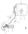
- the breast shield 1 has a breast cup funnel 10, which in use is applied to the breast of the mother.
- the funnel 10 merges into a breast cup neck 11, to which a first and a second breast cup coupling part 12, 13 adjoin.
- the first breast cup coupling part 12 has an internal thread, which can be screwed onto an external thread of the milk collection container 2, here a baby bottle.
- the second breast cup coupling part 13 has a connection part, not visible in the figure, into which the suction line 3, in this case a tube, can be inserted.
- the other end of the hose can be inserted in the suction pump 4.
- the vacuum generated in the suction pump or the negative pressure generated there is applied to the breast shield, so that the milk can be pumped out of the mother's breast and collected in the milk collection container 2.
- FIG. 1 is the usual position of use shown.
- the first coupling part 12 is directed downwards, the second coupling part 13 towards the rear or obliquely downwards, in any case away from the mother's breast.
- Saugpumpentician 4 can be used all known motor-driven devices.
- a suction pump of the applicant is used, which is known under the trade name Symphony.
- the suction pump unit has operation buttons and buttons 40 and a display 41. In the embodiment shown here, it is designed as a standalone portable device. However, it can also be attached to the breast cap, so that the suction line 3 is omitted. Such devices are also known in the market.
- a transmitting and / or optional receiving unit 5 is now present on the chest hood side, which in this example has an antenna 50 for transmitting and / or optionally receiving signals.
- the antenna 50 is shown here above the housing of the remaining unit. However, it can also be arranged in the housing and in particular be designed flat. Instead of a radio antenna, it is also possible to use other means for wireless communication, for example an infrared interface, Bluetooth, optical or acoustic signals, a passive resonance tuning element, RFID or other known means.
- the transmitting and receiving unit 5 has operating buttons 51, 52, 53, which are preferably arranged so that they are easily accessible and operable for the mother, without having to loosen their hand pressing the buttons of the breast shield.
- buttons 51, 52, 53 can also use knobs, inductive touch panels, slides, switches or other controls known type.
- the transmitting and receiving unit can be equipped with an optical and / or acoustic display.
- the display can be used, for example, to display status information, such as the pumping frequency and pumping capacity, the selected pumping program or whether it is currently being programmed. It can also be the various See options of the suction pump, such as the available pump curve curves, to make an appropriate choice.
- the display may have an acoustic signal generator, for example an alarm for noticing incorrect operation of individual elements of the set and / or a sounder for announcing a transmission or reception of signals.
- an acoustic signal generator for example an alarm for noticing incorrect operation of individual elements of the set and / or a sounder for announcing a transmission or reception of signals.
- the transmitting and receiving unit 5 is preferably arranged in the region of the breast tube funnel 10. In the example shown here, it is attached adjacent to the funnel 10 on the breast cup neck 11 and embedded in this. Preferably, in the position of use shown here, it is directed upwards so that it can be reached with the same hand with which the mother holds the breast shield 1 against her breast.
- the unit 5 can also be arranged, for example, laterally or at the bottom of the neck 11.
- the main body of the breast shield 1 is itself usually made of plastic and formed one or more pieces.
- the unit 5 may for example be cast into this body or glued to it.
- the base body may have a corresponding recess for plug-in reception of the unit 5, so that it does not protrude too much and is thus protected. Any cables for signal transmission can be connected in the same way with the breast cup 1 or enter into this.
- the unit 5 may be a pure signal transmitting unit without receiving function, or a combined signal transmitting and receiving unit.
- the suction pump unit preferably also has a signal transmission and / or signal reception unit. Again, the three combinations mentioned above are possible, and they should lead in combination with the unit 5 to a functioning uni- or bidirectional communication. That is, if one is a pure transmitter, the other can transmit the one transmitted by the first
- the suction pump unit 4 has an antenna or other suitable interface for wireless communication.
- FIG. 1 the communication is bidirectional.
- the chest-side signals are denoted by the reference numeral 8 and the suction pump-side signals are designated by the reference numeral 9.
- a signal transmission unit is arranged on the chest-hood side for transmitting signals to the suction pump unit, wherein the signal transmission unit comprises a programming device for manual or automatic programming of the suction pump unit.
- the programming device transmits a manual pumping operation to the suction pump unit. It may additionally or instead also transmit a stored pumping operation to the suction pump unit and activate it in the suction pump unit.
- Corresponding signals can be brought to display information in the area of the breast shield or can also be sent, for example, to data processing units for data evaluation.
- a signal receiver unit it can also be arranged in the region of the breast shield a signal receiver unit, wherein the suction pump unit and / or an external data processing device has a corresponding transmitter.
- the signal unit may have operating means for operating the suction pump, for example to turn the pump on and off to select the frequency, the pumping power or a special pumping program. It can be a manual Pumping mode or a pumping mode programmed by the operating means.
- the breast pump may be equipped with a signal transmitting unit for transmitting signals to the chestnut signal receiver unit.
- the breast pump may be equipped with a signal transmitting and signal receiving unit for transmitting and receiving signals to the chest-side signal receiver and transmitter unit or from the chest-side signal receiver and transmitter unit.
- the information transmitted may be, for example, one or more of the following group: suction frequency, suction power, pumping program used, pumping programs available for selection, pumping time, time, level in the milk collecting container, breast tube temperature, milk flow measurement.
- suction frequency suction power
- pumping program used pumping programs available for selection
- pumping time time
- time level in the milk collecting container
- breast tube temperature milk flow measurement.
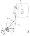
- FIG. 2 Now, a second embodiment is shown. The same parts are provided here and in the following examples with the same reference numerals and are therefore not repeated.
- the breast-hood-side transmitting and / or optional receiving unit 5 is no longer arranged on the breastshield 1 but on the suction line 3 in this example. In a further variant, it can also be arranged on a plug connection between breast cap 1 and suction line 3.
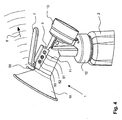
- FIG. 4 a variant of a breast shield 1 is shown, which can be used in all embodiments. It has an operating switch or lever 7, via which a manual pumping mode or rhythm (time course of the vacuum) can be specified by the mother, whose signals are sent to the suction pump unit 4 be transmitted.
- a manual pumping mode or rhythm time course of the vacuum
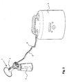
- the communication 8 ", 9" takes place between external device 4 'and suction pump unit 4.
- the communications may also take place simultaneously or sequentially between the external device and the breastplate, external device and suction pump unit and breastshield and suction pump unit.
- the transmitter and receiver unit 5 is not shown. It may, of course, be present or absent in the communication between the two devices mentioned above.
- the breast pump set according to the invention facilitates the operation of the pump and the breast shield during pumping off.
Claims (15)
- Ensemble tire-lait pour soutirer du lait maternel humain, l'ensemble tire-lait présentant au moins une téterelle (1) destinée à être appliquée sur un sein maternel et munie d'une partie d'accouplement (12) destinée à être reliée avec un récipient de collecte de lait (2) et une unité à pompe de succion (4) munie d'une pompe de succion à entraînement électrique, une première unité d'émission de signaux (5) étant disposée du côté de la téterelle pour la transmission de signaux à l'unité à pompe de succion (4) et cette première unité d'émission de signaux (5) comprenant un dispositif de programmation pour la programmation manuelle ou automatique de l'unité à pompe de succion (4), caractérisé en ce que le dispositif de programmation est configuré pour transmettre une opération de pompage mise en mémoire à l'unité à pompe de succion (4).
- Ensemble tire-lait selon la revendication 1, avec lequel le dispositif de programmation détecte une opération de pompage manuelle et transmet celle-ci à l'unité à pompe de succion (4) et/ou avec lequel le dispositif de programmation active une opération de pompage mise en mémoire dans l'unité à pompe de succion (4).
- Ensemble tire-lait selon la revendication 1 ou 2, avec lequel la première unité d'émission de signaux (5) est configurée pour la transmission sans fil des signaux.
- Ensemble tire-lait selon l'une des revendications 1 à 3, avec lequel l'ensemble tire-lait présente deux unités d'émission de signaux et avec lequel la première unité d'émission de signaux (5) est disposée du côté de la téterelle et une deuxième unité d'émission de signaux du côté de la pompe de succion.
- Ensemble tire-lait selon la revendication 4, avec lequel les deux unités d'émission de signaux sont configurées pour la transmission sans fil des signaux et/ou avec lequel l'unité d'émission de signaux (5) du côté de la téterelle est disposée de préférence sur la téterelle (1), sur un connecteur côté téterelle vers un tuyau de succion (3) entre la téterelle (1) et la pompe de succion (4) ou sur le tuyau de succion (3).
- Ensemble tire-lait selon l'une des revendications 1 à 5, avec lequel une unité de réception de signaux (5) est disposée dans la zone de la téterelle (1).
- Ensemble tire-lait selon la revendication 6, avec lequel l'unité de réception de signaux (5) est disposée sur ou dans la téterelle (1) et il existe pour chaque téterelle (1) une conduite de succion (3) pour relier la pompe de succion (4) avec l'au moins un tire-lait et avec lequel l'unité de réception de signaux (5) est disposée sur la conduite de succion (3) à côté de la téterelle (1) associée ou d'un connecteur entre la conduite de succion (3) et la téterelle (1).
- Ensemble tire-lait selon l'une des revendications 6 ou 7, avec lequel il existe dans la zone de la téterelle (1) un indicateur pour indiquer des informations, la circulation des informations s'effectuant de l'unité de réception de signaux (5) vers l'indicateur, l'indicateur étant de préférence un indicateur visuel et/ou sonore.
- Ensemble tire-lait selon l'une des revendications 6 à 8, avec lequel l'unité d'émission et de réception de signaux (5) présente de préférence des moyens de commande (51, 52, 53) pour commander la pompe de succion et/ou avec lequel le signal qui peut être transmis de l'unité d'émission et de réception de signaux (5) vers le tire-lait est de préférence un mode de pompage manuel ou un mode de pompage programmé par le biais du moyen de commande.
- Ensemble tire-lait selon l'une des revendications 6 à 9, avec lequel il existe entre l'unité de réception de signaux (5) et la pompe de succion une ligne électrique (6) analogique ou numérique pour la transmission des signaux ou avec lequel l'unité de réception de signaux (5) présente un récepteur et éventuellement un émetteur de ou pour un ou plusieurs signaux transmis sans fil.
- Ensemble tire-lait selon l'une des revendications 6 à 10, avec lequel le tire-lait est équipé d'une unité d'émission de signaux et éventuellement d'une unité de réception de signaux pour émettre et recevoir des signaux à l'unité d'émission et de réception de signaux (5) côté téterelle ou de la part de l'unité d'émission et de réception de signaux (5) côté téterelle.
- Ensemble tire-lait selon l'une des revendications 6 à 11, avec lequel il existe en plus de l'unité à pompe de succion (4) une unité externe (4'), laquelle est équipée d'une unité d'émission de signaux pour émettre des signaux à l'unité de réception de signaux (5) côté téterelle.
- Procédé pour faire fonctionner un système tire-lait selon l'une des revendications 6 à 12, selon lequel des signaux sont transmis à une unité de réception de signaux (5) côté téterelle, une ou plusieurs des informations suivantes étant de préférence transmises : fréquence de succion, puissance de succion, programme de pompage utilisé, programmes de pompage disponibles à la sélection, durée du pompage, heure, niveau de remplissage du récipient de collecte de lait, température de la téterelle, mesure du débit de lait.
- Procédé selon la revendication 13, selon lequel les signaux sont transmis depuis une unité à pompe de succion.
- Téterelle (1) destinée à être utilisée dans un ensemble tire-lait selon l'une des revendications 1 à 3, celle-ci présentant une unité d'émission de signaux (5) pour la transmission de signaux à une unité à pompe de succion (4), l'unité d'émission de signaux (5) comprenant un dispositif, de programmation pour la programmation manuelle ou automatique de l'unité à pompe de succion (4), et caractérisée en ce que le dispositif de programmation est configuré pour transmettre une opération de pompage mise en mémoire.
Priority Applications (1)
| Application Number | Priority Date | Filing Date | Title |
|---|---|---|---|
| PL07763937T PL2040774T3 (pl) | 2006-07-18 | 2007-07-10 | Zestaw do odciągania pokarmu |
Applications Claiming Priority (2)
| Application Number | Priority Date | Filing Date | Title |
|---|---|---|---|
| CH11562006 | 2006-07-18 | ||
| PCT/CH2007/000332 WO2008009145A1 (fr) | 2006-07-18 | 2007-07-10 | ensemble de pompe mammaire |
Publications (2)
| Publication Number | Publication Date |
|---|---|
| EP2040774A1 EP2040774A1 (fr) | 2009-04-01 |
| EP2040774B1 true EP2040774B1 (fr) | 2014-08-27 |
Family
ID=38564551
Family Applications (1)
| Application Number | Title | Priority Date | Filing Date |
|---|---|---|---|
| EP07763937.5A Active EP2040774B1 (fr) | 2006-07-18 | 2007-07-10 | Ensemble de pompe mammaire |
Country Status (8)
| Country | Link |
|---|---|
| US (1) | US8216179B2 (fr) |
| EP (1) | EP2040774B1 (fr) |
| JP (1) | JP5194007B2 (fr) |
| CN (1) | CN101489601B (fr) |
| CA (1) | CA2656116A1 (fr) |
| ES (1) | ES2523692T3 (fr) |
| PL (1) | PL2040774T3 (fr) |
| WO (1) | WO2008009145A1 (fr) |
Cited By (1)
| Publication number | Priority date | Publication date | Assignee | Title |
|---|---|---|---|---|
| US9844616B2 (en) | 2013-03-13 | 2017-12-19 | Medela Holding Ag | System and method for managing a supply of breast milk |
Families Citing this family (30)
| Publication number | Priority date | Publication date | Assignee | Title |
|---|---|---|---|---|
| US6749582B2 (en) | 2002-04-30 | 2004-06-15 | The First Years Inc. | Pumping breast milk |
| AU2009262881B2 (en) * | 2008-05-30 | 2013-05-23 | Solventum Intellectual Properties Company | Reduced-pressure, compression systems and apparatuses for use on a curved body part |
| US8398584B2 (en) | 2009-01-16 | 2013-03-19 | Learning Curve Brands, Inc. | Breast pump and method of use |
| EP2277571A1 (fr) * | 2009-07-23 | 2011-01-26 | Koninklijke Philips Electronics N.V. | Détection d'une réponse physiologique chez une utilisatrice d'une pompe à lait |
| JP2014530674A (ja) * | 2011-09-26 | 2014-11-20 | バサ アプライド テクノロシーズ リミテッド | 搾乳器による母乳分泌の流量及びパターンを制御するための装置と方法 |
| US9616156B2 (en) | 2013-03-24 | 2017-04-11 | Naya Health, Inc. | Method, apparatus, and system for expression and quantification of human breast milk |
| US10617805B2 (en) | 2014-03-20 | 2020-04-14 | Exploramed Nc7, Inc. | Fluid measuring reservoir for breast pumps |
| US10639406B2 (en) | 2014-03-20 | 2020-05-05 | Exploramed Nc7, Inc. | Methods and apparatus for transferring pressure during expression of human breast milk |
| CN106102455A (zh) * | 2014-02-07 | 2016-11-09 | 纳亚健康公司 | 用于吸取人类乳汁的方法、装置和系统 |
| EP2916249A1 (fr) * | 2014-03-06 | 2015-09-09 | Medela Holding AG | Système de service |
| CN107182202B (zh) * | 2014-07-22 | 2020-12-22 | 威洛创新股份有限公司 | 吸乳泵系统及方法 |
| WO2016044802A1 (fr) * | 2014-09-19 | 2016-03-24 | Naya Health, Inc. | Quantification et gestion de réserves de lait maternel humain tiré |
| CN105983146A (zh) * | 2015-03-06 | 2016-10-05 | 浙江辉伦婴童用品有限公司 | 利用手机移动终端控制的吸奶器 |
| EP3280468B1 (fr) | 2015-04-06 | 2019-11-06 | Medela Holding AG | Système d'extraction de lait maternel amélioré doté de caractéristiques de détection, de rétroaction et de connectabilité |
| ES2793350T3 (es) | 2015-04-08 | 2020-11-13 | Exploramed Nc7 Inc | Depósito de medición de fluidos para extractores de leche |
| CN106139277B (zh) * | 2015-04-23 | 2018-08-24 | 浙江辉伦婴童用品有限公司 | 根据音乐节奏进行工作的吸奶器 |
| CN106139279B (zh) * | 2015-04-23 | 2018-08-24 | 浙江辉伦婴童用品有限公司 | 利用移动终端控制奶量和吸奶频率的系统及其方法 |
| CN106139281B (zh) * | 2015-04-23 | 2018-09-28 | 浙江辉伦婴童用品有限公司 | 利用移动终端控制根据音乐节奏进行工作的吸奶器的系统及其控制方法 |
| US20170112983A1 (en) * | 2015-10-22 | 2017-04-27 | Regents Of The University Of Minnesota | Massaging lactation assistive device |
| TWI621452B (zh) * | 2016-11-25 | 2018-04-21 | Mamaway Licensing Co Ltd | Electric breast pump |
| US11147905B2 (en) | 2017-01-11 | 2021-10-19 | Momi Brands, Inc. | Breast pump |
| US10016548B1 (en) | 2017-01-11 | 2018-07-10 | Carr Lane Quackenbush | Breast pump |
| US11413381B2 (en) | 2017-01-11 | 2022-08-16 | Momtech Inc. | Breast pump |
| US11116880B2 (en) | 2019-10-29 | 2021-09-14 | Momi Brands, Inc. | Manual breast pump |
| CN108355181A (zh) * | 2018-02-08 | 2018-08-03 | 滨海昌正企业管理有限公司 | 电动吸奶器控制方法、装置及系统 |
| CN108355182B (zh) * | 2018-04-12 | 2020-11-17 | 马丽 | 吸奶器及吸奶器套装 |
| WO2020051438A1 (fr) | 2018-09-06 | 2020-03-12 | Lansinoh Laboratories, Inc. | Tire-lait électrique à boucle fermée |
| US11426499B2 (en) * | 2018-09-06 | 2022-08-30 | Lansinoh Laboratories, Inc. | Breast pumps |
| EP3628343A1 (fr) | 2018-09-27 | 2020-04-01 | Medela Holding AG | Tire-lait |
| EP3679958A1 (fr) * | 2019-01-09 | 2020-07-15 | Medela Holding AG | Pompe d'aspiration pourvue d'indicateur d'état optique |
Family Cites Families (21)
| Publication number | Priority date | Publication date | Assignee | Title |
|---|---|---|---|---|
| GB8422861D0 (en) * | 1984-09-11 | 1984-10-17 | Avent Medical Ltd | Single handed breast pump |
| US5542921A (en) * | 1994-11-04 | 1996-08-06 | Gerber Products Company | Electric breast pump |
| US5571084A (en) * | 1994-12-12 | 1996-11-05 | Spread Spectrum Inc. | Microprocessor-controlled vested lactation system |
| US8282596B2 (en) * | 1999-12-10 | 2012-10-09 | Medela Holding Ag | Breastpump with letdown feature |
| CH690956A5 (de) * | 1995-10-03 | 2001-03-15 | Trimed Ag | Regeleinrichtung, insbesondere für eine Muttermilchabsaugeinrichtung. |
| US6110140A (en) * | 1996-09-17 | 2000-08-29 | Medela, Inc. | Manual breastmilk pump |
| NO307079B1 (no) * | 1996-11-12 | 2000-02-07 | Tone Nordvik | Ammeanordning |
| US6109100A (en) * | 1997-09-03 | 2000-08-29 | Buckley; Scott F. | Pressure-or flow-sensitive feeding monitor |
| US6004288A (en) * | 1998-11-24 | 1999-12-21 | Hochstedler; Judy R. | Breast pump |
| WO2000041744A1 (fr) * | 1999-01-12 | 2000-07-20 | Elena Taggart Medo | Dispositif a base d'une pompe mammaire servant a faciliter un reflexe d'ejection de lait et procedes d'utilisation |
| US6673036B1 (en) * | 1999-10-13 | 2004-01-06 | The First Years Inc. | Pumping breast milk |
| US6676631B1 (en) * | 1999-12-10 | 2004-01-13 | Medela Holding Ag | Vacuum and rate control for a breastpump |
| US6706012B2 (en) * | 2000-06-12 | 2004-03-16 | L. Jason Clute | Apparatus for expressing milk |
| US6866994B2 (en) * | 2001-05-30 | 2005-03-15 | Neomatrix, Llc | Noninvasive intraductal fluid diagnostic screen |
| US7789865B2 (en) * | 2002-06-19 | 2010-09-07 | Myers Kenneth E | Breast cup with an internal vacuum chamber for a hands-free breast pump |
| WO2002102437A2 (fr) * | 2001-06-19 | 2002-12-27 | Whisper Wear, Inc. | Systeme destine a un tire-lait mains libres, portatif, et procede d'utilisation associe |
| WO2003066132A1 (fr) * | 2002-02-07 | 2003-08-14 | Medela Ag | Embout tire-lait |
| GB2404590B (en) * | 2003-08-01 | 2005-06-01 | Cannon Rubber Ltd | Powered breast pump |
| US8137305B2 (en) * | 2007-01-22 | 2012-03-20 | Kelly Patricia A | Programmable electric breast pump |
| JP3102400U (ja) * | 2003-12-19 | 2004-07-02 | 睦翔 林 | 搾乳器用分離式補助装置 |
| CN101111274B (zh) * | 2005-01-28 | 2011-03-02 | 美德乐控股公司 | 吸奶器组件 |
-
2007
- 2007-07-10 EP EP07763937.5A patent/EP2040774B1/fr active Active
- 2007-07-10 JP JP2009519773A patent/JP5194007B2/ja active Active
- 2007-07-10 ES ES07763937.5T patent/ES2523692T3/es active Active
- 2007-07-10 PL PL07763937T patent/PL2040774T3/pl unknown
- 2007-07-10 US US12/374,038 patent/US8216179B2/en active Active
- 2007-07-10 WO PCT/CH2007/000332 patent/WO2008009145A1/fr active Application Filing
- 2007-07-10 CA CA002656116A patent/CA2656116A1/fr not_active Abandoned
- 2007-07-10 CN CN2007800271459A patent/CN101489601B/zh active Active
Cited By (1)
| Publication number | Priority date | Publication date | Assignee | Title |
|---|---|---|---|---|
| US9844616B2 (en) | 2013-03-13 | 2017-12-19 | Medela Holding Ag | System and method for managing a supply of breast milk |
Also Published As
| Publication number | Publication date |
|---|---|
| JP5194007B2 (ja) | 2013-05-08 |
| US8216179B2 (en) | 2012-07-10 |
| JP2009543618A (ja) | 2009-12-10 |
| US20100016789A1 (en) | 2010-01-21 |
| ES2523692T3 (es) | 2014-11-28 |
| EP2040774A1 (fr) | 2009-04-01 |
| CA2656116A1 (fr) | 2008-01-24 |
| PL2040774T3 (pl) | 2015-03-31 |
| WO2008009145A1 (fr) | 2008-01-24 |
| CN101489601A (zh) | 2009-07-22 |
| CN101489601B (zh) | 2011-11-23 |
Similar Documents
| Publication | Publication Date | Title |
|---|---|---|
| EP2040774B1 (fr) | Ensemble de pompe mammaire | |
| EP1843807B1 (fr) | Ensemble tire-lait | |
| DE10148049B4 (de) | Automatische Spritzenvorrichtung | |
| DE60106141T2 (de) | Gerät zur informationsbeobachtung auf abstand für medizinische vorrichtung | |
| EP1890743B1 (fr) | Transmission de donnees a energie optimisee pour un appareil medical | |
| EP1882484B1 (fr) | Agencement de transmission | |
| EP0002776B1 (fr) | Dispositif pour l'infusion préprogrammée d'insuline | |
| EP0742308B1 (fr) | Appareil domestique avec dispositif d'affichage | |
| DE60029784T2 (de) | Kostengüstige infusionsvorrichtung | |
| DE60115707T2 (de) | Medizinisches gerät zur fernbedienung | |
| EP1574164A1 (fr) | Système de surveillance de patient | |
| DE10020690A1 (de) | Telemetrie-System für implantierbare medizinische Geräte | |
| EP1155707A1 (fr) | Pompe à perfusion | |
| DE19927853A1 (de) | In ein medizinisches Managementsystem integrierte Programmiervorrichtung zur Kommunikation mit einer implantierbaren medizinischen Vorrichtung | |
| DE19930256A1 (de) | Implantat mit Nah- und Fernfeldtelemetrie | |
| DE10053116A1 (de) | Apparat und Verfahren zur automatischen Softwareaktualisierung aus der Ferne von medizinischen Vorrichtungssystemen | |
| DE10055171A1 (de) | Fernzustellung einer auf Software basierenden Ausbildung über einpflanzbare medizinische Vorrichtungssysteme | |
| DE102007051756A1 (de) | Vorrichtung zur Bestimmung eines Nachsorgetermins für die Versorgung eines implantierbaren medizinischen Gerätes | |
| DE102010034192A1 (de) | EKG-Handgerät | |
| DE102005005882A1 (de) | Verfahren zum schnurlosen Steuern einer Nähmaschine | |
| EP1519623B1 (fr) | Télécommande pour des prothèses auditives | |
| EP3269423A1 (fr) | Appareil medical implantable comprenant une antenne pour la communication sans fil | |
| DE602004010245T2 (de) | Drahtlose Kommunikation physiologischer Variablen | |
| DE10009591B4 (de) | Messvorrichtung zur Überwachung von Körperfunktionsparametern | |
| WO2019052607A2 (fr) | Thermomètre numérique, notamment thermomètre numérique rectal ou auriculaire, systèmes et procédé assisté par ordinateur de contrôle de la température corporelle |
Legal Events
| Date | Code | Title | Description |
|---|---|---|---|
| PUAI | Public reference made under article 153(3) epc to a published international application that has entered the european phase |
Free format text: ORIGINAL CODE: 0009012 |
|
| 17P | Request for examination filed |
Effective date: 20090206 |
|
| AK | Designated contracting states |
Kind code of ref document: A1 Designated state(s): AT BE BG CH CY CZ DE DK EE ES FI FR GB GR HU IE IS IT LI LT LU LV MC MT NL PL PT RO SE SI SK TR |
|
| AX | Request for extension of the european patent |
Extension state: AL BA HR MK RS |
|
| 17Q | First examination report despatched |
Effective date: 20091105 |
|
| DAX | Request for extension of the european patent (deleted) | ||
| GRAP | Despatch of communication of intention to grant a patent |
Free format text: ORIGINAL CODE: EPIDOSNIGR1 |
|
| INTG | Intention to grant announced |
Effective date: 20140304 |
|
| GRAS | Grant fee paid |
Free format text: ORIGINAL CODE: EPIDOSNIGR3 |
|
| GRAA | (expected) grant |
Free format text: ORIGINAL CODE: 0009210 |
|
| AK | Designated contracting states |
Kind code of ref document: B1 Designated state(s): AT BE BG CH CY CZ DE DK EE ES FI FR GB GR HU IE IS IT LI LT LU LV MC MT NL PL PT RO SE SI SK TR |
|
| REG | Reference to a national code |
Ref country code: GB Ref legal event code: FG4D Free format text: NOT ENGLISH |
|
| REG | Reference to a national code |
Ref country code: CH Ref legal event code: EP |
|
| REG | Reference to a national code |
Ref country code: AT Ref legal event code: REF Ref document number: 684201 Country of ref document: AT Kind code of ref document: T Effective date: 20140915 |
|
| REG | Reference to a national code |
Ref country code: IE Ref legal event code: FG4D Free format text: LANGUAGE OF EP DOCUMENT: GERMAN |
|
| REG | Reference to a national code |
Ref country code: DE Ref legal event code: R096 Ref document number: 502007013401 Country of ref document: DE Effective date: 20141009 |
|
| REG | Reference to a national code |
Ref country code: CH Ref legal event code: NV Representative=s name: ISLER AND PEDRAZZINI AG, CH |
|
| REG | Reference to a national code |
Ref country code: ES Ref legal event code: FG2A Ref document number: 2523692 Country of ref document: ES Kind code of ref document: T3 Effective date: 20141128 |
|
| REG | Reference to a national code |
Ref country code: SE Ref legal event code: TRGR |
|
| REG | Reference to a national code |
Ref country code: NL Ref legal event code: T3 |
|
| REG | Reference to a national code |
Ref country code: LT Ref legal event code: MG4D |
|
| PG25 | Lapsed in a contracting state [announced via postgrant information from national office to epo] |
Ref country code: BG Free format text: LAPSE BECAUSE OF FAILURE TO SUBMIT A TRANSLATION OF THE DESCRIPTION OR TO PAY THE FEE WITHIN THE PRESCRIBED TIME-LIMIT Effective date: 20141127 Ref country code: LT Free format text: LAPSE BECAUSE OF FAILURE TO SUBMIT A TRANSLATION OF THE DESCRIPTION OR TO PAY THE FEE WITHIN THE PRESCRIBED TIME-LIMIT Effective date: 20140827 Ref country code: GR Free format text: LAPSE BECAUSE OF FAILURE TO SUBMIT A TRANSLATION OF THE DESCRIPTION OR TO PAY THE FEE WITHIN THE PRESCRIBED TIME-LIMIT Effective date: 20141128 Ref country code: FI Free format text: LAPSE BECAUSE OF FAILURE TO SUBMIT A TRANSLATION OF THE DESCRIPTION OR TO PAY THE FEE WITHIN THE PRESCRIBED TIME-LIMIT Effective date: 20140827 Ref country code: PT Free format text: LAPSE BECAUSE OF FAILURE TO SUBMIT A TRANSLATION OF THE DESCRIPTION OR TO PAY THE FEE WITHIN THE PRESCRIBED TIME-LIMIT Effective date: 20141229 |
|
| PG25 | Lapsed in a contracting state [announced via postgrant information from national office to epo] |
Ref country code: IS Free format text: LAPSE BECAUSE OF FAILURE TO SUBMIT A TRANSLATION OF THE DESCRIPTION OR TO PAY THE FEE WITHIN THE PRESCRIBED TIME-LIMIT Effective date: 20141227 Ref country code: CY Free format text: LAPSE BECAUSE OF FAILURE TO SUBMIT A TRANSLATION OF THE DESCRIPTION OR TO PAY THE FEE WITHIN THE PRESCRIBED TIME-LIMIT Effective date: 20140827 Ref country code: LV Free format text: LAPSE BECAUSE OF FAILURE TO SUBMIT A TRANSLATION OF THE DESCRIPTION OR TO PAY THE FEE WITHIN THE PRESCRIBED TIME-LIMIT Effective date: 20140827 |
|
| REG | Reference to a national code |
Ref country code: PL Ref legal event code: T3 |
|
| PG25 | Lapsed in a contracting state [announced via postgrant information from national office to epo] |
Ref country code: CZ Free format text: LAPSE BECAUSE OF FAILURE TO SUBMIT A TRANSLATION OF THE DESCRIPTION OR TO PAY THE FEE WITHIN THE PRESCRIBED TIME-LIMIT Effective date: 20140827 Ref country code: RO Free format text: LAPSE BECAUSE OF FAILURE TO SUBMIT A TRANSLATION OF THE DESCRIPTION OR TO PAY THE FEE WITHIN THE PRESCRIBED TIME-LIMIT Effective date: 20140827 Ref country code: DK Free format text: LAPSE BECAUSE OF FAILURE TO SUBMIT A TRANSLATION OF THE DESCRIPTION OR TO PAY THE FEE WITHIN THE PRESCRIBED TIME-LIMIT Effective date: 20140827 Ref country code: EE Free format text: LAPSE BECAUSE OF FAILURE TO SUBMIT A TRANSLATION OF THE DESCRIPTION OR TO PAY THE FEE WITHIN THE PRESCRIBED TIME-LIMIT Effective date: 20140827 Ref country code: SK Free format text: LAPSE BECAUSE OF FAILURE TO SUBMIT A TRANSLATION OF THE DESCRIPTION OR TO PAY THE FEE WITHIN THE PRESCRIBED TIME-LIMIT Effective date: 20140827 |
|
| REG | Reference to a national code |
Ref country code: DE Ref legal event code: R097 Ref document number: 502007013401 Country of ref document: DE |
|
| REG | Reference to a national code |
Ref country code: FR Ref legal event code: PLFP Year of fee payment: 9 |
|
| PLBE | No opposition filed within time limit |
Free format text: ORIGINAL CODE: 0009261 |
|
| STAA | Information on the status of an ep patent application or granted ep patent |
Free format text: STATUS: NO OPPOSITION FILED WITHIN TIME LIMIT |
|
| 26N | No opposition filed |
Effective date: 20150528 |
|
| PG25 | Lapsed in a contracting state [announced via postgrant information from national office to epo] |
Ref country code: SI Free format text: LAPSE BECAUSE OF FAILURE TO SUBMIT A TRANSLATION OF THE DESCRIPTION OR TO PAY THE FEE WITHIN THE PRESCRIBED TIME-LIMIT Effective date: 20140827 |
|
| PG25 | Lapsed in a contracting state [announced via postgrant information from national office to epo] |
Ref country code: MC Free format text: LAPSE BECAUSE OF FAILURE TO SUBMIT A TRANSLATION OF THE DESCRIPTION OR TO PAY THE FEE WITHIN THE PRESCRIBED TIME-LIMIT Effective date: 20140827 |
|
| PG25 | Lapsed in a contracting state [announced via postgrant information from national office to epo] |
Ref country code: LU Free format text: LAPSE BECAUSE OF FAILURE TO SUBMIT A TRANSLATION OF THE DESCRIPTION OR TO PAY THE FEE WITHIN THE PRESCRIBED TIME-LIMIT Effective date: 20150710 |
|
| REG | Reference to a national code |
Ref country code: IE Ref legal event code: MM4A |
|
| REG | Reference to a national code |
Ref country code: FR Ref legal event code: PLFP Year of fee payment: 10 |
|
| PG25 | Lapsed in a contracting state [announced via postgrant information from national office to epo] |
Ref country code: IE Free format text: LAPSE BECAUSE OF NON-PAYMENT OF DUE FEES Effective date: 20150710 |
|
| REG | Reference to a national code |
Ref country code: AT Ref legal event code: MM01 Ref document number: 684201 Country of ref document: AT Kind code of ref document: T Effective date: 20150710 |
|
| PG25 | Lapsed in a contracting state [announced via postgrant information from national office to epo] |
Ref country code: AT Free format text: LAPSE BECAUSE OF NON-PAYMENT OF DUE FEES Effective date: 20150710 |
|
| PG25 | Lapsed in a contracting state [announced via postgrant information from national office to epo] |
Ref country code: MT Free format text: LAPSE BECAUSE OF FAILURE TO SUBMIT A TRANSLATION OF THE DESCRIPTION OR TO PAY THE FEE WITHIN THE PRESCRIBED TIME-LIMIT Effective date: 20140827 |
|
| PG25 | Lapsed in a contracting state [announced via postgrant information from national office to epo] |
Ref country code: HU Free format text: LAPSE BECAUSE OF FAILURE TO SUBMIT A TRANSLATION OF THE DESCRIPTION OR TO PAY THE FEE WITHIN THE PRESCRIBED TIME-LIMIT; INVALID AB INITIO Effective date: 20070710 |
|
| REG | Reference to a national code |
Ref country code: FR Ref legal event code: PLFP Year of fee payment: 11 |
|
| REG | Reference to a national code |
Ref country code: FR Ref legal event code: PLFP Year of fee payment: 12 |
|
| PGFP | Annual fee paid to national office [announced via postgrant information from national office to epo] |
Ref country code: PL Payment date: 20220622 Year of fee payment: 16 |
|
| PGFP | Annual fee paid to national office [announced via postgrant information from national office to epo] |
Ref country code: TR Payment date: 20220707 Year of fee payment: 16 Ref country code: SE Payment date: 20220720 Year of fee payment: 16 |
|
| P01 | Opt-out of the competence of the unified patent court (upc) registered |
Effective date: 20230524 |
|
| PGFP | Annual fee paid to national office [announced via postgrant information from national office to epo] |
Ref country code: NL Payment date: 20230719 Year of fee payment: 17 |
|
| PGFP | Annual fee paid to national office [announced via postgrant information from national office to epo] |
Ref country code: IT Payment date: 20230719 Year of fee payment: 17 Ref country code: GB Payment date: 20230720 Year of fee payment: 17 Ref country code: ES Payment date: 20230926 Year of fee payment: 17 Ref country code: CH Payment date: 20230801 Year of fee payment: 17 |
|
| PGFP | Annual fee paid to national office [announced via postgrant information from national office to epo] |
Ref country code: FR Payment date: 20230725 Year of fee payment: 17 Ref country code: DE Payment date: 20230719 Year of fee payment: 17 Ref country code: BE Payment date: 20230719 Year of fee payment: 17 |
|
| REG | Reference to a national code |
Ref country code: SE Ref legal event code: EUG |