EP2040123B9 - Projection optical system - Google Patents
Projection optical system Download PDFInfo
- Publication number
- EP2040123B9 EP2040123B9 EP09000246A EP09000246A EP2040123B9 EP 2040123 B9 EP2040123 B9 EP 2040123B9 EP 09000246 A EP09000246 A EP 09000246A EP 09000246 A EP09000246 A EP 09000246A EP 2040123 B9 EP2040123 B9 EP 2040123B9
- Authority
- EP
- European Patent Office
- Prior art keywords
- lenses
- optical system
- projection optical
- group
- lens
- Prior art date
- Legal status (The legal status is an assumption and is not a legal conclusion. Google has not performed a legal analysis and makes no representation as to the accuracy of the status listed.)
- Expired - Fee Related
Links
- 230000003287 optical effect Effects 0.000 title claims description 233
- 238000003384 imaging method Methods 0.000 claims description 55
- 239000000758 substrate Substances 0.000 claims description 19
- 238000004519 manufacturing process Methods 0.000 claims description 13
- 230000005855 radiation Effects 0.000 claims description 11
- 238000005286 illumination Methods 0.000 claims description 9
- 238000000059 patterning Methods 0.000 claims description 8
- 230000008859 change Effects 0.000 claims description 6
- VYPSYNLAJGMNEJ-UHFFFAOYSA-N Silicium dioxide Chemical compound O=[Si]=O VYPSYNLAJGMNEJ-UHFFFAOYSA-N 0.000 description 60
- 239000000377 silicon dioxide Substances 0.000 description 53
- 229910052681 coesite Inorganic materials 0.000 description 50
- 229910052906 cristobalite Inorganic materials 0.000 description 50
- 229910052682 stishovite Inorganic materials 0.000 description 50
- 229910052905 tridymite Inorganic materials 0.000 description 50
- 239000000463 material Substances 0.000 description 45
- 238000013461 design Methods 0.000 description 17
- KRHYYFGTRYWZRS-UHFFFAOYSA-M Fluoride anion Chemical compound [F-] KRHYYFGTRYWZRS-UHFFFAOYSA-M 0.000 description 14
- 230000005499 meniscus Effects 0.000 description 12
- 230000004075 alteration Effects 0.000 description 11
- WUKWITHWXAAZEY-UHFFFAOYSA-L calcium difluoride Chemical compound [F-].[F-].[Ca+2] WUKWITHWXAAZEY-UHFFFAOYSA-L 0.000 description 11
- 229910001634 calcium fluoride Inorganic materials 0.000 description 10
- 238000000034 method Methods 0.000 description 8
- 238000012937 correction Methods 0.000 description 5
- 230000000875 corresponding effect Effects 0.000 description 5
- 239000013078 crystal Substances 0.000 description 5
- 239000002178 crystalline material Substances 0.000 description 4
- 238000010586 diagram Methods 0.000 description 4
- 239000005350 fused silica glass Substances 0.000 description 4
- 230000001965 increasing effect Effects 0.000 description 4
- NCGICGYLBXGBGN-UHFFFAOYSA-N 3-morpholin-4-yl-1-oxa-3-azonia-2-azanidacyclopent-3-en-5-imine;hydrochloride Chemical compound Cl.[N-]1OC(=N)C=[N+]1N1CCOCC1 NCGICGYLBXGBGN-UHFFFAOYSA-N 0.000 description 3
- 210000001015 abdomen Anatomy 0.000 description 2
- 230000003247 decreasing effect Effects 0.000 description 2
- 238000000280 densification Methods 0.000 description 2
- 230000000694 effects Effects 0.000 description 2
- 239000011521 glass Substances 0.000 description 2
- 238000005259 measurement Methods 0.000 description 2
- 238000012360 testing method Methods 0.000 description 2
- 238000012546 transfer Methods 0.000 description 2
- 206010010071 Coma Diseases 0.000 description 1
- 238000013459 approach Methods 0.000 description 1
- OYLGJCQECKOTOL-UHFFFAOYSA-L barium fluoride Chemical compound [F-].[F-].[Ba+2] OYLGJCQECKOTOL-UHFFFAOYSA-L 0.000 description 1
- 229910001632 barium fluoride Inorganic materials 0.000 description 1
- 230000005540 biological transmission Effects 0.000 description 1
- 238000005056 compaction Methods 0.000 description 1
- 230000002596 correlated effect Effects 0.000 description 1
- 230000001419 dependent effect Effects 0.000 description 1
- 230000001627 detrimental effect Effects 0.000 description 1
- 238000010894 electron beam technology Methods 0.000 description 1
- 230000002708 enhancing effect Effects 0.000 description 1
- 150000002222 fluorine compounds Chemical class 0.000 description 1
- 239000010436 fluorite Substances 0.000 description 1
- 239000004973 liquid crystal related substance Substances 0.000 description 1
- 238000012986 modification Methods 0.000 description 1
- 230000004048 modification Effects 0.000 description 1
- 238000000206 photolithography Methods 0.000 description 1
- 230000000704 physical effect Effects 0.000 description 1
- 230000008569 process Effects 0.000 description 1
- 230000001902 propagating effect Effects 0.000 description 1
- 230000009467 reduction Effects 0.000 description 1
- 239000004065 semiconductor Substances 0.000 description 1
- 239000000126 substance Substances 0.000 description 1
Images

Classifications
-
- G—PHYSICS
- G02—OPTICS
- G02B—OPTICAL ELEMENTS, SYSTEMS OR APPARATUS
- G02B9/00—Optical objectives characterised both by the number of the components and their arrangements according to their sign, i.e. + or -
- G02B9/34—Optical objectives characterised both by the number of the components and their arrangements according to their sign, i.e. + or - having four components only
-
- G—PHYSICS
- G03—PHOTOGRAPHY; CINEMATOGRAPHY; ANALOGOUS TECHNIQUES USING WAVES OTHER THAN OPTICAL WAVES; ELECTROGRAPHY; HOLOGRAPHY
- G03F—PHOTOMECHANICAL PRODUCTION OF TEXTURED OR PATTERNED SURFACES, e.g. FOR PRINTING, FOR PROCESSING OF SEMICONDUCTOR DEVICES; MATERIALS THEREFOR; ORIGINALS THEREFOR; APPARATUS SPECIALLY ADAPTED THEREFOR
- G03F7/00—Photomechanical, e.g. photolithographic, production of textured or patterned surfaces, e.g. printing surfaces; Materials therefor, e.g. comprising photoresists; Apparatus specially adapted therefor
- G03F7/70—Microphotolithographic exposure; Apparatus therefor
- G03F7/70216—Mask projection systems
- G03F7/70241—Optical aspects of refractive lens systems, i.e. comprising only refractive elements
-
- G—PHYSICS
- G02—OPTICS
- G02B—OPTICAL ELEMENTS, SYSTEMS OR APPARATUS
- G02B13/00—Optical objectives specially designed for the purposes specified below
- G02B13/14—Optical objectives specially designed for the purposes specified below for use with infrared or ultraviolet radiation
-
- G—PHYSICS
- G02—OPTICS
- G02B—OPTICAL ELEMENTS, SYSTEMS OR APPARATUS
- G02B13/00—Optical objectives specially designed for the purposes specified below
- G02B13/14—Optical objectives specially designed for the purposes specified below for use with infrared or ultraviolet radiation
- G02B13/143—Optical objectives specially designed for the purposes specified below for use with infrared or ultraviolet radiation for use with ultraviolet radiation
-
- G—PHYSICS
- G03—PHOTOGRAPHY; CINEMATOGRAPHY; ANALOGOUS TECHNIQUES USING WAVES OTHER THAN OPTICAL WAVES; ELECTROGRAPHY; HOLOGRAPHY
- G03F—PHOTOMECHANICAL PRODUCTION OF TEXTURED OR PATTERNED SURFACES, e.g. FOR PRINTING, FOR PROCESSING OF SEMICONDUCTOR DEVICES; MATERIALS THEREFOR; ORIGINALS THEREFOR; APPARATUS SPECIALLY ADAPTED THEREFOR
- G03F7/00—Photomechanical, e.g. photolithographic, production of textured or patterned surfaces, e.g. printing surfaces; Materials therefor, e.g. comprising photoresists; Apparatus specially adapted therefor
- G03F7/20—Exposure; Apparatus therefor
Definitions
- the present invention relates to a projection optical system, in particular a projection optical system having a high numerical aperture.
- Lithographic processes are commonly used in the manufacture of semiconductor elements, such as integrated circuits (ICs), LSIs, liquid crystal elements, micropatterened members and micromechanical components.
- ICs integrated circuits
- LSIs liquid crystal elements
- micropatterened members micromechanical components
- a projection exposure apparatus used for photolithography generally comprises an illumination optical system with a light source and a projection optical system.
- Light from the illumination optical system illuminates a reticle (a first object) having a given pattern and the projection optical system transfers an image of the reticle pattern (the first object), onto a region of a photo-sensitive substrate (a second object).
- the image of the reticle pattern may also be reduced in size by the projection optical system so as to produce a smaller image of the reticle pattern on the substrate.
- illumination light of wavelengths shorter than 200 nm is predominantly used in the recently developed projection exposure systems.
- High quality lens materials suitable for use in projection optical system having a high numerical aperture and at a short wavelength tend to be in short supply and are generally associated with high cost.
- projection optical systems with numerical apertures (on a substrate side of the projection optical system) up to 0.9 are known. Due to the need of correcting aberrations in the projection optical system, low angles of incidence and deflection of imaging beams (transferring an image of the first object onto the region of the second object) are generally preferred in such systems. This generally leads to projection optical systems comprising lenses of large diameter and a long distance between the first and the second object, or reticle and substrate, respectively. The large lens diameters and the long distance are, however, generally synonymous with a high mass of the lens material and thus high cost. As a consequence, the projection optical system tends to become rather heavy.
- EP-A-1 139 138 discloses a projection optical system for wave lengths shorter than 250 nm having plural aspherical lens surfaces.
- a sum of the absolute values of the total refractive powers of the first, second, third and fourth groups is a maximum value (a maximum value in particular in comparison to values obtainable by other possible divisions into groups).
- Lens as used herein, relates to a single lens element, not a optical system comprised of a plurality of lens elements.
- the projection optical system is preferably a purely refractive or dioptric projection optical system, i.e. does not comprise reflective optical elements such as mirrors.
- the arrangement of a negative lens group followed by a positive lens group, followed by a negative lens group, followed by a positive lens group in the direction of the optical axis (the given order starting at the first object) of the projection optical system according to the present invention results in what is generally referred to as a "single waist type" projection optical system.
- the waist indicates a constriction or a minimum diameter of the projection optical system.
- the waist is formed by lenses of the third group of lenses.
- V 1 is greater than 0.055.
- lenses having comparatively high refractive powers are used and thus an imaging beam used to transfer an image of the first object into a region of the second object may be subject to rather large angles of deflection/incidence.
- the use of lenses having relatively high refractive powers enables a compact design of the projection optical system, in particular a relatively short distance between the first and the second object as well as use of lenses with a comparatively small diameter. For instance, distances between the first object and the second object as short as about 1000 mm can be realized.
- a largest diameter of a lens in the projection optical system according to the present invention may be smaller than about 300 mm.
- E 2 ⁇ y ⁇ NA
- equation (1) can also be written as: E ⁇ ⁇ m ⁇ V 1
- the inventors of the present inventions found that advantageous, compact designs of projection optical systems with good imaging properties can be realised when a product of ⁇ m and E is greater than 0.045, in particular greater than 0.055, as already mentioned above.
- V 2 is greater than 5.
- this relation can be described as: sin ⁇ m ⁇ E > V 2 wherein ⁇ m is a mean value of the absolute values of the maximum deflection angles of the imaging beams at the surfaces of the lenses of the projection optical system, as defined by 1 k ⁇ ⁇ ⁇ i ⁇ 1 + ⁇ i ⁇ 2 in equation (5).
- a projection optical system having good imaging properties with deliberate use of at least one of high incidence angles and high deflection angles is quite in contrast to a general teaching that in an optical system, the smaller an angle is at which a light beam is incident onto each lens surface, the less aberrations are generated and the looser a tolerance becomes.
- Imaging errors are defined herein as any deviation of an imaging characteristic from an optimum value of the imaging characteristic.
- each of at least five lenses of the plurality of lenses has at least one aspherical surface.
- the projection exposure system does not contain more than 10 aspherical surfaces.
- the term "aspherical surface” is to be understood as referring to aspherical surfaces in which a maximum axial distance between the aspherical surface and a best fitting sphere is 2 ⁇ m or more. This definition serves to exclude spherical surfaces with unintended deformations as well as aspherical surface parts typically introduced after the manufacture of the lens/projection optical system for correction of aberrations which are generally due to the manufacturing process rather than inherent to the particular design of the projection optical system.
- an (imaginary) ideal spherical shape or best fitting sphere is chosen such that a centre and a periphery of the aspherical surface are positioned on the best fitting sphere and then an axial distance between the best fitting sphere and the aspherical surface determined.
- a radial surface profile and a best fitting sphere chosen in accordance with the above is illustrated in Figure 1a .
- an axial distance between the aspherical surface and a best fitting sphere is more than about 300 ⁇ m and less than about 500 ⁇ m.
- the best fitting sphere is chosen such that a centre and a periphery of the aspherical surface are positioned on the best fitting sphere.
- the above values indicate that the lens surfaces used are comparatively strongly aspherical, i.e. that a departure from a best fitting sphere is comparatively large.
- Such aspherical surfaces are preferably positioned in the first group of lenses and/or, if an aperture stop is provided in the projection optical system, close to the aperture stop.
- aspherical lenses in the projection optical system helps to reduce the length of the projection optical system and the required amount of lens material as well as to improve an imaging performance.
- an absolute value of a maximum change of curvature of the aspherical surface(s) (dc/ds) is greater than 300 m -2 .
- each of the at least five aspherical surfaces having effective diameters D as has a centre of curvature of the best fitting sphere disposed on a side of the aspherical surface facing away from the lens carrying the aspherical surface, wherein D as is 0.2 times a design-distance L D between the first object and the second object.
- an aspherical surface is preferably disposed on an surface of a lens which surface has an overall concave shape.
- CGHs Computer-generated holograms
- diffractive systems i.e. diffractive systems
- CGHs Computer-generated holograms
- computer-generated holograms are subject to practical limits in terms of manufacturability, in particular with respect to their size, due to the limitations imposed by the techniques used in the manufacture of CGHs, such as electron beam, laser beam and photolithographic techniques.
- this problem can be overcome or at least alleviated by placing aspherical surfaces in the projection optical system such that the aspherical surfaces are located on overall concave surfaces of the lenses, as described above.
- An overall concave surface of a lens is a surface which has a centre of curvature of the best fitting sphere disposed on a side of the aspherical surface facing away from the lens carrying the aspherical surface, as defined above.
- all aspherical surfaces which are part of lenses having a maximum diameter larger than about 200 mm are located on overall concave surfaces.
- the aspherical surfaces placed in accordance with the above have best fitting spheres associated with them which best fitting spheres have a radius greater than 300mm and/or smaller than 2000 mm.
- the lower limit is determined by factors relating to manufacturing and the upper limit determined by a largest feasible length of a "null optics" used in interferometric measuring the aspherical surface.
- Projection optical systems having aspherical and spherical surfaces at which angles of deflection/incidence are rather large allow to use relatively small amounts of glass, in particular in terms of a mass of glass, and thus help to decrease cost and weight of the projection optical system.
- V 4 is smaller than 35.
- G D is a suitable indicator of the amount, in particular in terms of mass, of lens material used in the projection optical system and thus cost associated with the lens material.
- the projection optical system comprises an aperture stop disposed between two lenses of the fourth group of lenses.
- the fourth group of lenses consists of a first sub-group of lenses in between the first object (or: the third group of lenses, more precisely) and the aperture stop and a second sub-group of lenses in between the aperture stop and the second object.
- the mismatch of the focal length of the lens unit comprising all lenses in between the aperture stop and the first object, and focal length of the second sub-group of the fourth group of lenses which comprises all lenses in between the aperture stop and the second object, serves to create an afocal projection optical system.
- design distance or “design length” as used herein stands for a distance between the first object and the second object in an operating or exposure mode, i.e. as foreseen by the design of the projection optical system when both the first and the second objects are in focus.
- a radial surface profile of an aspherical surface has at most one point of inflection of curvature.
- a radial surface profile of at most one aspherical surface has a point of inflection of curvature in an optically effective area of the aspherical surface. Since an aspherical surface is generally rotationally symmetrical, one point of inflection, as used herein, would encompass embodiments wherein the point of inflection extends in a given shape, in particular a circle, across the surface of the aspherical surface.
- the radial surface profile shown in Figure 1a for instance, would fall within the meaning of an aspherical surface having just one point of inflection.
- a focal length of the projection optical system is shorter than 250 mm.
- the choice of this particular focal length enables the realisation of good telecentric properties of the projection optical system, in particular on a side of the second object.
- At least one lens in the second sub-group of the fourth group of lenses is a lens of positive refractive power and the at least one lens fulfils the following conditions: i 1 ⁇ u 1 ⁇ i + u lo + i 2 ⁇ u 2 ⁇ i + u 2 ⁇ o > 2.5 and f 4 ⁇ p ⁇ 2500 mm wherein
- the first group of lenses is comprised only of lenses having negative refractive power, wherein one of the lenses of the first group is a meniscus lens having a convex surface facing the first object.
- the second group of lenses is comprised only of lenses having positive refractive power, wherein at least one of the lenses of the second group has a (overall) concave, aspherical surface.
- the second group of lenses comprises at least three lenses.
- At least one lens of the third group of lenses has an aspherical surface.
- the third group of lenses is comprised only of lenses having negative refractive power.
- the third group of lenses comprises three or more lenses of negative refractive power.
- a lens having positive refractive power is disposed between two lenses having negative refractive power in the third group of lenses.
- Embodiments of the projection optical system have proven to be advantageous when the first sub-group of the fourth group of lenses comprises at least one lens of negative refractive power, which lens has a first and a second surface and fulfils the following condition: c 11 + c 12 c 11 - c 12 ⁇ - 0.5 wherein
- the first sub-group of the fourth group of lenses comprises two to four lenses of positive refractive power.
- the first sub-group of the fourth group of lenses (also) comprises at least one lens of negative refractive power having a first and a second surface, which lens fulfils the following condition: c 21 + c 22 c 21 - c 22 > 0.5 wherein
- the second sub-group of the fourth group of lenses comprises only one lens having negative refractive power.
- the second sub-group of the fourth group of lenses comprises a lens having negative refractive power disposed adjacent to a lens having positive refractive power, with the lens having positive refractive power being positioned closer to the second object (than the lens having negative refractive power), and wherein the negative lens fulfils the following condition: c 31 + c 32 c 31 - c 32 ⁇ - 0.5 wherein
- the second sub-group of the fourth group of lenses comprises a lens having positive refractive power disposed adjacent to a lens having negative refractive power, with the lens having negative refractive power being positioned closer to the second object, and wherein the negative lens fulfils the following condition: c 41 + c 42 c 41 - c 42 > 0.5 wherein
- the second sub-group of the fourth group of lenses comprises no less than two and no more than four positive meniscus lenses having their concave surfaces facing the second object. This embodiment is helpful in realising an aplanatic design.
- the first group of lenses contains a maximum of two aspherical lenses
- the second group of lenses contains a maximum of two aspherical lenses
- the third group of lenses contains a maximum of one aspherical lens
- the first sub-group of the fourth group of lenses contains a maximum of three aspherical lenses
- the second sub-group of the fourth group of lenses contains a maximum of three aspherical lenses.
- each of those aspherical lenses has only one aspherical surface.
- any lens having an aspherical surface has the aspherical surface on a side of the lens facing the second object.
- any lens having an aspherical surface has the aspherical surface on a side of the lens facing the first object.
- a suitable lens material or suitable lens materials depends largely on the wavelength of light used in the imaging beams and thus for exposure of the second object.
- the lens material is not prone to significant radiation-induced damage such as increased transmission or a change in refractive index caused by phenomena such as compaction and rarefaction and should ideally exhibit low birefringence, both stress induced and intrinsic birefringence.
- lens material(s) allows correction of chromatic aberrations in the projection optical system and thus somewhat alleviates the demands placed on the optical design of the projection optical system.
- Fused silica in particular synthetic fused silica
- Fused silica is the most common material used in projection exposure systems employing short wavelengths for exposure, such as 193 nm.
- the susceptibility of fused silica materials to UV-induced damage is correlated with the materials' chemical and physical properties, which, in turn, are closely linked to methods of manufacturing and/or treating the material(s).
- exposed areas of a lens of a given material Upon exposure to high intensity radiation, exposed areas of a lens of a given material have been found to undergo a change in density, in particular densification or rarefaction.
- the change in density of an exposed area in a lens in a projection exposure apparatus can generally be assumed to have a detrimental effect on the optical properties of the lens.
- wavefront distortion is indicative of densification or rarefaction and can be measured and determined by suitable interferometric methods, for example.
- An increase in density, for instance, of the lens material shortens the physical path through the material, but also alters the refractive index, which is generally increased to a greater extent, so that the net effect is an increase in the optical path.
- a lens material that is transparent to UV-radiation and which has, at least so far, not been found to be subject to such structural alterations that are associated with changes in optical properties is calcium fluoride, CaF 2 . Therefore, calcium fluoride is a suitable material at wavelengths in the deep ultraviolet, such as 193 nm and 157 nm, which are typically used. In addition, other earth alkaline fluoride materials are suitable lens materials with properties similar to that of calcium fluoride. Due to radiation-induced damage found in silica materials, calcium fluoride is the lens material of choice when it comes to prolongation of a life-time of the projection optical system and thus the corresponding projection exposure system. However, for calcium fluoride to be suitable for use in optical lenses, it needs to be in the form of single crystals which are not only costly but also technically difficult to manufacture so that the resulting limited supply somewhat constrains its practical use.
- all lenses are made of calcium fluoride. In an alternative embodiment, all lenses are made of silica, in particular fused silica.
- one or more lens materials may be used as lens materials.
- the lens materials/crystalline materials may comprise a fluoride material, such as calcium fluoride, barium fluoride and other suitable fluorides.
- one or more of the four lenses disposed closest to the second object are made of a fluoride material, wherein a crystal orientation of the fluoride material in the one or more lenses with respect to the optical axis is the same in two or more lenses.
- all four lenses may be made of (110) fluorite material, wherein the particular chosen crystal lattice is arranged in one predefined orientation with respect to the optical axis for all four lenses.
- one ore more lenses of the third group of lenses is made of a fluoride material in order to help prolong the life-time of the projection optical system.
- one or more lenses of the second group of lenses is made of a fluoride material.
- one of the positive lenses in the fourth group of lenses is made of a fluoride material.
- diameter, thickness and crystal orientation of the fluoride used in the lenses are chosen such that a loss in contrast due to intrinsic birefringence is less than 0.5 %.
- the aperture stop used in exemplary embodiments is preferably adjustable.
- exemplary embodiments of the present invention have an adjustable aperture stop wherein an axial position of an aperture formed by the aperture stop varies with a size of the aperture, wherein the axial position of the aperture is defined by an intersection of a plane defined by the aperture, i.e. a plane containing the aperture, and the optical axis.
- the adjustable aperture stop comprises lamellae having an essentially planar shape.
- the adjustable aperture stop may comprise lamellae essentially all of which have an identical spherical shape.
- An example of such an aperture is described in US 6,445,510, filed on October 4, 2000 , to the same Assignee .
- Apertures wherein the axial position of the aperture varies with the size of the aperture are advantageously used to enable a lens in front of the aperture and a lens behind the aperture (in the direction of light propagating in a direction from the first to the second object) being disposed very closely together, i.e. to reduce a necessary spacing in between these two lenses. This ability creates further possibilities in the design of projection optical system since the previous requirements for a large spacing in between lenses directly adjacent to the aperture stop are no longer given.
- the projection optical system generally has a high a numerical aperture of the projection optical system on a side of the second object, in exemplary embodiments the numerical aperture is greater than 0.91.
- the fourth lens group comprises at least one pair of immediately adjacent lenses, wherein a first lens of the pair of lenses has a first and a second surface and a second lens of the pair of lenses has a third surface and a fourth surface, and wherein the first, second, third and fourth surfaces are disposed along the optical axis in this order, and wherein the following conditions are fulfilled: d ⁇ V 5 c 51 + c 52 c 51 - c 52 > V 6 c 51 > V 7 wherein
- V 5 15 mm
- V 6 10
- V 7 0.003 mm -1 .
- the first surface and the fourth surface i.e. two surfaces of two different lenses, practically form a meniscus lens, in particular the optical surfaces of a meniscus lens.
- This arrangement has proven to be advantageous for the imaging properties of the projection optical system in particular in projection optical systems of a compact design, i.e. a short design length between the first and the second object and relatively small maximum diameters of the lenses comprised in the projection optical system.
- the projection optical system according to the present invention enables the realization of a compact design, in particular a short design length between the first and the second object and comparatively small maximum diameters of lenses, as well as low chromatic aberrations.
- Figure 1a shows a schematic representation of a radial surface profile of an aspherical surface 1 with a corresponding best fitting sphere 2 fitted thereto.
- Point 3 indicates the centre of the aspherical surface and points 4 indicate the periphery of the aspherical surface.
- Point 5 indicates a point of inflection of the curvature of the aspherical lens. Since the depicted aspherical surface is rotationally symmetrical, point of inflection 5 extends in a circle across the aspherical surface, such that the aspherical surface, in the terminology used herein, would be regarded as having only one point of inflection.
- ⁇ indicates a departure from the best fitting sphere, i.e. an axial distance between the aspherical surface and the ideal sphere best fitted thereto.
- Figure 1b shows an excerpt of a lens of an embodiment of a projection optical system according to the present invention, wherein
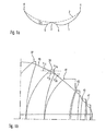
- FIG 2 an optical path diagram of a first embodiment of a projection optical system according to the present invention is depicted.
- the first group of lenses LG1 includes 3 lenses and has negative refractive power
- the second group of lenses LG2 includes 4 lenses and has positive refractive power
- the third group of lenses LG3 includes 5 lenses and has negative refractive power
- the first subgroup SG 4 1 of the fourth group of lenses LG4 includes. 7 lenses and has positive refractive power
- the second subgroup SG 4 2 of the fourth group of lenses LG4 includes 7 lenses and has positive refractive power.
- the projection optical system includes 26 lenses.
- the fourth group of lenses LG4 also includes an aperture stop in between the first and the second subgroup.
- lens parameters such as thickness of the lens, lens material, radius of the optical surface and diameter of the lens are listed in Table 1.
- an indication of a position of aspherical surfaces in the projection optical system and their parameters are given in Table 1.
- the first embodiment of a projection optical system contains 10 aspherical surfaces, all of which are disposed on overall concave lens surfaces.
- the projection optical system of the first embodiment is designed for imaging beams having 193 nm wavelength.
- Table 1 Surface Radius Thickness Lens material Diameter 0 0.000 32.000 112.16 1 0.000 0.798 128.31 2 1031.476 10.000 'SiO 2 HL' 130.89 3 275.197 10.624 133.40 4 -1229.209 10.000 'SiO 2 HL' 134.92 5 283.300 40.275 141.17 6 -103.631 70.049 'SiO 2 HL' 143.47 7 -183.668 1.000 220.25 8 -11585.541 27.459 'SiO 2 HL' 260.83 9 -473.064 1.000 266.76 10 677.737 51.525 'SiO 2 HL' 292.01 11 -420.149 1.000 294.30 12 299.
- the first group of lenses includes 2 meniscus lenses, one meniscus lens having a concave side facing the second object, one meniscus lens having a concave side facing in the direction of the first object.
- the first group of lenses has rather high negative refractive power, and requires only three lenses to achieve a strong divergence of the imaging beam bundle.
- a waist is formed by the third group of lenses LG3, which waist is required for Petzval correction.
- the third group of lenses LG3 imparts a strong divergence on the imaging beam.
- a first lens arrangement (“belly") is formed by the first and second group of lenses LG1 and LG2 and a second lens arrangement (“belly") is formed by the fourth group of lenses LG4.
- optical surfaces 45 and 48 i.e. a first surface of the second lens of the second subgroup and the second surface of the third lens of the subgroup together form a meniscus lens.
- a second surface 46 of the second lens and a first surface 47 of the third lens are disposed in very close proximity.
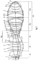
- FIG 3 an optical path diagram of a second embodiment of a projection optical system according to the present invention is depicted.
- the first group of lenses LG1 includes three lenses of negative refractive power
- the second group of lenses LG2 includes five lenses and has positive refractive power
- the third group of lenses LG3 includes three lenses of negative refractive power and forms the waist of the projection optical system.
- the first subgroup SG 4 1 of the fourth group LG4 includes four lenses and the second subgroup SG 4 2 of the fourth group of lenses LG4 includes 8 lenses, with the fourth lens group LG4 having positive refractive power.
- the fourth lens group LG4 further comprises an adjustable aperture stop, wherein the aperture stop comprises lamellae which, when changing a size of the aperture, can be moved on a lateral surface of a spherical shape.
- an adjustable aperture stop is provided the lamellae of which are shaped and arranged such that upon decreasing a size of the aperture, the lamellae move into the light path along a spherical shape. Therefore, the last lens of the first subgroup SG 4 1 and the first lens of the second subgroup SG 4 2 can be disposed in close vicinity to each other.
- the last lens of the third group LG3 and the first lens of the first subgroup SG 4 1 form a first doublet
- the second and third lens of the first subgroup SG 4 1 form a second doublet
- Lens surface 27 is a surface which is concave with respect to a direction of the second object, at which surface the imaging beams are subject to rather large angles of incidence and deflection. This lens surface has a strong correcting effect, in particular with respect to coma and spherical aberrations of the projection optical system.
- Lens surface 31 of the last lens of the first subgroup SG 4 1 and lens surface 34 of the first lens of the second subgroup SG 4 2 together form a meniscus lens.
- the last lens of the first subgroup is also of importance due to the large angle of deflection/incidence it imposes onto the imaging beam.
- an air lens is formed in between the first and the second lens of the second subgroup SG 4 2.
- the second lens of the second subgroup SG 4 2 has a high positive refractive power.
- lens parameters such as thickness of the lens, lens material, radius of the optical surface and diameter of the lens are listed in Table 3.
- an indication of a position of aspherical surfaces in the projection optical system and their parameters are given in Table 3.
- the second embodiment of a projection optical system contains 10 aspherical surfaces, all of which are disposed on overall concave lens surfaces.
- Table 4 Surface Radius Thickness Lens material Diameter 0 0.000 32.000 'AIRV193' 112.16 1 0.000 0.000 'AIRV193' 127.77 2 57573.384 8.000 'SiO 2 V' 128.94 3 243.811 13.262 'N2VP950' 132.25 4 -1090.143 9.354 'SiO 2 V' 134.84 5 466.146 37.485 'N2VP950' 141.26 6 -105.489 75.000 'SiO 2 V' 144.45 7 -148.914 0.700 'N2VP950' 214.83 8 -934.567 36.244 'SiO 2 V' 247.24 9 -274.035 0.700 'N2VP950' 254.54 10 1877.003 35.146 'SiO 2 V' 267.24 11 -433.158 0.700 'N2VP950' 268.74 12 34
Description
- The present invention relates to a projection optical system, in particular a projection optical system having a high numerical aperture.
- Lithographic processes are commonly used in the manufacture of semiconductor elements, such as integrated circuits (ICs), LSIs, liquid crystal elements, micropatterened members and micromechanical components.
- A projection exposure apparatus used for photolithography generally comprises an illumination optical system with a light source and a projection optical system. Light from the illumination optical system illuminates a reticle (a first object) having a given pattern and the projection optical system transfers an image of the reticle pattern (the first object), onto a region of a photo-sensitive substrate (a second object). The image of the reticle pattern may also be reduced in size by the projection optical system so as to produce a smaller image of the reticle pattern on the substrate.
- The trend to ever smaller and more sophisticated miniaturized devices places increasingly high demands on the projection exposure systems and thus projection optical systems used for the manufacture of these devices. In order to achieve better resolution in the exposure of substrates, projection optical systems with increased numerical apertures are being developed. In addition, a wavelength of light used for exposing substrates is decreased. Both of these changes bring about a whole range of new challenges in terms of a design of a projection optical system and a choice of lens materials.
- At present, illumination light of wavelengths shorter than 200 nm is predominantly used in the recently developed projection exposure systems. High quality lens materials suitable for use in projection optical system having a high numerical aperture and at a short wavelength tend to be in short supply and are generally associated with high cost.
- From the state of the art, projection optical systems with numerical apertures (on a substrate side of the projection optical system) up to 0.9 are known. Due to the need of correcting aberrations in the projection optical system, low angles of incidence and deflection of imaging beams (transferring an image of the first object onto the region of the second object) are generally preferred in such systems. This generally leads to projection optical systems comprising lenses of large diameter and a long distance between the first and the second object, or reticle and substrate, respectively. The large lens diameters and the long distance are, however, generally synonymous with a high mass of the lens material and thus high cost. As a consequence, the projection optical system tends to become rather heavy.
- Following the present trend and developing projection optical systems using illumination light wavelengths of shorter than 200 nm and with even higher numerical apertures whilst using the approach of increasing dimensions of the projection optical system would therefore inevitably lead to unfeasibly large dimensions of a projection optical system and lenses comprised therein.
-
EP-A-1 139 138 discloses a projection optical system for wave lengths shorter than 250 nm having plural aspherical lens surfaces. - It is an object of the present invention to provide a projection optical system having a high numerical aperture and a good imaging performance.
- In addition, it is an object of the present invention to provide a projection optical system having a compact design, in particular a short length between an object plane (or a first object) and an image plane (or a second object), and/or having lenses of relatively small diameter and/or a relatively small mass of lens material whilst providing a good imaging performance.
- This object is solved by providing a projection optical system having the features as defined in appended
independent claim 1, a projection exposure system having the features as defined in appended independent claim 7, and a method of manufacturing a microstructured device having the features as defined in appended independent claim 8. Advantageous embodiments are defined in the appendeddependent claims 2 to 6. - In preferred embodiments, a sum of the absolute values of the total refractive powers of the first, second, third and fourth groups is a maximum value (a maximum value in particular in comparison to values obtainable by other possible divisions into groups).
- Lens, as used herein, relates to a single lens element, not a optical system comprised of a plurality of lens elements.
- The projection optical system is preferably a purely refractive or dioptric projection optical system, i.e. does not comprise reflective optical elements such as mirrors.
- The arrangement of a negative lens group followed by a positive lens group, followed by a negative lens group, followed by a positive lens group in the direction of the optical axis (the given order starting at the first object) of the projection optical system according to the present invention results in what is generally referred to as a "single waist type" projection optical system. The waist indicates a constriction or a minimum diameter of the projection optical system. In particular, the waist is formed by lenses of the third group of lenses.
- According to an embodiment, the following relation is fulfilled:

wherein: - y
- is half a diameter in mm of a maximum image field imaged by the projection optical system,
- NA
- is a maximum numerical aperture on a side of the second object,
- Φi
- is a refractive power in mm-1 of the ith lens,
- k
- is a total number of lenses of the projection optical system,
- and V1
- is greater than 0.045.
- In exemplary embodiments of the present invention, V1 is greater than 0.055.
- Herein, lenses having comparatively high refractive powers are used and thus an imaging beam used to transfer an image of the first object into a region of the second object may be subject to rather large angles of deflection/incidence. The use of lenses having relatively high refractive powers enables a compact design of the projection optical system, in particular a relatively short distance between the first and the second object as well as use of lenses with a comparatively small diameter. For instance, distances between the first object and the second object as short as about 1000 mm can be realized. A largest diameter of a lens in the projection optical system according to the present invention may be smaller than about 300 mm.
- A suitable measure for the extent to which high refractive power lenses are used in the projection optical system is the mean refractive power Φm of all lenses in the projection optical system, which is given by the following equation:

with Φi and k as defined above. - A further factor which is important in the design of projection optical systems is the etendue E, which can be expressed as:

- Thus, equation (1) can also be written as:

- The inventors of the present inventions found that advantageous, compact designs of projection optical systems with good imaging properties can be realised when a product of Φm and E is greater than 0.045, in particular greater than 0.055, as already mentioned above.
- According to an embodiment, the following relation is fulfilled:

wherein: - y, NA and k
- are as defined above,
- δi1
- is a maximum deflection angle of imaging beams at a first optical surface of the ith lens,
- δi2
- is a maximum deflection angle of imaging beams at a second optical surface of the ith lens,
- According to a further exemplary embodiment, V2 is greater than 5.
- In a simplified, expression, this relation can be described as:

wherein δm is a mean value of the absolute values of the maximum deflection angles of the imaging beams at the surfaces of the lenses of the projection optical system, as defined by
in equation (5). - A projection optical system having good imaging properties with deliberate use of at least one of high incidence angles and high deflection angles is quite in contrast to a general teaching that in an optical system, the smaller an angle is at which a light beam is incident onto each lens surface, the less aberrations are generated and the looser a tolerance becomes.
- In particular with regard to the use of high refractive power lenses and the occurrence of high angles of incidence/deflection in the projection optical system according to the present invention, a correction of imaging errors such as aberrations can be advantageously carried out by the use of aspherical surfaces in the projection optical system. Imaging errors are defined herein as any deviation of an imaging characteristic from an optimum value of the imaging characteristic.
- According to the present invention, each of at least five lenses of the plurality of lenses has at least one aspherical surface. According to an exemplary embodiment, the projection exposure system does not contain more than 10 aspherical surfaces.
- As used herein, the term "aspherical surface" is to be understood as referring to aspherical surfaces in which a maximum axial distance between the aspherical surface and a best fitting sphere is 2 µm or more. This definition serves to exclude spherical surfaces with unintended deformations as well as aspherical surface parts typically introduced after the manufacture of the lens/projection optical system for correction of aberrations which are generally due to the manufacturing process rather than inherent to the particular design of the projection optical system. For the purpose of describing the degree to which a surface is aspherical, an (imaginary) ideal spherical shape or best fitting sphere is chosen such that a centre and a periphery of the aspherical surface are positioned on the best fitting sphere and then an axial distance between the best fitting sphere and the aspherical surface determined. A radial surface profile and a best fitting sphere chosen in accordance with the above is illustrated in
Figure 1a . The influence of aspherical surfaces on aberrations, in particular the parameters aspherical surfaces offer for enhancing an imaging performance, has been extensively studied, and documented in the literature. - According to the present invention, an axial distance between the aspherical surface and a best fitting sphere is more than about 300 µm and less than about 500 µm. As described above, the best fitting sphere is chosen such that a centre and a periphery of the aspherical surface are positioned on the best fitting sphere. The above values indicate that the lens surfaces used are comparatively strongly aspherical, i.e. that a departure from a best fitting sphere is comparatively large. Such aspherical surfaces are preferably positioned in the first group of lenses and/or, if an aperture stop is provided in the projection optical system, close to the aperture stop.
- The use of aspherical lenses in the projection optical system helps to reduce the length of the projection optical system and the required amount of lens material as well as to improve an imaging performance.
- According to a further exemplary embodiment, an absolute value of a maximum change of curvature of the aspherical surface(s) (dc/ds) is greater than 300 m-2.
- In exemplary embodiments of the projection optical system, each of the at least five aspherical surfaces having effective diameters Das has a centre of curvature of the best fitting sphere disposed on a side of the aspherical surface facing away from the lens carrying the aspherical surface, wherein Das is 0.2 times a design-distance LD between the first object and the second object. In other words, an aspherical surface is preferably disposed on an surface of a lens which surface has an overall concave shape.
- Manufacturing lenses having an aspherical surface with an axial distance to the best fitting sphere as large as defined above places high demands on both a manufacturing process itself as well as on an optical testing of a manufactured aspherical surface. For the testing of such surfaces, interferometric techniques are preferably used. For interferometric measurement of an aspherical surface, a wave front of a reference wave front, which the aspherical wave front is compared to, needs to be made aspherical in order to achieve an ideal fit of the wave front to be measured. For this purpose, it is necessary to develop so-called "null-optics" or "null-system", which are capable of generating a suitable aspherical wave front for interferometrically measuring the aspherical surface of the lens. Aspherical surfaces having large deformations and high values in terms of Zernike coefficients require interferometers having refractive systems of such complexity that these refractive systems become virtually impossible and/or economically unfeasible to produce.
- A strong deformation of aspherical surfaces generally requires computer-generated holograms. i.e. diffractive systems, to be used in interferometric measurements of the aspherical surfaces. Computer-generated holograms (CGHs), if combined appropriately with a small number of refractive elements or even by themselves, are capable of generating nearly any kind of wave front. However, also computer-generated holograms are subject to practical limits in terms of manufacturability, in particular with respect to their size, due to the limitations imposed by the techniques used in the manufacture of CGHs, such as electron beam, laser beam and photolithographic techniques.
- In accordance with the present invention, this problem can be overcome or at least alleviated by placing aspherical surfaces in the projection optical system such that the aspherical surfaces are located on overall concave surfaces of the lenses, as described above. An overall concave surface of a lens is a surface which has a centre of curvature of the best fitting sphere disposed on a side of the aspherical surface facing away from the lens carrying the aspherical surface, as defined above. According to a further exemplary embodiment, all aspherical surfaces which are part of lenses having a maximum diameter larger than about 200 mm are located on overall concave surfaces. According to a further exemplary embodiment, the aspherical surfaces placed in accordance with the above have best fitting spheres associated with them which best fitting spheres have a radius greater than 300mm and/or smaller than 2000 mm. The lower limit is determined by factors relating to manufacturing and the upper limit determined by a largest feasible length of a "null optics" used in interferometric measuring the aspherical surface.
- Projection optical systems having aspherical and spherical surfaces at which angles of deflection/incidence are rather large allow to use relatively small amounts of glass, in particular in terms of a mass of glass, and thus help to decrease cost and weight of the projection optical system.
- According to an embodiment, the following relation is fulfilled:

wherein: - y and NA are as defined above and wherein GD is a sum of all axial thickness of the lenses, wherein the axial thickness of each lens represents a thickness of the lens at a location on the optical axis, and wherein V4 is smaller than 40.
- According to an exemplary embodiment, V4 is smaller than 35.
- GD is a suitable indicator of the amount, in particular in terms of mass, of lens material used in the projection optical system and thus cost associated with the lens material.
- In exemplary embodiments, the projection optical system comprises an aperture stop disposed between two lenses of the fourth group of lenses. In those embodiments, the fourth group of lenses consists of a first sub-group of lenses in between the first object (or: the third group of lenses, more precisely) and the aperture stop and a second sub-group of lenses in between the aperture stop and the second object.
- According to further exemplary embodiments , the following condition is fulfilled:

wherein - f1
- is a focal length of a lens unit consisting of the first, second and third group as well as the first sub-group of the fourth group,
- f2
- is a focal length of the second sub-group of the fourth group,
- β
- is a magnification of the projection optical system.
- In alternative embodiments, the following condition is fulfilled:

with f1, f2 and β as defined above. - The mismatch of the focal length of the lens unit comprising all lenses in between the aperture stop and the first object, and focal length of the second sub-group of the fourth group of lenses which comprises all lenses in between the aperture stop and the second object, serves to create an afocal projection optical system.
- According to exemplary embodiments of the projection optical system, the following condition is fulfilled:

wherein - LD
- is a design-distance between the first object and the second object,
- Dbeam
- is a maximum diameter of a beam bundle,
- NA
- is the maximum numerical aperture on the side of the second object, and
- FD
- is a maximum field-height of the first object.
- The term "design distance" or "design length" as used herein stands for a distance between the first object and the second object in an operating or exposure mode, i.e. as foreseen by the design of the projection optical system when both the first and the second objects are in focus.
- According to exemplary embodiments of the projection optical system of the present invention, a radial surface profile of an aspherical surface has at most one point of inflection of curvature. According to a further exemplary embodiment, a radial surface profile of at most one aspherical surface has a point of inflection of curvature in an optically effective area of the aspherical surface. Since an aspherical surface is generally rotationally symmetrical, one point of inflection, as used herein, would encompass embodiments wherein the point of inflection extends in a given shape, in particular a circle, across the surface of the aspherical surface. The radial surface profile shown in
Figure 1a , for instance, would fall within the meaning of an aspherical surface having just one point of inflection. - According to an exemplary embodiment, a focal length of the projection optical system is shorter than 250 mm. The choice of this particular focal length enables the realisation of good telecentric properties of the projection optical system, in particular on a side of the second object.
- In exemplary embodiments of the projection optical system , at least one lens in the second sub-group of the fourth group of lenses is a lens of positive refractive power and the at least one lens fulfils the following conditions:

wherein - i1
- is a maximum angle of incidence of an imaging beam on a first surface of the at least one lens,
- i2
- is a maximum angle of incidence of the imaging beam on a second surface of the at least one lens,
- u1i
- is a maximum angle formed between the imaging beam and the optical axis at the first surface outside of the at least one lens,
- u2i
- is a maximum angle formed between the imaging beam and the optical axis at the second surface inside of the at least one lens,
- u1o
- is a maximum angle formed between the imaging beam and the optical axis at the first surface inside of the at least one lens,
- u2o
- is a maximum angle formed between the imaging beam and the optical axis at the second surface outside of the at least one lens, and
- f4p
- focal length of the at least one lens.
- The angles referred to above are shown schematically in
Figure 1b The restriction with respect to the focal length of the at least one lens serves to exclude trivial cases of plane parallel plates. - According to an exemplary embodiment, the first group of lenses is comprised only of lenses having negative refractive power, wherein one of the lenses of the first group is a meniscus lens having a convex surface facing the first object.
- According to exemplary embodiments of the present invention, the second group of lenses is comprised only of lenses having positive refractive power, wherein at least one of the lenses of the second group has a (overall) concave, aspherical surface. According to a further exemplary embodiment of the present invention, the second group of lenses comprises at least three lenses.
- According to an exemplary embodiment , at least one lens of the third group of lenses has an aspherical surface.
- According to further exemplary embodiments , the third group of lenses is comprised only of lenses having negative refractive power.
- According to further exemplary embodiments , the third group of lenses comprises three or more lenses of negative refractive power. According to further exemplary embodiments, a lens having positive refractive power is disposed between two lenses having negative refractive power in the third group of lenses.
- Embodiments of the projection optical system have proven to be advantageous when the first sub-group of the fourth group of lenses comprises at least one lens of negative refractive power, which lens has a first and a second surface and fulfils the following condition:

wherein - c11
- is a curvature of the first surface of the at least one lens and
- c12
- is a curvature of the second surface of the at least one lens.
- According to a further exemplary embodiment, the first sub-group of the fourth group of lenses comprises two to four lenses of positive refractive power.
- According to a further exemplary embodiment, the first sub-group of the fourth group of lenses (also) comprises at least one lens of negative refractive power having a first and a second surface, which lens fulfils the following condition:

wherein - c21
- is a curvature of the first surface of the at least one lens and
- c22
- is a curvature of the second surface of the at least one lens.
- According to a further exemplary embodiment , the second sub-group of the fourth group of lenses comprises only one lens having negative refractive power.
- According to a further exemplary embodiment, the second sub-group of the fourth group of lenses comprises a lens having negative refractive power disposed adjacent to a lens having positive refractive power, with the lens having positive refractive power being positioned closer to the second object (than the lens having negative refractive power), and wherein the negative lens fulfils the following condition:

wherein - c31
- is a curvature of the first surface of the at least one lens and
- c32
- is a curvature of the second surface of the at least one lens.
- According to further exemplary embodiments , the second sub-group of the fourth group of lenses comprises a lens having positive refractive power disposed adjacent to a lens having negative refractive power, with the lens having negative refractive power being positioned closer to the second object, and wherein the negative lens fulfils the following condition:

wherein - c41
- is a curvature of the first surface of the at least one lens and
- c42
- is a curvature of the second surface of the at least one lens.
- According to exemplary embodiments the second sub-group of the fourth group of lenses comprises no less than two and no more than four positive meniscus lenses having their concave surfaces facing the second object. This embodiment is helpful in realising an aplanatic design.
- In exemplary embodiments, the first group of lenses contains a maximum of two aspherical lenses, the second group of lenses contains a maximum of two aspherical lenses, the third group of lenses contains a maximum of one aspherical lens, the first sub-group of the fourth group of lenses contains a maximum of three aspherical lenses, and the second sub-group of the fourth group of lenses contains a maximum of three aspherical lenses. According to an exemplary embodiment of the present invention, each of those aspherical lenses has only one aspherical surface.
- According to an exemplary embodiment , in the second sub-group of the fourth group of lenses, any lens having an aspherical surface has the aspherical surface on a side of the lens facing the second object.
- According to a further exemplary embodiment, in the first group of lenses, any lens having an aspherical surface has the aspherical surface on a side of the lens facing the first object.
- It is advantageous if in embodiments of the projection optical system, the following condition is fulfilled:

- GD
- is the sum of axial thickness of all the lenses, as defined above,
- LD
- is the design-distance between the first object and the second object.
- The choice of a suitable lens material or suitable lens materials depends largely on the wavelength of light used in the imaging beams and thus for exposure of the second object. Desirably, the lens material is not prone to significant radiation-induced damage such as increased transmission or a change in refractive index caused by phenomena such as compaction and rarefaction and should ideally exhibit low birefringence, both stress induced and intrinsic birefringence.
- An appropriate choice and placement of lens material(s) allows correction of chromatic aberrations in the projection optical system and thus somewhat alleviates the demands placed on the optical design of the projection optical system.
- Fused silica, in particular synthetic fused silica, is the most common material used in projection exposure systems employing short wavelengths for exposure, such as 193 nm. The susceptibility of fused silica materials to UV-induced damage is correlated with the materials' chemical and physical properties, which, in turn, are closely linked to methods of manufacturing and/or treating the material(s). Upon exposure to high intensity radiation, exposed areas of a lens of a given material have been found to undergo a change in density, in particular densification or rarefaction. The change in density of an exposed area in a lens in a projection exposure apparatus can generally be assumed to have a detrimental effect on the optical properties of the lens. In particular, wavefront distortion is indicative of densification or rarefaction and can be measured and determined by suitable interferometric methods, for example. An increase in density, for instance, of the lens material shortens the physical path through the material, but also alters the refractive index, which is generally increased to a greater extent, so that the net effect is an increase in the optical path. For rarefaction phenomena, the opposite applies.
- A lens material that is transparent to UV-radiation and which has, at least so far, not been found to be subject to such structural alterations that are associated with changes in optical properties is calcium fluoride, CaF2. Therefore, calcium fluoride is a suitable material at wavelengths in the deep ultraviolet, such as 193 nm and 157 nm, which are typically used. In addition, other earth alkaline fluoride materials are suitable lens materials with properties similar to that of calcium fluoride. Due to radiation-induced damage found in silica materials, calcium fluoride is the lens material of choice when it comes to prolongation of a life-time of the projection optical system and thus the corresponding projection exposure system. However, for calcium fluoride to be suitable for use in optical lenses, it needs to be in the form of single crystals which are not only costly but also technically difficult to manufacture so that the resulting limited supply somewhat constrains its practical use.
- In one embodiment, all lenses are made of calcium fluoride. In an alternative embodiment, all lenses are made of silica, in particular fused silica.
- In further embodiments, one or more lens materials, in particular crystalline materials, may be used as lens materials. In those embodiments, the lens materials/crystalline materials may comprise a fluoride material, such as calcium fluoride, barium fluoride and other suitable fluorides.
- According to exemplary embodiments of the projection optical system, one or more of the four lenses disposed closest to the second object are made of a fluoride material, wherein a crystal orientation of the fluoride material in the one or more lenses with respect to the optical axis is the same in two or more lenses. For instance, all four lenses may be made of (110) fluorite material, wherein the particular chosen crystal lattice is arranged in one predefined orientation with respect to the optical axis for all four lenses.
- According to a further exemplary embodiment, one ore more lenses of the third group of lenses is made of a fluoride material in order to help prolong the life-time of the projection optical system.
- According to further exemplary embodiments , one or more lenses of the second group of lenses is made of a fluoride material. Preferably, one of the positive lenses in the fourth group of lenses is made of a fluoride material. Those embodiments are particularly advantageous in terms of a correction of chromatic aberrations, in particular in terms of a reduction of a lateral chromatic aberration.
- When calcium fluoride or another fluoride material is used in one or more lenses of the projection optical system, preferably, diameter, thickness and crystal orientation of the fluoride used in the lenses are chosen such that a loss in contrast due to intrinsic birefringence is less than 0.5 %.
- The aperture stop used in exemplary embodiments is preferably adjustable. In order to enable very compact designs of projection optical systems, exemplary embodiments of the present invention have an adjustable aperture stop wherein an axial position of an aperture formed by the aperture stop varies with a size of the aperture, wherein the axial position of the aperture is defined by an intersection of a plane defined by the aperture, i.e. a plane containing the aperture, and the optical axis.
- According to exemplary embodiments , the adjustable aperture stop comprises lamellae having an essentially planar shape. Alternatively, the adjustable aperture stop may comprise lamellae essentially all of which have an identical spherical shape. An example of such an aperture is described in
US 6,445,510, filed on October 4, 2000 , to the same Assignee . Apertures wherein the axial position of the aperture varies with the size of the aperture are advantageously used to enable a lens in front of the aperture and a lens behind the aperture (in the direction of light propagating in a direction from the first to the second object) being disposed very closely together, i.e. to reduce a necessary spacing in between these two lenses. This ability creates further possibilities in the design of projection optical system since the previous requirements for a large spacing in between lenses directly adjacent to the aperture stop are no longer given. - The projection optical system generally has a high a numerical aperture of the projection optical system on a side of the second object, in exemplary embodiments the numerical aperture is greater than 0.91.
- According to further exemplary embodiments , the fourth lens group comprises at least one pair of immediately adjacent lenses, wherein a first lens of the pair of lenses has a first and a second surface and a second lens of the pair of lenses has a third surface and a fourth surface, and wherein the first, second, third and fourth surfaces are disposed along the optical axis in this order, and wherein the following conditions are fulfilled:

wherein - d
- is a maximum distance between the second surface and the third surface,
- c51
- is a curvature of the first surface,
- c52
- is a curvature of the fourth surface, and
- V5 = 15 mm, V6 = 10 , V7 = 0.003 mm-1.
- According to further exemplary embodiments, V5 = 10 mm and/or V6 = 15 and/or V7 = 0.004 mm-1.
- In those embodiments, the first surface and the fourth surface, i.e. two surfaces of two different lenses, practically form a meniscus lens, in particular the optical surfaces of a meniscus lens. This arrangement has proven to be advantageous for the imaging properties of the projection optical system in particular in projection optical systems of a compact design, i.e. a short design length between the first and the second object and relatively small maximum diameters of the lenses comprised in the projection optical system.
- The projection optical system according to the present invention enables the realization of a compact design, in particular a short design length between the first and the second object and comparatively small maximum diameters of lenses, as well as low chromatic aberrations.
- In the following, embodiments of the present invention are explained in further detail with reference to Figures, wherein:
- Figure 1a
- is a schematic illustration of a radial surface profile of an aspherical surface of a lens;
- Figure 1b
- is an illustration of angles of incidence and deflection on two surfaces of a lens;
- Figure 2
- is an optical path diagram of a first embodiment of a projection optical system according to the present invention; and
- Figure 3
- is an optical path diagram of a second embodiment of a projection optical system according to the present invention.
-
Figure 1a shows a schematic representation of a radial surface profile of anaspherical surface 1 with a corresponding bestfitting sphere 2 fitted thereto. Point 3 indicates the centre of the aspherical surface and points 4 indicate the periphery of the aspherical surface.Point 5 indicates a point of inflection of the curvature of the aspherical lens. Since the depicted aspherical surface is rotationally symmetrical, point ofinflection 5 extends in a circle across the aspherical surface, such that the aspherical surface, in the terminology used herein, would be regarded as having only one point of inflection. Δ indicates a departure from the best fitting sphere, i.e. an axial distance between the aspherical surface and the ideal sphere best fitted thereto. -
Figure 1b shows an excerpt of a lens of an embodiment of a projection optical system according to the present invention, wherein - u1i
- as the maximum angle formed between the imaging beam and the optical axis at the first surface outside of the lens,
- u2i
- as the maximum angle formed between the imaging beam and the optical axis at the second surface inside of the lens,
- u1o
- as the maximum angle formed between the imaging beam and the optical axis at the first surface inside of the lens,
- u2o
- as the maximum angle formed between the imaging beam and the optical axis at the second surface outside of the lens,
- In
Figure 2 , an optical path diagram of a first embodiment of a projection optical system according to the present invention is depicted. As indicated by the brackets, the first group of lenses LG1 includes 3 lenses and has negative refractive power, the second group of lenses LG2 includes 4 lenses and has positive refractive power, the third group of lenses LG3 includes 5 lenses and has negative refractive power, thefirst subgroup SG 41 of the fourth group of lenses LG4 includes. 7 lenses and has positive refractive power, thesecond subgroup SG 42 of the fourth group of lenses LG4 includes 7 lenses and has positive refractive power. Overall, the projection optical system includes 26 lenses. The fourth group of lenses LG4 also includes an aperture stop in between the first and the second subgroup. - Detailed information on lens parameters such as thickness of the lens, lens material, radius of the optical surface and diameter of the lens are listed in Table 1. In addition, an indication of a position of aspherical surfaces in the projection optical system and their parameters are given in Table 1. An aspherical surface can be characterised by the following equation:

wherein - r
- radius of curvature in the apex of the aspherical surface (paraxial curvature),
- h
- distance of a point on the aspherical surface from the optical axis (or height of the aspherical surface from the optical axis),
- p(h)
- is the sag of the surface in axial direction, i.e. a distance along the direction of the optical axis from a tangent plane to a vertex of the aspheric surface,
- K
- conical coefficients and
- As evident from Table 1, the first embodiment of a projection optical system contains 10 aspherical surfaces, all of which are disposed on overall concave lens surfaces. The projection optical system of the first embodiment is designed for imaging beams having 193 nm wavelength.
Table 1 Surface Radius Thickness Lens material Diameter 0 0.000 32.000 112.16 1 0.000 0.798 128.31 2 1031.476 10.000 'SiO2HL' 130.89 3 275.197 10.624 133.40 4 -1229.209 10.000 'SiO2HL' 134.92 5 283.300 40.275 141.17 6 -103.631 70.049 'SiO2HL' 143.47 7 -183.668 1.000 220.25 8 -11585.541 27.459 'SiO2HL' 260.83 9 -473.064 1.000 266.76 10 677.737 51.525 'SiO2HL' 292.01 11 -420.149 1.000 294.30 12 299.116 48.633 'SiO2HL' 293.24 13 -8515.515 1.000 289.64 14 165.992 36.044 'SiO2HL' 250.25 15 274.140 11.842 239.88 16 351.874 66.976 'SiO2HL' 236.90 17 113.149 27.726 157.71 18 159.540 25.025 'SiO2HL' 149.32 19 1008.355 21.895 142.58 20 -152.924 10.000 'SiO2HL' 139.65 21 155.990 40.933 131.75 22 -100.703 10.000 'SiO2HL' 132.11 23 2203.235 14.695 156.09 24 -297.997 10.000 'SiO2HL' 159.08 25 630.640 6.141 185.24 26 1026.503 32.293 'SiO2HL' 195.25 27 -289.676 1.000 204.47 28 -446.572 45.387 'SiO2HL' 209.56 29 -141.103 1.000 218.42 30 1251.841 11.400 'SiO2HL' 239.86 31 278.497 19.855 245.36 32 696.209 11.400 'SiO2HL' 247.88 33 473.704 1.000 256.80 34 330.852 35.966 'SiO2HL" 271.36 35 4411.497 1.000 274.35 36 597.458 70.550 'SiO2HL' 283.42 37 -250.280 10.735 284.92 38 -211.754 11.400 'SiO2HL' 283.44 39 -367.920 1.022 292.91 40 0.000 10.000 'SiO2HL' 291.79 41 0.000 -6.209 292.85 STO 0.000 7.653 291.65 43 336.127 77.330 'SiO2HL' 300.00 44 -352.638 21.376 297.91 45 -240.225 12.078 'SiO2HL' 295.04 46 -771.704 1.000 299.02 47 2064.728 45.378 'SiO2HL' 297.01 48 -368.429 1.000 295.99 49 128.930 44.704 'SiO2HL' 221.85 50 222.899 1.000 208.75 51 142.963 65.247 'SiO2HL' 191.87 52 1352.559 1.704 139.24 53 547.791 28.608 'SiO2HL' 128.60 54 784.739 2.695 85.44 55 0.000 8.000 'SiO2HL' 76.26 56 0.000 6.000 64.01 57 0.000 0.000 28.04 Aspherical surfaces Surface 2 K: 0.000000 A: 0.179210E-06 B:-.183601E-10 C: 0.166069E-14 D: -.294001E-18 E: 0.883907E-22 F:-.163553E-25 G: 0.125411E-29 H: 0.000000E+00 J: 0.000000E+00 Surface 4 K: 0-000000 A: 0.766695E-07 B: 0.781019E-11 C: -.117892E-14 D: 0.172623E-18 E: -.547425E-22 F: 0.100176E-25 G: -.755382E-30 H: 0.000000E+00 J: 0.000000E+00 Surface 15 K:0.000000 A: 0.136312E-07 B: -.992470E-13 C: -.345322E-17 D: 0.206018E-21 E: -.443982E-25 F: 0.210515E-29 G: -.746796E-34 H: 0.060000E+00 J: 0.000000E+00 Surface 21 K: 0.000000 A: -.225645E-07 B: -.505339E-11 C: -.133289E-15 D: 0.366375E-19 E: -.737639E-23 F: 0.159483E-26 G: -.149942E-30 H: 0.000000E+00 J: 0.000000E+00 Surface 28 K: 0.000000 A: -.304506E-07 B: 0.297866E-12 C: 0.296080E-16 D: .224605E-20 E: 0.320081E-24 F: -.176893E-28 G: 0.398957E-33 H: 0.000000E+00 J: 0.000000E+00 Surface 33 K: 0.000000 A: 0.893991E-08 B: -.381137E-13 C: -.103082E-18 D: -.345423E-22 E: -.117217E-25 F: 0.129547E-29 G: .287147E-34 H: -.311364E-39 J: 0.000000E+00 Surface 38 K: 0.000000 A: 0.346098E-08 B: 0.239948E-13 C: 0.837128E-18 D: -.842934E-22 E: 0.107693E-25 F: -.727735E-30 G: 0.394912E-34 H: -.105875E-38 J: 0.000000E+00 Surface 45 K: 0.000000 A: -.240529E-09 B: -.193202E-12 C: 0.332296E-17 D: 0.154348E-21 E: .251137E-25 F: 0.174127E-29 G: -.574851E-34 H: 0.814458E-39 J: 0.000000E+00 Surface 50 K: 0.000000 KC: 100 A: 0.664683E-08 B: 0.803136E-12 C: -.257217E-16 D: 0.827303E-20 E: -.204820E-23 F: 0.261228E-27 G: -.194941E-31 H: 0.632538E-36 J: 0.000000E+00- Surface 52 K: 0.000000 A: 0.273186E-07 B: 0.812461E-11 C: -.105427E-14 D: 0.485865E-19 E: 0.267241E-22 F: -.580414E-26 G: 0.370026E-30 H: .782824E-35 J: 0.000000E+00 - As apparent from
Figure 2 , the first group of lenses includes 2 meniscus lenses, one meniscus lens having a concave side facing the second object, one meniscus lens having a concave side facing in the direction of the first object. The first group of lenses has rather high negative refractive power, and requires only three lenses to achieve a strong divergence of the imaging beam bundle. - A waist is formed by the third group of lenses LG3, which waist is required for Petzval correction. The third group of lenses LG3 imparts a strong divergence on the imaging beam. A first lens arrangement ("belly") is formed by the first and second group of lenses LG1 and LG2 and a second lens arrangement ("belly") is formed by the fourth group of lenses LG4. The third and fourth lens of the
first subgroup SG 41 of the fourth group of lenses LG4, both of which are meniscus lenses having a concave surface facing in the direction of the second object, provide strong deflection angles. In thesecond subgroup SG 42 of the fourth group of lenses LG4,optical surfaces 45 and 48, i.e. a first surface of the second lens of the second subgroup and the second surface of the third lens of the subgroup together form a meniscus lens. A second surface 46 of the second lens and afirst surface 47 of the third lens are disposed in very close proximity. - In Table 2, characteristic parameters of the first embodiment of the present invention are listed.
Table 2 NA 0.95 E [mm] 26.638 ϕm [mm-1] 2.29e-3 ϕm .E 0.061 δm in ° 14.73 sin(δm).E [mm] 6.77 GD [mm] 885.5 GD /E 33.2 dc/ds max in m-2 574 - As can be seen from Tables 1 and 2, a first, second, third and fourth aspect of the invention are realised in the first embodiment.
- In
Figure 3 , an optical path diagram of a second embodiment of a projection optical system according to the present invention is depicted. As indicated by the brackets, the first group of lenses LG1 includes three lenses of negative refractive power, the second group of lenses LG2 includes five lenses and has positive refractive power, the third group of lenses LG3 includes three lenses of negative refractive power and forms the waist of the projection optical system. Thefirst subgroup SG 41 of the fourth group LG4 includes four lenses and thesecond subgroup SG 42 of the fourth group of lenses LG4 includes 8 lenses, with the fourth lens group LG4 having positive refractive power. The fourth lens group LG4 further comprises an adjustable aperture stop, wherein the aperture stop comprises lamellae which, when changing a size of the aperture, can be moved on a lateral surface of a spherical shape. Thus, rather than providing an aperture which is fixed at a certain position of the optical axis during adjustment, an adjustable aperture stop is provided the lamellae of which are shaped and arranged such that upon decreasing a size of the aperture, the lamellae move into the light path along a spherical shape. Therefore, the last lens of thefirst subgroup SG 41 and the first lens of thesecond subgroup SG 42 can be disposed in close vicinity to each other. The last lens of the third group LG3 and the first lens of thefirst subgroup SG 41 form a first doublet, and the second and third lens of thefirst subgroup SG 41 form a second doublet. Lens surface 27 is a surface which is concave with respect to a direction of the second object, at which surface the imaging beams are subject to rather large angles of incidence and deflection. This lens surface has a strong correcting effect, in particular with respect to coma and spherical aberrations of the projection optical system. Lens surface 31 of the last lens of thefirst subgroup SG 41 andlens surface 34 of the first lens of thesecond subgroup SG 42 together form a meniscus lens. The last lens of the first subgroup is also of importance due to the large angle of deflection/incidence it imposes onto the imaging beam. In between the first and the second lens of thesecond subgroup SG 42, an air lens is formed. The second lens of thesecond subgroup SG 42 has a high positive refractive power. - Detailed information on lens parameters such as thickness of the lens, lens material, radius of the optical surface and diameter of the lens are listed in Table 3. In addition, an indication of a position of aspherical surfaces in the projection optical system and their parameters are given in Table 3. As evident from Table 3, the second embodiment of a projection optical system contains 10 aspherical surfaces, all of which are disposed on overall concave lens surfaces.
- In Table 4, characteristic parameters of the second embodiment of the present invention are listed.
Table 3 Surface Radius Thickness Lens material Diameter 0 0.000 32.000 'AIRV193' 112.16 1 0.000 0.000 'AIRV193' 127.77 2 57573.384 8.000 'SiO2V' 128.94 3 243.811 13.262 'N2VP950' 132.25 4 -1090.143 9.354 'SiO2V' 134.84 5 466.146 37.485 'N2VP950' 141.26 6 -105.489 75.000 'SiO2V' 144.45 7 -148.914 0.700 'N2VP950' 214.83 8 -934.567 36.244 'SiO2V' 247.24 9 -274.035 0.700 'N2VP950' 254.54 10 1877.003 35.146 'SiO2V' 267.24 11 -433.158 0.700 'N2VP950' 268.74 12 340.474 28.340 'SiO2V' 263.65 13 1177.958 0.700 'N2VP950' 260.39 14 180.585 34.561 'SiO2V' 242.61 15 206.758 0.700 'N2VP950' 224.36 16 155.939 75.000 'SiO2V' 216.75 17 281.771 15.027 'N2VP950' 171.22 18 15953.616 8.000 'SiO2V' 166.15 19 98.432 77.068 'N2VP950' 137.11 20 -111.308 8.019 'SiO2V' 128.52 21 -702.509 18.031 'N2VP950' 136.29 22 -138.076 8.362 'SiO2V' 137.45 23 416.972 18.694 'N2VP950' 158.20 24 -11234.170 41.874 'SiO2V' 170.34 25 -150.893 0.700 'N2VP950' 182.81 26 -1297.101 8.000 'SiO2V' 199.72 27 253.311 21.736 'N2VP950' 215.55 28 1068.917 45.071 'SiO2V' 223.06 29 -236.445 0.700 'N2VP950' 231.38 30 244.024 37.656 'SiO2V' 298.50 31 555.375 27.303 'N2VP950' 297.24 32 0.000 -18.174 'N2VP950' 298.02 33 360.544 15.000 'SiO2V' 302.13 34 221.881 36.472 'N2VP950' 295.96 35 488.301 77.125 'SiO2V' 299.83 36 -279.915 0.700 'N2VP950' 303.00 37 187.876 53.225 'SiO2V' 285.84 38 489.307 0.700 'N2VP950' 278.37 39 163.275 44.194 'SiO2V' 246.77 40 325.398 0.700 'N2VP950' 232.49 41 140.866 60.717 'SiO2V' 200.93 42 235.724 2.997 'N2VP950' 146.44 43 232.815 16.671 'SiO2V' 142.60 44 582.777 6.772 'N2VP950' 127.85 45 375.408 11.293 'SiO2V' 100.07 46 687.655 3.099 'N2VP950' 84.48 47 0.000 9.375 'SiO2V' 73.36 48 0.000 5.000 'AIRV193' 58.93 49 0.000 0.000 28.04 Aspherical surfaces Surface 2 K: 0.000000 KC: 100 A: 0.218716E-06 B: -.248776E-10 C: 0.185358E-14 D: -.161759E-18 E: 0.192307E-23 F: 0.547379E-28 G: 0.000000E+00 H: 0.000000E+00 J: 0.000000E+00 Surface 4 K: 0.000000 KC: 100 A: 0.290942E-07 B: 0.126121E-10 C: -.105557E-14 D: 0.362305E-19 E: 0.842431E-23 F: -.416292E-27 G: 0.000000E+00 H: 0.000000E+00 J: 0.000000E+00 Surface 8 K: 0.000000 KC : 100 A: -.150691E-08 B: 0.212074E-12 C: 0.518282E-17 D: 0.216329E-22 E: -.516324E-26 F: 0.333908E-31 G: 0.000000E+00 H: 0.000000E+00 J: 0.000000E+00 Surface 17 K: 0.000000 KC: 100 A: -.377475E-07 B: 0.114027E-11 C: 0.292881E-16 D: -.547743E-20 E: 0.158504E-24 F: 0.734629E-29 G: 0.000000E+00 H: 0.000000E+00 J: 0.000000E+00 Surface 21 K: 0.000000 KC: 100 A: -.113618E-08 B: -.309117E-11 C: -.571100E-15 D: 0.250974E-19 E: 0.271018E-23 F: .232236E-27 G: 0.000000E+00 H: 0.000000E+00 J: 0.000000E+00 Surface 24 K: 0.000000 KC: 100 A: -.626858E-07 B: 0.319357E-11 C: -.159658E-15 D: 0.992952E-20 E: -.419849E-24 F: 0.152526E-28 G: 0.000000E+00 H: 0.000000E+00 J: 0.000000E+00 Surface 31 K: 0.000000 KC: 100 A: 0.459357E-08 B: -.505347E-13 C: 0.210154E-17 D: -.360092E-22 E: 0.512127E-27 F: -.669880E-32 G: 0.000000E+00 H: 0.000000E+00 J: 0.000000E+00. Surface 38 K: 0.000000 KC: 100 A: 0.667497E-09 B: 0.231564E-12 C: -.696885E-17 D: 0.193993E-21 E: 0.451888E-27 F: -.167538E-31 G: 0.000000E+00 H: 0.000000E+00 J: 0.000000E+00 Surface 40 K: 0.000000 KC: 100 A: 0.184307E-08 B: 0.428901E-12 C: 0.159451E-16 D: -.141858E-20 E: 0.396624E-25 F: .208535E-30 G: 0.000000E+00 H: 0.000000E+00 J: 0.000000E+00 Surface 42 K: 0.000000 KC: 100 A U.131959E-07 B: 0.540208E-11 C: -.186730E-15 D: -.295225E-21 E: 0.112720E-23 F: -.134832E-27 G: 0.000000E+00 H: 0.000000E+00 J: 0.000000E+00 NA 0.95 E [mm] 26.638 ϕm [mm-1] 2.23e-3 ϕm·E 0.059 δm in ° 12.32 sin (δm) ·E [mm] 5.68 GD [mm] 746.2 GD / E 28 dc/ds max in m-2 502 - As can be seen from Tables 3 and 4, a first, second, third and fourth aspect of the invention are realised in the second embodiment.
- The present application includes in particular the following embodiments not forming part of the invention :
- 1. A projection optical system for imaging a first object into a region of a second object using light of a wavelength shorter than 250 nm, the projection optical system comprising:
a plurality of lenses disposed along an optical axis of the projection optical system;
wherein the plurality of lenses is dividable into four non-overlapping groups of lenses, such that
a total refractive power of a first group disposed closest to the first object is a negative refractive power,
a total refractive power of a second group disposed directly adjacent to the first group is a positive refractive power,
a total refractive power of a third group disposed directly adjacent to the second group is a negative refractive power, and
a total refractive power of a fourth group disposed directly adjacent to the third group is a positive refractive power;
and wherein the following relation is fulfilled:
wherein:- y
- is half a diameter in mm of a maximum image field imaged by the projection optical system,
- NA
- is a maximum numerical aperture on a side of the second object,
- ϕi
- is a refractive power in mm-1 of the ith lens,
- k
- is a total number of lenses of the projection optical system,
- 2. The projection optical system according to
embodiment 1, wherein V1 is greater than 0.055. - 3. The projection optical system according to
embodiment 1, wherein the following relation is fulfilled:
wherein:- y
- is half a diameter in mm of a maximum image field imaged by the projection optical system,
- NA
- is a maximum numerical aperture on a side of the second object,
- δi1
- is a maximum deflection angle of imaging beams at a first optical surface of the ith lens,
- δi2
- is a maximum deflection angle of imaging beams at a second optical surface of the ith lens,
- k
- is a total number of lenses of the projection optical system,
and wherein V2 is greater than 4.
- 4. The projection optical system according to embodiment 3, wherein V2 is greater than 5.
- 5. The projection optical system according to
embodiment 1, wherein each of at least five lenses of the plurality of lenses has at least one aspherical surface. - 6. The projection optical system according to
embodiment 5, wherein an axial distance between the aspherical surface and a corresponding ideal spherical shape is more than about 300 µm and less than about 500 µm,
wherein the ideal spherical shape is chosen such that a center and a periphery of the aspherical surface are positioned on the ideal spherical shape. - 7. The projection optical system according to
embodiment 5, further comprising an aperture stop disposed between two lenses of the fourth group of lenses,
wherein the fourth group of lenses consists of a first sub-group of lenses in between the first object and the aperture stop and a second sub-group of lenses in between the aperture stop and the second object. - 8. The projection optical system according to embodiment 7, wherein the following condition is fulfilled:

wherein- f1
- is a focal length of a lens unit consisting of the first, second and third group as well as the first sub-group of the fourth group,
- f2
- is a focal length of the second sub-group of the fourth group,
- β
- is a magnification of the projection optical system.
- 9. The projection optical system according to embodiment 7, wherein the following condition is fulfilled:

wherein- f1
- is a focal length of a lens unit consisting of the first, second and third group as well as the first sub-group of the fourth group,
- f2
- is a focal length of the second sub-group of the fourth group,
- β
- is a magnification of the projection optical system.
- 10. The projection optical system according to
embodiment 1, wherein the following condition is fulfilled:
wherein- LD
- is a design-distance between the first object and the second object,
- Dbeam
- is a maximum diameter of the beam bundle
- NA
- is a maximum numerical aperture on a side of the second object, and
- FD
- is a maximum field-height of the first object.
- 11. The projection optical system according to embodiment 7, wherein a radial surface profile of the aspherical surface has at most one point of inflection of curvature.
- 12. The projection optical system according to embodiment 11, wherein a radial surface profile of at most one aspherical surface has a point of inflection of curvature in an optically effective area of the aspherical surface.
- 13. The projection optical system according to
embodiment 1, wherein a focal length of the projection optical system is shorter than 250 mm. - 14. The projection optical system according to embodiment 7, wherein at least one lens in the second sub-group of the fourth group of lenses is a lens of positive refractive power and wherein the at least one lens fulfils the following conditions:

wherein- i1
- is a maximum angle of incidence of an imaging beam on a first surface of the at least one lens,
- i2
- is a maximum angle of incidence of the imaging beam on a second surface of the at least one lens,
- u1i
- is a maximum angle formed between the imaging beam and the optical axis at the first surface outside of the at least one lens,
- u2i
- is a maximum angle formed between the imaging beam and the optical axis at the second surface inside of the at least one lens,
- u1o
- is a maximum angle formed between the imaging beam and the optical axis at the first surface inside of the at least one lens,
- u2o
- is a maximum angle formed between the imaging beam and the optical axis at the second surface outside of the at least one lens, and
- f4p
- focal length of the at least one lens.
- 15. The projection optical system according to
embodiment 1, wherein the first group of lenses is comprised only of lenses having negative refractive power, wherein one of the lenses of the first group is a meniscus lens having a concave surface facing the first object. - 16. The projection optical system according to
embodiment 1, wherein the second group of lenses is comprised only of lenses having positive refractive power, wherein at least one of the lenses of the second group has a concave, aspherical surface. - 17. The projection optical system according to
embodiment 1, wherein the second group of lenses comprises at least three lenses. - 18. The projection optical system according to
embodiment 1, wherein at least one lens of the third group of lenses has an aspherical surface. - 19. The projection optical system according to
embodiment 1, wherein the third group of lenses is comprised only of lenses having negative refractive powers. - 20. The projection optical system according to embodiment 19, wherein the third group of lenses comprises three or more lenses of negative refractive powers.
- 21. The projection optical system according to
embodiment 1, wherein a lens having positive refractive power is disposed between two lenses having negative refractive powers in the third group of lenses. - 22. The projection optical system according to embodiment 7, wherein
the first sub-group of lenses comprises at least one lens of negative refractive power having a first and a second surface,
which lens fulfils the following condition:
wherein- c11
- is a curvature of the first surface of the at least one lens and
- c12
- is a curvature of the second surface of the at least one lens.
- 23. The projection optical system according to embodiment 7, wherein
the first sub-group of lenses comprises 2 to 4 lenses of positive refractive powers. - 24. The projection optical system according to embodiment 7, wherein
the first sub-group of lenses comprises at least one lens of negative refractive power having a first and a second surface,
which lens fulfils the following condition:
wherein- c21
- is a curvature of the first surface of the at least one lens and
- c22
- is a curvature of the second surface of the at least one lens.
- 25. The projection optical system according to embodiment 7, wherein
the second sub-group of lenses comprises only one lens having negative refractive power. - 26. The projection optical system according to embodiment 7, wherein
the second sub-group of lenses comprises a lens having negative refractive power disposed adjacent to a lens having positive refractive power, with the lens having positive refractive power being positioned closer to the second object, and wherein the negative lens fulfils the following condition:
wherein- c31
- is a curvature of the first surface of the at least one lens and
- c32
- is a curvature of the second surface of the at least one lens.
- 27. The projection optical system according to embodiment 7, wherein
the second sub-group of lenses comprises a lens having positive refractive power disposed adjacent to a lens having negative refractive power, with the lens having negative refractive power being positioned closer to the second object, and wherein the negative lens fulfils the following condition:
wherein- c41
- is a curvature of the first surface of the at least one lens and
- c42
- is a curvature of the second surface of the at least one lens.
- 28. The projection optical system according to embodiment 7, wherein
the second sub-group of lenses comprises no less than two and no more than four positive meniscus lenses having their concave surfaces facing the second object. - 29. The projection optical system according to embodiment 7, wherein the first group of lenses contains a maximum of 2 aspherical lenses,
the second group of lenses contains a maximum of 2 aspherical lenses,
the third group of lenses contains a maximum of 1 aspherical lens,
the first sub-group of the fourth group of lenses contains a maximum of 3 aspherical lenses, and
the second sub-group of the fourth group of lenses contains a maximum of 3 aspherical lenses. - 30. The projection optical system according to embodiment 7, wherein in the second sub-group of the fourth group of lenses, any lens having an aspherical surface has the aspherical surface on a side of the lens facing the second object.
- 31. The projection optical system according to embodiment 7, wherein in the first group of lenses, any lens having an aspherical surface has the aspherical surface on a side of the lens facing the first object.
- 32. The projection optical system according to
embodiment 1, wherein
the following condition is fulfilled:
wherein- GD
- is a sum of axial thicknesses of all the lenses, wherein the axial thickness of each lens represents a thickness of the lens at a location on the optical axis,
- LD
- is a design-distance between the first object and the second object.
- 33. The projection optical system according to
embodiment 1, wherein all lenses are made of calcium fluoride. - 34. The projection optical system according to
embodiment 1, wherein all lenses are made of silica. - 35. The projection optical system according to
embodiment 1, wherein one or more crystalline materials are used as lens materials. - 36. The projection optical system according to
embodiment 35, wherein the crystalline materials comprise a fluoride material. - 37. The projection optical system according to
embodiment 36, wherein one or more of the four lenses disposed closest to the second object are made of a fluoride material, wherein a crystal orientation of the fluoride material in the one or more lenses with respect to the optical axis is the same in two or more lenses. - 38. The projection optical system according to
embodiment 35, wherein one ore more lenses of the second and/or third group of lenses is made of a fluoride material. - 39. The projection optical system according to
embodiment 35, wherein one of the positive lenses in the fourth group of lenses is made of a fluoride material. - 40. The projection optical system according to
embodiment 1, wherein the projection optical system further comprises an adjustable aperture stop, wherein an axial position of an aperture formed by the aperture stop varies with the size of the aperture, wherein the axial position of the aperture is defined by an intersection of a plane defined by the aperture and the optical axis. - 41. The projection optical system according to
embodiment 40, wherein the adjustable aperture stop comprises lamellae having an essentially planar shape. - 42. The projection optical system according to
embodiment 40, wherein the adjustable aperture stop comprises lamellae essentially all of which have an identical spherical shape. - 43. The projection optical system according to
embodiment 1, wherein a numerical aperture of the projection optical system on a side of the second object is greater than 0.91. - 44. The projection optical system according to
embodiment 1, wherein the fourth lens group comprises at least one pair of directly adjacent lenses, wherein a first lens of the pair of lenses has a first and a second surface and a second lens of the pair of lenses has a third surface and a fourth surface, and wherein the first, second, third and fourth surfaces are disposed along the optical axis in this order, and wherein the following conditions are fulfilled:
wherein- d
- is a maximum distance between the second surface and the third surface,
- c51
- is a curvature of the first surface,
- c52
- is a curvature of the fourth surface, and
- V5 =
- 15 mm, V6 = 10 , V7 = 0.003 mm-1.
- 45. A projection optical system for imaging a first object into a region of a second object using light of a wavelength shorter than 250 nm, the projection optical system comprising:
a plurality of lenses disposed along an optical axis of the projection optical system;
wherein the plurality of lenses is dividable into four non-overlapping groups of lenses, such that
a total refractive power of a first group disposed closest to the first object is a negative refractive power,
a total refractive power of a second group disposed directly adjacent to the first group is a positive refractive power,
a total refractive power of a third group disposed directly adjacent to the second group is a negative refractive power, and
a total refractive power of a fourth group disposed directly adjacent to the third group is a positive refractive power;
and wherein the following relation is fulfilled:
wherein:- y
- is half a diameter in mm of a maximum image field imaged by the projection optical system,
- NA
- is a maximum numerical aperture on a side of the second object,
- δi1
- is a maximum deflection angle of imaging beams at a first optical surface of the ith lens,
- δi2
- is a maximum deflection angle of imaging beams at a second optical surface of the ith lens,
- k
- is a total number of lenses of the projection optical system,
- 46. The projection optical system according to embodiment 3, wherein V2 is greater than 5.
- 47. A projection optical system for imaging a first object into a region of a second object using light of a wavelength shorter than 250 nm, the projection optical system comprising:
a plurality of lenses disposed along an optical axis of the projection optical system;
wherein the plurality of lenses is dividable into four non-overlapping groups of lenses, such that
a total refractive power of a first group disposed closest to the first object is a negative refractive power,
a total refractive power of a second group disposed directly adjacent to the first group is a positive refractive power,
a total refractive power of a third group disposed directly adjacent to the second group is a negative refractive power, and
a total refractive power of a fourth group disposed directly adjacent to the third group is a positive refractive power;
wherein each of at least five lenses of the plurality of lenses has at least one aspherical surface,
wherein an axial distance between the aspherical surface and a corresponding ideal spherical shape is more than about 300 µm and less than about 500 µm,
wherein the ideal spherical shape is chosen such that a centre and a periphery of the aspherical surface are positioned on the ideal spherical shape. - 48. The projection optical system according to
embodiment 45, wherein each of the at least five aspherical surfaces having an effective diameter Das has a centre of curvature of the corresponding ideal spherical shape disposed on a side of the aspherical surface facing away from the lens carrying the aspherical surface, and wherein Das is 0.2 times a design-distance LD between the first object and the second object. - 49. The projection optical system according to
embodiment 45, wherein an absolute value of a maximum change of curvature of the aspherical surface is greater than 300 m-2. - 50. A projection optical system for imaging a first object into a region of a second object using light of a wavelength shorter than 250 nm, the projection optical system comprising:
- a plurality of lenses disposed along an optical axis of the projection optical system;
- wherein the plurality of lenses is dividable into four non-overlapping groups of lenses, such that
- a total refractive power of a first group disposed closest to the first object is a negative refractive power,
- a total refractive power of a second group disposed directly adjacent to the first group is a positive refractive power,
- a total refractive power of a third group disposed directly adjacent to the second group is a negative refractive power, and
- a total refractive power of a fourth group disposed directly adjacent to the third group is a positive refractive power;
- and wherein the following relation is fulfilled:

wherein:- y
- is half a diameter in mm of a maximum image field imaged by the projection optical system,
- NA
- is a maximum numerical aperture on a side of the second object,
- GD
- is a sum of all axial thickness of the lenses, wherein the axial thickness of each lens represents a thickness of the lens at a location on the optical axis,
- and wherein V4 is smaller than 40.
- 51. The projection optical system according to embodiment 50, wherein V4 is smaller than 35.
- 52. A projection exposure system, comprising:
- an illumination optical system for generating a light beam of light having a wavelength shorter than 250 nm;
- a mount for mounting a patterning structure as a first object;
- a substrate mount for mounting a radiation sensitive substrate as a second object; and
- the projection optical system according to one of the
embodiments 1 to 51, for imaging the first object into a region of the second object.
- 53. A method of manufacturing a microstructured device, comprising:
- using a projection exposure system, comprising:
- an illumination optical system for generating a light beam of light having a wavelength shorter than 250 nm;
- a mount for mounting a patterning structure as a first object;
- a substrate mount for mounting a radiation sensitive substrate as a second object; and
- the projection optical system according to one of the
embodiments 1 to 51, for imaging the first object into a region of the second object; and - imaging the patterning structure onto the radiation sensitive substrate with the light beam of the light having the wavelength shorter than 250 nm.
- 54. A microstructured device manufactured by a method, the method comprising:
- using a projection exposure system, comprising:
- an illumination optical system for generating a light beam of light having a wavelength shorter than 250 nm;
- a mount for mounting a patterning structure as a first object;
- a substrate mount for mounting a radiation sensitive substrate as a second object; and
- the projection optical system according to one of the
embodiments 1 to 51, for imaging the first object into a region of the second object; and - imaging the patterning structure onto the radiation sensitive substrate with the light beam of the light having the wavelength shorter than 250 nm.
- While the invention has been described also with respect to certain specific embodiments thereof, it is evident that many alternatives, modifications and variations will be apparent to those skilled in the art. Accordingly, the exemplary embodiments of the invention set forth herein are intended to be illustrative and not limiting in any way. Various changes may be made without departing from the spirit and scope of the present invention as defined in the following claims.
Claims (8)
- A projection optical system for imaging a first object into a region of a second object using light of a wavelength shorter than 250 nm, the projection optical system comprising:a plurality of lenses disposed along an optical axis of the projection optical system;wherein the plurality of lenses is dividable into four non-overlapping groups of lenses (LG1-LG4) such thata total refractive power of a first group (LG1) disposed closest to the first object is a negative refractive power,a total refractive power of a second groups (LG2) disposed directly adjacent to the first group is a positive refractive power,a total refractive power of a third group (LG3) disposed directly adjacent to the second group is a negative refractive power, anda total refractive power of a fourth group (LG4) disposed directly adjacent to the third group is a positive refractive power,
whereineach of at least five lenses of the plurality of lenses has at least one aspherical surface;characterized in thata maximum axial distance (Δ) between the aspherical surface and a corresponding ideal spherical shape (2) is more than about 300 µm and less than about 500 µm, andthe aspherical surface is an overall concave surface,wherein the ideal spherical shape is chosen such that a centre (3) and a periphery (4) of the aspherical surface are positioned on the ideal spherical shape (2). - The projection optical system according to claim 1, wherein the ideal spherical shape has a radius greater than 300 mm and smaller than 2000 mm.
- The projection optical system according to claim 1 or 2, wherein the aspherical surface has at most one point of inflection of curvature.
- The projection optical system according to one of claims 1 to 3, wherein at least one of the aspherical lenses is disposed in the second group of lenses, and wherein the second group of lenses is comprised only of lenses having positive refractive power.
- The projection optical system according to one of claims 1 to 4, wherein, in the first group of lenses, any lens having an aspherical surface has the aspherical surface on a side of the lens facing the first object.
- The projection optical system according to one of claims 1 to 5, wherein an absolute value of a maximum change of curvature of the aspherical surface is greater than 300 m-2.
- A projection exposure system, comprising:an illumination optical system for generating a light beam of light having a wavelength shorter than 250 nm;a mount for mounting a patterning structure as a first object;a substrate mount for mounting a radiation sensitive substrate as a second object; andthe projection optical system according to one of claims 1 to 6, for imaging the first object into a region of the second object.
- A method of manufacturing a microstructured device, comprising:using a projection exposure system, comprising:an illumination optical system for generating a light beam of light having a wavelength shorter than 250 nm;a mount for mounting a patterning structure as a first object;a substrate mount for mounting a radiation sensitive substrate as a second object; andthe projection optical system according to one of claims 1 to 6, for imaging the first object into a region of the second object; andimaging the patterning structure onto the radiation sensitive substrate with the light beam of the light having the wavelength shorter than 250 nm.
Applications Claiming Priority (2)
| Application Number | Priority Date | Filing Date | Title |
|---|---|---|---|
| US52609603P | 2003-12-02 | 2003-12-02 | |
| EP04819629A EP1690139B1 (en) | 2003-12-02 | 2004-11-25 | Projection optical system |
Related Parent Applications (2)
| Application Number | Title | Priority Date | Filing Date |
|---|---|---|---|
| EP04819629A Division EP1690139B1 (en) | 2003-12-02 | 2004-11-25 | Projection optical system |
| EP04819629.9 Division | 2004-11-25 |
Publications (3)
| Publication Number | Publication Date |
|---|---|
| EP2040123A1 EP2040123A1 (en) | 2009-03-25 |
| EP2040123B1 EP2040123B1 (en) | 2012-06-27 |
| EP2040123B9 true EP2040123B9 (en) | 2012-11-14 |
Family
ID=34652415
Family Applications (2)
| Application Number | Title | Priority Date | Filing Date |
|---|---|---|---|
| EP04819629A Expired - Fee Related EP1690139B1 (en) | 2003-12-02 | 2004-11-25 | Projection optical system |
| EP09000246A Expired - Fee Related EP2040123B9 (en) | 2003-12-02 | 2004-11-25 | Projection optical system |
Family Applications Before (1)
| Application Number | Title | Priority Date | Filing Date |
|---|---|---|---|
| EP04819629A Expired - Fee Related EP1690139B1 (en) | 2003-12-02 | 2004-11-25 | Projection optical system |
Country Status (7)
| Country | Link |
|---|---|
| US (1) | US7492509B2 (en) |
| EP (2) | EP1690139B1 (en) |
| JP (1) | JP2007513372A (en) |
| KR (2) | KR101109844B1 (en) |
| CN (1) | CN100538524C (en) |
| DE (1) | DE602004019142D1 (en) |
| WO (1) | WO2005054956A2 (en) |
Families Citing this family (11)
| Publication number | Priority date | Publication date | Assignee | Title |
|---|---|---|---|---|
| US8208198B2 (en) | 2004-01-14 | 2012-06-26 | Carl Zeiss Smt Gmbh | Catadioptric projection objective |
| EP1690139B1 (en) | 2003-12-02 | 2009-01-14 | Carl Zeiss SMT AG | Projection optical system |
| US20080151365A1 (en) | 2004-01-14 | 2008-06-26 | Carl Zeiss Smt Ag | Catadioptric projection objective |
| KR20170028451A (en) | 2004-05-17 | 2017-03-13 | 칼 짜이스 에스엠티 게엠베하 | Catadioptric projection objective with intermediate images |
| US7301707B2 (en) | 2004-09-03 | 2007-11-27 | Carl Zeiss Smt Ag | Projection optical system and method |
| WO2006069795A2 (en) * | 2004-12-30 | 2006-07-06 | Carl Zeiss Smt Ag | Projection optical system |
| CN105759543A (en) * | 2014-12-17 | 2016-07-13 | 深圳市亿思达科技集团有限公司 | Projection optical system and projection device |
| TWI708961B (en) * | 2015-08-13 | 2020-11-01 | 新加坡商海特根微光學公司 | Illumination assembly for 3d data acquisition |
| CN108292038B (en) * | 2015-12-07 | 2021-01-15 | Asml控股股份有限公司 | Objective lens system |
| CN110389429A (en) * | 2018-04-20 | 2019-10-29 | 美国奈维特公司 | For the high etendue modularization zoom lens of machine vision |
| CN117036647B (en) * | 2023-10-10 | 2023-12-12 | 中国电建集团昆明勘测设计研究院有限公司 | Ground surface extraction method based on inclined live-action three-dimensional model |
Family Cites Families (24)
| Publication number | Priority date | Publication date | Assignee | Title |
|---|---|---|---|---|
| US4613940A (en) * | 1982-11-09 | 1986-09-23 | International Microelectronic Products | Method and structure for use in designing and building electronic systems in integrated circuits |
| US5969803A (en) * | 1998-06-30 | 1999-10-19 | Nikon Corporation | Large NA projection lens for excimer laser lithographic systems |
| JP2001051193A (en) * | 1999-06-03 | 2001-02-23 | Nikon Corp | Projection optical system projection exposing device provided with the system and manufacture of device |
| WO2001023935A1 (en) * | 1999-09-29 | 2001-04-05 | Nikon Corporation | Projection exposure method and apparatus and projection optical system |
| WO2001023933A1 (en) * | 1999-09-29 | 2001-04-05 | Nikon Corporation | Projection optical system |
| DE19955984A1 (en) | 1999-11-20 | 2001-05-23 | Zeiss Carl | Optical imaging device, in particular objective with at least one system aperture |
| US7187503B2 (en) * | 1999-12-29 | 2007-03-06 | Carl Zeiss Smt Ag | Refractive projection objective for immersion lithography |
| JP3576961B2 (en) | 2000-11-10 | 2004-10-13 | キヤノン株式会社 | Projection exposure apparatus and device manufacturing method |
| KR100866818B1 (en) * | 2000-12-11 | 2008-11-04 | 가부시키가이샤 니콘 | Projection optical system and exposure apparatus comprising the same |
| DE10064685A1 (en) * | 2000-12-22 | 2002-07-04 | Zeiss Carl | Lithography lens with a first lens group consisting exclusively of lenses with positive refractive power |
| JP2002323653A (en) * | 2001-02-23 | 2002-11-08 | Nikon Corp | Projection optical system, projection exposure apparatus, and projection exposure method |
| JP2002287023A (en) * | 2001-03-27 | 2002-10-03 | Nikon Corp | Projection optical system, projection aligner equipped with projection optical system, and projection aligning method |
| WO2003050587A2 (en) | 2001-12-10 | 2003-06-19 | Carl Zeiss Smt Ag | Catadioptrical reduction lens |
| US20040075894A1 (en) * | 2001-12-10 | 2004-04-22 | Shafer David R. | Catadioptric reduction objective |
| DE10229249A1 (en) * | 2002-03-01 | 2003-09-04 | Zeiss Carl Semiconductor Mfg | Refractive projection lens with a waist |
| AU2003210214A1 (en) | 2002-03-01 | 2003-09-16 | Carl Zeiss Smt Ag | Refractive projection lens |
| US7190527B2 (en) * | 2002-03-01 | 2007-03-13 | Carl Zeiss Smt Ag | Refractive projection objective |
| US7154676B2 (en) * | 2002-03-01 | 2006-12-26 | Carl Zeiss Smt A.G. | Very-high aperture projection objective |
| DE10210899A1 (en) * | 2002-03-08 | 2003-09-18 | Zeiss Carl Smt Ag | Refractive projection lens for immersion lithography |
| JP2004086128A (en) * | 2002-07-04 | 2004-03-18 | Nikon Corp | Projection optical system, aligner and device manufacture method |
| JP5620039B2 (en) | 2003-08-01 | 2014-11-05 | カール・ツァイス・エスエムティー・ゲーエムベーハー | Optical imaging device with at least one system aperture |
| JP2005109286A (en) * | 2003-10-01 | 2005-04-21 | Nikon Corp | Projecting optical system, aligner, and exposure method |
| JP2005114881A (en) * | 2003-10-06 | 2005-04-28 | Nikon Corp | Projection optical device, exposure device, and exposure method |
| EP1690139B1 (en) | 2003-12-02 | 2009-01-14 | Carl Zeiss SMT AG | Projection optical system |
-
2004
- 2004-11-25 EP EP04819629A patent/EP1690139B1/en not_active Expired - Fee Related
- 2004-11-25 US US10/581,651 patent/US7492509B2/en active Active
- 2004-11-25 EP EP09000246A patent/EP2040123B9/en not_active Expired - Fee Related
- 2004-11-25 KR KR1020107000522A patent/KR101109844B1/en active IP Right Grant
- 2004-11-25 DE DE602004019142T patent/DE602004019142D1/en active Active
- 2004-11-25 WO PCT/EP2004/013519 patent/WO2005054956A2/en active Application Filing
- 2004-11-25 CN CNB2004800359682A patent/CN100538524C/en active Active
- 2004-11-25 KR KR1020067010738A patent/KR101255854B1/en active IP Right Grant
- 2004-11-25 JP JP2006541857A patent/JP2007513372A/en active Pending
Also Published As
| Publication number | Publication date |
|---|---|
| CN1922547A (en) | 2007-02-28 |
| EP1690139A2 (en) | 2006-08-16 |
| EP2040123A1 (en) | 2009-03-25 |
| KR20060123761A (en) | 2006-12-04 |
| DE602004019142D1 (en) | 2009-03-05 |
| KR101255854B1 (en) | 2013-04-17 |
| US7492509B2 (en) | 2009-02-17 |
| CN100538524C (en) | 2009-09-09 |
| KR20100019568A (en) | 2010-02-18 |
| WO2005054956A3 (en) | 2005-11-24 |
| EP1690139B1 (en) | 2009-01-14 |
| WO2005054956A2 (en) | 2005-06-16 |
| JP2007513372A (en) | 2007-05-24 |
| US20070258152A1 (en) | 2007-11-08 |
| EP2040123B1 (en) | 2012-06-27 |
| KR101109844B1 (en) | 2012-04-06 |
Similar Documents
| Publication | Publication Date | Title |
|---|---|---|
| US7782538B2 (en) | Projection objective having a high aperture and a planar end surface | |
| US7301707B2 (en) | Projection optical system and method | |
| KR101200654B1 (en) | Projection objective having a high aperture and a planar end surface | |
| EP1318425B1 (en) | Catadioptric optical system and exposure apparatus equipped with the same | |
| US7190527B2 (en) | Refractive projection objective | |
| EP2579100A2 (en) | Inspection apparatus, lithographic apparatus, and device manufacturing method | |
| US20080192359A1 (en) | Illumination System for a Microlithgraphic Exposure Apparatus | |
| US7957069B2 (en) | Projection optical system | |
| US7436589B2 (en) | Reflective-type projection optical system and exposure apparatus equipped with said reflective-type projection optical system | |
| EP2040123B9 (en) | Projection optical system | |
| JP4207478B2 (en) | Optical integrator, illumination optical apparatus, exposure apparatus, and exposure method | |
| US20040125353A1 (en) | Projection optical system and exposure apparatus equipped with the projection optical system | |
| JP2002250865A (en) | Projection optical system, exposure device and method for manufacturing them | |
| EP1927891A1 (en) | Projection objective with conjugated pupils | |
| US20070046918A1 (en) | Projection optical system, exposure apparatus, and device manufacturing method | |
| JP2002072080A (en) | Projection optical system and exposure device equipped therewith | |
| US7511890B2 (en) | Refractive optical imaging system, in particular projection objective for microlithography | |
| WO2008101676A2 (en) | Catadioptric projection objective | |
| JP2005189247A (en) | Projection optical system and exposure device provided with the projection optical system | |
| JP2004258178A (en) | Projection optical system and aligner provided with the projection optical system | |
| JP2004022722A (en) | Projection optical system and exposure device equipped with the same | |
| JP2005189248A (en) | Projection optical system and exposure device provided with the projection optical system |
Legal Events
| Date | Code | Title | Description |
|---|---|---|---|
| PUAI | Public reference made under article 153(3) epc to a published international application that has entered the european phase |
Free format text: ORIGINAL CODE: 0009012 |
|
| AC | Divisional application: reference to earlier application |
Ref document number: 1690139 Country of ref document: EP Kind code of ref document: P |
|
| AK | Designated contracting states |
Kind code of ref document: A1 Designated state(s): DE FR NL |
|
| RIN1 | Information on inventor provided before grant (corrected) |
Inventor name: ULRICH, WILHELM Inventor name: EPPLE, ALEXANDER Inventor name: DODOC, AURELIAN Inventor name: ROSTALSKI, HANS-JUERGEN |
|
| 17P | Request for examination filed |
Effective date: 20090925 |
|
| AKX | Designation fees paid |
Designated state(s): DE NL |
|
| 17Q | First examination report despatched |
Effective date: 20091113 |
|
| RBV | Designated contracting states (corrected) |
Designated state(s): DE NL |
|
| RAP1 | Party data changed (applicant data changed or rights of an application transferred) |
Owner name: CARL ZEISS SMT GMBH |
|
| GRAP | Despatch of communication of intention to grant a patent |
Free format text: ORIGINAL CODE: EPIDOSNIGR1 |
|
| GRAS | Grant fee paid |
Free format text: ORIGINAL CODE: EPIDOSNIGR3 |
|
| GRAA | (expected) grant |
Free format text: ORIGINAL CODE: 0009210 |
|
| AC | Divisional application: reference to earlier application |
Ref document number: 1690139 Country of ref document: EP Kind code of ref document: P |
|
| AK | Designated contracting states |
Kind code of ref document: B1 Designated state(s): DE NL |
|
| REG | Reference to a national code |
Ref country code: DE Ref legal event code: R096 Ref document number: 602004038396 Country of ref document: DE Effective date: 20120823 |
|
| REG | Reference to a national code |
Ref country code: NL Ref legal event code: T3 |
|
| PLBE | No opposition filed within time limit |
Free format text: ORIGINAL CODE: 0009261 |
|
| STAA | Information on the status of an ep patent application or granted ep patent |
Free format text: STATUS: NO OPPOSITION FILED WITHIN TIME LIMIT |
|
| 26N | No opposition filed |
Effective date: 20130328 |
|
| REG | Reference to a national code |
Ref country code: DE Ref legal event code: R097 Ref document number: 602004038396 Country of ref document: DE Effective date: 20130328 |
|
| PGFP | Annual fee paid to national office [announced via postgrant information from national office to epo] |
Ref country code: DE Payment date: 20161121 Year of fee payment: 13 Ref country code: NL Payment date: 20161118 Year of fee payment: 13 |
|
| REG | Reference to a national code |
Ref country code: DE Ref legal event code: R119 Ref document number: 602004038396 Country of ref document: DE |
|
| REG | Reference to a national code |
Ref country code: NL Ref legal event code: MM Effective date: 20171201 |
|
| PG25 | Lapsed in a contracting state [announced via postgrant information from national office to epo] |
Ref country code: NL Free format text: LAPSE BECAUSE OF NON-PAYMENT OF DUE FEES Effective date: 20171201 Ref country code: DE Free format text: LAPSE BECAUSE OF NON-PAYMENT OF DUE FEES Effective date: 20180602 |
|
| P01 | Opt-out of the competence of the unified patent court (upc) registered |
Effective date: 20230525 |