EP2039930A1 - Spring device with capability of intermittent random energy accumulator and kinetics release trigger - Google Patents
Spring device with capability of intermittent random energy accumulator and kinetics release trigger Download PDFInfo
- Publication number
- EP2039930A1 EP2039930A1 EP07253766A EP07253766A EP2039930A1 EP 2039930 A1 EP2039930 A1 EP 2039930A1 EP 07253766 A EP07253766 A EP 07253766A EP 07253766 A EP07253766 A EP 07253766A EP 2039930 A1 EP2039930 A1 EP 2039930A1
- Authority
- EP
- European Patent Office
- Prior art keywords
- spring
- energy
- kinetics
- transmission
- load
- Prior art date
- Legal status (The legal status is an assumption and is not a legal conclusion. Google has not performed a legal analysis and makes no representation as to the accuracy of the status listed.)
- Granted
Links
Images

Classifications
-
- F—MECHANICAL ENGINEERING; LIGHTING; HEATING; WEAPONS; BLASTING
- F03—MACHINES OR ENGINES FOR LIQUIDS; WIND, SPRING, OR WEIGHT MOTORS; PRODUCING MECHANICAL POWER OR A REACTIVE PROPULSIVE THRUST, NOT OTHERWISE PROVIDED FOR
- F03G—SPRING, WEIGHT, INERTIA OR LIKE MOTORS; MECHANICAL-POWER PRODUCING DEVICES OR MECHANISMS, NOT OTHERWISE PROVIDED FOR OR USING ENERGY SOURCES NOT OTHERWISE PROVIDED FOR
- F03G1/00—Spring motors
- F03G1/06—Other parts or details
-
- F—MECHANICAL ENGINEERING; LIGHTING; HEATING; WEAPONS; BLASTING
- F03—MACHINES OR ENGINES FOR LIQUIDS; WIND, SPRING, OR WEIGHT MOTORS; PRODUCING MECHANICAL POWER OR A REACTIVE PROPULSIVE THRUST, NOT OTHERWISE PROVIDED FOR
- F03G—SPRING, WEIGHT, INERTIA OR LIKE MOTORS; MECHANICAL-POWER PRODUCING DEVICES OR MECHANISMS, NOT OTHERWISE PROVIDED FOR OR USING ENERGY SOURCES NOT OTHERWISE PROVIDED FOR
- F03G1/00—Spring motors
-
- F—MECHANICAL ENGINEERING; LIGHTING; HEATING; WEAPONS; BLASTING
- F03—MACHINES OR ENGINES FOR LIQUIDS; WIND, SPRING, OR WEIGHT MOTORS; PRODUCING MECHANICAL POWER OR A REACTIVE PROPULSIVE THRUST, NOT OTHERWISE PROVIDED FOR
- F03G—SPRING, WEIGHT, INERTIA OR LIKE MOTORS; MECHANICAL-POWER PRODUCING DEVICES OR MECHANISMS, NOT OTHERWISE PROVIDED FOR OR USING ENERGY SOURCES NOT OTHERWISE PROVIDED FOR
- F03G1/00—Spring motors
- F03G1/06—Other parts or details
- F03G1/08—Other parts or details for winding
Definitions
- the present invention is related to a spring device for accumulating random kinetics in the spring to release higher power output or to drive a load at higher rpm, and more particularly to a device that gradually restoring non-continuous kinetics, kinetics at lower rpm, or instable random kinetics through a transmission to accumulate kinetics by winding the spring, and to drive the release controller while the accumulator rises to a preset value to trigger the spring to release kinetics for driving a load until the release of the kinetics reaches a periodically balanced status with the load side.
- the primary purpose of the present invention is to provide a spring device that is adapted as an intermittent energy accumulator and an energy release trigger to reduce the waste of random kinetics.
- the spring gradually winds up by manual or other random intermittent kinetics for energy accumulation to a preset value to drive the energy release control device for the spring to release the energy to further drive a load.
- the generated voltage from the generator often gets too low for meaningful use due to lower rpm or lower generated voltage at lower speed under the non-union motion and result in the waste of energy.
- the generator operates for charging purpose and its output voltage is lower than that of a rechargeable energy storage device (ESD), or when operates for driving an energy driven light emitting device (LED), and the output voltage is insufficient to reach that enables LED, i.e., to reach the level of working voltage of the LED; or when operates for driving a mechanical displacement device, and the force created by energy fails to overcome the static friction in the mechanism; energy is wasted in nothing since the weaker random kinetics input would become ineffective power.
- ESD rechargeable energy storage device
- LED energy driven light emitting device
- the spring device adapted as intermittent energy accumulator and energy release trigger of the present invention relates to one that is driven by a transmission to accumulate kinetics from those discontinuous, slower rpm or instable random kinetics, and is triggered off to release the accumulated kinetics through a release control device once the accumulation of the spring device mounts up to a preset output value to release greater power output or higher rpm in driving a load.
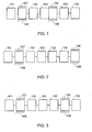
- Fig. 1 is a schematic diagram showing a configuration of the present invention.
- the present invention is essentially comprised of:
- the energy release control clutch device 104 may be provided in any of the following methods as applicable:
- the accumulation transmission 102 is provided with irreversible transmission or an irreversible transmission such as irreversible transmission worm and worm gear set is provided, the one-way transmission 107 otherwise disposed at where between the input end of the spring 103 and the static part 106 of the casing may be omitted.
- the accumulation transmission 102 may be comprised of one with its speed variable depending on the value of the torque so that when the accumulation level is lower of the spring 103, the accumulation transmission 102 winds up the spring 103 with smaller torque and faster speed from the input mechanism 101, and later winds up the spring 103 at greater torque and slower speed from the input mechanism 101 when the speed variable ratio changes as the accumulation of the spring 103 increases.
- Fig. 5 is a schematic diagram showing operation relation between accumulation value and deceleration ratio of the present invention.
- a relates to the accumulation value of the spring 103; and b, the deceleration ratio between the input rpm from the input mechanism 101 and the drive rpm at the input end of the spring 103.
- the transmission with its speed variable depending on the value of the torque may be of continuous variable transmission, or step variable transmission, the operation methods include manual or automatic speed variation ratio of the conventional speed variable device.
- the present invention of a spring device adapted as accumulator and energy release trigger by driving a spring device to gradually wind up from manually driven or other intermittent kinetics, and driving an energy release controller to trigger off the spring to release energy for driving a load once the accumulation in the spring reaches a preset value for effectively accumulate discontinuous kinetics, kinetics at lower rpm, or instable random kinetics to drive the energy release control when the accumulation reaches the preset value to trigger off the spring to release energy for providing higher power and rpm output is innovative with precise functions.
- the spring device adapted as intermittent energy accumulator and energy release trigger of present invention when applied may be further characterized in that an optional deceleration type of inputted energy storage transmission 102 is disposed to help inputting that even minimum kinetics are capable of driving the spring 103 to mount up for accumulation purpose; or an optional acceleration type of output transmission 102' is disposed to accelerate the rpm of the generator, or the pump, or the fan, or other mechanical load in the course of output operation; or an optional deceleration type of output transmission 102' is provided to generate output with larger torque and slower rpm to drive a load. Therefore, this patent application is duly filed.
Landscapes
- Engineering & Computer Science (AREA)
- Chemical & Material Sciences (AREA)
- Combustion & Propulsion (AREA)
- Mechanical Engineering (AREA)
- General Engineering & Computer Science (AREA)
- Connection Of Motors, Electrical Generators, Mechanical Devices, And The Like (AREA)
- One-Way And Automatic Clutches, And Combinations Of Different Clutches (AREA)
Abstract
Description
- The present invention is related to a spring device for accumulating random kinetics in the spring to release higher power output or to drive a load at higher rpm, and more particularly to a device that gradually restoring non-continuous kinetics, kinetics at lower rpm, or instable random kinetics through a transmission to accumulate kinetics by winding the spring, and to drive the release controller while the accumulator rises to a preset value to trigger the spring to release kinetics for driving a load until the release of the kinetics reaches a periodically balanced status with the load side.
- Conventional driving approach by manual cranking, pulling or winding such as a hand cranking or pedal generator; or a device driven by wind such as a micro wind generator or pump; or a device generating power by random kinetics; or a device generating power by vibration; or a device driven by a rotor or a motive block such as one produced by SEIKO in which the random kinetics from the rotor charges an electric storage device directly through a generator driven by an acceleration gear, with the electric energy supplied from the electric storage device to drive the dynamo-electric power system of the movement of a quartz wristwatch. However, such configurations were found with defectives including intermittent discontinuous random kinetics from the rotor or slow speed or weak kinetics from the rotor will slower the rpm of the generator driven even though acceleration gear is provided, which result in lower voltage output of the generator, even lower than the voltage of the electric storage device, and failure to fully charge the unsaturated rechargeable electric storage device. This state results in waste of the random kinetics from the rotor. In addition, when non-uniform speed drives to generate energy, the voltage generated from non-uniform speed at lower speed stage is lower than the voltage of the electric storage device, which also causes the failure of the electric storage device to fully charge and store energy and become waste of the kinetics.
- The primary purpose of the present invention is to provide a spring device that is adapted as an intermittent energy accumulator and an energy release trigger to reduce the waste of random kinetics. The spring gradually winds up by manual or other random intermittent kinetics for energy accumulation to a preset value to drive the energy release control device for the spring to release the energy to further drive a load.
-
-
Fig. 1 is the first schematic diagram showing a configuration of the present invention. -
Fig. 2 is the second schematic diagram showing another configuration of the present invention. -
Fig. 3 is the third schematic diagram showing another configuration of the present invention. -
Fig. 4 is the forth schematic diagram showing another configuration of the present invention. -
Fig. 5 is a schematic diagram showing operation relation between spring accumulation value and deceleration ratio of the present invention.- 101:
- input mechanism
- 102:
- energy accumulation transmission device
- 102':
- output transmission
- 103:
- spring
- 104:
- energy release control clutch device
- 105:
- load
- 106:
- static part of the casing
- 107:
- one-way transmission
- Conventional manual drive, or random discontinuous drive, or drive at low rpm, or drive with unstable random kinetics usually insufficient to drive a load effectively. Taking a manually driven generator for example, it generates pulse output voltage due to instable speed or the output voltage is insufficient at lower rpm since it is difficult for the manual drive to drive at uniform speed. Similar defect is found with a pedal generator. When randomly driven by an unbalanced rotor or motive block, the rpm also appears lower or instable; and similar defect occurs when the load is driven by wind or tidal energy. If driven by any of these forms of kinetics, the generated voltage from the generator often gets too low for meaningful use due to lower rpm or lower generated voltage at lower speed under the non-union motion and result in the waste of energy. For example, if the generator operates for charging purpose and its output voltage is lower than that of a rechargeable energy storage device (ESD), or when operates for driving an energy driven light emitting device (LED), and the output voltage is insufficient to reach that enables LED, i.e., to reach the level of working voltage of the LED; or when operates for driving a mechanical displacement device, and the force created by energy fails to overcome the static friction in the mechanism; energy is wasted in nothing since the weaker random kinetics input would become ineffective power.
- The spring device adapted as intermittent energy accumulator and energy release trigger of the present invention relates to one that is driven by a transmission to accumulate kinetics from those discontinuous, slower rpm or instable random kinetics, and is triggered off to release the accumulated kinetics through a release control device once the accumulation of the spring device mounts up to a preset output value to release greater power output or higher rpm in driving a load.
Fig. 1 is a schematic diagram showing a configuration of the present invention. The present invention is essentially comprised of: - ---an input mechanism 101: including a rolling shaft, a roller wheel, or a handle or any other that permits rotational drive, reciprocal pull, swing, or vibration subject to be driven by manual, mechanical, electromagnetic, electric motor force or random kinetics, or subject to one way or two-way drive by natural force to produce one-way displacement drive kinetics;
- ---an energy accumulation transmission device 102: is related to an optional item installed by requirement or not, which includes various types of devices of acceleration, deceleration, uniform speed, changing motion for circulation or linear transmission, e.g., a transmission gear set or gear system or linkages, for transmission of mechanical kinetics from the
input mechanism 101 to drive aspring 103 to be described below; - ---the output transmission 102': related to a rotational or linear transmission of acceleration, deceleration, equal speed, or variable motion forms, e.g., various types of transmission gear sets, or chain system or linkage for transmitting the mechanical drive kinetics inputted to the
spring 103 to further drive theload 105; theoutput transmission 102 is an optional item that may be or may not be provided depending on requirement; - ---the spring 103: a spring device to accumulate mechanic energy from the
input mechanism 101 includes vortex, spiral, sheet, or any other form of spring device that allows accumulation of mechanical energy; - ---an energy release control clutch device 104: comprised of a mechanical clutch with its torque limit actuation function that may be fixed, preset or adjustable, or of a friction clutch provided with a static friction value greater than a dynamic friction, or of a clutch with limited torque value controlled by electro-magnetic or fluid force;
- The energy release
control clutch device 104 may be provided in any of the following methods as applicable: - (1) One of both interaction ends of the energy release
control clutch device 104 is linked to the output end of thespring 103 and coupled to the input end of aload 105 through the output transmission 102' and the other is connected to astatic part 106 of the casing, when the elasticity from thespring 103 is subject to reaches its critical value, the energy releasecontrol clutch device 104 is released to output the energy accumulated by thespring 103 through the output transmission 102' to drive aload 105 and the energy releasecontrol clutch device 104 is closed again when thespring 103 stops outputting as illustrated inFig. 1 for a schematic diagram showing a configuration of the present invention; or - (2) Both interaction ends of the energy
release control clutch 104 device are connected between the motive part of theload 105 and thestatic part 106 of the casing; when the elastic force from thespring 103 is subject to reaches its critical value, the energy releasecontrol clutch device 104 is released to output the accumulated energy from thespring 103 to drive theload 105 and the energy releasecontrol clutch device 104 is closed again while thespring 103 stops outputting as illustrated inFig. 2 for a schematic diagram showing another configuration of the present invention; or, - (3) One end of both interaction ends of the energy release
control clutch device 104 is coupled to a coupling structure of the motive part of theload 105 and further to thespring 103 through the output transmission 102'; and the other end is disposed to thestatic part 106 of the casing; when the elastic force from thespring 103 is subject to reaches its critical value, the energy releasecontrol clutch device 104 is released to output the accumulated energy from thespring 103 to drive theload 105 and the energy releasecontrol clutch device 104 is closed again when thespring 103 stops outputting as illustrated inFig. 3 for a schematic diagram showing another configuration of the present invention; or, - (4) The
load 105 given with different value between static friction and dynamic friction functions as a damper; the input end of thespring 103 is coupled to the output end of theaccumulation transmission 102 to accumulate energy from theinput mechanism 101; the output end of thespring 103 drives theload 105; theload 105 has a greater static friction than the dynamic friction to provide similar function of energy releasecontrol clutch device 104, thus the energy releasecontrol clutch device 104 may not be used; when the accumulated torque at thespring 103 reaches the critical value of the static friction, theload 105 turns from static friction status to dynamic friction status for driving; thespring 103 release kinetics to drive theload 105 until the kinetics of thespring 103 is balanced with the dynamic friction value of the load to return the load to static friction status as illustrated inFig. 4 for a schematic diagram showing another configuration of the present invention.- ---the load 105: related to any rotational or linear load driven by the
spring 103, and more particularly, to one for directly driving a pump or driving a pump through an acceleration or deceleration output transmission 102' so to further pumping the working liquid, or driving a fan, or driving other mechanical load; by directly driving a generator, or driving a generator through the acceleration or deceleration output transmission 102'; the electric energy from the generator in turn directly outputs to drive a load, or charges a rechargeable device; and the electric energy from the rechargeable device is supplied to a wristwatch or a pocket watch to drive a quartz movement or any other movement driven by electric energy, or the electric energy is supplied to a load including a portable communication, video, information AV recorder/player, camera, camera/video recorder, or light emitting device;- --a one-way transmission 107: related to ratchet gear and ratchet wheel structure to engage in one-way drive, or any other one-way transmission; disposed at where between the input end of the
spring 103 and thestatic part 106 of the casing; the input end of thespring 103 relates to any rotational mechanical part disposed between theinput mechanism 101 through theaccumulation transmission 102 and the input end of thespring 103.
- --a one-way transmission 107: related to ratchet gear and ratchet wheel structure to engage in one-way drive, or any other one-way transmission; disposed at where between the input end of the
- ---the load 105: related to any rotational or linear load driven by the
- In the spring system adapted as intermittent energy accumulator and energy release trigger of the present invention, if the
accumulation transmission 102 is provided with irreversible transmission or an irreversible transmission such as irreversible transmission worm and worm gear set is provided, the one-way transmission 107 otherwise disposed at where between the input end of thespring 103 and thestatic part 106 of the casing may be omitted. - To increase the accumulation efficiency, the
accumulation transmission 102 may be comprised of one with its speed variable depending on the value of the torque so that when the accumulation level is lower of thespring 103, theaccumulation transmission 102 winds up thespring 103 with smaller torque and faster speed from theinput mechanism 101, and later winds up thespring 103 at greater torque and slower speed from theinput mechanism 101 when the speed variable ratio changes as the accumulation of thespring 103 increases. -
Fig. 5 is a schematic diagram showing operation relation between accumulation value and deceleration ratio of the present invention. Wherein, a relates to the accumulation value of thespring 103; and b, the deceleration ratio between the input rpm from theinput mechanism 101 and the drive rpm at the input end of thespring 103. The transmission with its speed variable depending on the value of the torque may be of continuous variable transmission, or step variable transmission, the operation methods include manual or automatic speed variation ratio of the conventional speed variable device. - The present invention of a spring device adapted as accumulator and energy release trigger by driving a spring device to gradually wind up from manually driven or other intermittent kinetics, and driving an energy release controller to trigger off the spring to release energy for driving a load once the accumulation in the spring reaches a preset value for effectively accumulate discontinuous kinetics, kinetics at lower rpm, or instable random kinetics to drive the energy release control when the accumulation reaches the preset value to trigger off the spring to release energy for providing higher power and rpm output is innovative with precise functions.
- In addition, the spring device adapted as intermittent energy accumulator and energy release trigger of present invention when applied may be further characterized in that an optional deceleration type of inputted
energy storage transmission 102 is disposed to help inputting that even minimum kinetics are capable of driving thespring 103 to mount up for accumulation purpose; or an optional acceleration type of output transmission 102' is disposed to accelerate the rpm of the generator, or the pump, or the fan, or other mechanical load in the course of output operation; or an optional deceleration type of output transmission 102' is provided to generate output with larger torque and slower rpm to drive a load. Therefore, this patent application is duly filed.
Claims (13)
- A spring device includes an intermittent accumulator and kinetics release trigger that gradually winds up to accumulate energy as driven by manual or other intermittent random kinetics and drives an kinetics release control to trigger off the spring to release kinetics to drive a load once the kinetics of the spring is accumulated to a preset value and is essentially comprised of:---an input mechanism 101: including a rolling shaft, a roller wheel, or a handle or any other that permits rotational drive, reciprocal pull, swing, or vibration subject to be driven by manual, mechanical, electromagnetic, electric motor force or random kinetics, or subject to one way or two-way drive by natural force to produce one-way displacement drive kinetics;---an energy accumulation transmission device 102: is related to an optional item installed by requirement or not, which includes various types of devices of acceleration, deceleration, uniform speed, changing motion for circulation or linear transmission, e.g., a transmission gear set or gear system or linkages, for transmission of mechanical kinetics from the input mechanism 101 to drive a spring 103 to be described below;---the output transmission 102': related to a rotational or linear transmission of acceleration, deceleration, equal speed, or variable motion forms, e.g., various types of transmission gear sets, or chain system or linkage for transmitting the mechanical drive kinetics inputted to the spring 103 to further drive the load 105; the output transmission 102 is an optional item that may be or may not be provided depending on requirement;---the spring 103: a spring device to accumulate mechanic energy from the input mechanism 101 includes vortex, spiral, sheet, or any other form of spring device that allows accumulation of mechanical energy;---an energy release control clutch device 104: comprised of a mechanical clutch with its torque limit actuation function that may be fixed, preset or adjustable, or of a friction clutch provided with a static friction value greater than a dynamic friction, or of a clutch with limited torque value controlled by electro-magnetic or fluid force;further, the energy release control clutch device 104 comprises a motive part as a functional structure for storing and releasing energy and a static part as a structure for interacting with the structure of motive part; a casing can be optionally provided for the static part to jointly constitute the static part 106 of the casing to facilitate fixation;---the load 105: related to any rotational or linear load driven by the spring 103, and more particularly, to one for directly driving a pump or driving a pump through an acceleration or deceleration output transmission 102' so to further pumping the working liquid, or driving a fan, or driving other mechanical load; by directly driving a generator, or driving a generator through the acceleration or deceleration output transmission 102'; the electric energy from the generator in turn directly outputs to drive a load, or charges a rechargeable device; and the electric energy from the rechargeable device is supplied to a wristwatch or a pocket watch to drive a quartz movement or any other movement driven by electric energy, or the electric energy is supplied to a load including a portable communication, video, information AV recorder/player, camera, camera/video recorder, or light emitting device;---a one-way transmission 107: related to ratchet gear and ratchet wheel structure to engage in one-way drive, or any other one-way transmission; disposed at where between the input end of the spring 103 and the static part 106 of the casing; the input end of the spring 103 relates to any circulating mechanical part disposed between the input mechanism 101 through the accumulation transmission 102 and the input end of the end of the spring 103; the one-way transmission 107 is an optional item that may be or may not be provided depending on requirement.
- A spring device includes an intermittent energy accumulator and kinetics release trigger of Claim 1, wherein the energy release control clutch device 104 could be installed in following approach: one of both interaction ends of the energy release control clutch device 104 is linked to the output end of the spring 103 and coupled to the input end of a load 105 through the output transmission 102' and the other is connected to a static part 106 of the casing, when the elastic force from the spring 103 is subject to reaches its critical value, the energy release control clutch device 104 is released through the output transmission 102' to output the energy accumulated by the spring 103 to drive a load 105 and the energy release control clutch device 104 is closed again when the spring 103 stops outputting.
- A spring device includes an intermittent energy accumulator and kinetics release trigger of Claim 1, wherein the energy release control clutch device 104 could be installed in following approach: both interaction ends of the energy release control clutch device 104 are disposed at where between the load 105 and the static part 106 of the casing; when the elastic force from the spring 103 is subject to reaches its critical value, the energy release control clutch device 104 is released to output the accumulated energy for the spring 103 to drive the load 105 and the energy release control clutch device 104 is closed again when the spring 103 stops outputting.
- A spring device includes an intermittent energy accumulator and kinetics release trigger of Claim 1, wherein the energy release control clutch device 104 could be installed in following approach: one end of both interaction ends of the clutch 104 is coupled to a coupling structure of the motive part of the load 105 and further to the spring 103 through the output transmission 102' and the other end is disposed to the static part 106 of the casing; when the elastic force from the spring 103 is subject to reaches its critical value, the energy release control clutch device 104 is released to output the accumulated energy from the spring 103 to drive the load 105 and the clutch 104 is closed again when the spring 103 stops outputting.
- A spring device includes an intermittent energy accumulator and kinetics release trigger of Claim 1, wherein the energy release control clutch device 104 could be installed in following approach: the load 105 given with different value between static friction and dynamic friction functions as a damper; the input end of the spring 103 is coupled to the output end of the accumulation transmission 102 to accumulate energy from the input mechanism 101; the output end of the spring 103 drives the load 105; the load 105 has a greater static friction than the dynamic friction to provide similar function of energy release control clutch device 104, thus the energy release control clutch 104 may not be used; when the accumulated torque at the spring 103 reaches the critical value of the static friction, the load 105 turns from static friction status to dynamic friction status for driving; the spring 103 release kinetics to drive the load 105 until the kinetics of the spring 103 is balanced with the mobile friction value of the load to return the load to static friction status.
- A spring device includes an intermittent energy accumulator and kinetics release trigger of Claim 1, wherein in the spring device adapted with intermittent accumulator and energy release trigger of the present invention, if the accumulation transmission 102 is provided with irreversible transmission or an irreversible transmission such as an irreversible transmission worm and worm gear set is provided, the one-way transmission 107 otherwise disposed between the input end of the spring 103 and the static part 106 of the casing may be omitted.
- A spring device includes an intermittent energy accumulator and kinetics release trigger of Claim 1, wherein the accumulation transmission 102 may be comprised of one with its speed variable depending on the value of the torque so that when the accumulation level is lower of the spring 103, the accumulation transmission 102 winds up the spring 103 with smaller torque and faster speed from the input mechanism 101, and later winds up the spring 103 at greater torque and slower speed from the input mechanism 101 when the speed variable ratio changes as the accumulation of the spring 103 increases.
- A spring device includes an intermittent energy accumulator and kinetics release trigger of Claim 1, wherein an optional deceleration type of inputted energy storage transmission 102 is disposed to assist inputting that even minute kinetics are capable of driving the spring 103 to mount up for accumulation purpose.
- A spring device includes an intermittent energy accumulator and kinetics release trigger of Claim 1, wherein an optional acceleration type of output transmission 102' is disposed to accelerate the rpm of the generator, or the pump, or the fan, or other load in the course of output operation.
- A spring device includes an intermittent energy accumulator and kinetics release trigger of Claim 1, wherein an optional deceleration type of output transmission 102' is provided to generate output with larger torque and slower rpm to drive a load.
- A spring device includes an intermittent energy accumulator and kinetics release trigger of Claim 1, wherein an optional deceleration type of inputted energy storage transmission 102 and an optional acceleration type of output transmission 102' are provided with characteristics of assisting inputting that even minute kinetics are capable of driving the spring 103 to mount up for accumulation purpose and accelerating the rpm of the generator, or the pump, or the fan, or other load in the course of output operation respectively.
- A spring device includes an intermittent energy accumulator and kinetics release trigger of Claim 1, wherein an optional deceleration type of inputted energy storage transmission 102 and an optional acceleration type of output transmission 102' are provided with characteristics of assisting inputting that even minute kinetics are capable of driving the spring 103 to mount up for accumulation purpose and generating output with larger torque and slower rpm to drive a load respectively.
- A spring device having an intermittent accumulator and a kinetic energy release trigger that gradually winds up to accumulate energy when driven by manual or other random intermittent kinetic energy, and drives a kinetic energy release control to trigger the spring to release kinetic energy to drive a load once the kinetic energy in the spring accumulates to a preset value.
Priority Applications (7)
| Application Number | Priority Date | Filing Date | Title |
|---|---|---|---|
| US11/500,976 US7708123B2 (en) | 2006-08-09 | 2006-08-09 | Spring device with capability of intermittent random energy accumulator and kinetics release trigger |
| TW096132829A TW200912135A (en) | 2006-08-09 | 2007-09-03 | Spring device with capability of intermittent random energy accumulator and kinetics release trigger |
| ES07253766.5T ES2606704T3 (en) | 2007-09-24 | 2007-09-24 | Spring device with intermittent random energy storage capacity and kinetic release trigger |
| EP07253766.5A EP2039930B1 (en) | 2006-08-09 | 2007-09-24 | Spring device with capability of intermittent random energy accumulator and kinetics release trigger |
| CN2007101627392A CN101408152B (en) | 2006-08-09 | 2007-10-08 | Spring device capable of intermittent energy storage and firing energy release |
| KR1020070119628A KR20090053018A (en) | 2006-08-09 | 2007-11-22 | Spring device that accumulates energy intermittently and releases energy by trigger |
| JP2007319341A JP5660749B2 (en) | 2006-08-09 | 2007-12-11 | Spring device |
Applications Claiming Priority (6)
| Application Number | Priority Date | Filing Date | Title |
|---|---|---|---|
| US11/500,976 US7708123B2 (en) | 2006-08-09 | 2006-08-09 | Spring device with capability of intermittent random energy accumulator and kinetics release trigger |
| TW096132829A TW200912135A (en) | 2006-08-09 | 2007-09-03 | Spring device with capability of intermittent random energy accumulator and kinetics release trigger |
| EP07253766.5A EP2039930B1 (en) | 2006-08-09 | 2007-09-24 | Spring device with capability of intermittent random energy accumulator and kinetics release trigger |
| CN2007101627392A CN101408152B (en) | 2006-08-09 | 2007-10-08 | Spring device capable of intermittent energy storage and firing energy release |
| KR1020070119628A KR20090053018A (en) | 2006-08-09 | 2007-11-22 | Spring device that accumulates energy intermittently and releases energy by trigger |
| JP2007319341A JP5660749B2 (en) | 2006-08-09 | 2007-12-11 | Spring device |
Publications (2)
| Publication Number | Publication Date |
|---|---|
| EP2039930A1 true EP2039930A1 (en) | 2009-03-25 |
| EP2039930B1 EP2039930B1 (en) | 2016-11-09 |
Family
ID=50443121
Family Applications (1)
| Application Number | Title | Priority Date | Filing Date |
|---|---|---|---|
| EP07253766.5A Not-in-force EP2039930B1 (en) | 2006-08-09 | 2007-09-24 | Spring device with capability of intermittent random energy accumulator and kinetics release trigger |
Country Status (6)
| Country | Link |
|---|---|
| US (1) | US7708123B2 (en) |
| EP (1) | EP2039930B1 (en) |
| JP (1) | JP5660749B2 (en) |
| KR (1) | KR20090053018A (en) |
| CN (1) | CN101408152B (en) |
| TW (1) | TW200912135A (en) |
Cited By (2)
| Publication number | Priority date | Publication date | Assignee | Title |
|---|---|---|---|---|
| EP2672143A3 (en) * | 2012-06-08 | 2014-09-17 | Chuy-Nan Chio | Energy storing device in which energy is stored through spring torsion |
| WO2018157934A1 (en) * | 2017-03-02 | 2018-09-07 | Beiersdorf Ag | Device and method for monitoring suspensions |
Families Citing this family (11)
| Publication number | Priority date | Publication date | Assignee | Title |
|---|---|---|---|---|
| ATE509375T1 (en) * | 2009-06-10 | 2011-05-15 | Mikko Kalervo Vaeaenaenen | HIGH PERFORMANCE SOLAR CELL |
| US8324998B2 (en) * | 2009-09-16 | 2012-12-04 | Ecoharvester, Inc. | Wireless switch with multipolar electromagnetic generator |
| US9048717B2 (en) * | 2009-09-16 | 2015-06-02 | Ecoharvester, Inc. | Multipolar electromagnetic generator |
| WO2015006612A1 (en) * | 2013-07-10 | 2015-01-15 | Worcester Polytechnic Institute | Actuation systems and methods |
| CN103711664A (en) * | 2013-12-13 | 2014-04-09 | 广西科技大学 | Potential energy storage type device for collecting scattered energy |
| CN104653407A (en) * | 2015-01-28 | 2015-05-27 | 胡伏平 | Device for converting mechanical energy into electrical energy |
| CN106763607B (en) * | 2016-12-21 | 2019-08-13 | 梁渤涛 | A mechanism that stores and releases mechanical energy |
| AU2020340604B2 (en) | 2019-09-03 | 2025-10-16 | Trudell Medical International Inc. | Medical device with energy harvesting system |
| CN110671286B (en) * | 2019-10-15 | 2020-12-25 | 河南理工大学 | Linear vibration energy storage device |
| CN112537711A (en) * | 2020-11-27 | 2021-03-23 | 镇江领驭立方智能装备有限公司 | Rail type transportation device applied to wind power station |
| CN117287358A (en) * | 2023-09-21 | 2023-12-26 | 长沙丰泰电子科技有限公司 | A production line elastic component energy storage system and its working method |
Citations (4)
| Publication number | Priority date | Publication date | Assignee | Title |
|---|---|---|---|---|
| US3812933A (en) * | 1970-04-21 | 1974-05-28 | Helmut Darda | Energy storing drive means |
| WO2001042648A1 (en) | 1999-12-10 | 2001-06-14 | Barreiro Motor Company Pty Ltd | Spring motor for generating electrical energy |
| WO2004015790A1 (en) | 2002-08-09 | 2004-02-19 | Mecel Aktiebolag | Method and device for transforming vibration energy |
| FR2872868A1 (en) | 2004-07-06 | 2006-01-13 | Commissariat Energie Atomique | ENERGY RECOVERY DEVICE |
Family Cites Families (22)
| Publication number | Priority date | Publication date | Assignee | Title |
|---|---|---|---|---|
| JPS5861333A (en) * | 1981-10-02 | 1983-04-12 | Ogura Clutch Co Ltd | Solenoid spring clutch |
| US4570768A (en) * | 1984-09-21 | 1986-02-18 | Mita Industrial Co., Ltd. | Electromagnetically controlled spring clutch mechanism |
| JPH06103048B2 (en) * | 1987-01-28 | 1994-12-14 | 天竜丸澤株式会社 | Electromagnetic spring clutch |
| US5135086A (en) * | 1990-08-17 | 1992-08-04 | Star Precision Tools, Inc. | Assembly tool with rapid release electromagnetic clutch |
| US5573472A (en) * | 1993-06-07 | 1996-11-12 | Ciolli; Donald A. | Wrap spring downshift mechanism |
| CN2237734Y (en) * | 1994-04-18 | 1996-10-16 | 姚铁人 | Spring power unit |
| JPH0942410A (en) * | 1995-08-01 | 1997-02-14 | Keiichi Akashi | Transmission |
| EP0961046B1 (en) * | 1998-05-26 | 2002-08-14 | Siemens Building Technologies AG | Driving device for a positioning element |
| GB2353071B (en) * | 1999-06-23 | 2003-10-01 | Mannesmann Sachs Ag | Friction clutch and pressure plate module therefor |
| GB2380531B (en) * | 2000-02-15 | 2004-10-20 | Luk Lamellen & Kupplungsbau | Torque transfer device. |
| CN2420437Y (en) * | 2000-03-18 | 2001-02-21 | 力嘉玩具有限公司 | Push spring power gearbox |
| CN2414215Y (en) * | 2000-04-18 | 2001-01-10 | 李继承 | Lever kinetic energy electricity generator |
| US6755284B2 (en) * | 2001-05-24 | 2004-06-29 | Ventra Group Inc. | Electrically driven parking brake actuation assembly |
| US6817453B2 (en) * | 2001-06-25 | 2004-11-16 | Inventio Ag | Remote brake release with clutch |
| JP2006057802A (en) * | 2004-08-23 | 2006-03-02 | Ntn Corp | Reverse input cut-off device |
| US7182194B2 (en) * | 2004-09-01 | 2007-02-27 | Magna Powertrain Usa, Inc. | Low power modulating clutch control system with combination accumulator and piston actuator |
| JP4262659B2 (en) * | 2004-09-27 | 2009-05-13 | 株式会社クボタ | Engine recoil starter |
| JP2006283855A (en) * | 2005-03-31 | 2006-10-19 | Toyoda Gosei Co Ltd | Drive device |
| JP2006326766A (en) * | 2005-05-26 | 2006-12-07 | Matsushita Electric Works Ltd | Rotating tool |
| US7798941B2 (en) * | 2005-06-30 | 2010-09-21 | Gm Global Technology Operations, Inc. | Compliance-on-demand for vehicle transmission clutch |
| JP4576300B2 (en) * | 2005-07-08 | 2010-11-04 | モリテックスチール株式会社 | Spring drive mechanism |
| US20070137978A1 (en) * | 2005-12-16 | 2007-06-21 | Aisin Seiki Kabushiki Kaisha | Seat adjusting apparatus for vehicle |
-
2006
- 2006-08-09 US US11/500,976 patent/US7708123B2/en not_active Expired - Fee Related
-
2007
- 2007-09-03 TW TW096132829A patent/TW200912135A/en unknown
- 2007-09-24 EP EP07253766.5A patent/EP2039930B1/en not_active Not-in-force
- 2007-10-08 CN CN2007101627392A patent/CN101408152B/en not_active Expired - Fee Related
- 2007-11-22 KR KR1020070119628A patent/KR20090053018A/en not_active Ceased
- 2007-12-11 JP JP2007319341A patent/JP5660749B2/en not_active Expired - Fee Related
Patent Citations (4)
| Publication number | Priority date | Publication date | Assignee | Title |
|---|---|---|---|---|
| US3812933A (en) * | 1970-04-21 | 1974-05-28 | Helmut Darda | Energy storing drive means |
| WO2001042648A1 (en) | 1999-12-10 | 2001-06-14 | Barreiro Motor Company Pty Ltd | Spring motor for generating electrical energy |
| WO2004015790A1 (en) | 2002-08-09 | 2004-02-19 | Mecel Aktiebolag | Method and device for transforming vibration energy |
| FR2872868A1 (en) | 2004-07-06 | 2006-01-13 | Commissariat Energie Atomique | ENERGY RECOVERY DEVICE |
Cited By (2)
| Publication number | Priority date | Publication date | Assignee | Title |
|---|---|---|---|---|
| EP2672143A3 (en) * | 2012-06-08 | 2014-09-17 | Chuy-Nan Chio | Energy storing device in which energy is stored through spring torsion |
| WO2018157934A1 (en) * | 2017-03-02 | 2018-09-07 | Beiersdorf Ag | Device and method for monitoring suspensions |
Also Published As
| Publication number | Publication date |
|---|---|
| US20080036127A1 (en) | 2008-02-14 |
| CN101408152B (en) | 2012-12-12 |
| KR20090053018A (en) | 2009-05-27 |
| JP5660749B2 (en) | 2015-01-28 |
| TW200912135A (en) | 2009-03-16 |
| JP2009144732A (en) | 2009-07-02 |
| EP2039930B1 (en) | 2016-11-09 |
| CN101408152A (en) | 2009-04-15 |
| US7708123B2 (en) | 2010-05-04 |
Similar Documents
| Publication | Publication Date | Title |
|---|---|---|
| EP2039930B1 (en) | Spring device with capability of intermittent random energy accumulator and kinetics release trigger | |
| US10012276B2 (en) | System and method for electrically controllable transmissions | |
| US8866314B2 (en) | Method for operating a power rotary actuator and a power plant for carrying out said method | |
| CN103711664A (en) | Potential energy storage type device for collecting scattered energy | |
| JP6144484B2 (en) | Door closer | |
| FR2919442B1 (en) | INERTIA WHEEL WITH PROGRESSIVE LAUNCH. | |
| Li et al. | A high-performance vibration energy modulator with automatic energy accumulation-discharge strategy for low frequency energy harvesting | |
| EP0692155B1 (en) | Synchronous motor system employing a non-synchronous motor for enhanced torque output | |
| Wu et al. | A switchable clutched parallel elasticity actuator | |
| JP2002235640A (en) | Engine starter | |
| JP5758952B2 (en) | Spring device | |
| CN101292085A (en) | small engine starter | |
| GB2479157A (en) | Door closer with electricity generator | |
| KR101513396B1 (en) | Spring device with capability of intermittent random energy accumulator and kinetics release trigger | |
| TW201600720A (en) | Spring device with capability of intermittent random energy accumulator and kinetics release trigger | |
| KR101495477B1 (en) | Spring device with capability of intermittent random energy accumulator and kinetics release trigger | |
| CN203670120U (en) | Potential energy storage type scattered energy gathering device | |
| RU2153099C1 (en) | Energy-producing inertial mechanical spring unit | |
| KR20110115285A (en) | Output enhancer | |
| CN205315211U (en) | Electric energy controlling means is changeed to clockwork spring mechanical energy | |
| KR970075587A (en) | Multifunctional Combined Power System | |
| RU2516883C1 (en) | Flywheel of alternate moment of inertia | |
| RU2523363C1 (en) | Mechanical energy accumulator | |
| CN2714888Y (en) | Ratchet one-way starter clutch | |
| CN212080064U (en) | A high-vibration low-power DC micromotor |
Legal Events
| Date | Code | Title | Description |
|---|---|---|---|
| PUAI | Public reference made under article 153(3) epc to a published international application that has entered the european phase |
Free format text: ORIGINAL CODE: 0009012 |
|
| AK | Designated contracting states |
Kind code of ref document: A1 Designated state(s): AT BE BG CH CY CZ DE DK EE ES FI FR GB GR HU IE IS IT LI LT LU LV MC MT NL PL PT RO SE SI SK TR |
|
| AX | Request for extension of the european patent |
Extension state: AL BA HR MK RS |
|
| 17P | Request for examination filed |
Effective date: 20090924 |
|
| 17Q | First examination report despatched |
Effective date: 20091022 |
|
| AKX | Designation fees paid |
Designated state(s): AT BE BG CH CY CZ DE DK EE ES FI FR GB GR HU IE IS IT LI LT LU LV MC MT NL PL PT RO SE SI SK TR |
|
| GRAP | Despatch of communication of intention to grant a patent |
Free format text: ORIGINAL CODE: EPIDOSNIGR1 |
|
| INTG | Intention to grant announced |
Effective date: 20160623 |
|
| GRAS | Grant fee paid |
Free format text: ORIGINAL CODE: EPIDOSNIGR3 |
|
| GRAA | (expected) grant |
Free format text: ORIGINAL CODE: 0009210 |
|
| AK | Designated contracting states |
Kind code of ref document: B1 Designated state(s): AT BE BG CH CY CZ DE DK EE ES FI FR GB GR HU IE IS IT LI LT LU LV MC MT NL PL PT RO SE SI SK TR |
|
| REG | Reference to a national code |
Ref country code: GB Ref legal event code: FG4D |
|
| REG | Reference to a national code |
Ref country code: AT Ref legal event code: REF Ref document number: 844178 Country of ref document: AT Kind code of ref document: T Effective date: 20161115 Ref country code: CH Ref legal event code: EP |
|
| REG | Reference to a national code |
Ref country code: IE Ref legal event code: FG4D |
|
| REG | Reference to a national code |
Ref country code: DE Ref legal event code: R096 Ref document number: 602007048631 Country of ref document: DE |
|
| REG | Reference to a national code |
Ref country code: NL Ref legal event code: FP |
|
| REG | Reference to a national code |
Ref country code: SE Ref legal event code: TRGR |
|
| PG25 | Lapsed in a contracting state [announced via postgrant information from national office to epo] |
Ref country code: LV Free format text: LAPSE BECAUSE OF FAILURE TO SUBMIT A TRANSLATION OF THE DESCRIPTION OR TO PAY THE FEE WITHIN THE PRESCRIBED TIME-LIMIT Effective date: 20161109 |
|
| REG | Reference to a national code |
Ref country code: LT Ref legal event code: MG4D |
|
| REG | Reference to a national code |
Ref country code: AT Ref legal event code: MK05 Ref document number: 844178 Country of ref document: AT Kind code of ref document: T Effective date: 20161109 |
|
| PG25 | Lapsed in a contracting state [announced via postgrant information from national office to epo] |
Ref country code: LT Free format text: LAPSE BECAUSE OF FAILURE TO SUBMIT A TRANSLATION OF THE DESCRIPTION OR TO PAY THE FEE WITHIN THE PRESCRIBED TIME-LIMIT Effective date: 20161109 Ref country code: GR Free format text: LAPSE BECAUSE OF FAILURE TO SUBMIT A TRANSLATION OF THE DESCRIPTION OR TO PAY THE FEE WITHIN THE PRESCRIBED TIME-LIMIT Effective date: 20170210 |
|
| PG25 | Lapsed in a contracting state [announced via postgrant information from national office to epo] |
Ref country code: FI Free format text: LAPSE BECAUSE OF FAILURE TO SUBMIT A TRANSLATION OF THE DESCRIPTION OR TO PAY THE FEE WITHIN THE PRESCRIBED TIME-LIMIT Effective date: 20161109 Ref country code: PL Free format text: LAPSE BECAUSE OF FAILURE TO SUBMIT A TRANSLATION OF THE DESCRIPTION OR TO PAY THE FEE WITHIN THE PRESCRIBED TIME-LIMIT Effective date: 20161109 Ref country code: AT Free format text: LAPSE BECAUSE OF FAILURE TO SUBMIT A TRANSLATION OF THE DESCRIPTION OR TO PAY THE FEE WITHIN THE PRESCRIBED TIME-LIMIT Effective date: 20161109 Ref country code: PT Free format text: LAPSE BECAUSE OF FAILURE TO SUBMIT A TRANSLATION OF THE DESCRIPTION OR TO PAY THE FEE WITHIN THE PRESCRIBED TIME-LIMIT Effective date: 20170309 Ref country code: IS Free format text: LAPSE BECAUSE OF FAILURE TO SUBMIT A TRANSLATION OF THE DESCRIPTION OR TO PAY THE FEE WITHIN THE PRESCRIBED TIME-LIMIT Effective date: 20170309 |
|
| PG25 | Lapsed in a contracting state [announced via postgrant information from national office to epo] |
Ref country code: EE Free format text: LAPSE BECAUSE OF FAILURE TO SUBMIT A TRANSLATION OF THE DESCRIPTION OR TO PAY THE FEE WITHIN THE PRESCRIBED TIME-LIMIT Effective date: 20161109 Ref country code: DK Free format text: LAPSE BECAUSE OF FAILURE TO SUBMIT A TRANSLATION OF THE DESCRIPTION OR TO PAY THE FEE WITHIN THE PRESCRIBED TIME-LIMIT Effective date: 20161109 Ref country code: CZ Free format text: LAPSE BECAUSE OF FAILURE TO SUBMIT A TRANSLATION OF THE DESCRIPTION OR TO PAY THE FEE WITHIN THE PRESCRIBED TIME-LIMIT Effective date: 20161109 Ref country code: SK Free format text: LAPSE BECAUSE OF FAILURE TO SUBMIT A TRANSLATION OF THE DESCRIPTION OR TO PAY THE FEE WITHIN THE PRESCRIBED TIME-LIMIT Effective date: 20161109 Ref country code: RO Free format text: LAPSE BECAUSE OF FAILURE TO SUBMIT A TRANSLATION OF THE DESCRIPTION OR TO PAY THE FEE WITHIN THE PRESCRIBED TIME-LIMIT Effective date: 20161109 |
|
| REG | Reference to a national code |
Ref country code: DE Ref legal event code: R097 Ref document number: 602007048631 Country of ref document: DE |
|
| PG25 | Lapsed in a contracting state [announced via postgrant information from national office to epo] |
Ref country code: BE Free format text: LAPSE BECAUSE OF FAILURE TO SUBMIT A TRANSLATION OF THE DESCRIPTION OR TO PAY THE FEE WITHIN THE PRESCRIBED TIME-LIMIT Effective date: 20161109 Ref country code: BG Free format text: LAPSE BECAUSE OF FAILURE TO SUBMIT A TRANSLATION OF THE DESCRIPTION OR TO PAY THE FEE WITHIN THE PRESCRIBED TIME-LIMIT Effective date: 20170209 |
|
| PLBE | No opposition filed within time limit |
Free format text: ORIGINAL CODE: 0009261 |
|
| STAA | Information on the status of an ep patent application or granted ep patent |
Free format text: STATUS: NO OPPOSITION FILED WITHIN TIME LIMIT |
|
| 26N | No opposition filed |
Effective date: 20170810 |
|
| PG25 | Lapsed in a contracting state [announced via postgrant information from national office to epo] |
Ref country code: SI Free format text: LAPSE BECAUSE OF FAILURE TO SUBMIT A TRANSLATION OF THE DESCRIPTION OR TO PAY THE FEE WITHIN THE PRESCRIBED TIME-LIMIT Effective date: 20161109 |
|
| REG | Reference to a national code |
Ref country code: DE Ref legal event code: R119 Ref document number: 602007048631 Country of ref document: DE |
|
| REG | Reference to a national code |
Ref country code: CH Ref legal event code: PL |
|
| REG | Reference to a national code |
Ref country code: SE Ref legal event code: EUG |
|
| REG | Reference to a national code |
Ref country code: NL Ref legal event code: MM Effective date: 20171001 |
|
| GBPC | Gb: european patent ceased through non-payment of renewal fee |
Effective date: 20170924 |
|
| PG25 | Lapsed in a contracting state [announced via postgrant information from national office to epo] |
Ref country code: MC Free format text: LAPSE BECAUSE OF FAILURE TO SUBMIT A TRANSLATION OF THE DESCRIPTION OR TO PAY THE FEE WITHIN THE PRESCRIBED TIME-LIMIT Effective date: 20161109 |
|
| REG | Reference to a national code |
Ref country code: IE Ref legal event code: MM4A |
|
| PG25 | Lapsed in a contracting state [announced via postgrant information from national office to epo] |
Ref country code: NL Free format text: LAPSE BECAUSE OF NON-PAYMENT OF DUE FEES Effective date: 20171001 Ref country code: LU Free format text: LAPSE BECAUSE OF NON-PAYMENT OF DUE FEES Effective date: 20170924 |
|
| REG | Reference to a national code |
Ref country code: FR Ref legal event code: ST Effective date: 20180531 |
|
| PG25 | Lapsed in a contracting state [announced via postgrant information from national office to epo] |
Ref country code: LI Free format text: LAPSE BECAUSE OF NON-PAYMENT OF DUE FEES Effective date: 20170930 Ref country code: IE Free format text: LAPSE BECAUSE OF NON-PAYMENT OF DUE FEES Effective date: 20170924 Ref country code: GB Free format text: LAPSE BECAUSE OF NON-PAYMENT OF DUE FEES Effective date: 20170924 Ref country code: DE Free format text: LAPSE BECAUSE OF NON-PAYMENT OF DUE FEES Effective date: 20180404 Ref country code: CH Free format text: LAPSE BECAUSE OF NON-PAYMENT OF DUE FEES Effective date: 20170930 |
|
| PG25 | Lapsed in a contracting state [announced via postgrant information from national office to epo] |
Ref country code: FR Free format text: LAPSE BECAUSE OF NON-PAYMENT OF DUE FEES Effective date: 20171002 Ref country code: IT Free format text: LAPSE BECAUSE OF NON-PAYMENT OF DUE FEES Effective date: 20170924 |
|
| PG25 | Lapsed in a contracting state [announced via postgrant information from national office to epo] |
Ref country code: MT Free format text: LAPSE BECAUSE OF NON-PAYMENT OF DUE FEES Effective date: 20170924 |
|
| REG | Reference to a national code |
Ref country code: ES Ref legal event code: FD2A Effective date: 20181018 |
|
| PG25 | Lapsed in a contracting state [announced via postgrant information from national office to epo] |
Ref country code: ES Free format text: LAPSE BECAUSE OF NON-PAYMENT OF DUE FEES Effective date: 20170925 |
|
| PG25 | Lapsed in a contracting state [announced via postgrant information from national office to epo] |
Ref country code: HU Free format text: LAPSE BECAUSE OF FAILURE TO SUBMIT A TRANSLATION OF THE DESCRIPTION OR TO PAY THE FEE WITHIN THE PRESCRIBED TIME-LIMIT; INVALID AB INITIO Effective date: 20070924 |
|
| PG25 | Lapsed in a contracting state [announced via postgrant information from national office to epo] |
Ref country code: SE Free format text: LAPSE BECAUSE OF NON-PAYMENT OF DUE FEES Effective date: 20170925 |
|
| PG25 | Lapsed in a contracting state [announced via postgrant information from national office to epo] |
Ref country code: CY Free format text: LAPSE BECAUSE OF NON-PAYMENT OF DUE FEES Effective date: 20161109 |
|
| PG25 | Lapsed in a contracting state [announced via postgrant information from national office to epo] |
Ref country code: TR Free format text: LAPSE BECAUSE OF FAILURE TO SUBMIT A TRANSLATION OF THE DESCRIPTION OR TO PAY THE FEE WITHIN THE PRESCRIBED TIME-LIMIT Effective date: 20161109 |