EP2039653A2 - Reactor for polycrystalline silicon and polycrystalline silicon production method - Google Patents
Reactor for polycrystalline silicon and polycrystalline silicon production method Download PDFInfo
- Publication number
- EP2039653A2 EP2039653A2 EP20080164540 EP08164540A EP2039653A2 EP 2039653 A2 EP2039653 A2 EP 2039653A2 EP 20080164540 EP20080164540 EP 20080164540 EP 08164540 A EP08164540 A EP 08164540A EP 2039653 A2 EP2039653 A2 EP 2039653A2
- Authority
- EP
- European Patent Office
- Prior art keywords
- raw material
- material gas
- gas supply
- reactor
- polycrystalline silicon
- Prior art date
- Legal status (The legal status is an assumption and is not a legal conclusion. Google has not performed a legal analysis and makes no representation as to the accuracy of the status listed.)
- Granted
Links
Images


Classifications
-
- C—CHEMISTRY; METALLURGY
- C30—CRYSTAL GROWTH
- C30B—SINGLE-CRYSTAL GROWTH; UNIDIRECTIONAL SOLIDIFICATION OF EUTECTIC MATERIAL OR UNIDIRECTIONAL DEMIXING OF EUTECTOID MATERIAL; REFINING BY ZONE-MELTING OF MATERIAL; PRODUCTION OF A HOMOGENEOUS POLYCRYSTALLINE MATERIAL WITH DEFINED STRUCTURE; SINGLE CRYSTALS OR HOMOGENEOUS POLYCRYSTALLINE MATERIAL WITH DEFINED STRUCTURE; AFTER-TREATMENT OF SINGLE CRYSTALS OR A HOMOGENEOUS POLYCRYSTALLINE MATERIAL WITH DEFINED STRUCTURE; APPARATUS THEREFOR
- C30B28/00—Production of homogeneous polycrystalline material with defined structure
- C30B28/12—Production of homogeneous polycrystalline material with defined structure directly from the gas state
-
- B—PERFORMING OPERATIONS; TRANSPORTING
- B01—PHYSICAL OR CHEMICAL PROCESSES OR APPARATUS IN GENERAL
- B01J—CHEMICAL OR PHYSICAL PROCESSES, e.g. CATALYSIS OR COLLOID CHEMISTRY; THEIR RELEVANT APPARATUS
- B01J19/00—Chemical, physical or physico-chemical processes in general; Their relevant apparatus
- B01J19/26—Nozzle-type reactors, i.e. the distribution of the initial reactants within the reactor is effected by their introduction or injection through nozzles
-
- C—CHEMISTRY; METALLURGY
- C01—INORGANIC CHEMISTRY
- C01B—NON-METALLIC ELEMENTS; COMPOUNDS THEREOF; METALLOIDS OR COMPOUNDS THEREOF NOT COVERED BY SUBCLASS C01C
- C01B33/00—Silicon; Compounds thereof
- C01B33/02—Silicon
- C01B33/021—Preparation
- C01B33/027—Preparation by decomposition or reduction of gaseous or vaporised silicon compounds other than silica or silica-containing material
- C01B33/035—Preparation by decomposition or reduction of gaseous or vaporised silicon compounds other than silica or silica-containing material by decomposition or reduction of gaseous or vaporised silicon compounds in the presence of heated filaments of silicon, carbon or a refractory metal, e.g. tantalum or tungsten, or in the presence of heated silicon rods on which the formed silicon is deposited, a silicon rod being obtained, e.g. Siemens process
-
- B—PERFORMING OPERATIONS; TRANSPORTING
- B01—PHYSICAL OR CHEMICAL PROCESSES OR APPARATUS IN GENERAL
- B01J—CHEMICAL OR PHYSICAL PROCESSES, e.g. CATALYSIS OR COLLOID CHEMISTRY; THEIR RELEVANT APPARATUS
- B01J2219/00—Chemical, physical or physico-chemical processes in general; Their relevant apparatus
- B01J2219/00049—Controlling or regulating processes
- B01J2219/00051—Controlling the temperature
- B01J2219/00132—Controlling the temperature using electric heating or cooling elements
- B01J2219/00135—Electric resistance heaters
-
- B—PERFORMING OPERATIONS; TRANSPORTING
- B01—PHYSICAL OR CHEMICAL PROCESSES OR APPARATUS IN GENERAL
- B01J—CHEMICAL OR PHYSICAL PROCESSES, e.g. CATALYSIS OR COLLOID CHEMISTRY; THEIR RELEVANT APPARATUS
- B01J2219/00—Chemical, physical or physico-chemical processes in general; Their relevant apparatus
- B01J2219/00049—Controlling or regulating processes
- B01J2219/00245—Avoiding undesirable reactions or side-effects
- B01J2219/00247—Fouling of the reactor or the process equipment
-
- Y—GENERAL TAGGING OF NEW TECHNOLOGICAL DEVELOPMENTS; GENERAL TAGGING OF CROSS-SECTIONAL TECHNOLOGIES SPANNING OVER SEVERAL SECTIONS OF THE IPC; TECHNICAL SUBJECTS COVERED BY FORMER USPC CROSS-REFERENCE ART COLLECTIONS [XRACs] AND DIGESTS
- Y10—TECHNICAL SUBJECTS COVERED BY FORMER USPC
- Y10T—TECHNICAL SUBJECTS COVERED BY FORMER US CLASSIFICATION
- Y10T117/00—Single-crystal, oriented-crystal, and epitaxy growth processes; non-coating apparatus therefor
- Y10T117/10—Apparatus
Definitions
- the present invention relates to a reactor for polycrystalline silicon used in producing polycrystalline silicon according to the Siemens method, and relates to a polycrystalline silicon production method.
- the Siemens method is known as a method for producing polycrystalline silicon of high purity used as a material of semiconductors.
- a raw material gas composed of chlorosilane and hydrogen is brought into contact with a heated silicon seed rod to deposit polycrystalline silicon on the surface through reactions of the raw material gas.
- a reactor for polycrystalline silicon in which many silicon seed rods are installed upright in a reactor is used as an apparatus for carrying out this production method.
- the silicon seed rod is formed in a ⁇ -shape, with upper ends being coupled, and both lower ends thereof are fixed to an electrode mounted on the bottom of the reactor.
- a raw material gas is in general supplied from the bottom of the reactor.
- the raw material gas is supplied from a raw material gas supply port installed at the bottom of the reactor so as to be uniformly dispersed to all silicon seed rods in the reactor.
- the present invention has been made in view of the above situation, an object of which is to provide a reactor for polycrystalline silicon capable of supplying stably a raw material gas to the surface of a silicon seed rod and preventing the undesirable morphology of polycrystalline silicon.
- the reactor for polycrystalline silicon of the present invention is a reactor for polycrystalline silicon in which a silicon seed rod installed inside the reactor is heated by supplying electricity, and a raw material gas supplied inside the reactor is allowed to react, thereby producing Polycrystalline silicon on the surface of the silicon seed rod.
- a raw material gas supply nozzle extending upward is attached to a raw material gas supply port installed at the bottom of the reactor so as to be communicatively connected, and the upper end of the raw material gas supply nozzle is set to a height in a range from -10 cm to +5 cm on the basis of the upper end of the electrode which retains the silicon seed rod.
- a height from the upper end of the electrode which retains the silicon seed rod to the upper end of the raw material gas supply nozzle is -10 cm or more to +5 cm or less.
- the raw material gas supply nozzle is attached to the raw material gas supply port for supplying a raw material gas into the reactor for polycrystalline silicon so as to be communicatively connected, by which the raw material gas is to be supplied into the reactor for polycrystalline silicon via the raw material gas supply nozzle.
- the raw material gas supply nozzle extending upward is set to a height greater than +5 cm on the basis of the upper end of the electrode retaining the silicon seed rod, the raw material gas is difficult to supply to the lower part of the silicon seed rod, and there is a concern that undesirable morphology may take place at the lower part of the produced column-shaped polycrystalline silicon.
- the raw material gas supply nozzle is set to a height less than -10 cm on the basis of the upper end of the electrode, the raw material gas is less likely to arrive at the upper part inside the reactor, thereby the undesirable morphology may be formed easily at the upper part of the column-shaped polycrystalline silicon.
- the upper end of the raw material gas supply nozzle is set to a height in a range from -10 cm to +5 cm on the basis of the upper end of the electrode.
- the upper end of the raw material gas supply nozzle be set to a height in a range from -5 cm to +1 cm on the basis of the upper end of the electrode which retains the silicon seed rod.
- a height from the upper end of the electrode retaining the silicon seed rod to the upper end of the raw material gas supply nozzle is preferably -5 cm or more to +1 cm or less.
- a height of the upper end of the raw material gas supply nozzle is at the highest about 1 cm higher than the upper end of the electrode. Therefore, there is no chance that the lower face of a movable work table used in removing the silicon rod from the electrode together with the produced polycrystalline silicon hits on the upper end of the raw material gas supply nozzle, thus making it possible to smoothly take out polycrystalline silicon. Further, during the work of removing the silicon rod from the electrode, it is possible to decrease such a risk that polycrystalline silicon may hit the raw material gas supply nozzle. On the other hand, since a height of the upper end of the raw material gas supply nozzle is at the lowest about 5 cm lower on the basis of the upper end of the electrode, it is possible to supply a sufficient quantity of the raw material gas to the upper space inside the reactor.
- the raw material gas supply nozzle be formed in a tapered cylindrical shape having an outer circumferential side face which is reduced in diameter as close to an upper end thereof.
- the raw material gas supply nozzle is formed in a tapered shape in which the outer circumferential side face is reduced in diameter upward. Therefore, it is possible to greatly decrease a volume percentage of the raw material gas supply nozzle in the reactor. For example, when a silicon rod is removed from the electrode, it is possible to decrease such a risk that the silicon rod may hit the raw material gas supply nozzle. As a result, it is possible to perform the work smoothly.
- the raw material gas supply nozzle may comprise a nozzle main body and a nozzle head which is installed to the tip of the nozzle main body in a removable manner.
- silicon is deposited on the tip of the raw material gas supply nozzle as well to reduce the inner diameter of the nozzle, silicon is removed from the raw material gas supply nozzle by chipping or the like after the production of polycrystalline silicon is completed. In this instance, the nozzle tip is liable to breakage.
- the nozzle head is installed in a removable manner, thereby only the nozzle head may be exchanged. It is, therefore, possible to effectively use the main body thereof.
- a polycrystalline silicon production method of the present invention including: heating a silicon seed rod installed inside a reactor for polycrystalline silicon by supplying electricity; and reacting a raw material gas supplied inside the reactor through a raw material gas supply port installed on the bottom of the reactor and a raw material gas supply nozzle which extends upward and which is attached to the raw material gas supply port so as to be communicatively connected, thereby producing polycrystalline silicon on the surface of the silicon seed rod; wherein the upper end of the raw material gas supply nozzle is set to a height in a range from -10 cm to +5 cm on the basis of the upper end of the electrode which retains the silicon seed rod.
- the reactor for polycrystalline silicon of the present invention it is possible to stably supply a raw material gas to the surface of a silicon seed rod and prevent polycrystalline silicon from formation of undesirable morphology.
- FIG. 1 is a schematic pattern diagram of a reactor for polycrystalline silicon.
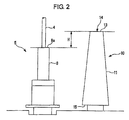
- FIG. 2 is a side elevational view showing a raw material gas supply nozzle and an electrode in the reactor for Polycrystalline silicon.
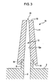
- FIG. 3 is a longitudinal sectional view showing the raw material gas supply nozzle of the reactor for polycrystalline silicon.
- FIG. 4 is a longitudinal sectional view showing an exemplified variation of the raw material gas supply nozzle.
- FIG. 1 is a schematic pattern diagram of the reactor for Polycrystalline silicon.
- FIG. 2 is a side elevational view showing a raw material gas supply nozzle and an electrode used in the reactor for polycrystalline silicon.
- FIG. 3 is a longitudinal sectional view of the raw material gas supply nozzle.
- the reactor for polycrystalline silicon 1 of the present embodiment is provided with a bell jar 3 formed in a bell shape so as to cover entirely a space above the bottom of the reactor 2 mounted in a circular shape.
- the interior of the reactor for polycrystalline silicon 1 is sealed hermetically by the bottom of the reactor 2 and the bell jar 3.
- a plurality of silicon seed rods 4 which are formed approximately in a ⁇ -shape, with the upper ends being connected to each other, and serving as a seed rod of the produced polycrystalline silicon are installed upright in the hermetically sealed interior. Both base ends of the silicon seed rod 4 are supported by the electrode 5 on the bottom of the reactor 2.
- the electrode 5 is made of carbon and formed approximately in a multi-stage cylindrical shape.
- a seed-rod retaining electrode 8 is arranged at the upper part of the electrode 5.
- An opening of a predetermined depth is provided at an upper end 8a of the seed-rod retaining electrode 8.
- One end of the silicon seed rod 4 is inserted into the opening, by which the silicon seed rod 4 is firmly retained by the seed -rod retaining electrode 8 of the electrode 5.
- a plurality of raw material gas supply ports 6 are formed on the bottom of the reactor 2 so that a cylindrical opening is allowed to face upward.
- the raw material gas supply port 6 supplies a raw material gas which is a mixed gas of chlorosilane with hydrogen to the silicon seed rod 4 inside the reactor for Polycrystalline silicon 1.
- a plurality of the raw material gas supply ports 6 are arranged at appropriate intervals with each other in such a manner that the raw material gas can be supplied uniformly to a plurality of the silicon seed rods 4.
- the raw material gas supply port 6 is connected to a raw material gas supply channel 9 opened on the bottom of the reactor 2.
- the raw material gas supply channel 9 is connected to a supply source of the raw material gas via a flow rate control valve (not illustrated). Therefore, the raw material gas is delivered to the raw material gas supply port 6 via the raw material gas supply channel 9, while the supply rate is controlled by the flow rate control valve.
- a raw material gas supply nozzle 10 made of carbon is attached at the upper part of the raw material gas supply port 6.
- the raw material gas supply nozzle 10 is formed in a tapered cylindrical shape so that the outer circumferential side face 11 and the inner circumferential side face 12a of a through-hole 12 installed on the interior are reduced in diameter upward.
- the through-hole 12 is opened on a minor diameter face 13, which is the tip of the tapered part, and an opening 14 is formed on the minor diameter face 13.
- a cylindrical hole 16 having a central axis which is aligned with a central axis of the through-hole 12 is formed on a major diameter face 15 which is the end face on the opposite side of the minor diameter face 13. Then, the cylindrical hole 16 is fitted into the raw material gas supply port 6, by which the raw material gas supply nozzle 10 is attached to the raw material gas supply port 6.
- a height of the minor diameter face 13, which is the upper end of the raw material gas supply nozzle 10, is set so that a relative height H with respect to the upper end 8a is in a range from -10 cm to +5 cm on the basis of a height of the upper end 8a of the seed-rod retaining electrode 8 of the electrode 5.
- the height H be set in a range from -5 cm to +1 cm.
- a height of the minor diameter face 13 at the upper end of the raw material gas supply nozzle 10 is set to be approximately equal to that of the upper end 8a (H ⁇ 0) on the basis of the upper end 8a of the electrode 5.
- a discharge port 7 is provided for discharging a gas developed after the rawmaterial gas supplied from the raw material gas supply port 6 reacts on the silicon seed rod 4.
- a plurality of the discharge ports 7 are arranged at appropriate intervals so that the gas after the reaction can be uniformly discharged.
- the rawmaterial gas supply nozzle 10 is attached to the raw material gas supply port 6 for supplying a raw material gas into the reactor for polycrystalline silicon 1 so as to be communicatively connected to the through- hole 12 of the raw material gas supply nozzle 10, by which the raw material gas is supplied into the reactor for polycrystalline silicon 1 via the raw material gas supply nozzle 10 from the opening 14.
- the minor diameter face 13 at the upper end of the raw material gas supply nozzle 10 is set to be a height greater than 5 cm on the basis of the upper end 8a of the electrode 5, the raw material gas is less likely to be supplied to the lower part of the silicon seed rod 4. Therefore, there is a concern that undesirable morphology may be formed at the lower part of the produced column-shaped polycrystalline silicon.
- the upper end of the raw material gas supply nozzle 10 is set to be a height less than -10 cm on the basis of the upper end of the electrode 5, it is difficult that the raw material gas arrives at the upper part inside the reactor. Therefore, the u undesirable morphology may be formed easily at the upper part of the column-shaped polycrystalline silicon.
- a height of the minor diameter face 13 at the upper end of the raw material gas supply nozzle 10 is set to be approximately equal to that of the upper end 8a on the basis of the upper end 8a of the electrode 5.
- the height H satisfies the condition that it is included in a range from -10 cm or more to +5 cm or less, the raw material gas can be delivered uniformly in a whole area of the silicon seed rod 4 from the upper part to the lower part. As a result, it is possible to effectively prevent the produced column-shaped Polycrystalline silicon from formation of undesirable morphology.
- the height of the minor diameter face 13 at the upper end of the raw material gas supply nozzle 10 also satisfies the condition that the height H is included in a range from -5 cm to +1 cm on the basis of the upper end 8a of the electrode 5, there is no chance that the lower face of a movable work table used in removing the silicon rod from the electrode 5 is in contact with the upper end of the raw material gas supply nozzle 10. As a result, it is possible to work smoothly. During the work, it is also possible to decrease such a risk that polycrystalline silicon may contact the raw material gas supply nozzle 10. On the other hand, the raw material gas can be supplied enough to the upper part inside the reactor.
- the outer circumferential side face 11 of the raw material gas supply nozzle 10 is formed in a tapered shape which reduces in diameter upward, it is possible to greatly decrease a volume percentage of the raw material gas supply nozzle 10 in the reactor. Thereby, when the silicon rod is removed from the seed-rod retaining electrode 8 of the electrode 5, it is possible to decrease such a risk that the silicon rod 4 may contact the rawmaterial gas supply nozzle 10. As a result, it is possible to perform the work smoothly.
- Table 1 shows the conditions for producing polycrystalline silicon.
- the pop-corn like surface at the lower part of the deposited column-shaped polycrystalline silicon was measured for length as a lower-part undesirable morphology, and a part having a smooth surface at an intermediate part excluding the upper-part and lower-part undesirable morphology was measured for length as a surface smooth part. Then, a determination was made of a percentage of the length of the undesirable morphology, that of the length of the surface smooth part, and that of the length of the upper-part undesirable morphology.
- Table 2 shows how the percentage of length of the surface smooth part changes, depending on the height of the nozzle.
- the height of the nozzle is expressed by a relative position of the electrode-retaining portion with respect to the upper end 8a.
- the percentage of the length of the lower-part undesirable morphology, that of the length of the upper-part undesirable morphology, and that of the length of the surface smooth part will be defined by the following formulae.
- FIG. 4 shows an exemplified variation of the raw material gas supply nozzle of the present invention.
- the raw material gas supply nozzle 21 is constituted with a nozzle main body 22 and a nozzle head 23.
- the nozzle main body 22 is formed in a tapered shaped in such a manner that the outer circumferential side face 11 thereof is reduced in diameter upward as with that shown in FIG. 3 .
- the inner circumferential side face 24a of the through-hole 24 is formed in a straight shape.
- a female thread portion 24b is formed at the upper end of the through-hole 24, and a nozzle head 23 is attached to the female thread portion 24b.
- the nozzle head 23 is formed so as to give a step between a major diameter portion 25 and a minor diameter portion 26.
- the opening 14 as the raw material gas supply nozzle 21 is formed by the through-hole 27 of the nozzle head 23.
- the upper end face 23a of the nozzle head 23 is set so that the relative height H is included in the above-described positional relationship on the basis of a height of the upper end 8a of the electrode 5, that is, in a range from -10 cm to +5 cm, preferably from -5 cm to +1 cm.
- the constituted raw material gas supply nozzle 21 can be exchanged only for the nozzle head 23, if necessary, because the nozzle head 23 installed at the tip thereof is attached in a removable manner. Since silicon is deposited at the tip of the raw material gas supply nozzle 21, for example, in association with production of Polycrystalline silicon, such work is conducted so that the silicon deposited on the raw material gas supply nozzle 21 is removed after product ion of polycrystalline silicon is completed. However, the work to remove requires chipping or the like and the tip of the nozzle is liable to breakage. In the raw material gas supply nozzle shown in FIG. 3 , it is necessary to exchange the nozzle in its entirety, if the tip is broken. However, in the raw material gas supply nozzle 21 shown in FIG.
- the nozzle main body 22 can be used again as it is. Further, in a case where the tip of the nozzle is damaged by rods of polycrystalline silicon or the like, the nozzle main body 22 can be used again by exchanging the nozzle head 23. Then, the cost of equipment can be reduced as compared with an integrally-built raw material gas supply nozzle shown in FIG. 3 .
- the through-holes 27 of the nozzle head 23 are formed to be made available in various types that are different in diameter. Then, the nozzle head 23 is used selectively to adjust the diameter of the opening 14 on the nozzle outlet side, by which it is possible to keep constant the flow rate of gas from the raw material gas supply nozzle 21, irrespective of the number of the raw material gas supply ports 6. As a result, it is possible to keep to a smaller extent variation in the quality of the produced Polycrystalline silicon.
- the reactor for polycrystalline silicon 1 which is an embodiment of the present invention.
- the present invention shall not be, however, restricted thereto and may be modified in any way within a scope not departing from the technical idea of the present invention.
- the cylindrical hole 16 of the raw material gas supply nozzle is fitted into the raw material gas supply port 6, by which the raw material gas supply nozzle is attached to the raw material gas supply port 6.
- a constitution may also be acceptable in which a female thread is made on the inner circumferential wall of the cylindrical hole 16, a male thread is made on the outer circumferential side face of the raw material gas supply port 6, and the male thread is screwed into the female thread, thereby the raw material gas supply nozzle 10 is attached to the raw material gas supply port 6.
Landscapes
- Chemical & Material Sciences (AREA)
- Organic Chemistry (AREA)
- Chemical Kinetics & Catalysis (AREA)
- Inorganic Chemistry (AREA)
- Engineering & Computer Science (AREA)
- Crystallography & Structural Chemistry (AREA)
- Materials Engineering (AREA)
- Metallurgy (AREA)
- Silicon Compounds (AREA)
Abstract
Description
- This application claims priority to Japanese Patent Application No.
2007-244352 filed on September 20, 2007 2008-177980 filed on July 8, 2008 - The present invention relates to a reactor for polycrystalline silicon used in producing polycrystalline silicon according to the Siemens method, and relates to a polycrystalline silicon production method.
- The Siemens method is known as a method for producing polycrystalline silicon of high purity used as a material of semiconductors. In the Siemens method, a raw material gas composed of chlorosilane and hydrogen is brought into contact with a heated silicon seed rod to deposit polycrystalline silicon on the surface through reactions of the raw material gas. A reactor for polycrystalline silicon in which many silicon seed rods are installed upright in a reactor is used as an apparatus for carrying out this production method. In general, the silicon seed rod is formed in a π-shape, with upper ends being coupled, and both lower ends thereof are fixed to an electrode mounted on the bottom of the reactor.
- Then, electricity is supplied through the electrode located on both ends to a whole part of the silicon seed rod, thereby heating the silicon seed rod in its entirety by Joule heat thereof to a temperature at which the raw material gas is thermally decomposed (for example, from about 1050°C to 1100°C). The raw material gas supplied into the reactor is in contact with the surface of the heated silicon seed rod to cause thermal decomposition or hydrogen reduction, thereby Polycrystalline silicon is deposited on the surface of the silicon seed rod. This reaction proceeds continuously, by which polycrystalline silicon grows in a column-shape (refer to Japanese Patent No.
2867306 - Into the reactor for polycrystalline silicon, a raw material gas is in general supplied from the bottom of the reactor. The raw material gas is supplied from a raw material gas supply port installed at the bottom of the reactor so as to be uniformly dispersed to all silicon seed rods in the reactor.
- Incidentally, when a raw material gas is directly blown toward the lower part of the column-shaped polycrystalline silicon heated by supply of electricity, the temperature of the lower part decreased compared to that of the other part, thereby the speed for growing polycrystalline silicon deposited on the surface of the column-shaped polycrystalline silicon is decreased. As a result, the lower part of the column-shaped polycrystalline silicon may be partially recessed to result in undesirable morphology. Further, the raw material gas is not sufficiently supplied and stagnates at the upper part of the column-shaped polycrystalline silicon. Thus, popcorn-like irregularities may be developed on the surface of silicon to result in undesirable morphology. When the undesirable morphology is generated, polycrystalline silicon may be deteriorated in quality to result in a lower yield.
- The present invention has been made in view of the above situation, an object of which is to provide a reactor for polycrystalline silicon capable of supplying stably a raw material gas to the surface of a silicon seed rod and preventing the undesirable morphology of polycrystalline silicon.
- The reactor for polycrystalline silicon of the present invention is a reactor for polycrystalline silicon in which a silicon seed rod installed inside the reactor is heated by supplying electricity, and a raw material gas supplied inside the reactor is allowed to react, thereby producing Polycrystalline silicon on the surface of the silicon seed rod. A raw material gas supply nozzle extending upward is attached to a raw material gas supply port installed at the bottom of the reactor so as to be communicatively connected, and the upper end of the raw material gas supply nozzle is set to a height in a range from -10 cm to +5 cm on the basis of the upper end of the electrode which retains the silicon seed rod. In other words, a height from the upper end of the electrode which retains the silicon seed rod to the upper end of the raw material gas supply nozzle is -10 cm or more to +5 cm or less.
- The raw material gas supply nozzle is attached to the raw material gas supply port for supplying a raw material gas into the reactor for polycrystalline silicon so as to be communicatively connected, by which the raw material gas is to be supplied into the reactor for polycrystalline silicon via the raw material gas supply nozzle. In this instance, when the upper end of the raw material gas supply nozzle extending upward is set to a height greater than +5 cm on the basis of the upper end of the electrode retaining the silicon seed rod, the raw material gas is difficult to supply to the lower part of the silicon seed rod, and there is a concern that undesirable morphology may take place at the lower part of the produced column-shaped polycrystalline silicon. On the other hand, when the upper end of the raw material gas supply nozzle is set to a height less than -10 cm on the basis of the upper end of the electrode, the raw material gas is less likely to arrive at the upper part inside the reactor, thereby the undesirable morphology may be formed easily at the upper part of the column-shaped polycrystalline silicon.
- In the present invention, with the above matters taken into account, the upper end of the raw material gas supply nozzle is set to a height in a range from -10 cm to +5 cm on the basis of the upper end of the electrode. Thereby, it is possible to supply uniformly the raw material gas to a whole area of the silicon seed rod from the upper part to the lower part. As a result, it is possible to effectively prevent the produced column-shaped polycrystalline silicon from formation of undesirable morphology.
- Further, in the reactor for polycrystalline silicon of the present invention, it is preferable that the upper end of the raw material gas supply nozzle be set to a height in a range from -5 cm to +1 cm on the basis of the upper end of the electrode which retains the silicon seed rod. In other words, a height from the upper end of the electrode retaining the silicon seed rod to the upper end of the raw material gas supply nozzle is preferably -5 cm or more to +1 cm or less.
- In the present invention, a height of the upper end of the raw material gas supply nozzle is at the highest about 1 cm higher than the upper end of the electrode. Therefore, there is no chance that the lower face of a movable work table used in removing the silicon rod from the electrode together with the produced polycrystalline silicon hits on the upper end of the raw material gas supply nozzle, thus making it possible to smoothly take out polycrystalline silicon. Further, during the work of removing the silicon rod from the electrode, it is possible to decrease such a risk that polycrystalline silicon may hit the raw material gas supply nozzle. On the other hand, since a height of the upper end of the raw material gas supply nozzle is at the lowest about 5 cm lower on the basis of the upper end of the electrode, it is possible to supply a sufficient quantity of the raw material gas to the upper space inside the reactor.
- Further, in the reactor for polycrystalline silicon of the present invention, it is preferable that the raw material gas supply nozzle be formed in a tapered cylindrical shape having an outer circumferential side face which is reduced in diameter as close to an upper end thereof.
- The raw material gas supply nozzle is formed in a tapered shape in which the outer circumferential side face is reduced in diameter upward. Therefore, it is possible to greatly decrease a volume percentage of the raw material gas supply nozzle in the reactor. For example, when a silicon rod is removed from the electrode, it is possible to decrease such a risk that the silicon rod may hit the raw material gas supply nozzle. As a result, it is possible to perform the work smoothly.
- Further, when broken pieces of polycrystalline silicon deposited on the surface of a silicon seed rod fall from above, the broken pieces will fall so as to slide along the tapered face of the raw material gas supply nozzle. Therefore, it is possible to avoid damage of the raw material gas supply nozzle. Still further, with the flow of a raw material gas supplied from the raw material gas supply nozzle to the upper space inside the reactor, the raw material gas remaining at the lower part inside the reactor is guided to the upper part along the tapered face. Thus, it is possible to effectively utilize the raw material gas remaining at the lower part in production for polycrystalline silicon.
- Still further in the reactor for Polycrystalline silicon of the present invention, the raw material gas supply nozzle may comprise a nozzle main body and a nozzle head which is installed to the tip of the nozzle main body in a removable manner.
In the production of polycrystalline silicon, since silicon is deposited on the tip of the raw material gas supply nozzle as well to reduce the inner diameter of the nozzle, silicon is removed from the raw material gas supply nozzle by chipping or the like after the production of polycrystalline silicon is completed. In this instance, the nozzle tip is liable to breakage. In the reactor for polycrystalline silicon of the present invention, the nozzle head is installed in a removable manner, thereby only the nozzle head may be exchanged. It is, therefore, possible to effectively use the main body thereof. - A polycrystalline silicon production method of the present invention, including: heating a silicon seed rod installed inside a reactor for polycrystalline silicon by supplying electricity; and reacting a raw material gas supplied inside the reactor through a raw material gas supply port installed on the bottom of the reactor and a raw material gas supply nozzle which extends upward and which is attached to the raw material gas supply port so as to be communicatively connected, thereby producing polycrystalline silicon on the surface of the silicon seed rod; wherein the upper end of the raw material gas supply nozzle is set to a height in a range from -10 cm to +5 cm on the basis of the upper end of the electrode which retains the silicon seed rod.
- According to the reactor for polycrystalline silicon of the present invention, it is possible to stably supply a raw material gas to the surface of a silicon seed rod and prevent polycrystalline silicon from formation of undesirable morphology.
-
FIG. 1 is a schematic pattern diagram of a reactor for polycrystalline silicon.
FIG. 2 is a side elevational view showing a raw material gas supply nozzle and an electrode in the reactor for Polycrystalline silicon.
FIG. 3 is a longitudinal sectional view showing the raw material gas supply nozzle of the reactor for polycrystalline silicon.
FIG. 4 is a longitudinal sectional view showing an exemplified variation of the raw material gas supply nozzle. - Hereinafter, an explanation will be made of a reactor for polycrystalline silicon which is an embodiment of the present invention by referring to drawings.
FIG. 1 is a schematic pattern diagram of the reactor for Polycrystalline silicon.FIG. 2 is a side elevational view showing a raw material gas supply nozzle and an electrode used in the reactor for polycrystalline silicon.FIG. 3 is a longitudinal sectional view of the raw material gas supply nozzle. - As shown in
FIG. 1 , the reactor forpolycrystalline silicon 1 of the present embodiment is provided with a bell jar 3 formed in a bell shape so as to cover entirely a space above the bottom of the reactor 2 mounted in a circular shape. The interior of the reactor forpolycrystalline silicon 1 is sealed hermetically by the bottom of the reactor 2 and the bell jar 3. A plurality ofsilicon seed rods 4 which are formed approximately in a π-shape, with the upper ends being connected to each other, and serving as a seed rod of the produced polycrystalline silicon are installed upright in the hermetically sealed interior. Both base ends of thesilicon seed rod 4 are supported by the electrode 5 on the bottom of the reactor 2. - The electrode 5 is made of carbon and formed approximately in a multi-stage cylindrical shape. A seed-
rod retaining electrode 8 is arranged at the upper part of the electrode 5. An opening of a predetermined depth is provided at anupper end 8a of the seed-rod retaining electrode 8. One end of thesilicon seed rod 4 is inserted into the opening, by which thesilicon seed rod 4 is firmly retained by the seed -rod retaining electrode 8 of the electrode 5. - Further, a plurality of raw material
gas supply ports 6 are formed on the bottom of the reactor 2 so that a cylindrical opening is allowed to face upward. The raw materialgas supply port 6 supplies a raw material gas which is a mixed gas of chlorosilane with hydrogen to thesilicon seed rod 4 inside the reactor forPolycrystalline silicon 1. A plurality of the raw materialgas supply ports 6 are arranged at appropriate intervals with each other in such a manner that the raw material gas can be supplied uniformly to a plurality of thesilicon seed rods 4. As shown inFIG. 3 , the raw materialgas supply port 6 is connected to a raw material gas supply channel 9 opened on the bottom of the reactor 2. The raw material gas supply channel 9 is connected to a supply source of the raw material gas via a flow rate control valve (not illustrated). Therefore, the raw material gas is delivered to the raw materialgas supply port 6 via the raw material gas supply channel 9, while the supply rate is controlled by the flow rate control valve. - Then, as shown in
FIG. 2 andFIG. 3 , a raw materialgas supply nozzle 10 made of carbon is attached at the upper part of the raw materialgas supply port 6. The raw materialgas supply nozzle 10 is formed in a tapered cylindrical shape so that the outercircumferential side face 11 and the innercircumferential side face 12a of a through-hole 12 installed on the interior are reduced in diameter upward. The through-hole 12 is opened on aminor diameter face 13, which is the tip of the tapered part, and anopening 14 is formed on theminor diameter face 13. - Further, on a
major diameter face 15 which is the end face on the opposite side of theminor diameter face 13, acylindrical hole 16 having a central axis which is aligned with a central axis of the through-hole 12 is formed. Then, thecylindrical hole 16 is fitted into the raw materialgas supply port 6, by which the raw materialgas supply nozzle 10 is attached to the raw materialgas supply port 6. A height of theminor diameter face 13, which is the upper end of the raw materialgas supply nozzle 10, is set so that a relative height H with respect to theupper end 8a is in a range from -10 cm to +5 cm on the basis of a height of theupper end 8a of the seed-rod retaining electrode 8 of the electrode 5. It is more preferable that the height H be set in a range from -5 cm to +1 cm. In the present embodiment, in order to satisfy the above conditions, a height of theminor diameter face 13 at the upper end of the raw materialgas supply nozzle 10 is set to be approximately equal to that of theupper end 8a (H≈0) on the basis of theupper end 8a of the electrode 5. - At the bottom of the reactor 2 a discharge port 7 is provided for discharging a gas developed after the rawmaterial gas supplied from the raw material
gas supply port 6 reacts on thesilicon seed rod 4. A plurality of the discharge ports 7 are arranged at appropriate intervals so that the gas after the reaction can be uniformly discharged. - In the present embodiment, the rawmaterial
gas supply nozzle 10 is attached to the raw materialgas supply port 6 for supplying a raw material gas into the reactor forpolycrystalline silicon 1 so as to be communicatively connected to the through-hole 12 of the raw materialgas supply nozzle 10, by which the raw material gas is supplied into the reactor forpolycrystalline silicon 1 via the raw materialgas supply nozzle 10 from theopening 14. In this instance, in a case where theminor diameter face 13 at the upper end of the raw materialgas supply nozzle 10 is set to be a height greater than 5 cm on the basis of theupper end 8a of the electrode 5, the raw material gas is less likely to be supplied to the lower part of thesilicon seed rod 4. Therefore, there is a concern that undesirable morphology may be formed at the lower part of the produced column-shaped polycrystalline silicon. On the other hand, in a case where the upper end of the raw materialgas supply nozzle 10 is set to be a height less than -10 cm on the basis of the upper end of the electrode 5, it is difficult that the raw material gas arrives at the upper part inside the reactor. Therefore, the u undesirable morphology may be formed easily at the upper part of the column-shaped polycrystalline silicon. - In the present embodiment, with the above matters taken into account, a height of the
minor diameter face 13 at the upper end of the raw materialgas supply nozzle 10 is set to be approximately equal to that of theupper end 8a on the basis of theupper end 8a of the electrode 5. In other words, since the height H satisfies the condition that it is included in a range from -10 cm or more to +5 cm or less, the raw material gas can be delivered uniformly in a whole area of thesilicon seed rod 4 from the upper part to the lower part. As a result, it is possible to effectively prevent the produced column-shaped Polycrystalline silicon from formation of undesirable morphology. - Further, since the height of the
minor diameter face 13 at the upper end of the raw materialgas supply nozzle 10 also satisfies the condition that the height H is included in a range from -5 cm to +1 cm on the basis of theupper end 8a of the electrode 5, there is no chance that the lower face of a movable work table used in removing the silicon rod from the electrode 5 is in contact with the upper end of the raw materialgas supply nozzle 10. As a result, it is possible to work smoothly. During the work, it is also possible to decrease such a risk that polycrystalline silicon may contact the raw materialgas supply nozzle 10. On the other hand, the raw material gas can be supplied enough to the upper part inside the reactor. - Still further, since the outer circumferential side face 11 of the raw material
gas supply nozzle 10 is formed in a tapered shape which reduces in diameter upward, it is possible to greatly decrease a volume percentage of the raw materialgas supply nozzle 10 in the reactor. Thereby, when the silicon rod is removed from the seed-rod retaining electrode 8 of the electrode 5, it is possible to decrease such a risk that thesilicon rod 4 may contact the rawmaterialgas supply nozzle 10. As a result, it is possible to perform the work smoothly. - In addition, in a case where broken pieces of polycrystalline silicon deposited on the surface of the
silicon seed rod 4 fall from above, the broken pieces will fall so as to slide along the tapered outer circumferential side face 11 of the raw materialgas supply nozzle 10. Therefore, it is possible to avoid damage of the raw materialgas supply nozzle 10. Further, with the flow of a raw material gas supplied from the raw materialgas supply nozzle 10 to the upper space inside the reactor, the raw material gas remaining at the lower part inside the reactor is guided to the upper part along the tapered outercircumferential side face 11. Thus, it is possible to effectively utilize the raw material gas remaining at the lower part for production of polycrystalline silicon. - Next, an explanation will be made of the result of a study conducted for confirming the effect of the raw material
gas supply nozzle 10.
In this study, a nozzle adjustable for the height of the raw materialgas supply nozzle 10 to various levels on the basis of theupper end 8a of the electrode retaining portion as shown in Table 2 was fitted into the raw materialgas supply port 6, and a raw material gas was supplied thereto.
In order to confirm the effect, an evaluation was made by the surface of column-shaped polycrystalline silicon.
Polycrystalline silicon is given a pop-corn like surface when the raw material gas is insufficiently supplied. It is said that Polycrystalline silicon is determined to be higher in quality, if smoother. Therefore, the study was conducted to determine to what extent an area of the smooth surface would be changed depending on the height of the raw material gas supply nozzle.
Table 1 shows the conditions for producing polycrystalline silicon. The pop-corn like surface at the lower part of the deposited column-shaped polycrystalline silicon was measured for length as a lower-part undesirable morphology, and a part having a smooth surface at an intermediate part excluding the upper-part and lower-part undesirable morphology was measured for length as a surface smooth part. Then, a determination was made of a percentage of the length of the undesirable morphology, that of the length of the surface smooth part, and that of the length of the upper-part undesirable morphology. Table 2 shows how the percentage of length of the surface smooth part changes, depending on the height of the nozzle. - In Table 2, the height of the nozzle is expressed by a relative position of the electrode-retaining portion with respect to the
upper end 8a.
Further, the percentage of the length of the lower-part undesirable morphology, that of the length of the upper-part undesirable morphology, and that of the length of the surface smooth part will be defined by the following formulae.


The percentage of the length of the upper-part undesirable morphology was calculated by the above formula, because as described above, the silicon seed rod was assembled in a inversed U-shape and each column-shaped polycrystalline silicon was determined in a state in which it was taken out, by which it was difficult to identify the border line accurately due to cracks or the like found at the upper coupling part formed in the inversed U-shape. -
(Table 1) production conditions Supply of raw material gas Trichlorosilane 216-228Ton Hydrogen 273,000-288,000m3 Reaction time 114 hours to 119 hours Outer diameter of column-shaped polycrystalline silicon 11.8-12.4cm (Table 2) Comparative example Present invention Comparative example Height of nozzle (cm) (Relative height H to 8a) -15 -10 -7 -5 0 +1 +2 +5 +10 percentage of length of lower-part undesirable morphology (%) 16.5 18.0 18.2 18.6 19.0 20.9 21.8 23.4 29.5 Percentage of length of upper-part undesirable morphology (%) 42.7 33.1 30.1 27.6 26.1 26.0 25.4 25.3 24.1 Percentage of length of surface smooth part (%) 40.8 48.9 51.7 53.8 54.9 53.1 52.8 51.3 46.4 - As is apparent from Table 2, in a case where the height of the nozzle (relative height H) is in a range from -15 cm and +10 cm, a greater percentage of the upper-part or the lower-part undesirable morphology of column-shaped polycrystalline silicon is observed. Therefore, a percentage of the length of the intermediate surface smooth part is decreased to result in a poor product yield. On the other hand, in a case where the height of the nozzle (relative height H) is in a range from -10 cm to +5 cm, the surface smooth part can be occupied more than half the entire length of the column-shaped Polycrystalline silicon, in particular, favorably in a case where the height is in a range from -5 cm to +1 cm.
-
FIG. 4 shows an exemplified variation of the raw material gas supply nozzle of the present invention.
The raw materialgas supply nozzle 21 is constituted with a nozzlemain body 22 and anozzle head 23. The nozzlemain body 22 is formed in a tapered shaped in such a manner that the outer circumferential side face 11 thereof is reduced in diameter upward as with that shown inFIG. 3 . However, the innercircumferential side face 24a of the through-hole 24 is formed in a straight shape. Further, afemale thread portion 24b is formed at the upper end of the through-hole 24, and anozzle head 23 is attached to thefemale thread portion 24b. Thenozzle head 23 is formed so as to give a step between amajor diameter portion 25 and aminor diameter portion 26. Amale thread portion 26a, which is screwed into thefemale thread portion 24b of the nozzlemain body 22, is formed at theminor diameter portion 26. Further, a through-hole 27 smaller in diameter than the through-hole 24 of the nozzlemain body 22 is formed at the center of thenozzle head 23. In a state that thenozzle head 23 is screwed into the nozzlemain body 22, both through-holes opening 14 as the raw materialgas supply nozzle 21 is formed by the through-hole 27 of thenozzle head 23.
In the raw materialgas supply nozzle 21, the upper end face 23a of thenozzle head 23 is set so that the relative height H is included in the above-described positional relationship on the basis of a height of theupper end 8a of the electrode 5, that is, in a range from -10 cm to +5 cm, preferably from -5 cm to +1 cm. - The constituted raw material
gas supply nozzle 21 can be exchanged only for thenozzle head 23, if necessary, because thenozzle head 23 installed at the tip thereof is attached in a removable manner.
Since silicon is deposited at the tip of the raw materialgas supply nozzle 21, for example, in association with production of Polycrystalline silicon, such work is conducted so that the silicon deposited on the raw materialgas supply nozzle 21 is removed after product ion of polycrystalline silicon is completed. However, the work to remove requires chipping or the like and the tip of the nozzle is liable to breakage. In the raw material gas supply nozzle shown inFIG. 3 , it is necessary to exchange the nozzle in its entirety, if the tip is broken. However, in the raw materialgas supply nozzle 21 shown inFIG. 4 , only thenozzle head 23 may be exchanged and the nozzlemain body 22 can be used again as it is. Further, in a case where the tip of the nozzle is damaged by rods of polycrystalline silicon or the like, the nozzlemain body 22 can be used again by exchanging thenozzle head 23. Then, the cost of equipment can be reduced as compared with an integrally-built raw material gas supply nozzle shown inFIG. 3 . - Further, the through-
holes 27 of thenozzle head 23 are formed to be made available in various types that are different in diameter. Then, thenozzle head 23 is used selectively to adjust the diameter of theopening 14 on the nozzle outlet side, by which it is possible to keep constant the flow rate of gas from the raw materialgas supply nozzle 21, irrespective of the number of the raw materialgas supply ports 6. As a result, it is possible to keep to a smaller extent variation in the quality of the produced Polycrystalline silicon. - An explanation has been so far made of the reactor for
polycrystalline silicon 1, which is an embodiment of the present invention. The present invention shall not be, however, restricted thereto and may be modified in any way within a scope not departing from the technical idea of the present invention. For example, in the present embodiment, thecylindrical hole 16 of the raw material gas supply nozzle is fitted into the raw materialgas supply port 6, by which the raw material gas supply nozzle is attached to the raw materialgas supply port 6. However, a constitution may also be acceptable in which a female thread is made on the inner circumferential wall of thecylindrical hole 16, a male thread is made on the outer circumferential side face of the raw materialgas supply port 6, and the male thread is screwed into the female thread, thereby the raw materialgas supply nozzle 10 is attached to the raw materialgas supply port 6.
Claims (5)
- A reactor for polycrystalline silicon in which a silicon seed rod installed inside the reactor is heated by supplying electricity, a raw material gas supplied inside the reactor is allowed to react, thereby producing polycrystalline silicon on the surface of the silicon seed rod,
the reactor for Polycrystalline silicon, comprising:a raw material gas supply port installed on the bottom of the reactor; anda raw material gas supply nozzle which extends upward and which is attached to the raw material gas supply port so as to be communicatively connected, whereinthe upper end of the raw material gas supply nozzle is set to a height in a range from -10 cm to +5 cm on the basis of the upper end of the electrode which retains the silicon seed rod. - The reactor for polycrystalline silicon according to claim 1, wherein
the upper end of the raw material gas supply nozzle is set to a height in a range from -5 cm to +1 cm on the basis of the upper end of the electrode which retains the silicon seed rod. - The reactor for polycrystalline silicon according to claim 1 or claim 2, wherein
the raw material gas supply nozzle is formed in a tapered cylindrical shape having an outer circumferential side face which is reduced in diameter as close to an upper end thereof. - The reactor for polycrystalline silicon according to any one of claims 1 to 3, wherein
the raw material gas supply nozzle comprises a nozzle main body and a nozzle head which is installed to the tip of the nozzle main body in a removable manner. - A polycrystalline silicon production method, comprising:heating a silicon seed rod installed inside a reactor for polycrystalline silicon by supplying electricity; andreacting a raw material gas supplied inside the reactor through a raw material gas supply port installed on the bottom of the reactor and a raw material gas supply nozzle which extends upward and which is attached to the raw material gas supply port so as to be communicatively connected, thereby producing polycrystalline silicon on the surface of the silicon seed rod; wherein
the upper end of the raw material gas supply nozzle is set to a height in a range from -10 cm to +5 cm on the basis of the upper end of the electrode which retains the silicon seed rod.
Applications Claiming Priority (2)
| Application Number | Priority Date | Filing Date | Title |
|---|---|---|---|
| JP2007244352 | 2007-09-20 | ||
| JP2008177980 | 2008-07-08 |
Publications (3)
| Publication Number | Publication Date |
|---|---|
| EP2039653A2 true EP2039653A2 (en) | 2009-03-25 |
| EP2039653A3 EP2039653A3 (en) | 2009-05-27 |
| EP2039653B1 EP2039653B1 (en) | 2015-12-23 |
Family
ID=40289162
Family Applications (1)
| Application Number | Title | Priority Date | Filing Date |
|---|---|---|---|
| EP08164540.0A Active EP2039653B1 (en) | 2007-09-20 | 2008-09-17 | Reactor for polycrystalline silicon and polycrystalline silicon production method |
Country Status (6)
| Country | Link |
|---|---|
| US (2) | US8231724B2 (en) |
| EP (1) | EP2039653B1 (en) |
| JP (1) | JP5476693B2 (en) |
| KR (1) | KR101811872B1 (en) |
| CN (1) | CN101392408B (en) |
| RU (1) | RU2470098C2 (en) |
Cited By (4)
| Publication number | Priority date | Publication date | Assignee | Title |
|---|---|---|---|---|
| EP2108619A3 (en) * | 2008-03-21 | 2010-01-06 | Mitsubishi Materials Corporation | Polycrystalline silicon reactor |
| EP2077252A3 (en) * | 2007-11-28 | 2011-03-02 | Mitsubishi Materials Corporation | Polycrystalline silicon manufacturing apparatus and manufacturing method |
| DE102010000270A1 (en) * | 2010-02-01 | 2011-08-04 | G+R Technology Group AG, 93128 | Electrode for a reactor for the production of polycrystalline silicon |
| CN111936420A (en) * | 2018-04-05 | 2020-11-13 | 株式会社德山 | Method for producing polycrystalline silicon rod and reaction furnace |
Families Citing this family (16)
| Publication number | Priority date | Publication date | Assignee | Title |
|---|---|---|---|---|
| US7922814B2 (en) * | 2005-11-29 | 2011-04-12 | Chisso Corporation | Production process for high purity polycrystal silicon and production apparatus for the same |
| EP2039653B1 (en) * | 2007-09-20 | 2015-12-23 | Mitsubishi Materials Corporation | Reactor for polycrystalline silicon and polycrystalline silicon production method |
| JP4854639B2 (en) * | 2007-10-30 | 2012-01-18 | 株式会社大阪チタニウムテクノロジーズ | Method for producing polycrystalline silicon |
| EP2271587A1 (en) * | 2008-03-26 | 2011-01-12 | GT Solar Incorporated | Gold-coated polysilicon reactor system and method |
| EP2271788A2 (en) * | 2008-03-26 | 2011-01-12 | GT Solar Incorporated | Systems and methods for distributing gas in a chemical vapor deposition reactor |
| CN101775643B (en) * | 2009-12-23 | 2012-06-13 | 洛阳金诺机械工程有限公司 | Manufacture technology of whole U-shaped silicon core |
| JP5699060B2 (en) | 2011-09-20 | 2015-04-08 | 信越化学工業株式会社 | Method for producing polycrystalline silicon |
| KR101302231B1 (en) * | 2012-02-22 | 2013-09-02 | 최진석 | Two Pieces Graphite Chuck |
| KR101311739B1 (en) * | 2013-01-14 | 2013-10-14 | 주식회사 아이제이피에스 | Polysilicon Manufacturing Equipment |
| DE102013207251A1 (en) | 2013-04-22 | 2014-10-23 | Wacker Chemie Ag | Process for producing polycrystalline silicon |
| CN104973600B (en) * | 2014-04-01 | 2017-01-25 | 新特能源股份有限公司 | Polycrystalline silicon production method |
| CN106517211B (en) * | 2016-11-29 | 2018-11-09 | 陈生辉 | A kind of device producing polysilicon and its application |
| CN106865551B (en) * | 2017-03-24 | 2017-12-19 | 亚洲硅业(青海)有限公司 | Nozzle for 48 pairs of rod polycrystalline silicon reducing furnaces |
| CN108193267A (en) * | 2018-01-25 | 2018-06-22 | 山东大海新能源发展有限公司 | A kind of polysilicon ingot casting equipment |
| CN118541331A (en) * | 2022-01-18 | 2024-08-23 | 株式会社德山 | Reactor for manufacturing polycrystalline silicon rod, gas supply nozzle, method for manufacturing polycrystalline silicon rod, and polycrystalline silicon rod |
| CN117088374A (en) * | 2023-08-02 | 2023-11-21 | 浙江大学高端装备研究院 | A kind of split trough silane thermal decomposition furnace |
Citations (3)
| Publication number | Priority date | Publication date | Assignee | Title |
|---|---|---|---|---|
| JP2867306B2 (en) | 1991-11-15 | 1999-03-08 | 三菱マテリアルポリシリコン株式会社 | Method and apparatus for producing semiconductor grade polycrystalline silicon |
| JP2007244352A (en) | 2006-03-14 | 2007-09-27 | Tsuneo Kanbe | Holding tool for fishing rod, equipped with movable elbow supporter |
| JP2008177980A (en) | 2007-01-22 | 2008-07-31 | Sony Corp | Speaker device |
Family Cites Families (13)
| Publication number | Priority date | Publication date | Assignee | Title |
|---|---|---|---|---|
| GB922280A (en) * | 1954-05-18 | 1963-03-27 | Siemens Ag | Improvements in or relating to processes and apparatus for the production of ultra-pure semiconductor substances |
| US3011877A (en) * | 1956-06-25 | 1961-12-05 | Siemens Ag | Production of high-purity semiconductor materials for electrical purposes |
| DE1061593B (en) * | 1956-06-25 | 1959-07-16 | Siemens Ag | Device for obtaining the purest semiconductor material for electrotechnical purposes |
| NL123477C (en) | 1958-05-16 | |||
| NL124690C (en) * | 1958-05-29 | |||
| US3820935A (en) * | 1971-10-04 | 1974-06-28 | Siemens Ag | Method and device for the production of tubular members of silicon |
| DE2912661C2 (en) | 1979-03-30 | 1982-06-24 | Wacker-Chemitronic Gesellschaft Fuer Elektronik-Grundstoffe Mbh, 8263 Burghausen | Process for the deposition of pure semiconductor material and nozzle for carrying out the process |
| US5611491A (en) * | 1995-02-27 | 1997-03-18 | Hughes Aircraft Company | Modular CO2 jet spray device |
| DE10315386A1 (en) * | 2003-04-04 | 2004-10-14 | Glatt Ingenieurtechnik Gmbh | Nozzle for spraying liquids, dispersions, emulsions or suspensions |
| CN2708213Y (en) * | 2004-07-08 | 2005-07-06 | 成都蜀菱贸易发展有限公司 | Polysilicon hydrogen reducing furnace |
| CN1884068A (en) * | 2005-06-24 | 2006-12-27 | 刘雅銘 | Reducing furnace for producing polysilicon |
| EP2039653B1 (en) * | 2007-09-20 | 2015-12-23 | Mitsubishi Materials Corporation | Reactor for polycrystalline silicon and polycrystalline silicon production method |
| CN102959620B (en) | 2011-02-14 | 2015-05-13 | 弗兰霍菲尔运输应用研究公司 | Information signal representation using lapped transform |
-
2008
- 2008-09-17 EP EP08164540.0A patent/EP2039653B1/en active Active
- 2008-09-17 KR KR1020080090993A patent/KR101811872B1/en active Active
- 2008-09-18 JP JP2008239033A patent/JP5476693B2/en active Active
- 2008-09-18 CN CN200810215096.8A patent/CN101392408B/en active Active
- 2008-09-18 RU RU2008137427/05A patent/RU2470098C2/en active
- 2008-09-19 US US12/232,612 patent/US8231724B2/en not_active Expired - Fee Related
-
2012
- 2012-06-27 US US13/534,181 patent/US8790429B2/en active Active
Patent Citations (3)
| Publication number | Priority date | Publication date | Assignee | Title |
|---|---|---|---|---|
| JP2867306B2 (en) | 1991-11-15 | 1999-03-08 | 三菱マテリアルポリシリコン株式会社 | Method and apparatus for producing semiconductor grade polycrystalline silicon |
| JP2007244352A (en) | 2006-03-14 | 2007-09-27 | Tsuneo Kanbe | Holding tool for fishing rod, equipped with movable elbow supporter |
| JP2008177980A (en) | 2007-01-22 | 2008-07-31 | Sony Corp | Speaker device |
Cited By (7)
| Publication number | Priority date | Publication date | Assignee | Title |
|---|---|---|---|---|
| EP2077252A3 (en) * | 2007-11-28 | 2011-03-02 | Mitsubishi Materials Corporation | Polycrystalline silicon manufacturing apparatus and manufacturing method |
| US8329132B2 (en) | 2007-11-28 | 2012-12-11 | Mitsubishi Materials Corporation | Polycrystalline silicon manufacturing apparatus and manufacturing method |
| EP2108619A3 (en) * | 2008-03-21 | 2010-01-06 | Mitsubishi Materials Corporation | Polycrystalline silicon reactor |
| US8703248B2 (en) | 2008-03-21 | 2014-04-22 | Mitsubishi Materials Corporation | Polycrystalline silicon reactor |
| DE102010000270A1 (en) * | 2010-02-01 | 2011-08-04 | G+R Technology Group AG, 93128 | Electrode for a reactor for the production of polycrystalline silicon |
| CN111936420A (en) * | 2018-04-05 | 2020-11-13 | 株式会社德山 | Method for producing polycrystalline silicon rod and reaction furnace |
| CN111936420B (en) * | 2018-04-05 | 2023-08-18 | 株式会社德山 | Method for producing polycrystalline silicon rod and reaction furnace |
Also Published As
| Publication number | Publication date |
|---|---|
| EP2039653B1 (en) | 2015-12-23 |
| US20090081380A1 (en) | 2009-03-26 |
| CN101392408A (en) | 2009-03-25 |
| US8231724B2 (en) | 2012-07-31 |
| KR101811872B1 (en) | 2017-12-22 |
| US20120266820A1 (en) | 2012-10-25 |
| KR20090031254A (en) | 2009-03-25 |
| RU2470098C2 (en) | 2012-12-20 |
| JP2010037180A (en) | 2010-02-18 |
| JP5476693B2 (en) | 2014-04-23 |
| CN101392408B (en) | 2014-03-05 |
| RU2008137427A (en) | 2010-03-27 |
| US8790429B2 (en) | 2014-07-29 |
| EP2039653A3 (en) | 2009-05-27 |
Similar Documents
| Publication | Publication Date | Title |
|---|---|---|
| EP2039653B1 (en) | Reactor for polycrystalline silicon and polycrystalline silicon production method | |
| KR101708058B1 (en) | Polycrystalline silicon producing method, apparatus for producing polycrystalline silicon, and polycrystalline silicon | |
| US8551580B2 (en) | Method for producing polycrystalline silicon | |
| EP2067744B1 (en) | Method for manufacturing polycrystalline silicon | |
| JP5423488B2 (en) | Polycrystalline silicon production equipment | |
| US10870581B2 (en) | Reaction furnace for producing polycrystalline silicon, apparatus for producing polycrystalline silicon, method for producing polycrystalline silicon, and polycrystalline silicon rod or polycrystalline silicon ingot | |
| CA2517764C (en) | Silicon production apparatus | |
| JPH05139891A (en) | Method and device for producing semiconductor grade multi-crystal silicon | |
| KR101704147B1 (en) | Device for producing polycrystal silicon and method for producing polycrystal silicon | |
| CN101759183A (en) | Polysilicon reduction furnace | |
| JP6147872B2 (en) | Deposition method of polycrystalline silicon | |
| KR20070056965A (en) | Method and apparatus for manufacturing high purity polycrystalline silicon | |
| JP2009062252A (en) | Polycrystalline silicon reactor | |
| CN103482629B (en) | Polysilicon deposition apparatus | |
| EP1798198A1 (en) | Silicon manufacturing apparatus | |
| JPH05138015A (en) | Nozzle for producing semiconductor grade polycrystalline silicon | |
| JP2010254561A (en) | Polycrystalline silicon manufacturing apparatus and manufacturing method | |
| CN101130882A (en) | Guiding mold structure used for growth shaping single crystal alumina porcelain |
Legal Events
| Date | Code | Title | Description |
|---|---|---|---|
| PUAI | Public reference made under article 153(3) epc to a published international application that has entered the european phase |
Free format text: ORIGINAL CODE: 0009012 |
|
| AK | Designated contracting states |
Kind code of ref document: A2 Designated state(s): AT BE BG CH CY CZ DE DK EE ES FI FR GB GR HR HU IE IS IT LI LT LU LV MC MT NL NO PL PT RO SE SI SK TR |
|
| AX | Request for extension of the european patent |
Extension state: AL BA MK RS |
|
| PUAL | Search report despatched |
Free format text: ORIGINAL CODE: 0009013 |
|
| AK | Designated contracting states |
Kind code of ref document: A3 Designated state(s): AT BE BG CH CY CZ DE DK EE ES FI FR GB GR HR HU IE IS IT LI LT LU LV MC MT NL NO PL PT RO SE SI SK TR |
|
| AX | Request for extension of the european patent |
Extension state: AL BA MK RS |
|
| 17P | Request for examination filed |
Effective date: 20090914 |
|
| AKX | Designation fees paid |
Designated state(s): DE IT |
|
| 17Q | First examination report despatched |
Effective date: 20100224 |
|
| GRAP | Despatch of communication of intention to grant a patent |
Free format text: ORIGINAL CODE: EPIDOSNIGR1 |
|
| RIC1 | Information provided on ipc code assigned before grant |
Ipc: C01B 33/035 20060101AFI20150605BHEP Ipc: B01J 19/26 20060101ALI20150605BHEP |
|
| INTG | Intention to grant announced |
Effective date: 20150703 |
|
| GRAS | Grant fee paid |
Free format text: ORIGINAL CODE: EPIDOSNIGR3 |
|
| GRAA | (expected) grant |
Free format text: ORIGINAL CODE: 0009210 |
|
| AK | Designated contracting states |
Kind code of ref document: B1 Designated state(s): DE IT |
|
| REG | Reference to a national code |
Ref country code: DE Ref legal event code: R096 Ref document number: 602008041644 Country of ref document: DE |
|
| PG25 | Lapsed in a contracting state [announced via postgrant information from national office to epo] |
Ref country code: IT Free format text: LAPSE BECAUSE OF FAILURE TO SUBMIT A TRANSLATION OF THE DESCRIPTION OR TO PAY THE FEE WITHIN THE PRESCRIBED TIME-LIMIT Effective date: 20151223 |
|
| REG | Reference to a national code |
Ref country code: DE Ref legal event code: R097 Ref document number: 602008041644 Country of ref document: DE |
|
| PLBE | No opposition filed within time limit |
Free format text: ORIGINAL CODE: 0009261 |
|
| STAA | Information on the status of an ep patent application or granted ep patent |
Free format text: STATUS: NO OPPOSITION FILED WITHIN TIME LIMIT |
|
| 26N | No opposition filed |
Effective date: 20160926 |
|
| REG | Reference to a national code |
Ref country code: DE Ref legal event code: R081 Ref document number: 602008041644 Country of ref document: DE Owner name: HIGH-PURITY SILICON CORP., YOKKAICHI-SHI, JP Free format text: FORMER OWNER: MITSUBISHI MATERIALS CORPORATION, TOKYO, JP |
|
| PGFP | Annual fee paid to national office [announced via postgrant information from national office to epo] |
Ref country code: DE Payment date: 20250919 Year of fee payment: 18 |