EP2039518A2 - Flushing method for fluid ejecting apparatus - Google Patents
Flushing method for fluid ejecting apparatus Download PDFInfo
- Publication number
- EP2039518A2 EP2039518A2 EP08016439A EP08016439A EP2039518A2 EP 2039518 A2 EP2039518 A2 EP 2039518A2 EP 08016439 A EP08016439 A EP 08016439A EP 08016439 A EP08016439 A EP 08016439A EP 2039518 A2 EP2039518 A2 EP 2039518A2
- Authority
- EP
- European Patent Office
- Prior art keywords
- flushing
- fluid
- pressure chamber
- ink
- nozzle
- Prior art date
- Legal status (The legal status is an assumption and is not a legal conclusion. Google has not performed a legal analysis and makes no representation as to the accuracy of the status listed.)
- Granted
Links
- 238000011010 flushing procedure Methods 0.000 title claims abstract description 134
- 238000000034 method Methods 0.000 title claims abstract description 115
- 239000012530 fluid Substances 0.000 title claims abstract description 67
- 238000007599 discharging Methods 0.000 claims abstract description 15
- 230000008859 change Effects 0.000 claims abstract description 11
- 238000004891 communication Methods 0.000 claims abstract description 4
- 230000008569 process Effects 0.000 claims description 78
- 238000007639 printing Methods 0.000 claims description 27
- 238000001514 detection method Methods 0.000 claims description 15
- 230000004044 response Effects 0.000 claims description 4
- 238000004140 cleaning Methods 0.000 description 21
- 238000012423 maintenance Methods 0.000 description 20
- 238000005429 filling process Methods 0.000 description 19
- 239000000203 mixture Substances 0.000 description 14
- 230000002265 prevention Effects 0.000 description 14
- 239000002699 waste material Substances 0.000 description 6
- 230000007423 decrease Effects 0.000 description 5
- 230000007246 mechanism Effects 0.000 description 5
- 239000003086 colorant Substances 0.000 description 4
- 238000004590 computer program Methods 0.000 description 3
- 230000008602 contraction Effects 0.000 description 3
- 239000007788 liquid Substances 0.000 description 3
- 230000003247 decreasing effect Effects 0.000 description 2
- 230000008020 evaporation Effects 0.000 description 2
- 238000001704 evaporation Methods 0.000 description 2
- 230000005283 ground state Effects 0.000 description 2
- 230000000977 initiatory effect Effects 0.000 description 2
- 238000010521 absorption reaction Methods 0.000 description 1
- 238000013459 approach Methods 0.000 description 1
- 238000005452 bending Methods 0.000 description 1
- 230000008901 benefit Effects 0.000 description 1
- 230000002349 favourable effect Effects 0.000 description 1
- 238000007641 inkjet printing Methods 0.000 description 1
- 238000010030 laminating Methods 0.000 description 1
- 239000000463 material Substances 0.000 description 1
- 230000005499 meniscus Effects 0.000 description 1
- 230000003287 optical effect Effects 0.000 description 1
- 239000002245 particle Substances 0.000 description 1
- 238000012545 processing Methods 0.000 description 1
- 238000011084 recovery Methods 0.000 description 1
- 239000011347 resin Substances 0.000 description 1
- 229920005989 resin Polymers 0.000 description 1
Images


Classifications
-
- B—PERFORMING OPERATIONS; TRANSPORTING
- B41—PRINTING; LINING MACHINES; TYPEWRITERS; STAMPS
- B41J—TYPEWRITERS; SELECTIVE PRINTING MECHANISMS, i.e. MECHANISMS PRINTING OTHERWISE THAN FROM A FORME; CORRECTION OF TYPOGRAPHICAL ERRORS
- B41J2/00—Typewriters or selective printing mechanisms characterised by the printing or marking process for which they are designed
- B41J2/005—Typewriters or selective printing mechanisms characterised by the printing or marking process for which they are designed characterised by bringing liquid or particles selectively into contact with a printing material
- B41J2/01—Ink jet
- B41J2/135—Nozzles
- B41J2/165—Preventing or detecting of nozzle clogging, e.g. cleaning, capping or moistening for nozzles
- B41J2/16517—Cleaning of print head nozzles
- B41J2/1652—Cleaning of print head nozzles by driving a fluid through the nozzles to the outside thereof, e.g. by applying pressure to the inside or vacuum at the outside of the print head
- B41J2/16526—Cleaning of print head nozzles by driving a fluid through the nozzles to the outside thereof, e.g. by applying pressure to the inside or vacuum at the outside of the print head by applying pressure only
-
- B—PERFORMING OPERATIONS; TRANSPORTING
- B41—PRINTING; LINING MACHINES; TYPEWRITERS; STAMPS
- B41J—TYPEWRITERS; SELECTIVE PRINTING MECHANISMS, i.e. MECHANISMS PRINTING OTHERWISE THAN FROM A FORME; CORRECTION OF TYPOGRAPHICAL ERRORS
- B41J2/00—Typewriters or selective printing mechanisms characterised by the printing or marking process for which they are designed
- B41J2/005—Typewriters or selective printing mechanisms characterised by the printing or marking process for which they are designed characterised by bringing liquid or particles selectively into contact with a printing material
- B41J2/01—Ink jet
- B41J2/015—Ink jet characterised by the jet generation process
- B41J2/04—Ink jet characterised by the jet generation process generating single droplets or particles on demand
- B41J2/045—Ink jet characterised by the jet generation process generating single droplets or particles on demand by pressure, e.g. electromechanical transducers
- B41J2/04501—Control methods or devices therefor, e.g. driver circuits, control circuits
- B41J2/04581—Control methods or devices therefor, e.g. driver circuits, control circuits controlling heads based on piezoelectric elements
-
- B—PERFORMING OPERATIONS; TRANSPORTING
- B41—PRINTING; LINING MACHINES; TYPEWRITERS; STAMPS
- B41J—TYPEWRITERS; SELECTIVE PRINTING MECHANISMS, i.e. MECHANISMS PRINTING OTHERWISE THAN FROM A FORME; CORRECTION OF TYPOGRAPHICAL ERRORS
- B41J2/00—Typewriters or selective printing mechanisms characterised by the printing or marking process for which they are designed
- B41J2/005—Typewriters or selective printing mechanisms characterised by the printing or marking process for which they are designed characterised by bringing liquid or particles selectively into contact with a printing material
- B41J2/01—Ink jet
- B41J2/015—Ink jet characterised by the jet generation process
- B41J2/04—Ink jet characterised by the jet generation process generating single droplets or particles on demand
- B41J2/045—Ink jet characterised by the jet generation process generating single droplets or particles on demand by pressure, e.g. electromechanical transducers
- B41J2/04501—Control methods or devices therefor, e.g. driver circuits, control circuits
- B41J2/04588—Control methods or devices therefor, e.g. driver circuits, control circuits using a specific waveform
-
- B—PERFORMING OPERATIONS; TRANSPORTING
- B41—PRINTING; LINING MACHINES; TYPEWRITERS; STAMPS
- B41J—TYPEWRITERS; SELECTIVE PRINTING MECHANISMS, i.e. MECHANISMS PRINTING OTHERWISE THAN FROM A FORME; CORRECTION OF TYPOGRAPHICAL ERRORS
- B41J2/00—Typewriters or selective printing mechanisms characterised by the printing or marking process for which they are designed
- B41J2/005—Typewriters or selective printing mechanisms characterised by the printing or marking process for which they are designed characterised by bringing liquid or particles selectively into contact with a printing material
- B41J2/01—Ink jet
- B41J2/015—Ink jet characterised by the jet generation process
- B41J2/04—Ink jet characterised by the jet generation process generating single droplets or particles on demand
- B41J2/045—Ink jet characterised by the jet generation process generating single droplets or particles on demand by pressure, e.g. electromechanical transducers
- B41J2/04501—Control methods or devices therefor, e.g. driver circuits, control circuits
- B41J2/04591—Width of the driving signal being adjusted
Definitions
- the present invention relates to a maintenance method for a fluid ejecting apparatus.
- An ink jet printer performs printing by discharging (ejecting) ink droplets from nozzles toward a sheet face.
- ink jet printer because of thickened ink adhered to nozzle openings due to natural evaporation or absorption of pressure change in ink chambers by bubbles trapped in the ink chambers that are filled with ink, poor discharge of ink droplets may occur.
- JP-A-2007-136989 a negative pressure is generated by a pump with nozzles temporarily sealed with a cap, and a pressure is applied to ink chambers using pressure generating elements to idly discharge ink droplets, thus performing removal of thickened ink and bubbles.
- An advantage of some aspects of the invention is that it provides a technique for removing bubbles that cause poor ejection of nozzles in a fluid ejecting apparatus that ejects fluid.
- the invention may be implemented as the following aspects or application examples.
- a flushing method is performed in a fluid ejecting apparatus that includes a pressure chamber that is filled with fluid, a pressure generating element that is provided on a wall face of the pressure chamber and that deforms the wall face to change a pressure in the pressure chamber, and a nozzle that is in fluid communication with the pressure chamber and that is used for ejecting the fluid, wherein the flushing method idly discharges the fluid from the nozzle.
- the flushing method includes: repeatedly performing first flushing with a first period; and repeatedly performing second flushing with a second period.
- the first flushing includes: (a-1) generating a negative pressure in the pressure chamber in such a manner that the pressure generating element is driven to cause the pressure chamber to expand into an expanded state; (a-2) keeping the expanded state; and (a-3) discharging the fluid from the nozzle by causing the pressure chamber to contract from the expanded state.
- the second flushing includes: (b-1) generating a negative pressure in the pressure chamber in such a manner that the pressure generating element is driven to cause the pressure chamber to expand into an expanded state; (b-2) keeping the expanded state; and (b-3) discharging the fluid, the amount of which is larger than that of the first flushing, from the nozzle by causing the pressure chamber to contract from the expanded state.
- removal of bubbles trapped in the pressure chamber may be effectively performed with a small amount of fluid discharged through the first flushing.
- thickened fluid near the nozzle or fluid of different type mixed in the nozzle may be discharged through the second flushing of which the amount of discharge is large.
- a negative pressure may be applied to the nozzle to vacuum the fluid, after that a vicinity of the nozzle may be wiped off and then the first flushing and the second flushing may be performed.
- the pressure chamber when a cartridge is mounted, the pressure chamber may be filled with fluid, and bubbles trapped in the pressure chamber may be reliably removed.
- the first period may be shorter than the second period.
- bubbles may be removed with a relatively small amount of fluid discharged in the first flushing, and the amount of fluid discharged through the second flushing may be increased.
- the amount of fluid discharged through the second flushing may be increased.
- time required for performing the (a-1) step may be set to be shorter than one-third of a Helmholtz resonance period of the fluid with which the pressure chamber is filled.
- the fluid ejecting apparatus may further include a fluid discharge detection unit that detects discharge of the fluid from the nozzle, wherein when the amount of discharged fluid detected by the fluid discharge detection unit is smaller than a predetermined value or when no fluid discharged is detected by the fluid discharge detection unit, the first flushing may be performed.
- the first flushing when the fluid discharge detection unit detects that the amount of fluid discharged is reduced, the first flushing may be performed.
- a maintenance process may be appropriately performed when needed, it is possible to effectively recover the performance of a nozzle.
- the first flushing may be performed at a predetermined time interval and/or in response to user's instruction.
- the first flushing is performed periodically and/or at a selected timing through user's instruction, it is possible to reduce occurrence of potential poor discharge of a nozzle due to trapped bubbles.
- the fluid ejecting apparatus may include an ink jet printer, wherein when the ink jet printer initiates printing process, the first flushing may be performed, and when a print sheet is switched to a new one during the printing process, the first flushing may be performed.
- the first flushing is always performed before the ink jet printer initiates printing process for each page, it is possible to suppress occurrence of poor discharge of ink nozzles, and it is possible to suppress a decrease in print quality of the ink jet printer.
- aspects of the invention may be implemented in various forms.
- the aspects of the invention may be implemented in a form, such as a flushing method for a fluid ejecting apparatus and a fluid ejecting apparatus that implements the flushing method, a control method for a fluid ejecting apparatus and a control device for a fluid ejecting apparatus, a computer program that implements those methods or the functions of the fluid ejecting apparatuses, a recording medium that contains the computer program, and data signals that are realized in carrier waves that contain the computer program.
- FIG. 1 is a schematic view that shows a configuration of an ink jet printer according to a first example embodiment.
- FIG. 2A and FIG. 2B are schematic cross-sectional views that show a configuration of a print head unit and cap unit according to the first example embodiment.
- FIG. 3 is a flowchart that shows the steps of bubble removal flushing.
- FIG. 4 is a graph that shows a drive pulse generated by a control unit in the bubble removal flushing.
- FIG. 5A to FIG. 5C are schematic views that illustrate the mechanism of removing bubbles in the bubble removal flushing.
- FIG. 6A and FIG. 6B are a graph and a table of experimental results, illustrating a desirable pulse width for a first pulse portion.
- FIG. 7 is a graph that shows the relationship between a diameter of a bubble and a natural frequency of the bubble.
- FIG. 8 is a schematic view that shows a configuration of an ink jet printer according to a second example embodiment.
- FIG. 9 is a schematic cross-sectional views that show a configuration of a print head unit, cap unit and wiper unit according to the second example embodiment.
- FIG. 10 is a schematic view that illustrates a vacuum operation in which ink is vacuumed by the cap unit.
- FIG. 11A and FIG. 11B are schematic views that illustrate a cleaning process in which a nozzle face is cleaned by the wiper unit.
- FIG. 12 is a flowchart that shows the steps of initial filling process according to the second example embodiment.
- FIG. 13 is a graph that shows a pressure change in a cap closed space when the initial filling process is being performed.
- FIG. 14 is a graph that shows a drive pulse generated by the control unit in color mixture prevention flushing.
- FIG. 15 is a schematic view that shows a configuration of an ink jet printer according to a third example embodiment.
- FIG. 16 is a flowchart that shows the steps when printing is being performed by the ink jet printer according to the third example embodiment.
- FIG. 17 is a flowchart that shows the steps of timer cleaning process according to a fourth example embodiment.
- FIG. 18 is a graph that shows a pressure change in a cap closed space when the timer cleaning process is being performed.
- FIG. 19 is a schematic view that shows a configuration of an ink jet printer according to a fifth example embodiment.
- FIG. 20 is a flowchart that shows the steps of manual cleaning process.
- FIG. 21 is a graph that shows a pressure change in a cap closed space when the manual cleaning process is being performed.
- FIG. 22 is a flowchart that shows the steps when printing is being performed by an ink jet printer according to a sixth example embodiment.
- FIG. 1 is a schematic view that shows a configuration of an ink jet printer according to one example embodiment of the invention.
- the ink jet printer 100 is an ink jet printing apparatus that forms an image by discharging ink droplets of a plurality of colors onto a sheet face in accordance with print data transmitted externally.
- the ink jet printer 100 includes a print head unit 10, a head driving unit 20, a paper transport unit 30, a cap unit 40, and a control unit 50.
- the print head unit 10 has detachably mounted ink cartridges 11C, 11M, 11Y, and 11K of four colors consisting of cyan, yellow, magenta and black.
- the print head unit 10 repeats reciprocal movement in a vertical direction (direction of arrow X) with respect to a transport direction PD of a print sheet 200 while discharging ink droplets of respective colors toward the paper face.
- the number of colors of ink cartridges mounted on the print head unit 10 is not limited to four; it may be selected number, such as one or six.
- the head driving unit 20 includes a first pulley 21, a second pulley 22 and a head driving belt 23.
- the two pulleys 21 and 22 are provided across the paper transport unit 30, and the head driving belt 23 is looped around the two pulleys 21 and 22.
- the first pulley 21 is driven for rotation by a motor (not shown) that is controlled by the control unit 50.
- the second pulley 22 rotates following the first pulley through the head driving belt 23.
- the print head unit 10 is fixed to the head driving belt 23. This allows the print head unit 10 to reciprocally move over a print face of the print sheet 200 in accordance with rotation of the first pulley 21.
- the paper transport unit 30 includes a first paper transport roller 31, a second paper transport roller 32 and a paper transport belt 33 that is looped around the two paper transport rollers 31 and 32.
- the first paper transport roller 31 is driven for rotation by a motor (not shown) that is controlled by the control unit 50.
- the second paper transport roller 32 rotates following the first paper transport roller 31 through the paper transport belt 33. By so doing, the print sheet 200 is transported on the paper transport belt 33 in the transport direction PD during printing.
- the cap unit 40 is arranged in parallel with the paper transport unit 30 within a region in which the print head unit 10 is movable.
- the print head unit 10 when performing a maintenance process which will be described later, moves to a region, in which the cap unit 40 is arranged, so that nozzles 15 provided on the bottom face (face opposite the sheet 200) of the print head unit 10 can be sealed by the cap unit 40.
- the position of the print head unit 10 at this time is termed as "maintenance position MP". Note that the details of the cap unit 40 will be described later.
- the control unit 50 is formed of a logical circuit that mainly includes a microcomputer, and is provided with a central processing unit (not shown), a storage device (not shown), and the like.
- the control unit 50 is connected to the above described print head unit 10, and the like, through signal lines and controls operation of the ink jet printer 100.
- FIG. 2A is a schematic cross-sectional view that shows an internal structure of a discharge mechanism of the print head unit 10 for discharging ink droplets.
- FIG. 2A shows a vicinity of a nozzle 15 of the print head unit 10 as viewed in the direction of arrow Y shown in FIG. 1 .
- the print head unit 10 includes a common ink chamber 12 and pressure chambers 13, which are internal spaces that are filled with ink for each ink color.
- any one of the ink cartridges 11C, 11M, 11Y and 11K is mounted above the common ink chamber 12, and ink flows from the ink cartridge into the common ink chamber 12.
- the common ink chamber 12 is in fluid communication with the pressure chambers 13 through respective ink flow passages 14. Ink filled in the common ink chamber 12 flows into and out of the pressure chambers 13 through the ink flow passages 14. That is, the common ink chamber 12 serves as an ink buffer region for the pressure chambers 13.
- a plurality of the nozzles 15 for discharging ink are provided at the bottom faces of the pressure chambers 13 so as to be arranged in parallel with one another in the sheet transport direction (direction of arrow Y).
- the bottom face of the print head unit 10 is termed as "nozzle face 15p".
- Each nozzle 15 is formed to be a micro-through-hole that gradually tapers from the pressure chamber 13 toward the nozzle face 15p.
- a diaphragm 16 and a piezoelectric element 17 are provided opposite each nozzle 15 in the pressure chamber 13.
- the diaphragm 16 is a plate-like member that has a thick portion that is in contact with the piezoelectric element 17 and an elastic thin portion provided around the thick portion. The thick portion vibrates in accordance with expansion and contraction of the piezoelectric element 17. Note that the thick portion and thin portion of the diaphragm 16 are not partitioned in the drawing.
- the piezoelectric element 17 is a laminated piezoelectric vibrator that is formed by alternately laminating a piezoelectric body and an internal electrode, and is a longitudinal vibration mode piezoelectric vibrator that is able to expand and contract in a longitudinal direction (indicated by arrow) perpendicular to a laminated direction in accordance with a voltage applied.
- Each piezoelectric element 17 is fixed to a fixed base 18.
- the fixed base 18 is formed of a sufficiently rigid member that is able to efficiently transmit vibration of the piezoelectric element 17 to the diaphragm 16.
- bubbles may be trapped in ink in the pressure chamber 13 when ink is initially filled from an ink cartridge or when printing process is continued.
- the bubbles absorb a pressure change in the pressure chamber 13 applied by the piezoelectric element 17. This may produce so-called dot omission, that is, ink droplets are not appropriately discharged from a portion of nozzles.
- ink may clog in a nozzle 15 because of thickened ink adhered to the nozzle 15 due to natural evaporation to cause nozzle clogging.
- the ink jet printer 100 performs, other than when printing process is performed, various maintenance processes in order to appropriately discharge ink droplets from the nozzles.
- the maintenance processes include so-called flushing in which ink is idly discharged from the nozzles 15 to eject bubbles or thickened ink from the nozzles 15 together with ink droplets.
- the "idle discharge” means discharging of ink droplets, which is performed for the purpose other than the intended purpose (that is, printing).
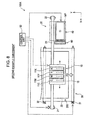
- FIG. 2B is a view that shows the ink jet printer 100 when the print head unit 10 is moved to the maintenance position MP ( FIG. 1 ) for maintenance process as viewed in the direction of arrow Y in FIG. 1 . Note that FIG. 2B does not show the components of the ink jet printer 100 other than those of the print head unit 10 and cap unit 40 for the sake of convenience.
- the cap unit 40 includes a cap body 41, an ink drain line 42, a pump 43 and a driving mechanism 45.
- the cap body 41 is a pan-shaped member that is arranged so as to be able to cover the nozzle face 15p.
- the cap body 41 is able to receive waste ink discharged from the nozzles 15 at the time of flushing.
- a through-hole 41h is provided at the bottom center of the cap body 41.
- the ink drain line 42 is connected to the through-hole 41h.
- the pump 43 is provided in the ink drain line 42.
- the pump 43 is able to vacuum waste ink accumulated in the cap body 41.
- the waste ink is guided through the ink drain line 42 to a waste ink treatment portion (not shown) for treating waste ink.
- the driving mechanism 45 raises the cap body 41 to bring the cap body 41 into close contact with the nozzle face 15p when ink is vacuumed by the pump 43. Note that at the time of flushing, the cap body 41 is maintained in a position away from the nozzle face 15p.
- FIG. 3 is a flowchart that shows the steps of bubble removal flushing according to one example embodiment of the invention.
- bubble removal flushing means a flushing operation that is intended to remove bubbles among flushing operations.
- step S10 the control unit 50 causes each of the nozzles 15 to idly discharge ink droplets 3000 successive times.
- the process of successively idly discharging ink droplets is termed as "successive flushing set".
- step S20 the control unit 50 waits for a predetermined interval (for example, about one second) and then performs the successive flushing set again in the following step S30.
- the interval is provided in step S20 in order to converge vibration of ink and vibration of the pressure chambers 13 due to the successive flushing set in the preceding process. By so doing, it is possible to effectively perform the following successive flushing set.
- a series of processes consisting of the successive flushing set and the interval is repeated predetermined selected number of times.
- FIG. 4 is a graph that shows a drive pulse 300 that the control unit 50 transmits to the piezoelectric element 17 of each nozzle 15 for discharging of a single ink droplet in the successive flushing set of the bubble removal flushing.
- the ordinate axis represents a voltage and the abscissa axis represents time.
- the drive pulse 300 is a substantially trapezoidal pulse signal and includes a first pulse portion Pwc, a second pulse portion Pwh, and a third pulse portion Pwd.
- first pulse portion Pwc a voltage value of the piezoelectric element 17 increases at a constant rate from a ground state (voltage value is 0) to Vh from time t0 to time t1.
- second pulse portion Pwh a voltage value of the piezoelectric element 17 is kept constant at Vh from time t1 to time t2.
- a voltage value of the piezoelectric element 17 returns at a constant rate from Vh to the ground state from time t2 to time t3.
- the frequency of the drive pulse 300 in the successive flushing set (frequency corresponding to a period from time t0 to time t4 shown in FIG. 4 ) is desirably 1 kHz to 5 kHz.
- FIG. 5A to FIG. 5C are schematic views that schematically show operation of the print head unit 10 on the drive pulse 300.
- FIG. 5A to FIG. 5C are enlarged views of the pressure chamber 13 of the print head unit 10 shown in FIG. 2A , and the piezoelectric element 17 and the common ink chamber 12 are not shown in the drawings.
- FIG. 5A shows a state of the pressure chamber 13 before receiving the drive pulse 300 (before time t0) .
- the pressure chamber 13 is filled with ink 400, and a bubble 500 is trapped in the ink 400. Note that the bubble 500 tends to be accumulated in a region located on the upper side in the direction of gravitational force in the pressure chamber 13 and opposite the ink flow passage 14.
- FIG. 5B shows a state of the pressure chamber 13 from time t0 to time t2 shown in FIG. 4 .
- FIG. 5C shows a state of the pressure chamber 13 from time t2 to time t3.
- a voltage value applied to the piezoelectric element 17 returns to a ground value ( FIG. 4 ), and the piezoelectric element 17 also expands to return to a normal state. That is, the diaphragm 16 returns from the bent state to a flat state.
- the ink 400 in the pressure chamber 13 is applied with a pressure from the diaphragm 16 and then discharged from the nozzle 15.
- the bubble 500 also gradually approaches to the nozzle 15 in accordance with the discharge of the ink, and is finally ejected outward from the nozzle 15.
- FIG. 5C shows locus of the bubble 500 moving toward the nozzle 15 in accordance with a large number of the drive pulses 300 being generated.
- the diameter of the bubble 500 may be increased between time t0 to time t1, and in accordance with an increase in diameter, a further large force may be applied from the diaphragm 16 to the bubble 500.
- a bubble having a micro-diameter may also be easily discharged.
- the pulse width of the first pulse portion Pwc ( FIG. 4 ) of the drive pulse 300 is desirably set to be equal to or smaller than half the Helmholtz resonance period Tc of the ink 400 in the pressure chamber 13.
- the "Helmholtz resonance period Tc" is a natural vibration period when a vibrational wave generated through increase and decrease in volume of the pressure chamber 13 propagates through the ink 400 in the pressure chamber 13, and is determined on the basis of the shapes of the pressure chamber 13, ink flow passage 14 and nozzle 15.
- FIG. 6A is a graph that shows a state of ink vibration in conformity with the Helmholtz resonance period Tc. Theoretically, it may be understood that as the pressure in the pressure chamber 13 is decreased from time t0 over a period of about half the Helmholtz resonance period Tc, vibration of ink is maximal. Then, by setting the pulse width of the first pulse portion Pwc to be equal to or smaller than half the Helmholtz resonance period Tc, a further large negative pressure may be generated in the pressure chamber 13, and the diameter of the bubble 500 may be increased.
- FIG. 6B is a table that shows the experimental results for which a discharge state is checked when bubble removal flushing is performed with different pulse widths of the first pulse portion Pwc in the print head unit having a Helmholtz resonance period Tc of 6 ⁇ s.
- the double circle in the table represents that, after bubble removal flushing, bubbles have been removed from almost all the nozzles and no dot omission is detected.
- the single circle in the table represents that, after bubble removal flushing, a bubble remains and dot omission occurs in at least one and no more than 30 percent of nozzles.
- the triangle represents that dot omission occurs in no more than 50 percent of nozzles, and the cross represents that dot omission occurs in more than 50 percent of nozzles.
- the pulse width of the first pulse portion Pwc is desirably 0.4 times or less of the Helmholtz resonance period Tc, and, particularly, is desirably one-third or less of the Helmholtz resonance period Tc or 0.3 times or less of the Helmholtz resonance period Tc.
- the pulse width is set to be equal to or smaller than half the Helmholtz resonance period Tc. This difference may be regarded that the timing at which the diameter of a bubble varies by resonating with the piezoelectric element 17 because of the natural frequency (which will be described later) of the bubble.
- the pulse width of the first pulse portion Pwc is desirably shorter the better; actually, the pulse width is more desirably set to about 1.5 ⁇ s in consideration of the response, and the like, of the piezoelectric element 17 to the drive pulse.
- FIG. 7 is a graph that shows the relationship between a diameter of a bubble and a natural frequency of the bubble. As shown in the graph, the natural frequency of the bubble decreases inversely with the diameter of the bubble. That is, an optimum contraction cycle (pulse widths of the first and second pulse portions Pwc and Pwh) of the piezoelectric element 17 for maximally increasing the diameter of the bubble varies depending on the diameter of the bubble.
- the contraction cycle of the piezoelectric element 17 is desirably set to a value according to the natural frequency of the bubble by adjusting the pulse width of the second pulse portion Pwh.
- the pulse width of the second pulse portion Pwh may be regarded as waiting time until the bubble initiates resonance.
- the pulse width of the second pulse portion Pwh is set to a different value for each successive flushing set (step S10, S30, or the like, in FIG. 3 ). More specifically, the pulse width of the second pulse portion Pwh of the drive pulse 300 generated in step S10 is set to be shorter than that generated in step S30, and subsequently, the pulse width is set to be shorter for each successive flushing set. This means that every time the successive flushing set is repeated, a removal target diameter of a bubble is reduced. By so doing, the bubble removal flushing is able to further reliably perform removal of bubbles.
- the pulse width of the third pulse portion Pwd of the drive pulse 300 ( FIG. 4 ) is desirably set to be substantially equal to the natural frequency Ta of the piezoelectric element 17. This is because the thus set pulse width of the third pulse portion Pwd suppresses an excessively continuous vibration of the piezoelectric element 17 that has received the drive pulse 300. If the piezoelectric element 17 continues vibration more than necessary, a micro-droplet of ink may be undesirably discharged from the nozzle 15 because of the vibration.
- a micro-bubble that is present in the pressure chamber 13 may also be discharged from the nozzle 15 by increasing its diameter.
- the drive pulses 300 that are intended for bubbles having different diameters are sequentially generated, it is possible to further effectively perform removal of bubbles.
- FIG. 8 is a schematic view that shows a configuration of an ink jet printer 100A according to a second example embodiment of the invention.
- FIG. 8 shows substantially the same as that of FIG. 1 except that a wiper unit 60 is provided between the paper transport unit 30 and the cap unit 40.
- FIG. 9 is a schematic view of the ink jet printer 100A when the print head unit 10 is moved to the maintenance position MP for maintenance process as viewed in the direction of arrow Y in FIG. 8 .
- FIG. 9 shows substantially the same as that of FIG. 2 except that the wiper unit 60 is added.
- the wiper unit 60 includes a wiper blade 61 that is formed of rubber or flexible resin.
- the wiper blade 61 is movable vertically by means of a driving mechanism 65.
- FIG. 10 shows a state in which the cap unit 40 hermetically seals the nozzles 15 in such a manner that the end face 41e of the cap body 41 of the cap unit 40 contacts the nozzle face 15p of the print head unit 10.
- the cap unit 40 vacuums ink from the nozzles 15 in such a manner that the pump 43 is operated in this state to apply a negative pressure in a space covered with the cap body 41 (ink vacuuming process).
- the space closed by the cap body 41 is termed as "cap closed space CS".
- FIG. 11A and FIG. 11B are schematic views that illustrate the process of wiping the nozzle face 15p by the wiper unit 60 (wiping process).
- the nozzle face 15p can be smeared with thickened ink adhered to nozzle openings.
- an ink smear may be adhered to the nozzle face 15p due to contact of the nozzle face 15p with the end face 41e of the cap body 41.
- An accumulated smear on the nozzle face 15p causes poor performance of the print head unit 10. For this reason, the nozzle face 15p is cleaned through wiping process using the wiper unit 60.
- FIG. 11A shows a state in which the distal end portion 61e of the wiper blade 61 is moved upward (indicated by arrow) to substantially the same level as that of the nozzle face 15p. Note that at this time, the cap body 41 of the cap unit 40 is not in contact with the nozzle face 15p.
- FIG. 11B shows a state in which the print head unit 10 is moved in the direction of arrow X while the wiper blade 61 is in contact with the nozzle face 15p. In this way, by moving the distal end portion 61e of the wiper blade 61 on the nozzle face 15p, it is possible to wipe off a smear on the nozzle face 15p.
- FIG. 12 is a flowchart that shows the steps of initial filling process.
- the "initial filling process” means a process in which, when at least one of the ink cartridges 11C, 11M, 11Y, and 11K mounted on the print head unit 10 is replaced, the common ink chamber 12 and the pressure chambers 13 connected to the ink cartridge are filled with ink. Note that replacement of an ink cartridge and initial filling process are performed in a state where the print head unit 10 is placed at the maintenance position MP.
- step S110 to step S120 the ink vacuuming process described with reference to FIG. 10 is performed. Through the above process, the pressure chambers 13 are filled with ink. At this time, the cap unit 40 has adhered ink that has been vacuumed from the nozzles 15.
- step S130 a negative pressure applied to the cap closed space CS ( FIG. 10 ) is released, and in step S130, the cap unit 40 is moved to an initial position to have the nozzles 15 uncovered.
- step S140 the wiping process of wiping the nozzle face using the wiper unit 60 is performed and in step S150, the pump 43 is operated to drain waste ink, adhered to the cap unit 40, through the ink drain line 42.
- first filling process the process that is performed through a series of processes from step S110 to step S150 is termed as "first filling process”.
- step S160 to step S200 the same processes as those of the first filling process are repeated (second filling process). Furthermore, in the following step S210 to step S240 as well, the same processes as those of the first and second filling processes are performed; however, the amount of vacuuming by the pump 43 at this time may be smaller than those of the previous processes.
- the filling process of step S210 to step S240 is particularly termed as "small amount filling process".
- FIG. 13 is a graph that shows a change in pressure over time in the cap closed space CS ( FIG. 10 ) in the initial filling process.
- the ink vacuuming process is performed multiple times in order to further reliably perform ink filling by reducing bubbles trapped in an ink filling region from the common ink chamber 12 to the pressure chambers 13. However, bubbles may still possibly be trapped in the pressure chambers 13.
- step S250 ( FIG. 12 ) bubble removal flushing ( FIG. 3 ) that uses the drive pulse 300 ( FIG. 4 ) described in the first example embodiment is performed.
- bubbles in the pressure chambers 13 are further reliably removed to suppress occurrence of dot omission in the nozzles 15.
- step S260 color mixture prevention flushing, which is different from the bubble removal flushing in step S250, is further performed.
- the "color mixture prevention flushing" will be described.
- the pressure in the cap closed space CS increases from a negative pressure to about atmospheric pressure.
- misty ink may return back toward the nozzle face 15p. This may cause ink, which is different in color from discharged ink, to be mixed into the nozzles 15.
- the color mixture prevention flushing is a flushing operation that discards different color ink that is mixed into the nozzles 15.
- FIG. 14 is a graph that shows a drive pulse that the control unit 50 generates for the piezoelectric elements 17 in color mixture prevention flushing.
- the drive pulse 310 which is different from the drive pulse 300 ( FIG. 4 ) in the bubble removal flushing, is to discharge a large amount of ink at a time.
- the drive pulse 310 includes a first pulse portion (from time t20 to time t21) that increases a voltage at substantially a constant rate from a ground voltage and a second pulse portion (from time t21 to time t22) that maintains a constant voltage for a predetermined period of time.
- the drive pulse 310 further includes a third pulse portion (from time t22 to time t23) that decreases a voltage at substantially a constant rate to a negative voltage, a fourth pulse portion (from time t23 to time t24) that maintains a constant negative voltage for a predetermined period of time, and a fifth pulse portion (from time t24 to time t25) that increases a voltage at substantially a constant rate to the ground voltage. That is, the drive pulse 310 includes a first substantially trapezoidal pulse 311 that generates a positive voltage and a second substantially trapezoidal pulse 312 that generates a negative voltage.
- the drive pulse 310 includes the second substantially trapezoidal pulse 312 to thereby make it possible to suppress occurrence of excessive vibration in an ink surface in the nozzle 15 and perform successive ink discharges for a short period of time.
- the control unit 50 is able to generate the drive pulse 310 multiple times in a row at a frequency of about 50 kHz (frequency corresponding to a period from time t20 to time t26).
- the bubble removal flushing (step S250) is performed before the color mixture prevention flushing (step S260 in FIG. 12 ). Because the color mixture prevention flushing is desirably performed in a state where ink droplets are discharged from all the nozzles 15, by suppressing occurrence of dot omission through the previous bubble removal flushing, it is possible to effectively perform color mixture prevention flushing.
- FIG. 15 is a schematic view that shows a configuration of an ink jet printer 100B according to a third example embodiment of the invention.
- FIG. 15 shows substantially the same as that of FIG. 8 except that an ink discharge detection unit 70 is provided for detecting discharge of ink from the nozzles 15.
- the ink discharge detection unit 70 receives an output signal from a sensor provided on the cap unit 40 and transmits a detected result to the control unit 50.
- the ink discharge detection unit 70 may be, for example, configured to electrically detect discharge of ink. Specifically, when the print head unit 10 is placed at the maintenance position MP, ink is discharged in a state where electric charge is applied between the nozzle face 15p and the cap body 41 of the cap unit 40 to thereby detect a variation in the amount of electric charge by the sensor. As the amount of ink discharged is small, a variation in the amount of electric charge is smaller than a predetermined value, so that it may be determined that dot omission is occurring in this case. Note that the ink discharge detection unit 70 may be configured to detect discharged ink droplets by an optical sensor or may be configured to perform detection through another method.
- FIG. 16 is a flowchart that shows the steps performed by the control unit 50 when printing is being performed.
- the control unit 50 when receiving print data together with print executive instruction from an external computer, or the like, in step S300, drives the print head unit 10, the head driving unit 20, and the paper transport unit 30 in accordance with the print data to thereby perform printing process in step S310.
- the control unit 50 after a predetermined time has elapsed from the initiation of printing, temporarily interrupts the printing process, moves the print head unit 10 to the maintenance position MP, and then performs nozzle checking by discharging ink droplets from all the nozzles 15 (step S320). At this time, when it is detected that normal ink droplets are discharged from all the nozzles, that is, when no dot omission is detected (step S330), the control unit 50 continues to perform printing process (step S310).
- step S330 when the ink discharge detection unit 70 detects dot omission (step S330), the control unit 50 performs bubble removal flushing (step S340). Note that the bubble removal flushing is performed as in the same manner as the process described in the first example embodiment ( FIG. 3 and FIG. 4 ).
- control unit 50 After the bubble removal flushing is performed, the control unit 50 performs nozzle checking process again (step S320) to verify performance recovery of the ink jet printer 100B. The control unit 50 repeatedly performs bubble removal flushing (step S340) until dot omission is eliminated.
- ink jet printer 100B when dot omission is detected during printing, bubble removal flushing is performed to eliminate dot omission, so that it is possible to improve print quality.
- FIG. 17 is a flowchart that shows the steps of timer cleaning process among maintenance processes performed by the ink jet printer according to one example embodiment of the invention.
- the "timer cleaning process” is a process of cleaning nozzles for recovering the performance of nozzles and is periodically performed by the control unit when the ink jet printer is not performing printing process. Note that the configuration of the ink jet printer according to the fourth example embodiment is the same as that of the ink jet printer 100B ( FIG. 15 ) of the third example embodiment.
- step S410 to step S450 shown in FIG. 17 are performed as in the same manner as those of the first filling process (step S110 to step S150) described with reference to FIG. 12 .
- the following processes of step S460 to step S490 are performed as in the same manner as those of the small amount filling process (step S210 to step S240) shown in FIG. 12 .
- vacuuming time and vacuuming amount by the pump 43 are different from those of the initial filling process shown in FIG. 12 .
- FIG. 18 is a graph that shows a change in pressure over time in the cap closed space CS in the timer cleaning process.
- FIG. 18 shows substantially the same as that of FIG. 13 except that the number of portions that indicate a negative pressure by vacuuming operation of the pump 43 is smaller by one.
- step S550 bubble removal flushing (step S550) is performed before color mixture prevention flushing (step S560).
- step S560 color mixture prevention flushing
- FIG. 19 is a schematic view that shows a configuration of an ink jet printer 100C according to a fifth example embodiment of the invention.
- FIG. 19 shows substantially the same as that of FIG. 15 except that a user operation unit 80 is provided.
- the user operation unit 80 is, for example, provided in the body of the ink jet printer 100C as a touch panel or an operating button. The user is able to issue an executive instruction of a process to the control unit 50 of the ink jet printer 100C through the user operation unit 80.
- FIG. 20 is a flowchart that shows the steps of manual cleaning process among the maintenance processes performed in the ink jet printer 100C.
- the "manual cleaning process” is a cleaning process for recovering the performance of nozzles and is performed by the control unit 50 when the user issues instruction through the user operation unit 80 when the ink jet printer 100C is not performing printing process.
- step S610 to step S650 shown in FIG. 20 the same processes as those of the first filling process (step S110 to step S150) shown in FIG. 12 are performed.
- step S660 to step S700 the same processes as those of step S610 to step S650 are repeatedly performed.
- step S710 to step S740 the same processes as those of step S610 to step S640 are performed. That is, in the manual cleaning process, ink vacuuming process is performed three successive times in a row. However, in the manual cleaning process, the amount of ink vacuumed is gradually reduced for each ink vacuuming process.
- FIG. 21 is a graph that shows a change in pressure over time near the nozzles 15 in the manual cleaning process.
- FIG. 21 shows substantially the same as that of FIG. 13 except that a negative pressure level is varied for each ink vacuuming process. In this way, by reducing the ink vacuuming amount while performing ink vacuuming process multiple times, it is possible to suppress the amount of ink used in the cleaning process while effectively performing nozzle cleaning process.
- control unit 50 After performing ink vacuuming process three times, the control unit 50 performs bubble removal flushing (step S720 to step S730) before color mixture prevention flushing as in the case of the initial filling process ( FIG. 12 ) of the second example embodiment. That is, even in the manual cleaning process as well, it is possible to suppress occurrence of dot omission through bubble removal flushing, while effectively performing color mixture prevention flushing.
- the ink jet printer 100C by performing the nozzle cleaning process in response to user's arbitrary request, it is possible to improve the print quality.
- FIG. 22 is a flowchart that shows the steps performed by the control unit when printing is performed by the ink jet printer according to one example embodiment of the invention.
- FIG. 22 shows substantially the same as those of the steps ( FIG. 16 ) performed by the control unit 50 when printing is performed as described in the third example embodiment except that step S305 and step S313 to step S315 are added.
- the configuration of the ink jet printer of the sixth example embodiment is the same as that of the ink jet printer 100B ( FIG. 15 ) of the third example embodiment.
- the control unit 50 when receiving print data together with print executive instruction from an external computer, or the like, in step S300, moves the print head unit 10 to the maintenance position MP to perform bubble removal flushing (step S305) before initiation of printing process.
- the print head unit 10 is moved again to the maintenance position MP to perform bubble removal flushing (step S315).
- bubble removal flushing is performed (step S320 to step S340).
- the ink jet printer is described; instead, the aspects of the invention may also be applied to a fluid ejecting apparatus that discharges other fluid (liquid).
- the pulse width of the second pulse portion Pwh of the drive pulse 300 ( FIG. 4 ) is set depending on the natural period of a bubble; instead, a selected pulse width may be set.
- a selected pulse width may be set.
- an ambient temperature is detected when bubble removal flushing is performed and then the pulse width of the second pulse portion Pwh is set on the basis of the detected ambient temperature.
- ink droplets are idly discharged 3000 times as successive flushing set ( FIG. 3 ); instead, ink droplets may be idly discharged selected number of times.
- the drive pulse 300 is generated continuously with the same period; instead, it may be generated with a changed period.
- the pulse width of the second pulse portion Pwh of the drive pulse 300 ( FIG. 4 ) is varied for each successive flushing set; instead, successive flushing set may be repeated with the same pulse width of the second pulse portion Pwh.
- each successive flushing set is formed of a plurality of drive pulses 300 having the same waveform; instead, the successive flushing sets may include respective drive pulses of which at least portion of waveform is different from one another.
- each successive flushing set may include, in addition to the drive pulse 300, a drive pulse 300 having a different pulse width of the second pulse portion Pwh or a drive pulse 300 having a different voltage value Vh.
- step S330 to step S340 in FIG. 16 when the ink discharge detection unit 70 detects dot omission, bubble removal flushing is performed (step S330 to step S340 in FIG. 16 ); instead, another maintenance process may be performed together with bubble removal flushing. For example, color mixture prevention flushing may be performed subsequently.
- the user operation unit 80 is provided in the body of the ink jet printer 100C; instead, it may be implemented through a program executed on an external computer connected to the ink jet printer 100C.
Abstract
Description
- The present invention relates to a maintenance method for a fluid ejecting apparatus.
- An ink jet printer performs printing by discharging (ejecting) ink droplets from nozzles toward a sheet face.
In the ink jet printer, because of thickened ink adhered to nozzle openings due to natural evaporation or absorption of pressure change in ink chambers by bubbles trapped in the ink chambers that are filled with ink, poor discharge of ink droplets may occur. - In order to keep favorable discharge of ink droplets, various techniques for a maintenance process have been suggested, which is, for example, described in
JP-A-2007-136989 JP-A-59-131464 JP-A-2007-136989 - However, even when the above maintenance process has been performed, a sufficient force, such as pressure, for draining bubbles cannot be applied for micro-diameter bubbles (for example, bubbles having a diameter of several tens µm), so that it is difficult to completely remove bubbles. The above problem not only applies to an ink jet printer but also applies to a fluid ejecting apparatus that ejects fluid other than ink (including liquid and liquid body formed of dispersed particles of a functional material). The above problem has not been addressed sufficiently.
- An advantage of some aspects of the invention is that it provides a technique for removing bubbles that cause poor ejection of nozzles in a fluid ejecting apparatus that ejects fluid.
- The invention may be implemented as the following aspects or application examples.
- A flushing method is performed in a fluid ejecting apparatus that includes a pressure chamber that is filled with fluid, a pressure generating element that is provided on a wall face of the pressure chamber and that deforms the wall face to change a pressure in the pressure chamber, and a nozzle that is in fluid communication with the pressure chamber and that is used for ejecting the fluid, wherein the flushing method idly discharges the fluid from the nozzle. The flushing method includes: repeatedly performing first flushing with a first period; and repeatedly performing second flushing with a second period. The first flushing includes: (a-1) generating a negative pressure in the pressure chamber in such a manner that the pressure generating element is driven to cause the pressure chamber to expand into an expanded state; (a-2) keeping the expanded state; and (a-3) discharging the fluid from the nozzle by causing the pressure chamber to contract from the expanded state. The second flushing includes: (b-1) generating a negative pressure in the pressure chamber in such a manner that the pressure generating element is driven to cause the pressure chamber to expand into an expanded state; (b-2) keeping the expanded state; and (b-3) discharging the fluid, the amount of which is larger than that of the first flushing, from the nozzle by causing the pressure chamber to contract from the expanded state.
- According to the above flushing method, removal of bubbles trapped in the pressure chamber may be effectively performed with a small amount of fluid discharged through the first flushing. In addition, after bubbles are removed, thickened fluid near the nozzle or fluid of different type mixed in the nozzle may be discharged through the second flushing of which the amount of discharge is large. Thus, it is possible to effectively recover the performance of a nozzle.
- In the flushing method according to the first application example, after a cartridge that contains the fluid is mounted on the fluid ejecting apparatus, a negative pressure may be applied to the nozzle to vacuum the fluid, after that a vicinity of the nozzle may be wiped off and then the first flushing and the second flushing may be performed.
- According to the above flushing method, when a cartridge is mounted, the pressure chamber may be filled with fluid, and bubbles trapped in the pressure chamber may be reliably removed.
- In the flushing method according to the first application example or second application example, the first period may be shorter than the second period.
- According to the above flushing method, bubbles may be removed with a relatively small amount of fluid discharged in the first flushing, and the amount of fluid discharged through the second flushing may be increased. Thus, it is possible to further effectively recover the performance of a nozzle.
- In the flushing method according to any one of the first application example to the third application example, time required for performing the (a-1) step may be set to be shorter than one-third of a Helmholtz resonance period of the fluid with which the pressure chamber is filled.
- According to the above flushing method, it is possible to further reliably perform removal of bubbles utilizing Helmholtz resonance.
- In the flushing method according to any one of the first application example to the fourth application example, the fluid ejecting apparatus may further include a fluid discharge detection unit that detects discharge of the fluid from the nozzle, wherein when the amount of discharged fluid detected by the fluid discharge detection unit is smaller than a predetermined value or when no fluid discharged is detected by the fluid discharge detection unit, the first flushing may be performed.
- According to the flushing method, when the fluid discharge detection unit detects that the amount of fluid discharged is reduced, the first flushing may be performed. Thus, because a maintenance process may be appropriately performed when needed, it is possible to effectively recover the performance of a nozzle.
- In the flushing method according to any one of the first application example to the fifth application example, the first flushing may be performed at a predetermined time interval and/or in response to user's instruction.
- According to the above flushing method, because the first flushing is performed periodically and/or at a selected timing through user's instruction, it is possible to reduce occurrence of potential poor discharge of a nozzle due to trapped bubbles.
- In the flushing method according to any one of the first application example to the sixth application example, the fluid ejecting apparatus may include an ink jet printer, wherein when the ink jet printer initiates printing process, the first flushing may be performed, and when a print sheet is switched to a new one during the printing process, the first flushing may be performed.
- According to the above flushing method, because the first flushing is always performed before the ink jet printer initiates printing process for each page, it is possible to suppress occurrence of poor discharge of ink nozzles, and it is possible to suppress a decrease in print quality of the ink jet printer.
- Note that the aspects of the invention may be implemented in various forms. For example, the aspects of the invention may be implemented in a form, such as a flushing method for a fluid ejecting apparatus and a fluid ejecting apparatus that implements the flushing method, a control method for a fluid ejecting apparatus and a control device for a fluid ejecting apparatus, a computer program that implements those methods or the functions of the fluid ejecting apparatuses, a recording medium that contains the computer program, and data signals that are realized in carrier waves that contain the computer program.
- The invention will be described with reference to the accompanying drawings, wherein like numbers reference like elements.
-
FIG. 1 is a schematic view that shows a configuration of an ink jet printer according to a first example embodiment. -
FIG. 2A and FIG. 2B are schematic cross-sectional views that show a configuration of a print head unit and cap unit according to the first example embodiment. -
FIG. 3 is a flowchart that shows the steps of bubble removal flushing. -
FIG. 4 is a graph that shows a drive pulse generated by a control unit in the bubble removal flushing. -
FIG. 5A to FIG. 5C are schematic views that illustrate the mechanism of removing bubbles in the bubble removal flushing. -
FIG. 6A and FIG. 6B are a graph and a table of experimental results, illustrating a desirable pulse width for a first pulse portion. -
FIG. 7 is a graph that shows the relationship between a diameter of a bubble and a natural frequency of the bubble. -
FIG. 8 is a schematic view that shows a configuration of an ink jet printer according to a second example embodiment. -
FIG. 9 is a schematic cross-sectional views that show a configuration of a print head unit, cap unit and wiper unit according to the second example embodiment. -
FIG. 10 is a schematic view that illustrates a vacuum operation in which ink is vacuumed by the cap unit. -
FIG. 11A and FIG. 11B are schematic views that illustrate a cleaning process in which a nozzle face is cleaned by the wiper unit. -
FIG. 12 is a flowchart that shows the steps of initial filling process according to the second example embodiment. -
FIG. 13 is a graph that shows a pressure change in a cap closed space when the initial filling process is being performed. -
FIG. 14 is a graph that shows a drive pulse generated by the control unit in color mixture prevention flushing. -
FIG. 15 is a schematic view that shows a configuration of an ink jet printer according to a third example embodiment. -
FIG. 16 is a flowchart that shows the steps when printing is being performed by the ink jet printer according to the third example embodiment. -
FIG. 17 is a flowchart that shows the steps of timer cleaning process according to a fourth example embodiment. -
FIG. 18 is a graph that shows a pressure change in a cap closed space when the timer cleaning process is being performed. -
FIG. 19 is a schematic view that shows a configuration of an ink jet printer according to a fifth example embodiment. -
FIG. 20 is a flowchart that shows the steps of manual cleaning process. -
FIG. 21 is a graph that shows a pressure change in a cap closed space when the manual cleaning process is being performed. -
FIG. 22 is a flowchart that shows the steps when printing is being performed by an ink jet printer according to a sixth example embodiment. - Hereinafter, an embodiment of the invention will be described on the basis of example embodiments in the following order.
- A. First Example Embodiment
- B. Second Example Embodiment
- C. Third Example Embodiment
- D. Fourth Example Embodiment
- E. Fifth Example Embodiment
- F. Sixth Example Embodiment
- G. Alternative Example Embodiments
-
FIG. 1 is a schematic view that shows a configuration of an ink jet printer according to one example embodiment of the invention. Theink jet printer 100 is an ink jet printing apparatus that forms an image by discharging ink droplets of a plurality of colors onto a sheet face in accordance with print data transmitted externally. Theink jet printer 100 includes aprint head unit 10, ahead driving unit 20, apaper transport unit 30, acap unit 40, and acontrol unit 50. - The
print head unit 10 has detachably mountedink cartridges ink jet printer 100 performs printing, theprint head unit 10 repeats reciprocal movement in a vertical direction (direction of arrow X) with respect to a transport direction PD of aprint sheet 200 while discharging ink droplets of respective colors toward the paper face. Note that the number of colors of ink cartridges mounted on theprint head unit 10 is not limited to four; it may be selected number, such as one or six. - The
head driving unit 20 includes afirst pulley 21, asecond pulley 22 and ahead driving belt 23. The twopulleys paper transport unit 30, and thehead driving belt 23 is looped around the twopulleys first pulley 21 is driven for rotation by a motor (not shown) that is controlled by thecontrol unit 50. Thesecond pulley 22 rotates following the first pulley through thehead driving belt 23. Theprint head unit 10 is fixed to thehead driving belt 23. This allows theprint head unit 10 to reciprocally move over a print face of theprint sheet 200 in accordance with rotation of thefirst pulley 21. - The
paper transport unit 30 includes a firstpaper transport roller 31, a secondpaper transport roller 32 and apaper transport belt 33 that is looped around the twopaper transport rollers paper transport roller 31 is driven for rotation by a motor (not shown) that is controlled by thecontrol unit 50. The secondpaper transport roller 32 rotates following the firstpaper transport roller 31 through thepaper transport belt 33. By so doing, theprint sheet 200 is transported on thepaper transport belt 33 in the transport direction PD during printing. - The
cap unit 40 is arranged in parallel with thepaper transport unit 30 within a region in which theprint head unit 10 is movable. Theprint head unit 10, when performing a maintenance process which will be described later, moves to a region, in which thecap unit 40 is arranged, so thatnozzles 15 provided on the bottom face (face opposite the sheet 200) of theprint head unit 10 can be sealed by thecap unit 40. The position of theprint head unit 10 at this time is termed as "maintenance position MP". Note that the details of thecap unit 40 will be described later. - The
control unit 50 is formed of a logical circuit that mainly includes a microcomputer, and is provided with a central processing unit (not shown), a storage device (not shown), and the like. Thecontrol unit 50 is connected to the above describedprint head unit 10, and the like, through signal lines and controls operation of theink jet printer 100. -
FIG. 2A is a schematic cross-sectional view that shows an internal structure of a discharge mechanism of theprint head unit 10 for discharging ink droplets.FIG. 2A shows a vicinity of anozzle 15 of theprint head unit 10 as viewed in the direction of arrow Y shown inFIG. 1 . Theprint head unit 10 includes acommon ink chamber 12 andpressure chambers 13, which are internal spaces that are filled with ink for each ink color. - Any one of the
ink cartridges common ink chamber 12, and ink flows from the ink cartridge into thecommon ink chamber 12. Thecommon ink chamber 12 is in fluid communication with thepressure chambers 13 through respectiveink flow passages 14. Ink filled in thecommon ink chamber 12 flows into and out of thepressure chambers 13 through theink flow passages 14. That is, thecommon ink chamber 12 serves as an ink buffer region for thepressure chambers 13. - A plurality of the
nozzles 15 for discharging ink are provided at the bottom faces of thepressure chambers 13 so as to be arranged in parallel with one another in the sheet transport direction (direction of arrow Y). Hereinafter, the bottom face of theprint head unit 10 is termed as "nozzle face 15p". Eachnozzle 15 is formed to be a micro-through-hole that gradually tapers from thepressure chamber 13 toward thenozzle face 15p. - A
diaphragm 16 and apiezoelectric element 17 are provided opposite eachnozzle 15 in thepressure chamber 13. Thediaphragm 16 is a plate-like member that has a thick portion that is in contact with thepiezoelectric element 17 and an elastic thin portion provided around the thick portion. The thick portion vibrates in accordance with expansion and contraction of thepiezoelectric element 17. Note that the thick portion and thin portion of thediaphragm 16 are not partitioned in the drawing. - The
piezoelectric element 17 is a laminated piezoelectric vibrator that is formed by alternately laminating a piezoelectric body and an internal electrode, and is a longitudinal vibration mode piezoelectric vibrator that is able to expand and contract in a longitudinal direction (indicated by arrow) perpendicular to a laminated direction in accordance with a voltage applied. Eachpiezoelectric element 17 is fixed to a fixedbase 18. The fixedbase 18 is formed of a sufficiently rigid member that is able to efficiently transmit vibration of thepiezoelectric element 17 to thediaphragm 16. With the above configuration, eachpiezoelectric element 17 applies a pressure to ink, with which thepressure chamber 13 is filled, through thediaphragm 16 to thereby cause ink to discharge from thenozzle 15. - Incidentally, bubbles may be trapped in ink in the
pressure chamber 13 when ink is initially filled from an ink cartridge or when printing process is continued. The bubbles absorb a pressure change in thepressure chamber 13 applied by thepiezoelectric element 17. This may produce so-called dot omission, that is, ink droplets are not appropriately discharged from a portion of nozzles. In addition, ink may clog in anozzle 15 because of thickened ink adhered to thenozzle 15 due to natural evaporation to cause nozzle clogging. For the above reasons, theink jet printer 100 performs, other than when printing process is performed, various maintenance processes in order to appropriately discharge ink droplets from the nozzles. - The maintenance processes, for example, include so-called flushing in which ink is idly discharged from the
nozzles 15 to eject bubbles or thickened ink from thenozzles 15 together with ink droplets. Here, the "idle discharge" means discharging of ink droplets, which is performed for the purpose other than the intended purpose (that is, printing). -
FIG. 2B is a view that shows theink jet printer 100 when theprint head unit 10 is moved to the maintenance position MP (FIG. 1 ) for maintenance process as viewed in the direction of arrow Y inFIG. 1 . Note thatFIG. 2B does not show the components of theink jet printer 100 other than those of theprint head unit 10 andcap unit 40 for the sake of convenience. - The
cap unit 40 includes acap body 41, anink drain line 42, apump 43 and adriving mechanism 45. Thecap body 41 is a pan-shaped member that is arranged so as to be able to cover thenozzle face 15p. Thecap body 41 is able to receive waste ink discharged from thenozzles 15 at the time of flushing. - A through-
hole 41h is provided at the bottom center of thecap body 41. Theink drain line 42 is connected to the through-hole 41h. Thepump 43 is provided in theink drain line 42. Thepump 43 is able to vacuum waste ink accumulated in thecap body 41. The waste ink is guided through theink drain line 42 to a waste ink treatment portion (not shown) for treating waste ink. Thedriving mechanism 45 raises thecap body 41 to bring thecap body 41 into close contact with thenozzle face 15p when ink is vacuumed by thepump 43. Note that at the time of flushing, thecap body 41 is maintained in a position away from thenozzle face 15p. -
FIG. 3 is a flowchart that shows the steps of bubble removal flushing according to one example embodiment of the invention. Here, the "bubble removal flushing" means a flushing operation that is intended to remove bubbles among flushing operations. - In step S10, the
control unit 50 causes each of thenozzles 15 to idly discharge ink droplets 3000 successive times. Hereinafter, the process of successively idly discharging ink droplets is termed as "successive flushing set". In step S20, thecontrol unit 50 waits for a predetermined interval (for example, about one second) and then performs the successive flushing set again in the following step S30. Here, the interval is provided in step S20 in order to converge vibration of ink and vibration of thepressure chambers 13 due to the successive flushing set in the preceding process. By so doing, it is possible to effectively perform the following successive flushing set. Hereinafter, in the bubble removal flushing, a series of processes consisting of the successive flushing set and the interval is repeated predetermined selected number of times. -
FIG. 4 is a graph that shows adrive pulse 300 that thecontrol unit 50 transmits to thepiezoelectric element 17 of eachnozzle 15 for discharging of a single ink droplet in the successive flushing set of the bubble removal flushing. The ordinate axis represents a voltage and the abscissa axis represents time. - The
drive pulse 300 is a substantially trapezoidal pulse signal and includes a first pulse portion Pwc, a second pulse portion Pwh, and a third pulse portion Pwd. In the first pulse portion Pwc, a voltage value of thepiezoelectric element 17 increases at a constant rate from a ground state (voltage value is 0) to Vh from time t0 to time t1. In the second pulse portion Pwh, a voltage value of thepiezoelectric element 17 is kept constant at Vh from time t1 to time t2. In the third pulse portion Pwd, a voltage value of thepiezoelectric element 17 returns at a constant rate from Vh to the ground state from time t2 to time t3. - Note that the frequency of the
drive pulse 300 in the successive flushing set (frequency corresponding to a period from time t0 to time t4 shown inFIG. 4 ) is desirably 1 kHz to 5 kHz. -
FIG. 5A to FIG. 5C are schematic views that schematically show operation of theprint head unit 10 on thedrive pulse 300.FIG. 5A to FIG. 5C are enlarged views of thepressure chamber 13 of theprint head unit 10 shown inFIG. 2A , and thepiezoelectric element 17 and thecommon ink chamber 12 are not shown in the drawings. -
FIG. 5A shows a state of thepressure chamber 13 before receiving the drive pulse 300 (before time t0) . Thepressure chamber 13 is filled withink 400, and abubble 500 is trapped in theink 400. Note that thebubble 500 tends to be accumulated in a region located on the upper side in the direction of gravitational force in thepressure chamber 13 and opposite theink flow passage 14. -
FIG. 5B shows a state of thepressure chamber 13 from time t0 to time t2 shown inFIG. 4 . Thepiezoelectric element 17, when receiving the first pulse portion Pwc between time t0 and time t1, contracts in accordance with an increase in applied voltage. Then, as shown inFIG. 5B , thediaphragm 16 bends outward of the pressure chamber 13 (direction of arrow), and a negative pressure is applied to theink 400 in thepressure chamber 13. Note that ameniscus 401 formed at thenozzle 15 at this time increases the degree of bending in the same direction as that of thediaphragm 16. Then, thediaphragm 16 is kept bent from time t1 to time t2. Between time t0 and time t2, the diameter of thebubble 500 increases with a decrease in pressure in thepressure chamber 13. -
FIG. 5C shows a state of thepressure chamber 13 from time t2 to time t3. Owing to the third pulse portion Pwd of thedrive pulse 300, a voltage value applied to thepiezoelectric element 17 returns to a ground value (FIG. 4 ), and thepiezoelectric element 17 also expands to return to a normal state. That is, thediaphragm 16 returns from the bent state to a flat state. By so doing, theink 400 in thepressure chamber 13 is applied with a pressure from thediaphragm 16 and then discharged from thenozzle 15. At this time, thebubble 500 also gradually approaches to thenozzle 15 in accordance with the discharge of the ink, and is finally ejected outward from thenozzle 15.FIG. 5C shows locus of thebubble 500 moving toward thenozzle 15 in accordance with a large number of thedrive pulses 300 being generated. - Here, as described with reference to
FIG. 5B , according to thedrive pulse 300, the diameter of thebubble 500 may be increased between time t0 to time t1, and in accordance with an increase in diameter, a further large force may be applied from thediaphragm 16 to thebubble 500. Thus, according to thedrive pulse 300, for example, a bubble having a micro-diameter may also be easily discharged. - As can be understood from the above description, by decreasing the pressure in the
pressure chamber 13 to increase the diameter of thebubble 500 as much as possible, it is possible to further reliably discharge and remove thebubble 500. Thus, the pulse width of the first pulse portion Pwc (FIG. 4 ) of thedrive pulse 300 is desirably set to be equal to or smaller than half the Helmholtz resonance period Tc of theink 400 in thepressure chamber 13. Here, the "Helmholtz resonance period Tc" is a natural vibration period when a vibrational wave generated through increase and decrease in volume of thepressure chamber 13 propagates through theink 400 in thepressure chamber 13, and is determined on the basis of the shapes of thepressure chamber 13,ink flow passage 14 andnozzle 15. -
FIG. 6A is a graph that shows a state of ink vibration in conformity with the Helmholtz resonance period Tc. Theoretically, it may be understood that as the pressure in thepressure chamber 13 is decreased from time t0 over a period of about half the Helmholtz resonance period Tc, vibration of ink is maximal. Then, by setting the pulse width of the first pulse portion Pwc to be equal to or smaller than half the Helmholtz resonance period Tc, a further large negative pressure may be generated in thepressure chamber 13, and the diameter of thebubble 500 may be increased. -
FIG. 6B is a table that shows the experimental results for which a discharge state is checked when bubble removal flushing is performed with different pulse widths of the first pulse portion Pwc in the print head unit having a Helmholtz resonance period Tc of 6 µs. Note that the double circle in the table represents that, after bubble removal flushing, bubbles have been removed from almost all the nozzles and no dot omission is detected. The single circle in the table represents that, after bubble removal flushing, a bubble remains and dot omission occurs in at least one and no more than 30 percent of nozzles. In addition, the triangle represents that dot omission occurs in no more than 50 percent of nozzles, and the cross represents that dot omission occurs in more than 50 percent of nozzles. - As shown in the table, the pulse width of the first pulse portion Pwc is desirably 0.4 times or less of the Helmholtz resonance period Tc, and, particularly, is desirably one-third or less of the Helmholtz resonance period Tc or 0.3 times or less of the Helmholtz resonance period Tc. However, it is described with reference to
FIG. 6A that the pulse width is set to be equal to or smaller than half the Helmholtz resonance period Tc. This difference may be regarded that the timing at which the diameter of a bubble varies by resonating with thepiezoelectric element 17 because of the natural frequency (which will be described later) of the bubble. Note that the pulse width of the first pulse portion Pwc is desirably shorter the better; actually, the pulse width is more desirably set to about 1.5 µs in consideration of the response, and the like, of thepiezoelectric element 17 to the drive pulse. -
FIG. 7 is a graph that shows the relationship between a diameter of a bubble and a natural frequency of the bubble. As shown in the graph, the natural frequency of the bubble decreases inversely with the diameter of the bubble. That is, an optimum contraction cycle (pulse widths of the first and second pulse portions Pwc and Pwh) of thepiezoelectric element 17 for maximally increasing the diameter of the bubble varies depending on the diameter of the bubble. - As described above, because the pulse width of the first pulse portion Pwc is set to a value according to the Helmholtz resonance period Tc, the contraction cycle of the
piezoelectric element 17 is desirably set to a value according to the natural frequency of the bubble by adjusting the pulse width of the second pulse portion Pwh. By so doing, in the following third pulse portion Pwd, it is possible to discharge an ink droplet at the timing at which the diameter of the bubble is further increased. Note that the pulse width of the second pulse portion Pwh may be regarded as waiting time until the bubble initiates resonance. - Incidentally, in the present example embodiment, the pulse width of the second pulse portion Pwh is set to a different value for each successive flushing set (step S10, S30, or the like, in
FIG. 3 ). More specifically, the pulse width of the second pulse portion Pwh of thedrive pulse 300 generated in step S10 is set to be shorter than that generated in step S30, and subsequently, the pulse width is set to be shorter for each successive flushing set. This means that every time the successive flushing set is repeated, a removal target diameter of a bubble is reduced. By so doing, the bubble removal flushing is able to further reliably perform removal of bubbles. - Furthermore, the pulse width of the third pulse portion Pwd of the drive pulse 300 (
FIG. 4 ) is desirably set to be substantially equal to the natural frequency Ta of thepiezoelectric element 17. This is because the thus set pulse width of the third pulse portion Pwd suppresses an excessively continuous vibration of thepiezoelectric element 17 that has received thedrive pulse 300. If thepiezoelectric element 17 continues vibration more than necessary, a micro-droplet of ink may be undesirably discharged from thenozzle 15 because of the vibration. - In the
ink jet printer 100 that performs bubble removal flushing using thedrive pulse 300, a micro-bubble that is present in thepressure chamber 13 may also be discharged from thenozzle 15 by increasing its diameter. In addition, because thedrive pulses 300 that are intended for bubbles having different diameters are sequentially generated, it is possible to further effectively perform removal of bubbles. -
FIG. 8 is a schematic view that shows a configuration of anink jet printer 100A according to a second example embodiment of the invention.FIG. 8 shows substantially the same as that ofFIG. 1 except that awiper unit 60 is provided between thepaper transport unit 30 and thecap unit 40. -
FIG. 9 is a schematic view of theink jet printer 100A when theprint head unit 10 is moved to the maintenance position MP for maintenance process as viewed in the direction of arrow Y inFIG. 8 .FIG. 9 shows substantially the same as that ofFIG. 2 except that thewiper unit 60 is added. - The
wiper unit 60 includes awiper blade 61 that is formed of rubber or flexible resin. Thewiper blade 61 is movable vertically by means of adriving mechanism 65. -
FIG. 10 shows a state in which thecap unit 40 hermetically seals thenozzles 15 in such a manner that theend face 41e of thecap body 41 of thecap unit 40 contacts thenozzle face 15p of theprint head unit 10. Thecap unit 40 vacuums ink from thenozzles 15 in such a manner that thepump 43 is operated in this state to apply a negative pressure in a space covered with the cap body 41 (ink vacuuming process). Hereinafter, the space closed by thecap body 41 is termed as "cap closed space CS". -
FIG. 11A and FIG. 11B are schematic views that illustrate the process of wiping thenozzle face 15p by the wiper unit 60 (wiping process). Thenozzle face 15p can be smeared with thickened ink adhered to nozzle openings. In addition, at the time of the above ink vacuuming process, an ink smear may be adhered to thenozzle face 15p due to contact of thenozzle face 15p with theend face 41e of thecap body 41. An accumulated smear on thenozzle face 15p causes poor performance of theprint head unit 10. For this reason, thenozzle face 15p is cleaned through wiping process using thewiper unit 60. -
FIG. 11A shows a state in which thedistal end portion 61e of thewiper blade 61 is moved upward (indicated by arrow) to substantially the same level as that of thenozzle face 15p. Note that at this time, thecap body 41 of thecap unit 40 is not in contact with thenozzle face 15p.FIG. 11B shows a state in which theprint head unit 10 is moved in the direction of arrow X while thewiper blade 61 is in contact with thenozzle face 15p. In this way, by moving thedistal end portion 61e of thewiper blade 61 on thenozzle face 15p, it is possible to wipe off a smear on thenozzle face 15p. -
FIG. 12 is a flowchart that shows the steps of initial filling process. Here, the "initial filling process" means a process in which, when at least one of theink cartridges print head unit 10 is replaced, thecommon ink chamber 12 and thepressure chambers 13 connected to the ink cartridge are filled with ink. Note that replacement of an ink cartridge and initial filling process are performed in a state where theprint head unit 10 is placed at the maintenance position MP. - In step S110 to step S120, the ink vacuuming process described with reference to
FIG. 10 is performed. Through the above process, thepressure chambers 13 are filled with ink. At this time, thecap unit 40 has adhered ink that has been vacuumed from thenozzles 15. - After that, a negative pressure applied to the cap closed space CS (
FIG. 10 ) is released, and in step S130, thecap unit 40 is moved to an initial position to have thenozzles 15 uncovered. In step S140, the wiping process of wiping the nozzle face using thewiper unit 60 is performed and in step S150, thepump 43 is operated to drain waste ink, adhered to thecap unit 40, through theink drain line 42. Hereinafter, the process that is performed through a series of processes from step S110 to step S150 is termed as "first filling process". - In step S160 to step S200, the same processes as those of the first filling process are repeated (second filling process). Furthermore, in the following step S210 to step S240 as well, the same processes as those of the first and second filling processes are performed; however, the amount of vacuuming by the
pump 43 at this time may be smaller than those of the previous processes. The filling process of step S210 to step S240 is particularly termed as "small amount filling process". -
FIG. 13 is a graph that shows a change in pressure over time in the cap closed space CS (FIG. 10 ) in the initial filling process. The ink vacuuming process is performed multiple times in order to further reliably perform ink filling by reducing bubbles trapped in an ink filling region from thecommon ink chamber 12 to thepressure chambers 13. However, bubbles may still possibly be trapped in thepressure chambers 13. - For this reason, in step S250 (
FIG. 12 ), bubble removal flushing (FIG. 3 ) that uses the drive pulse 300 (FIG. 4 ) described in the first example embodiment is performed. By so doing, bubbles in thepressure chambers 13 are further reliably removed to suppress occurrence of dot omission in thenozzles 15. - In step S260, color mixture prevention flushing, which is different from the bubble removal flushing in step S250, is further performed. Here, the "color mixture prevention flushing" will be described. At the time of the above described ink vacuuming process, in some time frames Cft (
FIG. 13 ), the pressure in the cap closed space CS increases from a negative pressure to about atmospheric pressure. At this time, within the cap closed space CS (FIG. 10 ), misty ink may return back toward thenozzle face 15p. This may cause ink, which is different in color from discharged ink, to be mixed into thenozzles 15. In addition, in the wiping process, when thenozzle face 15p is wiped off by thewiper blade 61, different color ink may be mixed into thenozzles 15. The color mixture prevention flushing is a flushing operation that discards different color ink that is mixed into thenozzles 15. -
FIG. 14 is a graph that shows a drive pulse that thecontrol unit 50 generates for thepiezoelectric elements 17 in color mixture prevention flushing. Thedrive pulse 310, which is different from the drive pulse 300 (FIG. 4 ) in the bubble removal flushing, is to discharge a large amount of ink at a time. - The
drive pulse 310 includes a first pulse portion (from time t20 to time t21) that increases a voltage at substantially a constant rate from a ground voltage and a second pulse portion (from time t21 to time t22) that maintains a constant voltage for a predetermined period of time. In addition, thedrive pulse 310 further includes a third pulse portion (from time t22 to time t23) that decreases a voltage at substantially a constant rate to a negative voltage, a fourth pulse portion (from time t23 to time t24) that maintains a constant negative voltage for a predetermined period of time, and a fifth pulse portion (from time t24 to time t25) that increases a voltage at substantially a constant rate to the ground voltage. That is, thedrive pulse 310 includes a first substantiallytrapezoidal pulse 311 that generates a positive voltage and a second substantiallytrapezoidal pulse 312 that generates a negative voltage. - The
drive pulse 310 includes the second substantiallytrapezoidal pulse 312 to thereby make it possible to suppress occurrence of excessive vibration in an ink surface in thenozzle 15 and perform successive ink discharges for a short period of time. For example, in the color mixture prevention flushing, thecontrol unit 50 is able to generate thedrive pulse 310 multiple times in a row at a frequency of about 50 kHz (frequency corresponding to a period from time t20 to time t26). - In this way, in the initial filling process, the bubble removal flushing (step S250) is performed before the color mixture prevention flushing (step S260 in
FIG. 12 ). Because the color mixture prevention flushing is desirably performed in a state where ink droplets are discharged from all thenozzles 15, by suppressing occurrence of dot omission through the previous bubble removal flushing, it is possible to effectively perform color mixture prevention flushing. -
FIG. 15 is a schematic view that shows a configuration of anink jet printer 100B according to a third example embodiment of the invention.FIG. 15 shows substantially the same as that ofFIG. 8 except that an inkdischarge detection unit 70 is provided for detecting discharge of ink from thenozzles 15. The inkdischarge detection unit 70 receives an output signal from a sensor provided on thecap unit 40 and transmits a detected result to thecontrol unit 50. - The ink
discharge detection unit 70 may be, for example, configured to electrically detect discharge of ink. Specifically, when theprint head unit 10 is placed at the maintenance position MP, ink is discharged in a state where electric charge is applied between thenozzle face 15p and thecap body 41 of thecap unit 40 to thereby detect a variation in the amount of electric charge by the sensor. As the amount of ink discharged is small, a variation in the amount of electric charge is smaller than a predetermined value, so that it may be determined that dot omission is occurring in this case. Note that the inkdischarge detection unit 70 may be configured to detect discharged ink droplets by an optical sensor or may be configured to perform detection through another method. -
FIG. 16 is a flowchart that shows the steps performed by thecontrol unit 50 when printing is being performed. Thecontrol unit 50, when receiving print data together with print executive instruction from an external computer, or the like, in step S300, drives theprint head unit 10, thehead driving unit 20, and thepaper transport unit 30 in accordance with the print data to thereby perform printing process in step S310. - The
control unit 50, after a predetermined time has elapsed from the initiation of printing, temporarily interrupts the printing process, moves theprint head unit 10 to the maintenance position MP, and then performs nozzle checking by discharging ink droplets from all the nozzles 15 (step S320). At this time, when it is detected that normal ink droplets are discharged from all the nozzles, that is, when no dot omission is detected (step S330), thecontrol unit 50 continues to perform printing process (step S310). - On the other hand, in step S330, when the ink
discharge detection unit 70 detects dot omission (step S330), thecontrol unit 50 performs bubble removal flushing (step S340). Note that the bubble removal flushing is performed as in the same manner as the process described in the first example embodiment (FIG. 3 and FIG. 4 ). - After the bubble removal flushing is performed, the
control unit 50 performs nozzle checking process again (step S320) to verify performance recovery of theink jet printer 100B. Thecontrol unit 50 repeatedly performs bubble removal flushing (step S340) until dot omission is eliminated. - According to the
ink jet printer 100B, when dot omission is detected during printing, bubble removal flushing is performed to eliminate dot omission, so that it is possible to improve print quality. -
FIG. 17 is a flowchart that shows the steps of timer cleaning process among maintenance processes performed by the ink jet printer according to one example embodiment of the invention. The "timer cleaning process" is a process of cleaning nozzles for recovering the performance of nozzles and is periodically performed by the control unit when the ink jet printer is not performing printing process. Note that the configuration of the ink jet printer according to the fourth example embodiment is the same as that of theink jet printer 100B (FIG. 15 ) of the third example embodiment. - The processes of step S410 to step S450 shown in
FIG. 17 are performed as in the same manner as those of the first filling process (step S110 to step S150) described with reference toFIG. 12 . In addition, the following processes of step S460 to step S490 are performed as in the same manner as those of the small amount filling process (step S210 to step S240) shown inFIG. 12 . However, vacuuming time and vacuuming amount by thepump 43 are different from those of the initial filling process shown inFIG. 12 . -
FIG. 18 is a graph that shows a change in pressure over time in the cap closed space CS in the timer cleaning process.FIG. 18 shows substantially the same as that ofFIG. 13 except that the number of portions that indicate a negative pressure by vacuuming operation of thepump 43 is smaller by one. - Note that in the timer cleaning process as well, as in the case of the initial filling process of the second example embodiment, bubble removal flushing (step S550) is performed before color mixture prevention flushing (step S560). Thus, as in the case of the second example embodiment, it is possible to effectively perform color mixture prevention flushing.
- In this way, by performing the timer cleaning process of the fourth example embodiment, it is possible to suppress dot omission and ink clogging of the
nozzles 15 to thereby improve the print quality of the ink jet printer. -
FIG. 19 is a schematic view that shows a configuration of anink jet printer 100C according to a fifth example embodiment of the invention.FIG. 19 shows substantially the same as that ofFIG. 15 except that auser operation unit 80 is provided. - The
user operation unit 80 is, for example, provided in the body of theink jet printer 100C as a touch panel or an operating button. The user is able to issue an executive instruction of a process to thecontrol unit 50 of theink jet printer 100C through theuser operation unit 80. -
FIG. 20 is a flowchart that shows the steps of manual cleaning process among the maintenance processes performed in theink jet printer 100C. The "manual cleaning process" is a cleaning process for recovering the performance of nozzles and is performed by thecontrol unit 50 when the user issues instruction through theuser operation unit 80 when theink jet printer 100C is not performing printing process. - In step S610 to step S650 shown in
FIG. 20 , the same processes as those of the first filling process (step S110 to step S150) shown inFIG. 12 are performed. In the following step S660 to step S700, the same processes as those of step S610 to step S650 are repeatedly performed. In step S710 to step S740, the same processes as those of step S610 to step S640 are performed. That is, in the manual cleaning process, ink vacuuming process is performed three successive times in a row. However, in the manual cleaning process, the amount of ink vacuumed is gradually reduced for each ink vacuuming process. -
FIG. 21 is a graph that shows a change in pressure over time near thenozzles 15 in the manual cleaning process.FIG. 21 shows substantially the same as that ofFIG. 13 except that a negative pressure level is varied for each ink vacuuming process. In this way, by reducing the ink vacuuming amount while performing ink vacuuming process multiple times, it is possible to suppress the amount of ink used in the cleaning process while effectively performing nozzle cleaning process. - After performing ink vacuuming process three times, the
control unit 50 performs bubble removal flushing (step S720 to step S730) before color mixture prevention flushing as in the case of the initial filling process (FIG. 12 ) of the second example embodiment. That is, even in the manual cleaning process as well, it is possible to suppress occurrence of dot omission through bubble removal flushing, while effectively performing color mixture prevention flushing. - According to the
ink jet printer 100C, by performing the nozzle cleaning process in response to user's arbitrary request, it is possible to improve the print quality. -
FIG. 22 is a flowchart that shows the steps performed by the control unit when printing is performed by the ink jet printer according to one example embodiment of the invention.FIG. 22 shows substantially the same as those of the steps (FIG. 16 ) performed by thecontrol unit 50 when printing is performed as described in the third example embodiment except that step S305 and step S313 to step S315 are added. Note that the configuration of the ink jet printer of the sixth example embodiment is the same as that of theink jet printer 100B (FIG. 15 ) of the third example embodiment. - The
control unit 50, when receiving print data together with print executive instruction from an external computer, or the like, in step S300, moves theprint head unit 10 to the maintenance position MP to perform bubble removal flushing (step S305) before initiation of printing process. In addition, during printing, when page feed is performed for continuously performing printing on a new sheet (step S313), theprint head unit 10 is moved again to the maintenance position MP to perform bubble removal flushing (step S315). Furthermore, as in the case of the third example embodiment, when the inkdischarge detection unit 70 detects dot omission, bubble removal flushing is performed (step S320 to step S340). - According to the steps when printing is performed, because bubble removal flushing is definitely performed at a predetermined timing, it is possible to reduce occurrence of potential dot omission and furthermore it is possible to improve print quality.
- Note that the aspects of the invention are not limited to the example embodiments or embodiment described above, but they may be modified into various alternative example embodiments without departing from the scope of the appended claims. The following alternative example embodiments are, for example, applicable.
- In the above example embodiments, the ink jet printer is described; instead, the aspects of the invention may also be applied to a fluid ejecting apparatus that discharges other fluid (liquid).
- In the above example embodiments, the pulse width of the second pulse portion Pwh of the drive pulse 300 (
FIG. 4 ) is set depending on the natural period of a bubble; instead, a selected pulse width may be set. In addition, it is applicable that an ambient temperature is detected when bubble removal flushing is performed and then the pulse width of the second pulse portion Pwh is set on the basis of the detected ambient temperature. - In the above example embodiments, ink droplets are idly discharged 3000 times as successive flushing set (
FIG. 3 ); instead, ink droplets may be idly discharged selected number of times. In addition, in each successive flushing set, thedrive pulse 300 is generated continuously with the same period; instead, it may be generated with a changed period. - In the above example embodiments, the pulse width of the second pulse portion Pwh of the drive pulse 300 (
FIG. 4 ) is varied for each successive flushing set; instead, successive flushing set may be repeated with the same pulse width of the second pulse portion Pwh. - In the above example embodiments, each successive flushing set is formed of a plurality of
drive pulses 300 having the same waveform; instead, the successive flushing sets may include respective drive pulses of which at least portion of waveform is different from one another. For example, each successive flushing set may include, in addition to thedrive pulse 300, adrive pulse 300 having a different pulse width of the second pulse portion Pwh or adrive pulse 300 having a different voltage value Vh. - In the above third example embodiment, when the ink
discharge detection unit 70 detects dot omission, bubble removal flushing is performed (step S330 to step S340 inFIG. 16 ); instead, another maintenance process may be performed together with bubble removal flushing. For example, color mixture prevention flushing may be performed subsequently. G7. Seventh Alternative Example Embodiment - In the fifth example embodiment, the
user operation unit 80 is provided in the body of theink jet printer 100C; instead, it may be implemented through a program executed on an external computer connected to theink jet printer 100C.
Claims (7)
- A flushing method that is performed in a fluid ejecting apparatus that includes a pressure chamber that is filled with fluid, a pressure generating element that is provided over a wall face of the pressure chamber and that deforms the wall face to change a pressure in the pressure chamber, and a nozzle that is in fluid communication with the pressure chamber and that is used for ejecting the fluid, wherein the flushing method idly discharges the fluid from the nozzle, the flushing method comprising:repeatedly performing first flushing with a first period, wherein the first flushing includes:(a-1) generating a negative pressure in the pressure chamber in such a manner that the pressure generating element is driven to cause the pressure chamber to expand into an expanded state;(a-2) keeping the expanded state; and(a-3) discharging the fluid from the nozzle by causing the pressure chamber to contract from the expanded state; andrepeatedly performing second flushing with a second period, wherein the second flushing includes:(b-1) generating a negative pressure in the pressure chamber in such a manner that the pressure generating element is driven to cause the pressure chamber to expand into an expanded state;(b-2) keeping the expanded state; and(b-3) discharging the fluid, the amount of which is larger than that of the first flushing, from the nozzle by causing the pressure chamber to contract from the expanded state.
- The flushing method according to Claim 1, wherein after a cartridge that contains the fluid is mounted on the fluid ejecting apparatus, a negative pressure is applied to the nozzle to vacuum the fluid, after that a vicinity of the nozzle is wiped off, and then the first flushing and the second flushing are performed.
- The flushing method according to Claim 1 or 2, wherein the first period is shorter than the second period.
- The flushing method according to any of the preceding claims, wherein time required for performing the (a-1) step is set to be shorter than one-third of a Helmholtz resonance period of the fluid with which the pressure chamber is filled.
- The flushing method according to any of the preceding claims, wherein
the fluid ejecting apparatus further includes a fluid discharge detection unit that detects discharge of the fluid from the nozzle, and wherein
when the amount of discharged fluid detected by the fluid discharge detection unit is smaller than a predetermined value or when no fluid discharged is detected by the fluid discharge detection unit, the first flushing is performed. - The flushing method according to any of the preceding claims, wherein the first flushing is performed at a predetermined time interval and/or in response to user's instruction.
- The flushing method according to any of the preceding claims, wherein
the fluid ejecting apparatus includes an ink jet printer, and wherein
when the ink jet printer initiates printing process, the first flushing is performed, and when a print sheet is switched to a new one during the printing process, the first flushing is performed.
Applications Claiming Priority (1)
| Application Number | Priority Date | Filing Date | Title |
|---|---|---|---|
| JP2007244956A JP5223277B2 (en) | 2007-09-21 | 2007-09-21 | Flushing method for fluid ejection device |
Publications (3)
| Publication Number | Publication Date |
|---|---|
| EP2039518A2 true EP2039518A2 (en) | 2009-03-25 |
| EP2039518A3 EP2039518A3 (en) | 2009-12-30 |
| EP2039518B1 EP2039518B1 (en) | 2012-06-27 |
Family
ID=40158325
Family Applications (1)
| Application Number | Title | Priority Date | Filing Date |
|---|---|---|---|
| EP08016439A Active EP2039518B1 (en) | 2007-09-21 | 2008-09-18 | Flushing method for fluid ejecting apparatus |
Country Status (3)
| Country | Link |
|---|---|
| US (1) | US8727489B2 (en) |
| EP (1) | EP2039518B1 (en) |
| JP (1) | JP5223277B2 (en) |
Cited By (1)
| Publication number | Priority date | Publication date | Assignee | Title |
|---|---|---|---|---|
| EP2399749A4 (en) * | 2009-02-19 | 2016-12-28 | Mimaki Eng Co Ltd | Printer device and method of maintaining same |
Families Citing this family (9)
| Publication number | Priority date | Publication date | Assignee | Title |
|---|---|---|---|---|
| JP5211859B2 (en) * | 2008-05-30 | 2013-06-12 | セイコーエプソン株式会社 | Fluid ejection device |
| JP5239931B2 (en) * | 2008-05-30 | 2013-07-17 | セイコーエプソン株式会社 | Fluid ejection device |
| JP5304548B2 (en) | 2009-08-31 | 2013-10-02 | ブラザー工業株式会社 | Liquid ejection device |
| JP6051978B2 (en) * | 2013-03-14 | 2016-12-27 | セイコーエプソン株式会社 | Printing apparatus and nozzle inspection method |
| JP2015223762A (en) | 2014-05-28 | 2015-12-14 | セイコーエプソン株式会社 | Liquid injection device, control method of liquid injection head and control method of liquid injection device |
| JP2015229343A (en) * | 2014-06-09 | 2015-12-21 | セイコーエプソン株式会社 | Liquid injection device, control method of liquid injection head, control method of liquid injection device |
| JP2016000475A (en) | 2014-06-11 | 2016-01-07 | セイコーエプソン株式会社 | Liquid jet device, control method of liquid jet head, and control method of the liquid jet device |
| JP7310374B2 (en) * | 2019-07-03 | 2023-07-19 | セイコーエプソン株式会社 | Three-dimensional object manufacturing equipment |
| JP2022037409A (en) * | 2020-08-25 | 2022-03-09 | セイコーエプソン株式会社 | Liquid injection device, and liquid injection device maintenance method |
Citations (2)
| Publication number | Priority date | Publication date | Assignee | Title |
|---|---|---|---|---|
| JPS59131464A (en) | 1983-01-17 | 1984-07-28 | Seiko Epson Corp | Clogging preventing apparatus |
| JP2007136989A (en) | 2005-11-22 | 2007-06-07 | Ricoh Co Ltd | Image forming device |
Family Cites Families (7)
| Publication number | Priority date | Publication date | Assignee | Title |
|---|---|---|---|---|
| DE69735214T2 (en) * | 1996-04-10 | 2006-10-19 | Seiko Epson Corp. | A method of operating an ink jet recording head |
| DE60229093D1 (en) * | 2001-08-29 | 2008-11-13 | Seiko Epson Corp | A liquid jet device and method of controlling the same |
| JP2004034607A (en) * | 2002-07-05 | 2004-02-05 | Seiko Epson Corp | Liquid jet apparatus and driving method of the apparatus |
| US20040034607A1 (en) * | 2002-08-13 | 2004-02-19 | Giacomo Piccinelli | Validating communication between participants in an electronic interaction |
| JP2005262551A (en) * | 2004-03-17 | 2005-09-29 | Seiko Epson Corp | Liquid jet apparatus and its control method |
| US7267422B2 (en) * | 2004-06-07 | 2007-09-11 | Hewlett-Packard Development Company, L.P. | Purging fixing-liquid ejection devices |
| EP1616704A3 (en) * | 2004-07-16 | 2006-03-22 | Agfa-Gevaert | Method and apparatus to create a waiveform for driving a printhead |
-
2007
- 2007-09-21 JP JP2007244956A patent/JP5223277B2/en active Active
-
2008
- 2008-09-18 EP EP08016439A patent/EP2039518B1/en active Active
- 2008-09-19 US US12/234,254 patent/US8727489B2/en active Active
Patent Citations (2)
| Publication number | Priority date | Publication date | Assignee | Title |
|---|---|---|---|---|
| JPS59131464A (en) | 1983-01-17 | 1984-07-28 | Seiko Epson Corp | Clogging preventing apparatus |
| JP2007136989A (en) | 2005-11-22 | 2007-06-07 | Ricoh Co Ltd | Image forming device |
Cited By (1)
| Publication number | Priority date | Publication date | Assignee | Title |
|---|---|---|---|---|
| EP2399749A4 (en) * | 2009-02-19 | 2016-12-28 | Mimaki Eng Co Ltd | Printer device and method of maintaining same |
Also Published As
| Publication number | Publication date |
|---|---|
| US8727489B2 (en) | 2014-05-20 |
| US20090079788A1 (en) | 2009-03-26 |
| EP2039518A3 (en) | 2009-12-30 |
| JP5223277B2 (en) | 2013-06-26 |
| EP2039518B1 (en) | 2012-06-27 |
| JP2009073076A (en) | 2009-04-09 |
Similar Documents
| Publication | Publication Date | Title |
|---|---|---|
| EP2039515A1 (en) | Fluid ejecting apparatus | |
| EP2039518B1 (en) | Flushing method for fluid ejecting apparatus | |
| EP2127882B1 (en) | Fluid ejecting apparatus | |
| US20090295854A1 (en) | Fluid ejecting apparatus | |
| US6672704B2 (en) | Liquid ejecting apparatus and method of cleaning an ejection head | |
| US6802589B2 (en) | Liquid-jetting apparatus and method of driving the same | |
| JP2007160819A (en) | Liquid droplet discharge device | |
| JP3679865B2 (en) | Inkjet recording device | |
| US7967411B2 (en) | Liquid ejecting apparatus, wiping method of liquid ejecting head, and printing apparatus | |
| JP3695502B2 (en) | Ink jet recording apparatus and recording head cleaning control method in the same | |
| JP2001026123A (en) | Ink jet recorder | |
| JP2004042314A (en) | Liquid ejector and its flushing method | |
| JP4506427B2 (en) | Liquid ejector | |
| JP5776708B2 (en) | Fluid ejection device | |
| JP5211860B2 (en) | Fluid ejection device | |
| JPH10278302A (en) | Ink jet recorder | |
| JP2003266670A (en) | Liquid ejector | |
| JP4415398B2 (en) | Ink jet recording apparatus control method and ink jet recording apparatus | |
| EP1944166B1 (en) | Image forming apparatus | |
| JP4383724B2 (en) | Inkjet recording device | |
| JP2004155043A (en) | Liquid injection device, control device, and method for coating moisture holding agent | |
| JP2014024210A (en) | Inkjet recording apparatus and method for controlling the same | |
| JP2024017539A (en) | inkjet recording device | |
| JP2001105629A (en) | Ink jet recording apparatus and cleaning control method of recording head therein | |
| JP2006137158A (en) | Liquid jet device |
Legal Events
| Date | Code | Title | Description |
|---|---|---|---|
| PUAI | Public reference made under article 153(3) epc to a published international application that has entered the european phase |
Free format text: ORIGINAL CODE: 0009012 |
|
| AK | Designated contracting states |
Kind code of ref document: A2 Designated state(s): AT BE BG CH CY CZ DE DK EE ES FI FR GB GR HR HU IE IS IT LI LT LU LV MC MT NL NO PL PT RO SE SI SK TR |
|
| AX | Request for extension of the european patent |
Extension state: AL BA MK RS |
|
| PUAL | Search report despatched |
Free format text: ORIGINAL CODE: 0009013 |
|
| AK | Designated contracting states |
Kind code of ref document: A3 Designated state(s): AT BE BG CH CY CZ DE DK EE ES FI FR GB GR HR HU IE IS IT LI LT LU LV MC MT NL NO PL PT RO SE SI SK TR |
|
| AX | Request for extension of the european patent |
Extension state: AL BA MK RS |
|
| RIC1 | Information provided on ipc code assigned before grant |
Ipc: B41J 2/165 20060101AFI20090113BHEP Ipc: B41J 2/045 20060101ALI20091124BHEP |
|
| 17P | Request for examination filed |
Effective date: 20100601 |
|
| AKX | Designation fees paid |
Designated state(s): DE FR GB |
|
| 17Q | First examination report despatched |
Effective date: 20110523 |
|
| GRAP | Despatch of communication of intention to grant a patent |
Free format text: ORIGINAL CODE: EPIDOSNIGR1 |
|
| GRAS | Grant fee paid |
Free format text: ORIGINAL CODE: EPIDOSNIGR3 |
|
| GRAA | (expected) grant |
Free format text: ORIGINAL CODE: 0009210 |
|
| AK | Designated contracting states |
Kind code of ref document: B1 Designated state(s): DE FR GB |
|
| REG | Reference to a national code |
Ref country code: GB Ref legal event code: FG4D |
|
| REG | Reference to a national code |
Ref country code: DE Ref legal event code: R096 Ref document number: 602008016646 Country of ref document: DE Effective date: 20120823 |
|
| PLBE | No opposition filed within time limit |
Free format text: ORIGINAL CODE: 0009261 |
|
| STAA | Information on the status of an ep patent application or granted ep patent |
Free format text: STATUS: NO OPPOSITION FILED WITHIN TIME LIMIT |
|
| 26N | No opposition filed |
Effective date: 20130328 |
|
| REG | Reference to a national code |
Ref country code: DE Ref legal event code: R097 Ref document number: 602008016646 Country of ref document: DE Effective date: 20130328 |
|
| REG | Reference to a national code |
Ref country code: FR Ref legal event code: PLFP Year of fee payment: 9 |
|
| REG | Reference to a national code |
Ref country code: FR Ref legal event code: PLFP Year of fee payment: 10 |
|
| REG | Reference to a national code |
Ref country code: FR Ref legal event code: PLFP Year of fee payment: 11 |
|
| PGFP | Annual fee paid to national office [announced via postgrant information from national office to epo] |
Ref country code: GB Payment date: 20230727 Year of fee payment: 16 |
|
| PGFP | Annual fee paid to national office [announced via postgrant information from national office to epo] |
Ref country code: FR Payment date: 20230808 Year of fee payment: 16 Ref country code: DE Payment date: 20230802 Year of fee payment: 16 |