EP2037367A2 - Verfahren und System zur Ausrichtung von Zwischen-Thread-Spuren für einen Multi-Thread-Prozessor - Google Patents
Verfahren und System zur Ausrichtung von Zwischen-Thread-Spuren für einen Multi-Thread-Prozessor Download PDFInfo
- Publication number
- EP2037367A2 EP2037367A2 EP08005116A EP08005116A EP2037367A2 EP 2037367 A2 EP2037367 A2 EP 2037367A2 EP 08005116 A EP08005116 A EP 08005116A EP 08005116 A EP08005116 A EP 08005116A EP 2037367 A2 EP2037367 A2 EP 2037367A2
- Authority
- EP
- European Patent Office
- Prior art keywords
- predetermined event
- thread
- common predetermined
- threads
- execution tracing
- Prior art date
- Legal status (The legal status is an assumption and is not a legal conclusion. Google has not performed a legal analysis and makes no representation as to the accuracy of the status listed.)
- Granted
Links
Images


Classifications
-
- G—PHYSICS
- G06—COMPUTING; CALCULATING OR COUNTING
- G06F—ELECTRIC DIGITAL DATA PROCESSING
- G06F11/00—Error detection; Error correction; Monitoring
- G06F11/36—Preventing errors by testing or debugging software
- G06F11/362—Software debugging
- G06F11/3636—Software debugging by tracing the execution of the program
-
- G—PHYSICS
- G06—COMPUTING; CALCULATING OR COUNTING
- G06F—ELECTRIC DIGITAL DATA PROCESSING
- G06F11/00—Error detection; Error correction; Monitoring
- G06F11/07—Responding to the occurrence of a fault, e.g. fault tolerance
- G06F11/0703—Error or fault processing not based on redundancy, i.e. by taking additional measures to deal with the error or fault not making use of redundancy in operation, in hardware, or in data representation
- G06F11/0706—Error or fault processing not based on redundancy, i.e. by taking additional measures to deal with the error or fault not making use of redundancy in operation, in hardware, or in data representation the processing taking place on a specific hardware platform or in a specific software environment
- G06F11/0715—Error or fault processing not based on redundancy, i.e. by taking additional measures to deal with the error or fault not making use of redundancy in operation, in hardware, or in data representation the processing taking place on a specific hardware platform or in a specific software environment in a system implementing multitasking
-
- G—PHYSICS
- G06—COMPUTING; CALCULATING OR COUNTING
- G06F—ELECTRIC DIGITAL DATA PROCESSING
- G06F9/00—Arrangements for program control, e.g. control units
- G06F9/06—Arrangements for program control, e.g. control units using stored programs, i.e. using an internal store of processing equipment to receive or retain programs
- G06F9/30—Arrangements for executing machine instructions, e.g. instruction decode
- G06F9/30098—Register arrangements
- G06F9/3012—Organisation of register space, e.g. banked or distributed register file
Definitions
- the disclosed subject matter relates to data processing systems and processes such as may find use in data communications and similar applications. More particularly, this disclosure relates to a novel and improved method and system for digital signal processing debugging operations, including providing an inter-thread trace alignment method and system for an multi-threaded processor.
- Signal processing requires fast mathematical calculations and data generation in complex, but repetitive algorithms.
- Many applications require computations in real-time, i.e., the signal is a continuous function of time, which must be sampled and converted to digital signals for numerical processing.
- the processor must execute algorithms performing discrete computations on the samples as they arrive.
- DSP digital signal processor
- CDMA code division multiple access
- a CDMA system is typically designed to conform to one or more standards.
- One such first generation standard is the "TIA/EIA/IS-95 Terminal-Base Station Compatibility Standard for Dual-Mode Wideband Spread Spectrum Cellular System," hereinafter referred to as the IS-95 standard.
- the IS-95 CDMA systems are able to transmit voice data and packet data.
- a newer generation standard that may more efficiently transmit packet data is offered by a consortium named the "3 rd Generation Partnership Project" (3GPP) and embodied in a set of documents including Document Nos. 3G TS 25.211, 3G TS 25.212, 3G TS 25.213, and 3G TS 25.214, which are readily available to the public.
- the 3GPP standard is hereinafter referred to as the W-CDMA Standard.
- Complex DSP operational software employing the W-DCMA Standard requires robust development tools.
- development tools may include those for code generation, integration, testing, debugging, and evaluating application performance.
- debugging software applications In developing and operating software or complex DSP applications, such as advanced telecommunications applications, there is the need for sophisticated, yet non-intrusive debugging software. That is, debugging software applications must be not only sufficiently robust to monitor, test, and support the correction of software defects and operational problems.
- debugging software may need to operate so as not to interfere with the core processor software operations during concurrent debugging operations. Otherwise, any problems in the core processing software may not be detected or detected properly during software debugging operations.
- tracing functions for tracing the operations of the processing of the operating threads within the DSP.
- Such a system may provide information on the DSP's state parameters for capturing such information both before and after a specific event occurs.
- the desired tracing functions cannot add any significant burden to processor performance, even while the DSP operates at full speed.
- a non-intrusive debugging operation such a tracing process may capture specific types of information.
- the tracing functions therefore, provide for monitoring and recording in conjunction with non-intrusive debugging operations in a multi-threaded processor.
- One particularly useful set of information a tracing function includes inter-thread execution behavior. That is, a need exists for a set of tracing functions capable of inter-relating tracing data among different threads of a multi-threaded DSP. No known system provides such information.
- the user may desire to choose an arbitrary point in time at which to know which instructions a multi-threaded processor may be executing at a particular point in time. This information may be particularly valuable in the instance that different threads activate different per-thread debugging operations at different times.
- the execution of multiple instruction sequences may occur concurrently.
- the processor may be viewed as several single-threaded processors operating independently.
- Once such processor may include an execution tracing unit that records the runtime execution sequence of each of the operating threads. These traces facilitate program debugging operation by breaking down the program flow into a sequence of packets.
- thread number fields may be added to certain packets to identify which packet belongs to which thread.
- each packet sequence for a particular thread may recreate the full execution sequence including all program flow changes and all instruction timing.
- no known tracing function provides the ability to identify inter-thread timing relationships during execution tracing. For instance, time differences between trace activation may be very large from one thread to another. When thread tracing begins on different threads sat different times, it may not be possible to align one thread's timing with other threads that are also being traced.
- Techniques for providing inter-thread trace alignment in an multi-threaded processor are disclosed, which techniques cooperate with an embedded trace macrocell for identifying inter-thread timing relationships and, therefore, to establish and maintain various timing relationships between different threads.
- the method and system here disclosed improve both the operation of a digital signal processor and the efficient use of digital signal processor instructions for increasingly powerful software applications, including applications operating in personal computers, personal digital assistants, wireless handsets, and similar electronic devices, as well as increasing the associated digital processor speed and service quality.
- a method and system are provided for inter-thread trace alignment with execution trace processing which includes recording timing data relating to a common predetermined event.
- a common predetermined event may be the number of cycles since a last thread initiated execution tracing or the number of cycles since all threads terminated execution tracing.
- the number of cycles at which a thread initiates execution tracing is referenced to the common predetermined event for maintaining the timing of execution tracing.
- the data relating to the common predetermined event is then updated to associate with the time at which the thread initiated execution tracing. The result is to permit aligning the timing data associated with all threads.
- Interrelated records permit reconstructing interdependent execution tracing information for threads operating in the multi-threaded processor, as well as synchronizing timing data for all operating threads.
- FIGURE 1 provides a simplified block diagram of a communications system 10 that may implement the presented embodiments of the disclosed interrupt processing method and system.
- a transmitter unit 12 data is sent, typically in blocks, from a data source 14 to a transmit (TX) data processor 16 that formats, codes, and processes the data to generate one or more analog signals.
- TX transmit
- the analog signals are then provided to a transmitter (TMTR) 18 that modulates, filters, amplifies, and up converts the baseband signals to generate a modulated signal.
- the modulated signal is then transmitted via an antenna 20 to one or more receiver units.
- the transmitted signal is received by an antenna 24 and provided to a receiver (RCVR) 26.
- the received signal is amplified, filtered, down converted, demodulated, and digitized to generate in phase (I) and (Q) samples.
- the samples are then decoded and processed by a receive (RX) data processor 28 to recover the transmitted data.
- the decoding and processing at receiver unit 22 are performed in a manner complementary to the coding and processing performed at transmitter unit 12.
- the recovered data is then provided to a data sink 30.
- Communications system 10 may be a code division multiple access (CDMA) system, a time division multiple access (TDMA) communications system (e.g., a GSM system), a frequency division multiple access (FDMA) communications system, or other multiple access communications system that supports voice and data communication between users over a terrestrial link.
- CDMA code division multiple access
- TDMA time division multiple access
- FDMA frequency division multiple access
- communications system 10 is a CDMA system that conforms to the W-CDMA Standard.
- FIGURE 2 illustrates DSP 40 architecture that may serve as the transmit data processor 16 and receive data processor 28 of FIGURE 1 .
- DSP 40 only represents one embodiment among a great many of possible digital signal processor embodiments that may effectively use the teachings and concepts here presented.
- threads T0:T5 (reference numerals 42 through 52)
- Circuit 54 represents the instruction access mechanism and is used for fetching instructions for threads T0:T5. Instructions for circuit 54 are queued into instruction queue 56. Instructions in instruction queue 56 are ready to be issued into processor pipeline 66 (see below). From instruction queue 56, a single thread, e.g., thread T0, may be selected by issue logic circuit 58.
- Register file 60 of a selected thread is read and read data is sent to execution data paths 62 for SLOT0:SLOT3.
- SLOT0:SLOT3, in this example, provide for the packet grouping combination employed in the present embodiment.
- Output from execution data paths 62 goes to register file write circuit 64, also configured to accommodate individual threads T0:T5, for returning the results from the operations of DSP 40.
- the data path from circuit 54 and before to register file write circuit 64 forms a processing pipeline 66.
- the present embodiment may employ a hybrid of a heterogeneous element processor (HEP) system using a single processor with up to six threads, T0:T5.
- HEP heterogeneous element processor
- Processor pipeline 66 has six stages, which matches the minimum number of processor cycles necessary to fetch a data item from circuit 54 to registers 60 and 64.
- DSP 40 concurrently executes instructions of different threads T0:T5 within a processor pipeline 66.
- DSP 40 provides six independent program counters, an internal tagging mechanism to distinguish instructions of threads T0:T5 within processor pipeline 66, and a mechanism that triggers a thread switch. Thread-switch overhead varies from zero to only a few cycles.
- FIGURE 3 provides a brief overview of the DSP 40 architecture, including some aspects of the associated instruction set architecture for one manifestation of the disclosed subject matter.
- Implementations of the DSP 40 architecture support interleaved multi-threaded (IMT) processing.
- IMT interleaved multi-threaded
- the hardware supports concurrent execution of multiple hardware threads T0:T5 by interleaving instructions from different threads in the pipeline. This feature allows DSP 40 to include an aggressive clock frequency while still maintaining high core and memory utilization.
- IMT processing provides high throughput without the need for expensive compensation mechanisms such as out-of-order execution, extensive forwarding networks, and so on.
- the DSP 40 may include variations of IMT processing, such as those variations and novel approaches disclosed in the commonly-assigned U.S. Patent Applications by M. Ahmed, et al, and entitled “Variable Interleaved Multi-threaded Processor Method and System” and “Method and System for Variable Thread Allocation and Switching in a Multi-threaded Processor. "
- FIGURE 3 provides a core processing architecture block diagram 70 for DSP 40 as applied to a single thread that may employ the teachings of the disclosed subject matter.
- Block diagram 70 depicts shared instruction cache 72 which receives instructions via Bus interface (I/F) 73 from AXI Bus 74, which instructions include mixed 16-bit and 32-bit instructions. These instructions reach to sequencer 76, user control register 78, and supervisor control register 80 of threads T0:T5 .
- the core-level system architecture of the disclosed subject matter also includes in-silicon debugging system(ISDB) 82, which interfaces core processor 70 via JTAG interface 84, both of which are described in more detail below.
- ISDB in-silicon debugging system
- Sequencer 76 provides hybrid two-way superscalar instructions and four-way VLIW instructions to S-Pipe unit 86, M-Pipe unit 88, LD[Load]-Pipe 90, and LD/ST[Store]-Pipe unit 92, all of which communicate with general registers 94.
- AXI Bus 74 also communicates via Bus 1/F 73 with shared data cache 96 LD/ST instructions to threads T0:T5.
- Optional L2 Cache/TCM 98 signals include LD/ST instructions with shared data TCM 100, which LD/ST instructions further flow to threads General Registers 94.
- MSM specific controller 104 communicates interrupts with T0:T5 , including interrupt controller instructions, debugging instructions, and timing instructions.
- Global control registers 106 communicates control register instructions with threads T0:T5 .
- DSP 40 therefore, includes six virtual DSP cores, each containing global control registers 106 and private supervisor control registers 80.
- Global control registers 106 are shared between all threads. Each thread shares a common data cache and a common instruction cache. Load, store, and fetch operations are serviced by a common bus interface.
- High performance AXI bus 74 and a lower performance AHB bus 102 are used to connect the data and instruction traffic to off-core memory and peripherals.
- An integrated level two memory (cache and/or TCM) input 98 is optional.
- Peripheral access may be through memory-mapped loads and stores.
- the physical address partition between AHB and AXI may be configured at the MSM level.
- DSP 40 may evolve and change over time.
- the number of instruction caches that DSP 40 may use could change from six to one, or other numbers of caches.
- Superscalar dispatch, L1 data at TCM 98, and other architectural aspects may change.
- the present subject matter may have continued relevance in a wide variety of configurations and for a large family of modifications of DSP 40.
- ISDB 82 through JTAG interface 84, provides a hardware debugger for DSP 40.
- ISDB 82 provides software debug features through JTAG interface 84 by sharing system or supervisor-only registers. These registers are divided into supervisor control registers 80 on a per thread basis, as well as global control registers 106 between all threads. The system control registers are used for per thread interrupt and exception control and per thread memory management activities. Global registers allow interacting with the ISDB 82 for debugging operations.
- ISDB 82 enables software developers to debug their software while DSP 40 operates.
- ISDB 82 hardware in combination with a software debugger program operating in ISDB 82, may be used to debug the DSP 40 operating system software.
- ISDB 82 supports debugging hardware threads individually. Users may suspend thread execution, view and alter.thread registers, view and alter instruction and data memory, single step threads, stuff instructions to threads, and resume thread execution. Trusted users have access to all of ISDB 82 features, while untrusted users have access to a subset of features.
- ISDB 82 may interface with a debugger interface card to communicate with ISDB 82 debugging software residing on a program counter (PC), yet all through JTAG interface 84.
- Host debugger software may interact with the ISDB 82 by reading and writing ISDB control registers. Communication, for example, may be through a 40-bit packet which identifies the ISDB register to which read/write is to occur, as well as a 32-bit data payload.
- a packet format supporting this operation may be up to 64 control registers which may be 32 bits wide each.
- FIGURE 4 shows important aspects of ISDB/JTAG interface 110 between the debugging mechanism and the core processor of the disclosed subject matter.
- ISDB 82 communicates with JTAG 84 via path JTAG interface path 112, from ISDB JTAG circuit 114.
- ISDB JTAG circuit 114 processes data flows between JTAG 84 and ISDB 82.
- ISDB JTAG circuit 114 further interfaces ISDB JTAGSync circuit 116.
- ISDB JTAGSync circuit 116 communicates further with ISDB controller 118, instruction unit (IU) 120 and control unit (CU) 122.
- IU instruction unit
- CU control unit
- ISDB JTAGSync circuit 116 interfaces IU ISDB logic circuit of IU 120 and CU ISDB Controller 126 of CU 122.
- CU ISDB controller 126 communicates with CU ISDB logic circuit 128, as well as ISDB controller 118.
- Control outputs from ISDB controller 118 include ISDB data output 130, ISDB reset signal 132, and ISDB interrupt 134.
- Further interfaces to ISDB controller 118 include MCD interface 136 and ETM breakpoint trigger 138.
- FIGURE 5 presents a processing mode diagram 140 for the various mode control aspects of DSP 40, including operations of ISDB 82 during debugging processes.
- DSP 40 supports processing modes that are both global to all threads and local to individual threads.
- Each DSP 40 hardware thread individually supports two execution modes, USER mode 142 and SUPERVISOR mode 144, and three non-processing modes of WAIT mode 146, OFF mode 148, and DEBUG mode 150, all as may appear in FIGURE 5 .
- the mode of a thread is independent of other threads, for example one thread may be in WAIT mode 146 while another is in USER mode 142, and so on.
- the per-thread mode state diagram of FIGURE 5 is supported by various instructions or events. These include “Except” or internal exception event, an “Int” or external interrupt event, an “RTE” or software return instruction from exception mode, and “SSR” or update to SSR register instruction, a “Stop” or software stop instruction that may be entered from any mode, a “Start” or software Start Instruction that also may be entered from any mode, a "trap” or software Trap Instruction, a "Wait” or software wait Instruction, a "Resume” or software Resume Instruction, a "DE” or Debug Event, and a “DR” or Debug Instruction.
- Registers are available in DSP 40 in both USER mode 142 and SUPERVISOR mode 144.
- the user-mode registers are divided into a set of general registers and a set of control registers.
- General registers are used for all general purpose computation including address generation, scalar and vector arithmetic.
- Control registers support special-purpose functionality such as hardware loops, predicates, etc.
- General purpose registers are 32 bits wide and may be accessed as single registers or as aligned pairs of two registers.
- the general register file provides all operands for instructions, including addresses for load/store, data operands for numeric instructions, and vector operands for vector instructions.
- DEBUG mode 150 provides a special state where the thread is waiting for commands from ISDB 82. Whenever an ISDB Debug Event occurs, such as by the execution of a software breakpoint instruction, a breakpoint command from ISDB 82, or occurrence of a hardware breakpoint, indicated threads may enter DEBUG mode 150. While in DEBUG mode 150, the core is controlled by ISDB 82 via commands from JTAG interface 84. When the ISDB 82 releases the thread due to execution of a resume command, the thread may resume operation according to their current mode settings. When a thread is in DEBUG mode 150, it is controlled by ISDB 82 and cannot be controlled by other threads. A Wait, Resume, Start, or Stop instruction from a running thread, targeting a thread in DEBUG mode 150, may be ignored. Similarly, a Non-Maskable Interrupt (NMI) may be ignored by threads in DEBUG mode 150.
- NMI Non-Maskable Interrupt
- a HARDWARE RESET mode (not shown in FIGURE 5 ) and DEBUG mode 150 are global to all threads.
- DSP 40 may enter HARDWARE RESET Mode.
- HARDWARE RESET mode all registers are set to their reset values. No processing may occur until the hardware reset pin is de-asserted.
- the processor may transition into reset mode and all registers may be reset to their HARDWARE RESET values.
- thread T0 may be given a soft reset interrupt. This may cause thread T0 to enter SUPERVISOR mode 144 and begin executing at the reset vector location. All other threads may remain off. At this point, the software is free to control mode transitions for each thread individually.
- FIGUREs 6 through 17 relate to the presently disclosed novel and advantageous features of an embedded trace macrocell (ETM) unit of DSP 40, which enhances user debugging of code by capturing in real-time detailed information about the software execution flow.
- the ETM non-intrusively monitors and records selected DSP 40 execution, forms the execution information into packets, and sends out the packet stream either off-chip or to an on-chip memory known as an ETB.
- the ETM also contains a number of mechanisms to limit or focus the generation of trace information to the region of interest. Using the packet stream, a reconstruction of the execution can be created, giving the user direct visibility of the code's runtime behavior.
- the ETM therefore, provides comprehensive debug and trace functions for DSP 40 and other similar digital signal processors. These functions allow information on the processor's state to be captured both before and after a specific event, while adding no burden to the processor's performance, even as DSP 40 runs at full speed.
- the ETM may be configured in software to capture only select trace information and only after a specific sequence of conditions.
- a dedicated, configurable, trace port and FIFO then allow the compressed trace data to be read from the chip by an external trace port analyzer without interrupting, or affecting, the processor.
- the trace port can be configured from a 1- to 32-bit data bus, with trace clock independent to the core clock.
- the data rate from the ETM can be half of the core clock and the number of pins increased to maintain the data bandwidth. Similarly, the number of pins can be halved and the data rate increased.
- the ETM may be used in both stand-alone and within a multi-core environment to allow the developer to view simultaneous, correlated trace from multiple, asynchronous cores.
- FIGURE 6 provides block diagram 160 depicting a variety of overall ETM functions supporting the present disclosure.
- DSP core processor 70 interfaces ETM 162, which includes triggering and filtering circuit 164 and compression and packetization circuit 166. Following processing by triggering and filtering circuit 164 and compression and packetization circuit 166, ETM output 168 flows to trace repository 170, which may be, for example, an embedded trace buffer (ETB) circuit or an off-chip circuit. From trace repository 170, software execution records flow as output 172 to debug host 173. Debug host 173 includes decompressor component 174 for receiving trace repository output 172 and generating there from reconstructed execution flow 176.
- ETM 162 receives control input 178 from JTAG 84, which input JTAG 84 generates in response to data and instructions from Debug Host 173.
- the ETM 162 monitors the DSP 40 pipeline. Using this information, ETM 162 performs two primary functions: filtering/triggering and compression/packetization.
- the filtering and triggering operations are programmed by the user through JTAG interface 84 and are used to define when to turn tracing on and off.
- the compression/packetization unit takes the DSP 40 execution information and efficiently forms it into packets that are sent out of ETM 162 through the trace port.
- the trace stream leaving ETM 162 is fed into trace repository 170.
- Trace repository 170 provides a large memory capacity for recording trace records and may be either off-chip or on-chip.
- the on-chip repository is known as an embedded trace buffer (ETB).
- Decompressor component 174 is a software component running on Debug Host 173 that takes the packet stream from trace repository 170 and, along with the program image, reconstructs the execution flow of DSP 40, giving the user detailed visibility into the DSP pipeline 66.
- ETM 162 provides trace instruction sequencing and timing for all six threads, as well as the ability to record and send out profiling counts (cache misses, bank conflicts, and micro-tlb misses). ETM 162 may trigger on PC and LDST addresses, as well as on LDST data. ETM 162 supports serial and external event detections. Moreover ETM 162 may also generate ISDB breakpoint trigger events, external trigger event, and DSP 40 interrupts. ETM 162 is programmable through JTAG 84 and may support a dedicated ETB trace repository 170 of, in one embodiment, 512x32 bits, in one embodiment. ETM 162 may contain 4-trigger blocks (each with 2 address and 1 data comparators) and may contain a 3-state sequencer. ETM 162 tracing may operate under the control of a secure DSP 40 enable register, and may be programmed for operation during DSP 40 power collapse.
- ETM 162 generates an instruction trace as a recording of the full progression of the program counter for a thread over a given window in time.
- the timing of the program counter progression i.e ., identification of stall cycles
- the event-resources mechanisms are used to define when to generate these instruction traces.
- the trigger and filtering functions are controlled through the programming of the event-resources.
- the event-resources control filtering, triggering, and ISDB breakpoint generation. Filtering includes the functions of deciding when to enable and disable an instruction trace. Triggering involves deciding when to insert a trigger marker into the packet stream.
- ISDB breakpoint determination involves specifying the conditions under which ISDB 82 generates and responds to a breakpoint for debugging operations.
- ETM 162 contains a number of primary event resources (e.g ., address and data comparators) to detect when specific conditions within DSP 40 occur (e.g ., whether a certain PC is executed, or if a certain memory location is read).
- primary event resources e.g ., address and data comparators
- secondary event resources e.g .,gger blocks and the sequencer
- ETB trace repository 170 provides an on-chip memory area where trace information is stored during capture rather than being exported immediately through a trace port at the pins of the device. The stored information can then be read out at a reduced clock rate from ETB trace repository 170 once capture has been completed. This is done through JTAG interface 84. This two step process removes the necessity for a wide trace port that uses many, high-speed device pins. Effectively, a "zero-pin" trace port is created where the device already has a JTAG port at the pins. ETB trace repository 170 may accept data at a higher frequency and with the full 32-bit data port, exceeding trace port bandwidth limitations and may integrate with a RAM block supplied by the system integrator.
- ETB trace repository 170 has a size of 2KB arranged as 512 entries, each 32-bits wide. However, other sizes for ETB trace repository are clearly within the scope of the disclosed subject matter.
- ETB trace repository 170 interfaces with the user through a set of JTAG accessible registers. Each register can be read or written through JTAG interface 84. These registers are used to set up ETB trace repository 170 for a trace-capture session and to read out the contents of ETB trace repository 170 once trace capture is complete.
- ETB trace repository 170 provides a read-pointer as an index into the ETB trace repository 170 memory array. When reading out the contents of ETB trace repository 170 through JTAG interface 84, the read-pointer indicates the location to read.
- ETB trace repository 170 also provides a write-pointer as an index into the ETB trace repository 170 memory array. When trace data is written into ETB trace repository 170, it is written to the entry indicated by the write-pointer. Each of the write operations auto-increment the write-pointer to the next location after write occurs. ETB trace repository 170 may only capture a small window of the ETM trace stream. The ETB looks for a trigger packet from the ETM to determine when to capture data and the trigger-counter is used to specify the division between pre-trigger data and post-trigger data captured by ETB trace repository 240.
- ETM 162 therefore, aids a programmer in debugging code for DSP 40.
- ETM 162 generates instruction traces which are a record of the execution flow for a thread over a given window in time. Using a recorded instruction trace, the programmer can see a detailed view of their code's runtime behavior. For example, if the user's program generates and unexplained exception, the ETM 162 aids in determining the flow of instructions leading up to the exception, thereby allowing the user to assess exactly what happened.
- ETM 162 uses a particular packet-based protocol for efficiently representing program flow and for minimizing the generation of trace data.
- ETM 162 includes a sequencer process for chaining of events and more complex event detection scenarios.
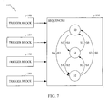
- FIGURE 7 presents sequencer flow diagram 190.
- sequencer process 180 operates in the shown example at three states, S0:S2.
- S0 states
- S1 sequencing advances either ahead to S2 or back to S0.
- S2 sequencing advances to either S1 or S0.
- Sequencer process 180 therefore, includes three states S0:S2, with the transitions between states being programmable and based on matches from trigger blocks circuits 182:188. Sequencer process 180 has use in trace filtering for enabling each trigger blocks circuits 182:188 to be conditioned on state-enables. This allows tracing to be restricted to certain states.
- the counter in each trigger blocks circuits 182:188 may be reloaded to an initial value.
- an ISDB breakpoint can be asserted.
- a trigger marker can be inserted into the trace stream.
- an external trigger control may also be asserted.
- the external trigger may remain asserted anytime that the sequencer is in the given state.
- an interrupt to DSP 40 may be asserted.
- the counter is initialized to S0. If multiple transitions fire at the same time, the sequencer remains in the current state.
- ETM 162 contains six counters that can record various events related to DSP 40 performance.
- the basic operation makes use of each counter as a programmable source.
- a user-programmable region counter divides execution into windows of a fixed number of cycles. During the window, the events are accumulated into counters. At the end of the window, the counter values are formed into packets and sent out through the trace port. The counters are then reset and the process begins again.
- the profiling unit is operated in at the same time as the program flow tracing, this results in the program flow trace being overlaid with detailed information about performance events.
- the profiling unit contains a state-enable mask to limit when the unit is active.
- a region counter is used to divide up the execution into windows of a fixed number of cycles. The size of the region is determined by a user-programmable register. The region counter is initialized to the user-specified value, and all of the profiling-event counters are reset. The region counter then begins counting down. When the region counter reaches zero, the value for each of the profiling-event counts is emitted in the trace stream. The process then begins again. The region-counter only counts when the state-enable matches. When the profiling is inactive, the region counter maintains its value and resumes when an enabled state is re-entered.
- each profiling counter contains a six-thread mask to restrict the counter to events that occur in certain hardware threads.
- the profiling counters are only active when the state-enable mask matches the current state. During all other times the counts maintain their values and counting resumes when an enabled state is re-entered.
- the present disclosure provides a novel packet protocol set of functions to support inter-thread trace alignment. That is, for any thread that is being traced using ETM 162, at any arbitrary point in time, the present disclosure allows identifying for all other threads being traced the program counter value and instruction state (e.g., stalled, executed, etc.) of those threads at that point.
- trace-alignment makes use of a trace-port protocol supporting inter-thread trace alignment.
- the present disclosure therefore, make cycle-count fields for isync-restart packets thread-relative, as well as the cycle-count field fully precise for inter-thread alignment.
- the disclosure arrangement generates an isync-periodic packet on the same thread cycle for all threads. This further allows for re-alignment, in the event that thread alignment is lost for any reason.
- DSP 40 may be viewed as several single-threaded processors operating independently.
- ETM 162 program flow is broken down into a sequence of packets and that include thread number (tnum) fields to certain packets to identify which packet belongs to which thread.
- tnum thread number
- the present disclosure establishes and maintains timing relationships between different threads. Because each thread may enable and disable instruction tracing independently, when a thread turns on instruction tracing, other threads may already have had their tracing enabled for some time.
- the presently disclosed method and system establish the relative timing of the threads execution sequences by marking the offset between when a thread turns on tracing and when other threads have turned on and do subsequently turn on tracing.
- the present disclosure therefore, includes a thread cycle-offset field for indicating the number of cycles since the last thread turned on tracing. Also, if no other threads are active, the cycle-offset field contains the number of cycles since the most recent trace turn-off among all threads. After a trace session, the packets allow for reconstructing the thread execution. Then, using the offset-fields, the execution sequences may be properly aligned among the threads. In addition, an instruction-alignment mechanism allows re-establishing execution tracing in case of a data loss.
- the disclosed subject matter furthermore allows re-establishing the inter-thread timing relationships.
- a packet may be generated for each thread.
- Such a packet contains the current program counter value for that thread.
- the present disclosure includes a cycle-offset field to a synchronization packet.
- the cycle-offset field indicates the number of cycles since the last thread (among the other threads) generated a synchronization packet.
- the cycle-offset field is of limited size and if the count saturates, synchronization will not be able to be achieved and may wait for the counter.
- the present disclosure allows maintaining inter-thread execution timing relationships at any given point for one thread. The result is the ability to observe operations and states of all threads for debugging and other important purposes.
- FIGURE 8 illustrates important concepts of the presently disclosed inter-thread trace alignment process.
- thread initiation may occur at different points in time.
- thread 204 may initiate operations.
- duration 214 represents the number of cycles until tracing becomes active for thread 212.
- Duration 214 represents the number of cycles for the trace-start program counter (PC) from the isync-restart packet.
- PC trace-start program counter
- duration 220 addresses the situation of a long stall occurring, for example, in thread 212.
- FIGURE 9 shows a functional overview of one embodiment of a packet generation unit 230.
- Packet generation unit 230 includes packet generation control circuitry 232, which received inputs of atomW, atomN, and atomE for generating outputs of genIsyncP, genAsync, genBranch, genPheader, genIsyncR, genProf, and genCCount to FIFO input mux 234 .
- Pheader generation circuit 236 receives w-count, e-count, and n-count inputs from packet generation control circuit 232 and atomE input, all for generating pheaderPK output to FIFO input mux 234.
- PC/tld/asid/tnum input flows to isync-restart/cycle-count generation functions 238, isync-periodic generation functions 240, and branch-address generation functions 242.
- Isync-restart/cycle count generation functions 238 provide isyncRPK, isyncRLen, CCPK, and CCLen outputs to FIFO input mux 234.
- Isync-periodic generation functions 240 provide isyncPPK and isyncPLen inputs into FIFO input mux 234.
- Branch-address generation functions 242, which also receives branch-type inputs, provides branchPK and branchLen outputs to FIFO input mux 234.
- profile generations functions 244 receives profile identifier inputs for generating profPK and profLen outputs to FIFO input mux 234.
- FIFO input mux 234 takes all of the packets that need to be generated on a given cycle and forms them into a contiguous chunk. FIFO input mux 234 must account for packets being variable sized when doing its concatenation. The output of FIFO input mux 234 is registered before being sent to the FIFO.
- packet generation and FIFO input mux 234 operations occur across three stages.
- packet generation control functions 232 and individual packet generation engines 236 through 244 operates, as well as atom counters w-count, e-count, and n-count increment.
- FIFO input mux 234 operations include merging all packets generated in the cycle into a contiguous block in this first stage.
- FIFO write occurs to include rotating data to align to FIFO write pointer, computing and rotating write-enables, and writing data into FIFO mux 234 registers.
- FIFO read stage data may be read from FIFO registers.
- the special case of inserting the trigger packet and sending data to ETB occurs.
- each of the individual packet generation units packetizes its respective data and then sends the resulting packet and length to FIFO input mux 234 for concatenation.
- packet generation control circuit 232 maintains the atom counters and decides which packets to generate on a particular cycle.
- Packet generation unit 230 maintains three counters to record the number of pending atoms that may be sent out in future pheader or cycle-count packet.
- the E-atom counter increments whenever an E-atom is encountered.
- the N-atom counter increments whenever an N-atom is encountered and the count includes the current atom. That is, if the current atom is an N, it will be included in the N-atom count.
- the W-atom counter increments whenever a W-atom is encountered. These counters are per-thread counters and, as such, there are six copies of each in the present embodiment. The counters are reset whenever the counts are sent out through a pheader or cycle-count packet.
- a branch address packet may be generated for a target of an indirect branch loopback, if the target is different from previous loopback. If all-loopbacks mode is set, the packet is sent out for every loopback. Also a new loopback packet is forced out after an isync-restart and isync-periodic packet is generated. The target of a PC-relative branch IF direct-branches mode is then set. The target of an event (interrupt, exception, SWI, TRAP, etc.) returns the RTE instruction.
- the branch-address packet may be generated when trace-enable is asserted and it is not the first cycle of tracing (an isync-restart packet may be generated instead).
- the packet generation control unit maintains a previous-loopback target register for each thread to determine if a loopback branch-address packet is needed.
- FIGURE 10 shows table 250 of definitions for the various atoms applicable to the instructions of the presently disclosed subject matter.
- a major goal of the packet protocol is to support inter-thread trace alignment. That is, for any thread that is being traced, at any arbitrary point in time, the user should be able to identify for all other threads being traced the program counter value and instruction state (stalled, executed) of those threads at that point. Trace-alignment works when ETM 162 operates in cycle-accurate mode.
- the trace-port protocol has been extended to support inter-thread trace alignment.
- An 'S' type instruction atom provides a branch mechanism known as a dual jump.
- ETM 162 includes an S-type, which is defined using a pheader-format4 packet type to hold the atom.
- FIGURE 11 provides a branch-address packet 280 for the present disclosure that supports a 32-bit TID field.
- the presently disclosed branch-address packet supports a 32-bit TID field, the contents of appear in FIGURE 11 .
- the branch-address packet is variable length, including between 1 and 11 bytes. Continuation bits in the MSBs of bytes 0 through 4 indicate if packet continues beyond that point. Separately, the T-bit indicates whether a type-field will be appended to the end of the packet. A1 in the MSB of byte-4 indicates that 5 bytes will follow (4 bytes of the TID and 1 byte of ASID).
- the branch-address packet is variable with PC, TID/ASID, and type compression.
- the TID/ASID may be sent out if either one has changed since the last branch-address packet or isync (restart or periodic) for the tnum.
- the type may be sent out if it has changed since the last type was sent out. It may be generated on the first branch-address packet after a isync-restart or isync-periodic.
- the PC is compressed relative to the previous PC sent by a branch-address, isync-restart, or isync-periodic. The lower portion of the PC that has changed may be sent out. For each thread, previous PC, previous TID/ASID, and previous type registers are used to determine the proper compression.
- FIGURE 12 present exemplary contents of an isync-restart packet 260 for use in the presently disclosed process.
- the isync-restart packet may be generated when tracing is initiated (trace-enable was previously low).
- an isync-restart packet is generated with the reason field indicating that there was an overflow.
- the present disclosure provides alignment using isync-restart packets. Instruction alignment can be viewed as assigning a global thread-cycle to every cycle of every thread being traced. A decompressor procedure accomplishes this for the case when isync-restart packets are available in the trace stream. The decompressor will maintain a counter value of the last isync-restart-count.
- the present disclosure may inspect the cycle-count field and cycle-count type field. If the type-field is 'global', the process assigns a last-isync-restart-count to the cycle-count field value and annotates that packet with last-isync-restart-count. If the type-field is 'offset', the process may increment the last-isync-restart-count by the value in the cycle-count field and further annotate the packet with last-isync-restart-count. At which point, each isync-restart packet will be annotated with a global thread-cycle value.
- the next step is to annotate the atoms.
- the process splits the trace-stream into the individual thread-local packet-streams based on the tnum values in the packet-stream. For each thread-local packet-stream, the process maintains a variable global-thread-cycle. This value is maintained such that anytime an isync-restart packet is encountered, global-thread-cycle is assigned to the value that was annotated. Each time an instruction atom is encountered (E, N, S, or W) the process may annotate that atom with global-thread-cycle and increment global-thread-cycle by 1. Using the normal decompression procedure, the process determines the program counter values for each atom.
- every cycle of every thread being traced may be annotated with a global thread-cycle count value.
- the current program counter value for all six threads may be determined, as well as the state of the pipeline for those threads (stalled, executed, etc.)
- the TID field is expanded to 32-bits.
- the TID is expanded to 32-bits and the new cycle-count field is defined to support trace-alignment.
- a global cycle-count indicates the number of thread-cycles since the last hardware reset.
- An offset cycle-count indicates the number of cycles since the last isync-restart packet was generated.
- FIGURE 13 depicts an embodiment of an isync-periodic packet 290 for supporting the presently disclosed subject matter.
- Isync-periodic packets include an 'offset' field that indicates the number of thread-cycles since the last isync-periodic packet has been generated (from among all threads).
- the disclosed process also supports alignment using isync-periodic packets. In some cases only a limited window of trace data is available. Therefore an isync-restart packet may not be available. In these cases the isync-periodic packet may be used to determine inter-thread alignment. If packet boundaries are unknown, the process may search for an async-packet to recover packet alignment.
- the decompressor may maintain a counter last-isync-periodic-count. Going through the multi-thread packet stream, the process may include searching for the oldest isync-periodic packet that does not have an offset field. Then, the process may assign the last-isync-periodic-count to 0 and annotates that packet with the value. For each of the following isync-periodic packets from the other tnums, the process may increment the isync-periodic-count by the offset-field value and each of the isync-periodic packets with isync-periodic-count. Then, the process may split the threads into individual packet-streams and decompresses them separately.
- the ETM isync-periodic counters may be decremented whenever packet bytes are sent to the FIFO. When the counter reaches zero for a thread, an isync-periodic packet may be marked as pending. At the next opportunity, the isync-periodic packet is generated. An isync-periodic may be held back if any of the following packets are being generated (isync-restart, trigger, branch-address, async, profile). Each thread may maintain its own isync-periodic counter. The isync counters may be reset whenever any isync-restart packet is generated for that thread.
- FIGURE 14 presents a set of cycle count packets for use in the presently disclosed process.
- a cycle-count packet may be used to accumulate W-atoms. Also the cycle-count packet may only generated in cycle-accurate mode.
- the cycle-count packet may be generated in the following cases: switch from W to E or W to N and W-atom count does not fit into format-3 pheader capacity, atom-break with W atoms pending and too many W atoms to fit into a format-3 pheader.
- the W-atoms may be placed into the cycle-count packet and the E or N atom may come out in a format-1 pheader, and cycle-count packet may reach its fully-accurate maximum.
- the ETM sends out multiple smaller cycle-count values at the limit between full accuracy and limited accuracy.
- the current atom may be a W-atom. Because this atom is not included in the packet, the count is reset to 1 instead of 0.
- the cycle-count in the isync-restart packet has been redefined as two possible types: a 64-bit 'global' count that is referenced from the last hardware reset, and a 16-bit offset count that indicates the number of thread cycles since the last isync-restart packet (from among all threads).
- the present disclosure provides a three-byte packet 320 to fit a 32-bit value into the 16-bit payload.
- a five-byte packet which includes a one-byte header and four-byte payload is defined as shown in FIGURE 14 .
- the disclosed process maintains a count global-thread-cycle. For the first isync-periodic packet that is encountered, the process sets a global-thread-cycle to that packet's annotated value and annotates the previous atom with that value. The global-thread-cycle is then incremented by 1.
- FIGURE 15 shows one embodiment of a pheader format4 packet 330 as relevant to the present disclosure.
- the pheader packets may be generated in different cases. For example, when no more atoms can be held in the packet, and when a branch-address, profile, or isync-periodic packet is generated, a pheader is generated to mark the location of the respective packet within the atom stream.
- the format-1 pheader packet may have three atom payload fields: from 0 to 31 E atoms (field-0), followed by 0 to 3 N atoms (field-1), followed by 0 or 1 E atom (field-2).
- the rules for generating format-1 pheader packets may be: atom-E count at maximum, and current atom is an E.
- the counted E's will go into field-0, and the current E atom may be placed into field-2.
- Counted E's may be placed into field-0 and N atom count may be placed into field-1.
- the current atom is E and the N atom count is non zero.
- the counted E and N atom counts may be placed in field-0 and field-1 and the current E atoms may be placed in field-2.
- the current E and N counts may be sent out in payload field-0 and field-1.
- current E and N counts may be placed in field-0 and field-1, and if the current atom is E, it may be placed in field-2.
- FIGURE 16 depicts an async packet 340 for use with an embodiment of the disclosed subject matter.
- the async packet length accommodates a longer cycle-count fields and may, for example, include ten bytes.
- the async-periodic counter may also be used to define when async packets are generated. An async packet is marked as pending whenever the ETM periodic counter reaches. The async packet must come out by itself, and will remain pending whenever other packets are generated.
- the async counter is global and may be decremented whenever packet bytes are sent to the FIFO.
- the disclosed subject matter provides a method and system for inter-thread trace alignment with a multi-threaded processor for use with execution trace processing.
- the disclosed subject matter therefore, includes recording timing data relating to a common predetermined event.
- Such an event may be the number of cycles since a last thread initiated execution tracing or the number of cycles since all threads terminated execution tracing.
- the number of cycles at which a thread initiates execution tracing is referenced to the common predetermined event for maintaining the timing of execution tracing.
- the data relating to the common predetermined event may then updated to associate with the time at which the thread initiated execution tracing.
- the result is to permit aligning the timing data associated with all threads.
- Interrelated records permit reconstructing interdependent execution tracing information for threads operating in the multi-threaded processor, as well as synchronizing timing data for all operating threads.
- the processing features and functions described herein for inter-thread trace alignment with a multi-threaded processor in a multi-threaded digital signal processor may be implemented in various manners.
- DSP 40 perform the above-described operations
- present embodiments may be implemented in an application specific integrated circuit (ASIC), a microcontroller, a digital signal processor, or other electronic circuits designed to perform the functions described herein.
- ASIC application specific integrated circuit
- the process and features here described may be stored in magnetic, optical, or other recording media for reading and execution by such various signal and instruction processing systems.
Landscapes
- Engineering & Computer Science (AREA)
- Theoretical Computer Science (AREA)
- Physics & Mathematics (AREA)
- General Engineering & Computer Science (AREA)
- General Physics & Mathematics (AREA)
- Quality & Reliability (AREA)
- Computer Hardware Design (AREA)
- Software Systems (AREA)
- Debugging And Monitoring (AREA)
- Executing Machine-Instructions (AREA)
Applications Claiming Priority (1)
| Application Number | Priority Date | Filing Date | Title |
|---|---|---|---|
| US11/734,199 US8484516B2 (en) | 2007-04-11 | 2007-04-11 | Inter-thread trace alignment method and system for a multi-threaded processor |
Publications (3)
| Publication Number | Publication Date |
|---|---|
| EP2037367A2 true EP2037367A2 (de) | 2009-03-18 |
| EP2037367A3 EP2037367A3 (de) | 2010-03-17 |
| EP2037367B1 EP2037367B1 (de) | 2018-04-18 |
Family
ID=39854865
Family Applications (1)
| Application Number | Title | Priority Date | Filing Date |
|---|---|---|---|
| EP08005116.2A Not-in-force EP2037367B1 (de) | 2007-04-11 | 2008-03-19 | Verfahren und System zur Ausrichtung von Zwischen-Thread-Spuren für einen Multi-Thread-Prozessor |
Country Status (8)
| Country | Link |
|---|---|
| US (1) | US8484516B2 (de) |
| EP (1) | EP2037367B1 (de) |
| JP (3) | JP2010524140A (de) |
| KR (1) | KR101072687B1 (de) |
| CN (1) | CN101874238B (de) |
| ES (1) | ES2678413T3 (de) |
| HU (1) | HUE038872T2 (de) |
| WO (1) | WO2008128107A2 (de) |
Families Citing this family (42)
| Publication number | Priority date | Publication date | Assignee | Title |
|---|---|---|---|---|
| US8380966B2 (en) | 2006-11-15 | 2013-02-19 | Qualcomm Incorporated | Method and system for instruction stuffing operations during non-intrusive digital signal processor debugging |
| US8533530B2 (en) | 2006-11-15 | 2013-09-10 | Qualcomm Incorporated | Method and system for trusted/untrusted digital signal processor debugging operations |
| US8341604B2 (en) | 2006-11-15 | 2012-12-25 | Qualcomm Incorporated | Embedded trace macrocell for enhanced digital signal processor debugging operations |
| US8370806B2 (en) | 2006-11-15 | 2013-02-05 | Qualcomm Incorporated | Non-intrusive, thread-selective, debugging method and system for a multi-thread digital signal processor |
| GB2453174B (en) * | 2007-09-28 | 2011-12-07 | Advanced Risc Mach Ltd | Techniques for generating a trace stream for a data processing apparatus |
| US8001428B2 (en) * | 2007-10-29 | 2011-08-16 | Arm Limited | Packing trace protocols within trace streams |
| US9098625B2 (en) * | 2008-02-29 | 2015-08-04 | International Business Machines Corporation | Viral trace |
| US8140903B2 (en) * | 2009-04-16 | 2012-03-20 | International Business Machines Corporation | Hardware process trace facility |
| JP2011100388A (ja) * | 2009-11-09 | 2011-05-19 | Fujitsu Ltd | トレース情報収集装置,トレース情報処理装置,およびトレース情報収集方法 |
| US8484517B2 (en) * | 2009-12-03 | 2013-07-09 | Infineon Technologies Ag | High compression program flow trace |
| US8893092B1 (en) * | 2010-03-12 | 2014-11-18 | F5 Networks, Inc. | Using hints to direct the exploration of interleavings in a multithreaded program |
| US8972995B2 (en) * | 2010-08-06 | 2015-03-03 | Sonics, Inc. | Apparatus and methods to concurrently perform per-thread as well as per-tag memory access scheduling within a thread and across two or more threads |
| US20120042212A1 (en) * | 2010-08-10 | 2012-02-16 | Gilbert Laurenti | Mixed Mode Processor Tracing |
| US8880958B2 (en) * | 2011-09-20 | 2014-11-04 | Qualcomm Incorporated | Interleaved architecture tracing and microarchitecture tracing |
| US10275242B2 (en) * | 2012-03-30 | 2019-04-30 | Intel Corporation | System and method for real time instruction tracing |
| US8910125B2 (en) * | 2012-09-27 | 2014-12-09 | International Business Machines Corporation | Monitoring software performance |
| US8954546B2 (en) * | 2013-01-25 | 2015-02-10 | Concurix Corporation | Tracing with a workload distributor |
| US9928159B2 (en) | 2013-02-26 | 2018-03-27 | Qualcomm Incorporated | System and method to select a packet format based on a number of executed threads |
| CN103226328B (zh) * | 2013-04-21 | 2015-06-24 | 中国矿业大学(北京) | 采集次数控制模式下的多线程数据采集系统同步控制方法 |
| US9218223B2 (en) * | 2013-08-13 | 2015-12-22 | Qualcomm Incorporated | Barrier synchronization with dynamic width calculation |
| US9996354B2 (en) * | 2015-01-09 | 2018-06-12 | International Business Machines Corporation | Instruction stream tracing of multi-threaded processors |
| US10719420B2 (en) * | 2015-02-10 | 2020-07-21 | International Business Machines Corporation | System level testing of multi-threading functionality including building independent instruction streams while honoring architecturally imposed common fields and constraints |
| EP3338192A1 (de) | 2015-08-18 | 2018-06-27 | Telefonaktiebolaget LM Ericsson (PUBL) | Verfahren zur beobachtung von softwareausführung, debug-host und debug-ziel |
| US10013240B2 (en) * | 2016-06-21 | 2018-07-03 | Advanced Micro Devices, Inc. | Fingerprinting of redundant threads using compiler-inserted transformation code |
| US20180054374A1 (en) * | 2016-08-19 | 2018-02-22 | Andes Technology Corporation | Trace information encoding apparatus, encoding method thereof, and readable computer medium |
| US10042737B2 (en) | 2016-08-31 | 2018-08-07 | Microsoft Technology Licensing, Llc | Program tracing for time travel debugging and analysis |
| US10031833B2 (en) * | 2016-08-31 | 2018-07-24 | Microsoft Technology Licensing, Llc | Cache-based tracing for time travel debugging and analysis |
| US10031834B2 (en) | 2016-08-31 | 2018-07-24 | Microsoft Technology Licensing, Llc | Cache-based tracing for time travel debugging and analysis |
| US10310963B2 (en) | 2016-10-20 | 2019-06-04 | Microsoft Technology Licensing, Llc | Facilitating recording a trace file of code execution using index bits in a processor cache |
| US10324851B2 (en) | 2016-10-20 | 2019-06-18 | Microsoft Technology Licensing, Llc | Facilitating recording a trace file of code execution using way-locking in a set-associative processor cache |
| US10489273B2 (en) | 2016-10-20 | 2019-11-26 | Microsoft Technology Licensing, Llc | Reuse of a related thread's cache while recording a trace file of code execution |
| US10310977B2 (en) | 2016-10-20 | 2019-06-04 | Microsoft Technology Licensing, Llc | Facilitating recording a trace file of code execution using a processor cache |
| US10540250B2 (en) | 2016-11-11 | 2020-01-21 | Microsoft Technology Licensing, Llc | Reducing storage requirements for storing memory addresses and values |
| EP4036737A1 (de) * | 2016-11-11 | 2022-08-03 | Microsoft Technology Licensing, LLC | Cache-basierte verfolgung für zeit-weg-debugging und analyse |
| US10169194B2 (en) * | 2017-03-22 | 2019-01-01 | International Business Machines Corporation | Multi-thread sequencing |
| US10318332B2 (en) | 2017-04-01 | 2019-06-11 | Microsoft Technology Licensing, Llc | Virtual machine execution tracing |
| US10296442B2 (en) | 2017-06-29 | 2019-05-21 | Microsoft Technology Licensing, Llc | Distributed time-travel trace recording and replay |
| US10459824B2 (en) | 2017-09-18 | 2019-10-29 | Microsoft Technology Licensing, Llc | Cache-based trace recording using cache coherence protocol data |
| US10558572B2 (en) | 2018-01-16 | 2020-02-11 | Microsoft Technology Licensing, Llc | Decoupling trace data streams using cache coherence protocol data |
| US11907091B2 (en) | 2018-02-16 | 2024-02-20 | Microsoft Technology Licensing, Llc | Trace recording by logging influxes to an upper-layer shared cache, plus cache coherence protocol transitions among lower-layer caches |
| US10642737B2 (en) | 2018-02-23 | 2020-05-05 | Microsoft Technology Licensing, Llc | Logging cache influxes by request to a higher-level cache |
| US10496537B2 (en) | 2018-02-23 | 2019-12-03 | Microsoft Technology Licensing, Llc | Trace recording by logging influxes to a lower-layer cache based on entries in an upper-layer cache |
Citations (1)
| Publication number | Priority date | Publication date | Assignee | Title |
|---|---|---|---|---|
| WO2006030195A2 (en) | 2004-09-14 | 2006-03-23 | Coware, Inc. | Mehtod and system for debugging a multi- threaded program executing in a multicore architecture |
Family Cites Families (161)
| Publication number | Priority date | Publication date | Assignee | Title |
|---|---|---|---|---|
| US4080650A (en) * | 1976-07-28 | 1978-03-21 | Bell Telephone Laboratories, Incorporated | Facilitating return from an on-line debugging program to a target program breakpoint |
| US4669059A (en) * | 1983-11-07 | 1987-05-26 | Motorola, Inc. | Method and apparatus in a data processor for selectively disabling a power-down instruction |
| US4901307A (en) * | 1986-10-17 | 1990-02-13 | Qualcomm, Inc. | Spread spectrum multiple access communication system using satellite or terrestrial repeaters |
| US5136717A (en) * | 1988-11-23 | 1992-08-04 | Flavors Technology Inc. | Realtime systolic, multiple-instruction, single-data parallel computer system |
| US5093914A (en) * | 1989-12-15 | 1992-03-03 | At&T Bell Laboratories | Method of controlling the execution of object-oriented programs |
| US5103459B1 (en) * | 1990-06-25 | 1999-07-06 | Qualcomm Inc | System and method for generating signal waveforms in a cdma cellular telephone system |
| US5551043A (en) * | 1994-09-07 | 1996-08-27 | International Business Machines Corporation | Standby checkpoint to prevent data loss |
| US6467054B1 (en) | 1995-03-13 | 2002-10-15 | Compaq Computer Corporation | Self test for storage device |
| CA2228014C (en) * | 1995-07-31 | 2008-07-22 | Verifone, Inc. | Method and apparatus for operating resources under control of a security module or other secure processor |
| US5544311A (en) * | 1995-09-11 | 1996-08-06 | Rockwell International Corporation | On-chip debug port |
| US5951696A (en) | 1996-11-14 | 1999-09-14 | Hewlett-Packard Company | Debug system with hardware breakpoint trap |
| JPH10207790A (ja) * | 1997-01-20 | 1998-08-07 | Fuji Xerox Co Ltd | 入出力制御装置 |
| US5915083A (en) * | 1997-02-28 | 1999-06-22 | Vlsi Technology, Inc. | Smart debug interface circuit for efficiently for debugging a software application for a programmable digital processor device |
| US5835705A (en) * | 1997-03-11 | 1998-11-10 | International Business Machines Corporation | Method and system for performance per-thread monitoring in a multithreaded processor |
| US6275868B1 (en) * | 1997-03-12 | 2001-08-14 | Microsoft Corporation | Script Engine interface for multiple languages |
| US6094729A (en) | 1997-04-08 | 2000-07-25 | Advanced Micro Devices, Inc. | Debug interface including a compact trace record storage |
| US6314530B1 (en) | 1997-04-08 | 2001-11-06 | Advanced Micro Devices, Inc. | Processor having a trace access instruction to access on-chip trace memory |
| US5944841A (en) * | 1997-04-15 | 1999-08-31 | Advanced Micro Devices, Inc. | Microprocessor with built-in instruction tracing capability |
| US6199181B1 (en) * | 1997-09-09 | 2001-03-06 | Perfecto Technologies Ltd. | Method and system for maintaining restricted operating environments for application programs or operating systems |
| US6697935B1 (en) | 1997-10-23 | 2004-02-24 | International Business Machines Corporation | Method and apparatus for selecting thread switch events in a multithreaded processor |
| US6567839B1 (en) * | 1997-10-23 | 2003-05-20 | International Business Machines Corporation | Thread switch control in a multithreaded processor system |
| US6212544B1 (en) * | 1997-10-23 | 2001-04-03 | International Business Machines Corporation | Altering thread priorities in a multithreaded processor |
| US6029248A (en) * | 1997-12-15 | 2000-02-22 | Lucent Technologies Inc. Corporation | Locking system to protect a powered component interface from erroneous access by an attached, powered-off component |
| US6018759A (en) * | 1997-12-22 | 2000-01-25 | International Business Machines Corporation | Thread switch tuning tool for optimal performance in a computer processor |
| US6106571A (en) * | 1998-01-29 | 2000-08-22 | Applied Microsystems Corporation | Relocatable instrumentation tags for testing and debugging a computer program |
| US6249907B1 (en) * | 1998-03-24 | 2001-06-19 | International Business Machines Corporation | Method system and article of manufacture for debugging a computer program by encoding user specified breakpoint types at multiple locations in the computer program |
| US6757829B1 (en) * | 1998-05-29 | 2004-06-29 | Texas Instruments Incorporated | Program debugging system for secure computing device having secure and non-secure modes |
| DE19835610A1 (de) * | 1998-08-06 | 2000-02-10 | Siemens Ag | Programmgesteuerte Einheit und Verfahren zum Debuggen derselben |
| US6480818B1 (en) * | 1998-11-13 | 2002-11-12 | Cray Inc. | Debugging techniques in a multithreaded environment |
| US6532553B1 (en) * | 1998-12-08 | 2003-03-11 | Arm Limited | Debugging data processing systems |
| US6343371B1 (en) * | 1999-01-14 | 2002-01-29 | Compaq Computer Corporation | System and method for statically detecting potential race conditions in multi-threaded computer programs |
| US6535905B1 (en) | 1999-04-29 | 2003-03-18 | Intel Corporation | Method and apparatus for thread switching within a multithreaded processor |
| US6341347B1 (en) * | 1999-05-11 | 2002-01-22 | Sun Microsystems, Inc. | Thread switch logic in a multiple-thread processor |
| US6714958B1 (en) * | 1999-07-28 | 2004-03-30 | International Business Machines Corporation | Detecting and causing latent deadlocks in multi-threaded programs |
| WO2001018651A1 (en) | 1999-09-07 | 2001-03-15 | Koninklijke Philips Electronics N.V. | Thread-oriented debugging |
| US6684348B1 (en) * | 1999-10-01 | 2004-01-27 | Hitachi, Ltd. | Circuit for processing trace information |
| WO2001033351A1 (fr) * | 1999-10-29 | 2001-05-10 | Fujitsu Limited | Architecture de processeur |
| GB2362730B (en) | 1999-12-23 | 2004-02-11 | St Microelectronics Sa | Computer register watch |
| US6665802B1 (en) | 2000-02-29 | 2003-12-16 | Infineon Technologies North America Corp. | Power management and control for a microcontroller |
| US6725391B2 (en) * | 2000-03-02 | 2004-04-20 | Texas Instruments Incorporated | Clock modes for a debug port with on the fly clock switching |
| US6785850B2 (en) * | 2000-03-02 | 2004-08-31 | Texas Instruments Incorporated | System and method for automatically configuring a debug system |
| US6928403B2 (en) * | 2000-03-02 | 2005-08-09 | Texas Instruments Incorporated | Automatic detection of connectivity between an emulator and a target device |
| US6934937B1 (en) | 2000-03-30 | 2005-08-23 | Broadcom Corporation | Multi-channel, multi-service debug on a pipelined CPU architecture |
| JP2001331340A (ja) | 2000-05-19 | 2001-11-30 | Nec Corp | コードチェックによるモード切替方式および方法 |
| US20020065646A1 (en) * | 2000-09-11 | 2002-05-30 | Waldie Arthur H. | Embedded debug system using an auxiliary instruction queue |
| US6691251B2 (en) * | 2000-11-30 | 2004-02-10 | Palmsource, Inc. | On-chip debugging system emulator |
| US7020871B2 (en) * | 2000-12-21 | 2006-03-28 | Intel Corporation | Breakpoint method for parallel hardware threads in multithreaded processor |
| US6915416B2 (en) * | 2000-12-28 | 2005-07-05 | Texas Instruments Incorporated | Apparatus and method for microcontroller debugging |
| US7093236B2 (en) * | 2001-02-01 | 2006-08-15 | Arm Limited | Tracing out-of-order data |
| US7069544B1 (en) | 2001-04-30 | 2006-06-27 | Mips Technologies, Inc. | Dynamic selection of a compression algorithm for trace data |
| US7134116B1 (en) * | 2001-04-30 | 2006-11-07 | Mips Technologies, Inc. | External trace synchronization via periodic sampling |
| US7076804B2 (en) | 2001-05-11 | 2006-07-11 | International Business Machines Corporation | Automated program resource identification and association |
| US7073059B2 (en) * | 2001-06-08 | 2006-07-04 | Hewlett-Packard Development Company, L.P. | Secure machine platform that interfaces to operating systems and customized control programs |
| US7752423B2 (en) * | 2001-06-28 | 2010-07-06 | Intel Corporation | Avoiding execution of instructions in a second processor by committing results obtained from speculative execution of the instructions in a first processor |
| US7823131B2 (en) | 2001-06-29 | 2010-10-26 | Mentor Graphics Corporation | Debugger for a hardware-implemented operating system |
| JP2003177938A (ja) * | 2001-12-07 | 2003-06-27 | Fujitsu Ltd | 電子装置及びそのデバッグ認証方法 |
| US7131114B2 (en) | 2001-07-16 | 2006-10-31 | Texas Instruments Incorporated | Debugger breakpoint management in a multicore DSP device having shared program memory |
| US7134002B2 (en) | 2001-08-29 | 2006-11-07 | Intel Corporation | Apparatus and method for switching threads in multi-threading processors |
| US7017084B2 (en) * | 2001-09-07 | 2006-03-21 | Network Appliance Inc. | Tracing method and apparatus for distributed environments |
| US6901527B2 (en) * | 2001-09-21 | 2005-05-31 | International Business Machines Corporation | Synchronizing multiple time stamps distributed within a computer system with main time of day register |
| DE10148109B4 (de) * | 2001-09-28 | 2006-10-12 | Infineon Technologies Ag | Verfahren zum Speichern oder Weiterleiten von Daten |
| US7080289B2 (en) * | 2001-10-10 | 2006-07-18 | Arm Limited | Tracing multiple data access instructions |
| US20030074650A1 (en) * | 2001-10-17 | 2003-04-17 | Tankut Akgul | Debugger operating system for embedded systems |
| US6834360B2 (en) * | 2001-11-16 | 2004-12-21 | International Business Machines Corporation | On-chip logic analyzer |
| US20030135720A1 (en) * | 2002-01-14 | 2003-07-17 | International Business Machines Corporation | Method and system using hardware assistance for instruction tracing with secondary set of interruption resources |
| US7254716B1 (en) | 2002-02-13 | 2007-08-07 | Lsi Corporation | Security supervisor governing allowed transactions on a system bus |
| US7213134B2 (en) * | 2002-03-06 | 2007-05-01 | Hewlett-Packard Development Company, L.P. | Using thread urgency in determining switch events in a temporal multithreaded processor unit |
| US6615371B2 (en) | 2002-03-11 | 2003-09-02 | American Arium | Trace reporting method and system |
| US7055139B2 (en) * | 2002-03-28 | 2006-05-30 | Hewlett-Packard Development Company, L.P. | Multiprocess debugging using multiple conventional debuggers |
| GB2389432B (en) * | 2002-06-07 | 2005-09-07 | Advanced Risc Mach Ltd | Instruction tracing in data processing systems |
| US7003703B2 (en) | 2002-06-21 | 2006-02-21 | Sandbridge Technologies, Inc. | Method of interleaving/deinterleaving in a communication system |
| US7516446B2 (en) * | 2002-06-25 | 2009-04-07 | International Business Machines Corporation | Method and apparatus for efficient and precise datarace detection for multithreaded object-oriented programs |
| US7185319B2 (en) * | 2002-07-09 | 2007-02-27 | Microsoft Corporation | Debugging distributed applications |
| US7512954B2 (en) * | 2002-07-29 | 2009-03-31 | Oracle International Corporation | Method and mechanism for debugging a series of related events within a computer system |
| US7346895B2 (en) * | 2002-07-31 | 2008-03-18 | International Business Machines Corporation | Method of tracing data collection |
| US7529258B2 (en) * | 2002-08-09 | 2009-05-05 | Lecroy Corporation | Method and system for cascading analyzer trace memories |
| DE10244922B4 (de) * | 2002-09-25 | 2009-08-13 | Infineon Technologies Ag | Programmgesteuerte Einheit und Verfahren zum Debuggen von einer programmgesteuerten Einheit ausgeführten Programmen |
| US7519862B2 (en) | 2002-10-11 | 2009-04-14 | Broadcom Corporation | Software programmable verification tool having a single built-in self-test (BIST) module for testing and debugging multiple memory modules in a device under test (DUT) |
| US7360117B1 (en) | 2002-10-24 | 2008-04-15 | Verisilicon Holdings (Cayman Islands) Co. Ltd. | In-circuit emulation debugger and method of operation thereof |
| GB2396930B (en) | 2002-11-18 | 2005-09-07 | Advanced Risc Mach Ltd | Apparatus and method for managing access to a memory |
| GB2396034B (en) | 2002-11-18 | 2006-03-08 | Advanced Risc Mach Ltd | Technique for accessing memory in a data processing apparatus |
| US7370210B2 (en) * | 2002-11-18 | 2008-05-06 | Arm Limited | Apparatus and method for managing processor configuration data |
| GB2411254B (en) | 2002-11-18 | 2006-06-28 | Advanced Risc Mach Ltd | Monitoring control for multi-domain processors |
| US6948155B2 (en) * | 2002-11-22 | 2005-09-20 | Texas Instruments Incorporated | Little offset in multicycle event maintaining cycle accurate tracing of stop events |
| US7047451B2 (en) * | 2002-11-22 | 2006-05-16 | Texas Instruments Incorporated | Tracing program counter addresses using native program counter format and instruction count format |
| US7219333B2 (en) * | 2002-11-22 | 2007-05-15 | Texas Instruments Incorporated | Maintaining coherent synchronization between data streams on detection of overflow |
| US7131113B2 (en) * | 2002-12-12 | 2006-10-31 | International Business Machines Corporation | System and method on generating multi-dimensional trace files and visualizing them using multiple Gantt charts |
| US7325169B2 (en) * | 2002-12-17 | 2008-01-29 | Texas Instruments Incorporated | Apparatus and method for trace stream identification of multiple target processor events |
| JP4436036B2 (ja) * | 2002-12-18 | 2010-03-24 | インターナショナル・ビジネス・マシーンズ・コーポレーション | 情報処理装置、トレース処理方法、プログラム及び記録媒体 |
| US6798713B1 (en) | 2003-01-31 | 2004-09-28 | Zilog, Inc. | Implementing software breakpoints |
| JP3974063B2 (ja) * | 2003-03-24 | 2007-09-12 | 松下電器産業株式会社 | プロセッサおよびコンパイラ |
| US7142246B2 (en) | 2003-03-31 | 2006-11-28 | Macronix International Co., Ltd. | Apparatus and method for de-interlacing video, including 3:2 pulldown video |
| US7013400B2 (en) * | 2003-04-24 | 2006-03-14 | International Business Machines Corporation | Method for managing power in a simultaneous multithread processor by loading instructions into pipeline circuit during select times based on clock signal frequency and selected power mode |
| US7047337B2 (en) * | 2003-04-24 | 2006-05-16 | International Business Machines Corporation | Concurrent access of shared resources utilizing tracking of request reception and completion order |
| US7159101B1 (en) * | 2003-05-28 | 2007-01-02 | Mips Technologies, Inc. | System and method to trace high performance multi-issue processors |
| US7222262B2 (en) * | 2003-08-05 | 2007-05-22 | Newisys, Inc. | Methods and devices for injecting commands in systems having multiple multi-processor clusters |
| US7069176B2 (en) * | 2003-08-07 | 2006-06-27 | Arm Limited | Trace source correlation in a data processing apparatus |
| US7383537B2 (en) * | 2003-08-20 | 2008-06-03 | Microsoft Corporation | Debugging an application that employs rights-managed content |
| US7600221B1 (en) * | 2003-10-06 | 2009-10-06 | Sun Microsystems, Inc. | Methods and apparatus of an architecture supporting execution of instructions in parallel |
| US7321957B2 (en) * | 2003-10-24 | 2008-01-22 | Intel Corporation | Debugging a trusted component in a system |
| TWI226757B (en) | 2003-11-11 | 2005-01-11 | Benq Corp | Address generator for block interleaving |
| US7328429B2 (en) * | 2003-11-13 | 2008-02-05 | Intel Corporation | Instruction operand tracing for software debug |
| US7383540B2 (en) * | 2003-12-12 | 2008-06-03 | International Business Machines Corporation | Altering execution flow of a computer program |
| US7475303B1 (en) * | 2003-12-29 | 2009-01-06 | Mips Technologies, Inc. | HyperJTAG system including debug probe, on-chip instrumentation, and protocol |
| EP1711897A4 (de) | 2004-02-05 | 2007-03-21 | Research In Motion Ltd | Debuggen einer port-sicherheits-schnittstelle |
| US7360203B2 (en) * | 2004-02-06 | 2008-04-15 | Infineon Technologies North America Corp. | Program tracing in a multithreaded processor |
| US7263599B2 (en) * | 2004-02-06 | 2007-08-28 | Infineon Technologies | Thread ID in a multithreaded processor |
| JP4347082B2 (ja) * | 2004-02-23 | 2009-10-21 | 日本電気株式会社 | イベントトレースデータの時刻補正装置,時刻補正方法及び時刻補正プログラム |
| JP4409349B2 (ja) | 2004-04-27 | 2010-02-03 | Okiセミコンダクタ株式会社 | デバッグ回路およびデバッグ制御方法 |
| US7945900B2 (en) * | 2004-04-29 | 2011-05-17 | Marvell International Ltd. | Debugging tool for debugging multi-threaded programs |
| US20060253894A1 (en) | 2004-04-30 | 2006-11-09 | Peter Bookman | Mobility device platform |
| US7380276B2 (en) | 2004-05-20 | 2008-05-27 | Intel Corporation | Processor extensions and software verification to support type-safe language environments running with untrusted code |
| US7558920B2 (en) | 2004-06-30 | 2009-07-07 | Intel Corporation | Apparatus and method for partitioning a shared cache of a chip multi-processor |
| US7363523B2 (en) | 2004-08-31 | 2008-04-22 | Intel Corporation | Method and apparatus for controlling power management state transitions |
| JP4520788B2 (ja) * | 2004-07-29 | 2010-08-11 | 富士通株式会社 | マルチスレッドプロセッサ |
| US7278058B1 (en) * | 2004-08-25 | 2007-10-02 | Unisys Corporation | Methods and apparatus to diagnose software |
| US7814308B2 (en) | 2004-08-27 | 2010-10-12 | Microsoft Corporation | Debugging applications under different permissions |
| US9038070B2 (en) * | 2004-09-14 | 2015-05-19 | Synopsys, Inc. | Debug in a multicore architecture |
| US20060129999A1 (en) * | 2004-11-16 | 2006-06-15 | Sony Computer Entertainment Inc. | Methods and apparatus for using bookmarks in a trace buffer |
| US7783925B2 (en) | 2004-12-02 | 2010-08-24 | Texas Instruments Incorporated | Receiving control, data, and control segments of communication scan packets |
| US7681014B2 (en) | 2005-02-04 | 2010-03-16 | Mips Technologies, Inc. | Multithreading instruction scheduler employing thread group priorities |
| US7418629B2 (en) * | 2005-02-11 | 2008-08-26 | International Business Machines Corporation | Synchronizing triggering of multiple hardware trace facilities using an existing system bus |
| US7472378B2 (en) | 2005-02-23 | 2008-12-30 | International Business Machines Corporation | Breakpoint management and reconciliation for embedded scripts in a business integration language specified program process |
| US20060206902A1 (en) | 2005-03-14 | 2006-09-14 | Sujat Jamil | Variable interleaved multithreaded processor method and system |
| US7369954B2 (en) * | 2005-03-17 | 2008-05-06 | International Business Machines Corporation | Event tracing with time stamp compression and history buffer based compression |
| US7747985B2 (en) * | 2005-03-18 | 2010-06-29 | Microsoft Corporation | Conformance testing of multi-threaded and distributed software systems |
| US7917907B2 (en) * | 2005-03-23 | 2011-03-29 | Qualcomm Incorporated | Method and system for variable thread allocation and switching in a multithreaded processor |
| JP2006285430A (ja) | 2005-03-31 | 2006-10-19 | Matsushita Electric Ind Co Ltd | Cpuメモリアクセス解析装置 |
| US7657875B2 (en) * | 2005-04-12 | 2010-02-02 | International Business Machines Corporation | System and method for collecting a plurality of metrics in a single profiling run of computer code |
| US7698686B2 (en) * | 2005-04-15 | 2010-04-13 | Microsoft Corporation | Method and apparatus for performance analysis on a software program |
| US7536597B2 (en) | 2005-04-27 | 2009-05-19 | Texas Instruments Incorporated | Apparatus and method for controlling power, clock, and reset during test and debug procedures for a plurality of processor/cores |
| US7558984B2 (en) | 2005-04-27 | 2009-07-07 | Texas Instruments Incorporated | Apparatus and method for test and debug of a processor/core having advanced power management |
| US8881114B2 (en) * | 2005-05-16 | 2014-11-04 | Texas Instruments Incorporated | Stored program writing stall information when a processor stalls waiting for another processor |
| US7730545B2 (en) | 2005-05-23 | 2010-06-01 | Arm Limited | Test access control for secure integrated circuits |
| US7548911B2 (en) * | 2005-05-28 | 2009-06-16 | Microsoft Corporation | Diagnosing problems in distributed systems |
| JP2007026051A (ja) * | 2005-07-15 | 2007-02-01 | Matsushita Electric Ind Co Ltd | 情報処理装置および情報処理システム |
| US8694621B2 (en) * | 2005-08-19 | 2014-04-08 | Riverbed Technology, Inc. | Capture, analysis, and visualization of concurrent system and network behavior of an application |
| US8196109B2 (en) * | 2005-09-09 | 2012-06-05 | International Business Machines Corporation | Common debug adaptor in a multiple computer programming language environment |
| US9146832B2 (en) | 2005-10-14 | 2015-09-29 | Oracle International Corporation | Debugging functionality embedded in an application |
| JP4388518B2 (ja) * | 2005-11-01 | 2009-12-24 | 株式会社ソニー・コンピュータエンタテインメント | スレッドデバッグ装置、スレッドデバッグ方法及びプログラム |
| US7770155B2 (en) * | 2005-11-03 | 2010-08-03 | International Business Machines Corporation | Debugger apparatus and method for indicating time-correlated position of threads in a multi-threaded computer program |
| US7802233B2 (en) * | 2006-01-30 | 2010-09-21 | Microsoft Corporation | Automated display of trace historical data |
| US20070234306A1 (en) * | 2006-03-31 | 2007-10-04 | Klinger Uwe D | Tracing performance of machine-readable instructions |
| US20080034350A1 (en) * | 2006-04-05 | 2008-02-07 | Conti Gregory R | System and Method for Checking the Integrity of Computer Program Code |
| KR20070109432A (ko) | 2006-05-11 | 2007-11-15 | 삼성전자주식회사 | 커널 인지 디버깅 장치 및 방법 |
| US20070288906A1 (en) * | 2006-05-16 | 2007-12-13 | Texas Instruments Incorporated | Efficient transfer of timing information |
| US7849315B2 (en) | 2006-05-22 | 2010-12-07 | General Dynamics C4 Systems, Inc. | Method for managing operability of on-chip debug capability |
| GB0613289D0 (en) * | 2006-07-04 | 2006-08-16 | Imagination Tech Ltd | Synchronisation of execution threads on a multi-threaded processor |
| US8301870B2 (en) * | 2006-07-27 | 2012-10-30 | International Business Machines Corporation | Method and apparatus for fast synchronization and out-of-order execution of instructions in a meta-program based computing system |
| US8051162B2 (en) * | 2006-07-28 | 2011-11-01 | Hewlett-Packard Development Company, L.P. | Data assurance in server consolidation |
| US7702055B2 (en) * | 2006-09-29 | 2010-04-20 | Mips Technologies, Inc. | Apparatus and method for tracing processor state from multiple clock domains |
| GB2443277B (en) * | 2006-10-24 | 2011-05-18 | Advanced Risc Mach Ltd | Performing diagnostics operations upon an asymmetric multiprocessor apparatus |
| US8341604B2 (en) * | 2006-11-15 | 2012-12-25 | Qualcomm Incorporated | Embedded trace macrocell for enhanced digital signal processor debugging operations |
| US8370806B2 (en) * | 2006-11-15 | 2013-02-05 | Qualcomm Incorporated | Non-intrusive, thread-selective, debugging method and system for a multi-thread digital signal processor |
| US8533530B2 (en) * | 2006-11-15 | 2013-09-10 | Qualcomm Incorporated | Method and system for trusted/untrusted digital signal processor debugging operations |
| US7657791B2 (en) * | 2006-11-15 | 2010-02-02 | Qualcomm Incorporated | Method and system for a digital signal processor debugging during power transitions |
| US8380966B2 (en) * | 2006-11-15 | 2013-02-19 | Qualcomm Incorporated | Method and system for instruction stuffing operations during non-intrusive digital signal processor debugging |
| DE102007009909B4 (de) * | 2007-02-28 | 2016-09-08 | Globalfoundries Inc. | Verfahren zum Validieren einer atomaren Transaktion in einer Multikernmikroprozessorumgebung |
| US9195462B2 (en) * | 2007-04-11 | 2015-11-24 | Freescale Semiconductor, Inc. | Techniques for tracing processes in a multi-threaded processor |
| US7681078B2 (en) | 2007-05-18 | 2010-03-16 | Freescale Semiconductor, Inc. | Debugging a processor through a reset event |
| US8001428B2 (en) * | 2007-10-29 | 2011-08-16 | Arm Limited | Packing trace protocols within trace streams |
-
2007
- 2007-04-11 US US11/734,199 patent/US8484516B2/en active Active
-
2008
- 2008-03-19 EP EP08005116.2A patent/EP2037367B1/de not_active Not-in-force
- 2008-03-19 HU HUE08005116A patent/HUE038872T2/hu unknown
- 2008-03-19 ES ES08005116.2T patent/ES2678413T3/es active Active
- 2008-04-11 JP JP2010503252A patent/JP2010524140A/ja not_active Withdrawn
- 2008-04-11 CN CN200880011265.4A patent/CN101874238B/zh active Active
- 2008-04-11 KR KR1020097023540A patent/KR101072687B1/ko active IP Right Grant
- 2008-04-11 WO PCT/US2008/060117 patent/WO2008128107A2/en active Application Filing
-
2014
- 2014-03-05 JP JP2014043027A patent/JP2014142946A/ja not_active Withdrawn
-
2017
- 2017-04-06 JP JP2017076029A patent/JP6423037B2/ja not_active Expired - Fee Related
Patent Citations (1)
| Publication number | Priority date | Publication date | Assignee | Title |
|---|---|---|---|---|
| WO2006030195A2 (en) | 2004-09-14 | 2006-03-23 | Coware, Inc. | Mehtod and system for debugging a multi- threaded program executing in a multicore architecture |
Also Published As
| Publication number | Publication date |
|---|---|
| WO2008128107A3 (en) | 2010-03-18 |
| EP2037367B1 (de) | 2018-04-18 |
| ES2678413T3 (es) | 2018-08-10 |
| CN101874238B (zh) | 2013-10-16 |
| KR101072687B1 (ko) | 2011-10-11 |
| JP2017152014A (ja) | 2017-08-31 |
| JP6423037B2 (ja) | 2018-11-14 |
| US20080256396A1 (en) | 2008-10-16 |
| CN101874238A (zh) | 2010-10-27 |
| US8484516B2 (en) | 2013-07-09 |
| WO2008128107A2 (en) | 2008-10-23 |
| JP2010524140A (ja) | 2010-07-15 |
| HUE038872T2 (hu) | 2018-12-28 |
| EP2037367A3 (de) | 2010-03-17 |
| KR20090130243A (ko) | 2009-12-21 |
| JP2014142946A (ja) | 2014-08-07 |
Similar Documents
| Publication | Publication Date | Title |
|---|---|---|
| US8484516B2 (en) | Inter-thread trace alignment method and system for a multi-threaded processor | |
| US8341604B2 (en) | Embedded trace macrocell for enhanced digital signal processor debugging operations | |
| US8370806B2 (en) | Non-intrusive, thread-selective, debugging method and system for a multi-thread digital signal processor | |
| US8533530B2 (en) | Method and system for trusted/untrusted digital signal processor debugging operations | |
| US8380966B2 (en) | Method and system for instruction stuffing operations during non-intrusive digital signal processor debugging | |
| KR101097620B1 (ko) | 전력 트랜지션들 동안 디지털 신호 프로세서를 위한 방법 및 시스템 |
Legal Events
| Date | Code | Title | Description |
|---|---|---|---|
| PUAI | Public reference made under article 153(3) epc to a published international application that has entered the european phase |
Free format text: ORIGINAL CODE: 0009012 |
|
| AK | Designated contracting states |
Kind code of ref document: A2 Designated state(s): AT BE BG CH CY CZ DE DK EE ES FI FR GB GR HR HU IE IS IT LI LT LU LV MC MT NL NO PL PT RO SE SI SK TR |
|
| AX | Request for extension of the european patent |
Extension state: AL BA MK RS |
|
| PUAL | Search report despatched |
Free format text: ORIGINAL CODE: 0009013 |
|
| AK | Designated contracting states |
Kind code of ref document: A3 Designated state(s): AT BE BG CH CY CZ DE DK EE ES FI FR GB GR HR HU IE IS IT LI LT LU LV MC MT NL NO PL PT RO SE SI SK TR |
|
| AX | Request for extension of the european patent |
Extension state: AL BA MK RS |
|
| 17P | Request for examination filed |
Effective date: 20100804 |
|
| AKX | Designation fees paid |
Designated state(s): AT BE BG CH CY CZ DE DK EE ES FI FR GB GR HR HU IE IS IT LI LT LU LV MC MT NL NO PL PT RO SE SI SK TR |
|
| 17Q | First examination report despatched |
Effective date: 20101118 |
|
| STAA | Information on the status of an ep patent application or granted ep patent |
Free format text: STATUS: EXAMINATION IS IN PROGRESS |
|
| GRAP | Despatch of communication of intention to grant a patent |
Free format text: ORIGINAL CODE: EPIDOSNIGR1 |
|
| STAA | Information on the status of an ep patent application or granted ep patent |
Free format text: STATUS: GRANT OF PATENT IS INTENDED |
|
| INTG | Intention to grant announced |
Effective date: 20171011 |
|
| GRAS | Grant fee paid |
Free format text: ORIGINAL CODE: EPIDOSNIGR3 |
|
| GRAA | (expected) grant |
Free format text: ORIGINAL CODE: 0009210 |
|
| STAA | Information on the status of an ep patent application or granted ep patent |
Free format text: STATUS: THE PATENT HAS BEEN GRANTED |
|
| AK | Designated contracting states |
Kind code of ref document: B1 Designated state(s): AT BE BG CH CY CZ DE DK EE ES FI FR GB GR HR HU IE IS IT LI LT LU LV MC MT NL NO PL PT RO SE SI SK TR |
|
| REG | Reference to a national code |
Ref country code: GB Ref legal event code: FG4D |
|
| REG | Reference to a national code |
Ref country code: CH Ref legal event code: EP |
|
| REG | Reference to a national code |
Ref country code: DE Ref legal event code: R096 Ref document number: 602008054854 Country of ref document: DE |
|
| REG | Reference to a national code |
Ref country code: AT Ref legal event code: REF Ref document number: 991195 Country of ref document: AT Kind code of ref document: T Effective date: 20180515 |
|
| REG | Reference to a national code |
Ref country code: IE Ref legal event code: FG4D |
|
| REG | Reference to a national code |
Ref country code: NL Ref legal event code: FP |
|
| REG | Reference to a national code |
Ref country code: ES Ref legal event code: FG2A Ref document number: 2678413 Country of ref document: ES Kind code of ref document: T3 Effective date: 20180810 |
|
| REG | Reference to a national code |
Ref country code: LT Ref legal event code: MG4D |
|
| PG25 | Lapsed in a contracting state [announced via postgrant information from national office to epo] |
Ref country code: BG Free format text: LAPSE BECAUSE OF FAILURE TO SUBMIT A TRANSLATION OF THE DESCRIPTION OR TO PAY THE FEE WITHIN THE PRESCRIBED TIME-LIMIT Effective date: 20180718 Ref country code: PL Free format text: LAPSE BECAUSE OF FAILURE TO SUBMIT A TRANSLATION OF THE DESCRIPTION OR TO PAY THE FEE WITHIN THE PRESCRIBED TIME-LIMIT Effective date: 20180418 Ref country code: LT Free format text: LAPSE BECAUSE OF FAILURE TO SUBMIT A TRANSLATION OF THE DESCRIPTION OR TO PAY THE FEE WITHIN THE PRESCRIBED TIME-LIMIT Effective date: 20180418 Ref country code: NO Free format text: LAPSE BECAUSE OF FAILURE TO SUBMIT A TRANSLATION OF THE DESCRIPTION OR TO PAY THE FEE WITHIN THE PRESCRIBED TIME-LIMIT Effective date: 20180718 Ref country code: SE Free format text: LAPSE BECAUSE OF FAILURE TO SUBMIT A TRANSLATION OF THE DESCRIPTION OR TO PAY THE FEE WITHIN THE PRESCRIBED TIME-LIMIT Effective date: 20180418 |
|
| PG25 | Lapsed in a contracting state [announced via postgrant information from national office to epo] |
Ref country code: HR Free format text: LAPSE BECAUSE OF FAILURE TO SUBMIT A TRANSLATION OF THE DESCRIPTION OR TO PAY THE FEE WITHIN THE PRESCRIBED TIME-LIMIT Effective date: 20180418 Ref country code: GR Free format text: LAPSE BECAUSE OF FAILURE TO SUBMIT A TRANSLATION OF THE DESCRIPTION OR TO PAY THE FEE WITHIN THE PRESCRIBED TIME-LIMIT Effective date: 20180719 Ref country code: LV Free format text: LAPSE BECAUSE OF FAILURE TO SUBMIT A TRANSLATION OF THE DESCRIPTION OR TO PAY THE FEE WITHIN THE PRESCRIBED TIME-LIMIT Effective date: 20180418 |
|
| REG | Reference to a national code |
Ref country code: AT Ref legal event code: MK05 Ref document number: 991195 Country of ref document: AT Kind code of ref document: T Effective date: 20180418 |
|
| REG | Reference to a national code |
Ref country code: HU Ref legal event code: AG4A Ref document number: E038872 Country of ref document: HU |
|
| PG25 | Lapsed in a contracting state [announced via postgrant information from national office to epo] |
Ref country code: PT Free format text: LAPSE BECAUSE OF FAILURE TO SUBMIT A TRANSLATION OF THE DESCRIPTION OR TO PAY THE FEE WITHIN THE PRESCRIBED TIME-LIMIT Effective date: 20180820 |
|
| REG | Reference to a national code |
Ref country code: DE Ref legal event code: R097 Ref document number: 602008054854 Country of ref document: DE |
|
| PG25 | Lapsed in a contracting state [announced via postgrant information from national office to epo] |
Ref country code: RO Free format text: LAPSE BECAUSE OF FAILURE TO SUBMIT A TRANSLATION OF THE DESCRIPTION OR TO PAY THE FEE WITHIN THE PRESCRIBED TIME-LIMIT Effective date: 20180418 Ref country code: SK Free format text: LAPSE BECAUSE OF FAILURE TO SUBMIT A TRANSLATION OF THE DESCRIPTION OR TO PAY THE FEE WITHIN THE PRESCRIBED TIME-LIMIT Effective date: 20180418 Ref country code: CZ Free format text: LAPSE BECAUSE OF FAILURE TO SUBMIT A TRANSLATION OF THE DESCRIPTION OR TO PAY THE FEE WITHIN THE PRESCRIBED TIME-LIMIT Effective date: 20180418 Ref country code: DK Free format text: LAPSE BECAUSE OF FAILURE TO SUBMIT A TRANSLATION OF THE DESCRIPTION OR TO PAY THE FEE WITHIN THE PRESCRIBED TIME-LIMIT Effective date: 20180418 Ref country code: AT Free format text: LAPSE BECAUSE OF FAILURE TO SUBMIT A TRANSLATION OF THE DESCRIPTION OR TO PAY THE FEE WITHIN THE PRESCRIBED TIME-LIMIT Effective date: 20180418 Ref country code: EE Free format text: LAPSE BECAUSE OF FAILURE TO SUBMIT A TRANSLATION OF THE DESCRIPTION OR TO PAY THE FEE WITHIN THE PRESCRIBED TIME-LIMIT Effective date: 20180418 |
|
| PLBE | No opposition filed within time limit |
Free format text: ORIGINAL CODE: 0009261 |
|
| STAA | Information on the status of an ep patent application or granted ep patent |
Free format text: STATUS: NO OPPOSITION FILED WITHIN TIME LIMIT |
|
| 26N | No opposition filed |
Effective date: 20190121 |
|
| PG25 | Lapsed in a contracting state [announced via postgrant information from national office to epo] |
Ref country code: SI Free format text: LAPSE BECAUSE OF FAILURE TO SUBMIT A TRANSLATION OF THE DESCRIPTION OR TO PAY THE FEE WITHIN THE PRESCRIBED TIME-LIMIT Effective date: 20180418 |
|
| REG | Reference to a national code |
Ref country code: DE Ref legal event code: R119 Ref document number: 602008054854 Country of ref document: DE |
|
| PG25 | Lapsed in a contracting state [announced via postgrant information from national office to epo] |
Ref country code: FI Free format text: LAPSE BECAUSE OF NON-PAYMENT OF DUE FEES Effective date: 20190319 Ref country code: MC Free format text: LAPSE BECAUSE OF FAILURE TO SUBMIT A TRANSLATION OF THE DESCRIPTION OR TO PAY THE FEE WITHIN THE PRESCRIBED TIME-LIMIT Effective date: 20180418 |
|
| REG | Reference to a national code |
Ref country code: CH Ref legal event code: PL |
|
| REG | Reference to a national code |
Ref country code: NL Ref legal event code: MM Effective date: 20190401 |
|
| GBPC | Gb: european patent ceased through non-payment of renewal fee |
Effective date: 20190319 |
|
| PG25 | Lapsed in a contracting state [announced via postgrant information from national office to epo] |
Ref country code: LU Free format text: LAPSE BECAUSE OF NON-PAYMENT OF DUE FEES Effective date: 20190319 |
|
| REG | Reference to a national code |
Ref country code: BE Ref legal event code: MM Effective date: 20190331 |
|
| PG25 | Lapsed in a contracting state [announced via postgrant information from national office to epo] |
Ref country code: HU Free format text: LAPSE BECAUSE OF NON-PAYMENT OF DUE FEES Effective date: 20190320 Ref country code: NL Free format text: LAPSE BECAUSE OF NON-PAYMENT OF DUE FEES Effective date: 20190401 Ref country code: IE Free format text: LAPSE BECAUSE OF NON-PAYMENT OF DUE FEES Effective date: 20190319 Ref country code: GB Free format text: LAPSE BECAUSE OF NON-PAYMENT OF DUE FEES Effective date: 20190319 Ref country code: CH Free format text: LAPSE BECAUSE OF NON-PAYMENT OF DUE FEES Effective date: 20190331 Ref country code: DE Free format text: LAPSE BECAUSE OF NON-PAYMENT OF DUE FEES Effective date: 20191001 Ref country code: LI Free format text: LAPSE BECAUSE OF NON-PAYMENT OF DUE FEES Effective date: 20190331 |
|
| PG25 | Lapsed in a contracting state [announced via postgrant information from national office to epo] |
Ref country code: IT Free format text: LAPSE BECAUSE OF NON-PAYMENT OF DUE FEES Effective date: 20190319 Ref country code: BE Free format text: LAPSE BECAUSE OF NON-PAYMENT OF DUE FEES Effective date: 20190331 Ref country code: FR Free format text: LAPSE BECAUSE OF NON-PAYMENT OF DUE FEES Effective date: 20190331 |
|
| PG25 | Lapsed in a contracting state [announced via postgrant information from national office to epo] |
Ref country code: TR Free format text: LAPSE BECAUSE OF FAILURE TO SUBMIT A TRANSLATION OF THE DESCRIPTION OR TO PAY THE FEE WITHIN THE PRESCRIBED TIME-LIMIT Effective date: 20180418 |
|
| PG25 | Lapsed in a contracting state [announced via postgrant information from national office to epo] |
Ref country code: MT Free format text: LAPSE BECAUSE OF NON-PAYMENT OF DUE FEES Effective date: 20190319 |
|
| REG | Reference to a national code |
Ref country code: ES Ref legal event code: FD2A Effective date: 20200727 |
|
| PG25 | Lapsed in a contracting state [announced via postgrant information from national office to epo] |
Ref country code: ES Free format text: LAPSE BECAUSE OF NON-PAYMENT OF DUE FEES Effective date: 20190320 |
|
| PG25 | Lapsed in a contracting state [announced via postgrant information from national office to epo] |
Ref country code: CY Free format text: LAPSE BECAUSE OF FAILURE TO SUBMIT A TRANSLATION OF THE DESCRIPTION OR TO PAY THE FEE WITHIN THE PRESCRIBED TIME-LIMIT Effective date: 20180418 |
|
| PG25 | Lapsed in a contracting state [announced via postgrant information from national office to epo] |
Ref country code: IS Free format text: LAPSE BECAUSE OF FAILURE TO SUBMIT A TRANSLATION OF THE DESCRIPTION OR TO PAY THE FEE WITHIN THE PRESCRIBED TIME-LIMIT Effective date: 20180818 |