EP2037297A1 - Détection d'objet et barrière lumineuse - Google Patents
Détection d'objet et barrière lumineuse Download PDFInfo
- Publication number
- EP2037297A1 EP2037297A1 EP08105053A EP08105053A EP2037297A1 EP 2037297 A1 EP2037297 A1 EP 2037297A1 EP 08105053 A EP08105053 A EP 08105053A EP 08105053 A EP08105053 A EP 08105053A EP 2037297 A1 EP2037297 A1 EP 2037297A1
- Authority
- EP
- European Patent Office
- Prior art keywords
- light
- objects
- light grid
- control signal
- signal
- Prior art date
- Legal status (The legal status is an assumption and is not a legal conclusion. Google has not performed a legal analysis and makes no representation as to the accuracy of the status listed.)
- Granted
Links
- 238000000034 method Methods 0.000 claims abstract description 22
- 230000004888 barrier function Effects 0.000 claims abstract description 19
- 238000012544 monitoring process Methods 0.000 claims abstract description 13
- 238000011156 evaluation Methods 0.000 claims description 14
- 230000008859 change Effects 0.000 claims description 3
- 230000001681 protective effect Effects 0.000 description 15
- 239000000463 material Substances 0.000 description 8
- 238000012545 processing Methods 0.000 description 5
- 230000006870 function Effects 0.000 description 3
- 231100001261 hazardous Toxicity 0.000 description 3
- 238000004519 manufacturing process Methods 0.000 description 3
- 230000005540 biological transmission Effects 0.000 description 2
- 238000001514 detection method Methods 0.000 description 2
- 238000011161 development Methods 0.000 description 2
- 238000007599 discharging Methods 0.000 description 2
- 230000008569 process Effects 0.000 description 2
- 230000009849 deactivation Effects 0.000 description 1
- 230000007547 defect Effects 0.000 description 1
- 230000002950 deficient Effects 0.000 description 1
- 230000006735 deficit Effects 0.000 description 1
- 230000008030 elimination Effects 0.000 description 1
- 238000003379 elimination reaction Methods 0.000 description 1
- 238000009434 installation Methods 0.000 description 1
- 230000003287 optical effect Effects 0.000 description 1
- 230000009993 protective function Effects 0.000 description 1
- 239000002994 raw material Substances 0.000 description 1
- 230000009467 reduction Effects 0.000 description 1
- 230000001360 synchronised effect Effects 0.000 description 1
- 238000012546 transfer Methods 0.000 description 1
- 230000001960 triggered effect Effects 0.000 description 1
Images

Classifications
-
- G—PHYSICS
- G01—MEASURING; TESTING
- G01V—GEOPHYSICS; GRAVITATIONAL MEASUREMENTS; DETECTING MASSES OR OBJECTS; TAGS
- G01V8/00—Prospecting or detecting by optical means
- G01V8/10—Detecting, e.g. by using light barriers
- G01V8/20—Detecting, e.g. by using light barriers using multiple transmitters or receivers
Definitions
- the invention relates to a method for detecting two or more moving objects in a surveillance area according to the preamble of claim 1 and a light grid according to the preamble of claim 9 for carrying out the method.
- Such monitoring using light grids find, for example, in highly automated manufacturing systems, for example in the automotive industry, application in which workpieces are automatically fed, processed and discharged again.
- These manufacturing systems at such material feed stations in processing lines are usually provided with fully automatic processing centers (eg robotic devices) and transport devices. Since the supply and in particular the processing areas at the same time represent potential danger areas for operating personnel, it is necessary in such systems to provide protection against inadmissible intrusion. Such protection can be achieved by means of light grids of the type mentioned.
- light is generally not to be understood as a limitation to visible light. Rather, the term “light” in general, any kind of light and in particular any type of UV light, IR light and visible light to be understood.
- muting stations can be light curtains, which in principle can monitor the access of personnel but can be deactivated (muting) when material is supplied.
- muting stations disadvantageously require a high installation cost and commissioning is very expensive.
- a major disadvantage is that with a valid muting condition, the monitoring function is completely bypassed and thus the monitoring of access during this time is turned off.
- the transmitter and receiver of the light grid of a muting station are to be mounted in such a way that no person can enter the danger zone through the gap between the sensor and the muting object during the muting process. Usually, these spaces must therefore be secured with additional swing doors.
- a light grid detects an object as a so-called floating blanking object in the protective field and monitors the size and position of the object in a defined manner.
- the monitoring of the object is limited to the size and possibly the position of the object. It is therefore not possible that, for example, two or three defined objects with a defined size and spacing are in the light grid at the same time, without the switching outputs being switched off.
- the problem is to distinguish whether in the surveillance area permissible objects (for example, machine elements) or impermissible objects, namely, for example, the legs of a person, reside.
- the present invention seeks to provide an improved method for object detection and a corresponding improved light grid of the type specified, in which several objects can move through the surveillance area simultaneously, without deactivating the monitoring function.
- the object detection according to the invention has an evaluation algorithm using initially three first criteria which decide whether an allowable object or a non-permissible object is located in the surveillance area.
- the entrance area In order to affirm the admissibility of the object, the entrance area must be activated in any case. If the first contact of the object with the protective field is activated differently with respect to the given entry area - for example, if a person enters the protective field with the first leg rather than a support of a material transport vehicle entering the side - this is detected and the machine to be monitored is turned off.
- the light grid is thus configured with the aid of a configuration tool - as explained - on the one hand the entrance area for the objects and, as further criteria, the maximum size of an object and the distance of the objects.
- the light curtain constantly monitors whether the objects possibly in the protective field can be identified as those objects which are configured as valid. In addition, when a new object is detected, it is checked whether the entry of the object in the entry area has taken place. If - as stated - an object enters another area within the protective field or an unauthorized size or there is an unacceptable distance between multiple objects, this results in an immediate shutdown. Furthermore, the criteria are monitored as to whether there is a maximum and minimum object size for each individual object, or whether a maximum conveying speed is undershot or a predetermined conveying direction is present. If only one of these further criteria is not met, the control signal is output.
- the control signal is emitted.
- means of conveyance or transport vehicles are used in which very wide areas, for example a width of 400 mm, are taught in as allowable objects, an entry by a person leads to a shutdown with a width of the legs which falls below a minimum object size, for example 300 mm , This ensures that the entry of a person is additionally monitored via the object size to be detected, as a result of which a security of such a method is further increased.
- An entering person can also be recognized due to an exceeding movement speed to the conveying speed. For example, if the conveying speed is 0.5 meters per second, a person who enters the protective field at an entry speed of one meter per second is surely detected and a control signal is output.
- the light grid is operated in a reduced resolution.
- a dolly through the light grid moved, whose struts have different sizes with a given tolerance it is advantageously possible to operate the light grid with the setting of the reduced resolution.
- the struts are detected with a certain tolerance as permissible objects and the trolley can pass the light grid.
- a control signal is emitted.
- a number of objects is monitored as a criterion. If, for example, a trolley has three struts, only a maximum of three struts may cause an interruption of the light grid. If there is a further interruption of the light grid, for example by an entering person, then a control signal is issued immediately, since the number of objects allowed has been exceeded. Conversely, it is also possible that the number of permissible objects is undercut. This is the case, for example, when a person enters the protective field of the light grid and causes only two interruptions in the light grid through the legs.
- an interruption of a single light beam of the light barriers is tolerated and no control signal issued.
- This measure advantageously leads to the availability of such a system being considerably improved. If, for example, an interruption of individual light beams of the light grid is triggered by hanging fastening straps in the transport vehicle, there is initially no danger to persons, so that no control signal is emitted. By this measure, the failure of individual light beams due to component defects is initially tolerated, without that an availability of the system occurs. Based on further defective adjacent beams, which would lead to a significant limitation of the resolution, a control signal is emitted.
- a bandstop signal is processed in the light grid and, depending on the bandstop signal, a control signal is output when the conveyer is at a standstill and a change in the object position.
- an input for the tape stop signal is provided in the light grid. If, for example, the conveyor belt is stopped, the light grid can quasi 'freeze' the evaluation, and when the conveyor belt starts up again, the movement of the transporting vehicle passing through is to be further checked. This ensures that a stopped conveyor belt, for example, to regulate the flow or in the elimination of interference, would not lead to impairment of the light curtain function and thus to a reduction in availability. If such a transport system is stopped, the arranged light grids can remain switched on and resume their operation after start of the conveyor belt.
- the conveying speed is detected by evaluating the time of consecutively interrupted light beams of the light grid.
- a conveying speed can be detected very accurately due to the time sequential coverage of individual light beams and their evaluation.
- no additional sensors for detecting the conveying speed are necessary.
- An operationally learned conveyor speed is monitored during operation and a deviation leads to the outputting of a control signal.
- the conveying speed is due to a position encoder signal, in particular an incremental encoder signal or a Speed sensor signal detected.
- a position encoder signal in particular an incremental encoder signal or a Speed sensor signal detected.
- a conveyor belt is already equipped with an incremental encoder or a speed sensor. This signal is input via an input directly to the light grid. This makes it possible to easily process existing conveying speed signals and to carry out a monitoring of the transport speed, as already stated.
- a control signal is generated when the objects are moving in the direction of a danger location and generating no control signal when the objects move away from the danger location.
- the material to be processed is fed via separate transport routes for processing and thus to the hazardous point and transported away with a second conveyor belt from the hazardous point.
- a single conveying direction namely away from the danger point, is allowed. If object movements occur in the direction of the danger point, this leads to the immediate setting off of a control signal, since this is a non-permissible object.
- FIG. 1 has a light emitting strip 12, which has a number of juxtaposed light emitter 14 and a light receiving strip 16, the light emitters 14 corresponding, also juxtaposed light receiver 18 has. Respective light emitter 14 and light receiver 18 form in a known manner a plurality of parallel light barriers 20, the light beam in Fig. 1 is shown by dashed lines.
- the light grid 10 with its light barriers 20 thus defines between transmission bar 12 and receiving bar 16 a monitoring area with a protective field.
- the light grid 10 further has at least one control and evaluation unit 22, 24. In the illustrated embodiment example, at least one control and evaluation unit 22, 24 is provided both in the transmitting 12 and in the receiving bar 16 at least.
- the control and evaluation unit 22 controls the individual light transmitter 14 of the transmission strip 12 and the control and evaluation unit 24 of the reception bar controls the light receiver 18 and evaluates their signals, so that when interrupting one or more light barriers 20 by an object a warning signal the control and evaluation unit 24 can be derived. This signal can also be used to shut down a dangerous machine 36.
- the basic operation of such a light grid is z. B. in the DE 38 03 033 A1 described.
- the individual light barriers 20 of the light grid 10 are cyclically activated in sequence.
- the light emitter 14 and light receiver 18 are optically synchronized via, for example, the first and / or last light barrier 20, so that always the light emitter 14 opposite the currently transmitting light emitter 18 is activated.
- an electrical connection between the transmitting strip 12 and the receiving strip 16 is therefore not necessary.
- the light grid 10 can distinguish whether in the surveillance area allowable objects or prohibited objects.
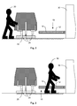
- An allowable object may be, for example, three struts 26 of a transport device 28.
- the object that is not allowed can be a human.
- the aforementioned at least three criteria (entrance area, size of the objects and distance or distances between the objects) and at least one of the additional criteria (each maximum and minimum object size, conveying speed or conveying direction) must be entered into the light grid 10.
- This can be done with the aid of configuration means that are connected, for example, with a PC with appropriate configuration software.
- the light grid 10 is placed in a teach-in mode (also called a teach-in mode) by passing the mentioned criteria when passing through the permitted object, eg. B. of the trolley 28, learns automatically.
- the control and evaluation unit 24 has a switching means 32, via which the teach-in mode can be initiated.
- the transport carriage 28 is then moved through the protective field in the transport direction 34 at the usual conveying speed.
- the entrance area here in Fig. 1 lowest photocell
- the number of struts or the order of struts, if they were distinguishable, could be learned.
- a minimum object size or a maximum conveying speed or a conveying direction is monitored for each individual object.
- the light grid 10 performs its protective function
- one of the criteria is not met, for example, when a human 30 enters with one leg in the middle of the protective field, the entrance area, ie the in Fig. 1 lowest Photocells, but is not interrupted, the associated criterion of the specified entry range is not met and issued the warning and / or the dangerous machine 36 or system off.
- the trolley 28, however, with its struts 26 first passes through the entrance area of the protective field, which is permitted and does not lead to a warning signal or shutdown. The same applies to the other criteria.
- the light grid can recognize that the thickness of the leg of the person 30 differs from the cross section of the struts 26.
- the distance a or b between two struts 26 is always constant, while changing the distance between the legs continuously when walking the person 30.
- FIG. 2 shows the arrangement FIG. 1 in the side view, wherein the struts 26 of the trolley have different widths.
- These taught minimum and maximum object sizes are monitored in the protective operation of the light grid 10, individually for each strut 26. Now occurs a different object size, for example by an incoming person 30, as in FIG. 3 shown, this leads directly to the issuing of a control signal.
- safety is further increased significantly. A manipulation of the light grid 10 is made considerably more difficult.
- the maximum conveying speed is monitored during protective operation.
- the maximum conveying speed is predetermined, for example, by the transport carriage 28. If interruptions now occur in the light grid 10 that exceed this maximum conveying speed, it can be assumed that these are impermissible objects, for example persons 30 entering them. Again, will give a control signal immediately.
- the material transport to a working machine is separately performed for supplying raw material and for discharging the processing material via respective conveyors having a conveying direction.
- the light grid 10 is adjusted so that the conveying direction in the light grid 10 is monitored successively by the interruption of the individual light barriers. Now object movements occur against this direction of conveyance, the objects are classified as inadmissible and issued a control signal.
- the light grid 10 is operated in a reduced resolution. If dolly be used, the struts 26 have a higher tolerance and thus vary the width of the struts 20 of dolly to dolly in a particular area, this could cause false shutdowns. To avoid this, the light grid 10 is operated in the reduced resolution. This means that the actual resolution of the light grid 10 is electronically reduced. For example, it is possible to operate a light grid 10 with an optical resolution of 20 mm in a resolution of 30 mm by not using individual light barriers for the evaluation. Small variations in the dimension of the struts 26 are tolerated by the light grid 10. This considerably increases the availability of the light grid 10 in such an application.
- an interruption of individual light barriers of the light grid 10 is tolerated.
- drooping fastener tapes each interrupting only a single beam of light, do not lead to the emission of a control signal and thus not to the deactivation of a dangerous movement.
- the availability of the light grid 10 is further increased significantly.
- a band stop signal input to the light grid.
- an output signal of a transport device which provides information about the transport movement or speed, connected.
- the objects on it must also move.
- a control signal is emitted solely on account of the unacceptable movement of the persons occurring.
- the tape stop signal may initially be a binary signal that transmits only the states 'transport running' or 'transport not running'.
- An applied dynamic band stop signal may in particular be a signal of an incremental encoder or position / speed sensor or a corresponding signal is provided by a controller.
Applications Claiming Priority (1)
| Application Number | Priority Date | Filing Date | Title |
|---|---|---|---|
| DE102007043557A DE102007043557A1 (de) | 2007-09-12 | 2007-09-12 | Objekterfassung und Lichtgitter |
Publications (2)
| Publication Number | Publication Date |
|---|---|
| EP2037297A1 true EP2037297A1 (fr) | 2009-03-18 |
| EP2037297B1 EP2037297B1 (fr) | 2011-03-09 |
Family
ID=40193522
Family Applications (1)
| Application Number | Title | Priority Date | Filing Date |
|---|---|---|---|
| EP08105053A Active EP2037297B1 (fr) | 2007-09-12 | 2008-08-15 | Détection d'objet et barrière lumineuse |
Country Status (3)
| Country | Link |
|---|---|
| EP (1) | EP2037297B1 (fr) |
| AT (1) | ATE501449T1 (fr) |
| DE (2) | DE102007043557A1 (fr) |
Cited By (5)
| Publication number | Priority date | Publication date | Assignee | Title |
|---|---|---|---|---|
| EP2306063A3 (fr) * | 2009-10-02 | 2012-12-05 | Leuze electronic GmbH + Co. KG | Capteur de sécurité |
| EP2975434A1 (fr) * | 2014-07-14 | 2016-01-20 | Omron Corporation | Capteur photo-électrique à multiple axes optiques |
| CN109879025A (zh) * | 2019-03-05 | 2019-06-14 | 威海新北洋技术服务有限公司 | 并排物体分离方法及装置 |
| WO2020126006A1 (fr) * | 2018-12-20 | 2020-06-25 | Sick Ag | Dispositif de capteurs pour la détection d'un objet cible influencé par un processus ou formé dans un processus |
| CN111508121A (zh) * | 2020-03-30 | 2020-08-07 | 北京龙德时代技术服务有限公司 | 可视化多色激光智能虚拟闸机控制系统 |
Families Citing this family (5)
| Publication number | Priority date | Publication date | Assignee | Title |
|---|---|---|---|---|
| DE102009031226B4 (de) * | 2009-07-01 | 2016-06-30 | Sick Ag | Sicherheitslichtgitter |
| DE102010037681B4 (de) * | 2010-09-21 | 2018-12-27 | Sick Ag | Lichtgitter und Verfahren zur Objektvermessung mit einem Lichtgitter |
| EP3002615B1 (fr) | 2014-10-03 | 2020-02-26 | Omron Corporation | Capteur et système de sécurité |
| DE202019103376U1 (de) * | 2019-06-17 | 2020-09-23 | Leuze Electronic Gmbh + Co. Kg | Vorrichtung |
| DE102022116110A1 (de) | 2021-06-28 | 2022-12-29 | Ileso GmbH & Co. KG | ESD-Kontrollanordnung |
Citations (6)
| Publication number | Priority date | Publication date | Assignee | Title |
|---|---|---|---|---|
| DE3803033A1 (de) | 1988-02-02 | 1989-08-10 | Sick Erwin Gmbh | Lichtschrankengitter |
| DE4424537A1 (de) | 1994-07-12 | 1996-01-18 | Sick Optik Elektronik Erwin | Verfahren zum Betrieb eines Lichtgitters und Lichtgitter |
| DE20103828U1 (de) | 2001-03-06 | 2001-06-13 | Fiessler Elektronik Ohg | Sicherheitseinrichtung zur Überwachung eines Durchgangs |
| EP1353196A1 (fr) * | 2002-04-12 | 2003-10-15 | Sick Ag | Détection d'un objet et barrière optique |
| DE102005038019A1 (de) * | 2005-08-09 | 2007-02-15 | Cedes Ag | Sensorvorrichtung zur Detektion eines Überhangs an der Beladung einer Trägereinrichtung |
| EP1785745A1 (fr) * | 2005-11-10 | 2007-05-16 | Omron Electronics Manufacturing of Germany GmbH | Procédé et unité de commande destinés à la configuration et à la surveillance d un dispositif muni d une sécurité fonctionnelle |
-
2007
- 2007-09-12 DE DE102007043557A patent/DE102007043557A1/de not_active Withdrawn
-
2008
- 2008-08-15 DE DE502008002793T patent/DE502008002793D1/de active Active
- 2008-08-15 EP EP08105053A patent/EP2037297B1/fr active Active
- 2008-08-15 AT AT08105053T patent/ATE501449T1/de active
Patent Citations (7)
| Publication number | Priority date | Publication date | Assignee | Title |
|---|---|---|---|---|
| DE3803033A1 (de) | 1988-02-02 | 1989-08-10 | Sick Erwin Gmbh | Lichtschrankengitter |
| DE4424537A1 (de) | 1994-07-12 | 1996-01-18 | Sick Optik Elektronik Erwin | Verfahren zum Betrieb eines Lichtgitters und Lichtgitter |
| DE20103828U1 (de) | 2001-03-06 | 2001-06-13 | Fiessler Elektronik Ohg | Sicherheitseinrichtung zur Überwachung eines Durchgangs |
| EP1353196A1 (fr) * | 2002-04-12 | 2003-10-15 | Sick Ag | Détection d'un objet et barrière optique |
| EP1353196B1 (fr) | 2002-04-12 | 2004-10-27 | Sick Ag | Détection d'un objet et barrière optique |
| DE102005038019A1 (de) * | 2005-08-09 | 2007-02-15 | Cedes Ag | Sensorvorrichtung zur Detektion eines Überhangs an der Beladung einer Trägereinrichtung |
| EP1785745A1 (fr) * | 2005-11-10 | 2007-05-16 | Omron Electronics Manufacturing of Germany GmbH | Procédé et unité de commande destinés à la configuration et à la surveillance d un dispositif muni d une sécurité fonctionnelle |
Cited By (11)
| Publication number | Priority date | Publication date | Assignee | Title |
|---|---|---|---|---|
| EP2306063A3 (fr) * | 2009-10-02 | 2012-12-05 | Leuze electronic GmbH + Co. KG | Capteur de sécurité |
| EP2306063B1 (fr) | 2009-10-02 | 2015-04-15 | Leuze electronic GmbH + Co. KG | Capteur de sécurité |
| EP2975434A1 (fr) * | 2014-07-14 | 2016-01-20 | Omron Corporation | Capteur photo-électrique à multiple axes optiques |
| CN105319606A (zh) * | 2014-07-14 | 2016-02-10 | 欧姆龙株式会社 | 多光轴光电传感器系统 |
| EP2975434B1 (fr) | 2014-07-14 | 2019-02-27 | Omron Corporation | Capteur photo-électrique à multiple axes optiques |
| WO2020126006A1 (fr) * | 2018-12-20 | 2020-06-25 | Sick Ag | Dispositif de capteurs pour la détection d'un objet cible influencé par un processus ou formé dans un processus |
| CN113424233A (zh) * | 2018-12-20 | 2021-09-21 | 西克股份公司 | 用于探测受过程影响或在该过程期间形成的目标物体的传感器设备 |
| US11747513B2 (en) | 2018-12-20 | 2023-09-05 | Sick Ag | Sensor apparatus |
| CN109879025A (zh) * | 2019-03-05 | 2019-06-14 | 威海新北洋技术服务有限公司 | 并排物体分离方法及装置 |
| CN109879025B (zh) * | 2019-03-05 | 2024-03-15 | 威海新北洋技术服务有限公司 | 并排物体分离方法及装置 |
| CN111508121A (zh) * | 2020-03-30 | 2020-08-07 | 北京龙德时代技术服务有限公司 | 可视化多色激光智能虚拟闸机控制系统 |
Also Published As
| Publication number | Publication date |
|---|---|
| EP2037297B1 (fr) | 2011-03-09 |
| DE502008002793D1 (de) | 2011-04-21 |
| DE102007043557A1 (de) | 2009-03-19 |
| ATE501449T1 (de) | 2011-03-15 |
Similar Documents
| Publication | Publication Date | Title |
|---|---|---|
| EP2037297B1 (fr) | Détection d'objet et barrière lumineuse | |
| EP1353196B1 (fr) | Détection d'un objet et barrière optique | |
| EP2180348B1 (fr) | Barrière lumineuse de sécurité et procédé correspondant de surveillance d'une zone de protection | |
| EP1873442B1 (fr) | Méthode et dispositif pour effectuer la surveillance de la sécurité d'un passage | |
| EP1089030B1 (fr) | Procédé et dispositif de contrôle d'une zone de protection | |
| DE102007033766B4 (de) | Lichtgitter | |
| DE102005030829C5 (de) | Verfahren zum Betrieb eines Lichtgitters und Lichtgitter | |
| EP1170601B1 (fr) | Grille de lumière | |
| EP3339715B1 (fr) | Système de protection d'accès | |
| DE102017112419B3 (de) | Zugangsabsicherungssystem | |
| DE102008004941A1 (de) | Sicherheitsanordnung und Verfahren | |
| EP2306063B2 (fr) | Capteur de sécurité | |
| DE102010017398B3 (de) | Verfahren zum Betrieb eines Tores sowie Vorrichtung zum Betrieb eines Tores | |
| EP3885635B1 (fr) | Dispositif de surveillance permettant de sécuriser l'accès à une zone dangereuse à l'aide d'un capteur de sécurité | |
| EP3293438B1 (fr) | Rideau lumineux de sécurité | |
| EP3415804B1 (fr) | Dispositif de sécurité | |
| DE202017103399U1 (de) | Zugangsabsicherungssystem | |
| EP3447540B1 (fr) | Rideau lumineux | |
| EP3594553A1 (fr) | Dispositif de surveillance d'une zone de danger | |
| EP3875993B1 (fr) | Dispositif capteur et procédé de fonctionnement d'un dispositif capteur | |
| EP3486545B1 (fr) | Commande de sécurité et système de sécurité | |
| EP4354010A1 (fr) | Dispositif de surveillance | |
| EP4137735A1 (fr) | Dispositif de surveillance et procédé de fonctionnement d'un systeme capteur | |
| DE202007009207U1 (de) | Lichtgitter |
Legal Events
| Date | Code | Title | Description |
|---|---|---|---|
| PUAI | Public reference made under article 153(3) epc to a published international application that has entered the european phase |
Free format text: ORIGINAL CODE: 0009012 |
|
| AK | Designated contracting states |
Kind code of ref document: A1 Designated state(s): AT BE BG CH CY CZ DE DK EE ES FI FR GB GR HR HU IE IS IT LI LT LU LV MC MT NL NO PL PT RO SE SI SK TR |
|
| AX | Request for extension of the european patent |
Extension state: AL BA MK RS |
|
| 17P | Request for examination filed |
Effective date: 20090831 |
|
| AKX | Designation fees paid |
Designated state(s): AT BE BG CH CY CZ DE DK EE ES FI FR GB GR HR HU IE IS IT LI LT LU LV MC MT NL NO PL PT RO SE SI SK TR |
|
| 17Q | First examination report despatched |
Effective date: 20100222 |
|
| GRAP | Despatch of communication of intention to grant a patent |
Free format text: ORIGINAL CODE: EPIDOSNIGR1 |
|
| GRAS | Grant fee paid |
Free format text: ORIGINAL CODE: EPIDOSNIGR3 |
|
| GRAA | (expected) grant |
Free format text: ORIGINAL CODE: 0009210 |
|
| AK | Designated contracting states |
Kind code of ref document: B1 Designated state(s): AT BE BG CH CY CZ DE DK EE ES FI FR GB GR HR HU IE IS IT LI LT LU LV MC MT NL NO PL PT RO SE SI SK TR |
|
| REG | Reference to a national code |
Ref country code: GB Ref legal event code: FG4D Free format text: NOT ENGLISH |
|
| REG | Reference to a national code |
Ref country code: CH Ref legal event code: EP |
|
| REG | Reference to a national code |
Ref country code: IE Ref legal event code: FG4D Free format text: LANGUAGE OF EP DOCUMENT: GERMAN |
|
| REF | Corresponds to: |
Ref document number: 502008002793 Country of ref document: DE Date of ref document: 20110421 Kind code of ref document: P |
|
| REG | Reference to a national code |
Ref country code: DE Ref legal event code: R096 Ref document number: 502008002793 Country of ref document: DE Effective date: 20110421 |
|
| REG | Reference to a national code |
Ref country code: NL Ref legal event code: VDEP Effective date: 20110309 |
|
| PG25 | Lapsed in a contracting state [announced via postgrant information from national office to epo] |
Ref country code: NO Free format text: LAPSE BECAUSE OF FAILURE TO SUBMIT A TRANSLATION OF THE DESCRIPTION OR TO PAY THE FEE WITHIN THE PRESCRIBED TIME-LIMIT Effective date: 20110609 Ref country code: LV Free format text: LAPSE BECAUSE OF FAILURE TO SUBMIT A TRANSLATION OF THE DESCRIPTION OR TO PAY THE FEE WITHIN THE PRESCRIBED TIME-LIMIT Effective date: 20110309 Ref country code: ES Free format text: LAPSE BECAUSE OF FAILURE TO SUBMIT A TRANSLATION OF THE DESCRIPTION OR TO PAY THE FEE WITHIN THE PRESCRIBED TIME-LIMIT Effective date: 20110620 Ref country code: GR Free format text: LAPSE BECAUSE OF FAILURE TO SUBMIT A TRANSLATION OF THE DESCRIPTION OR TO PAY THE FEE WITHIN THE PRESCRIBED TIME-LIMIT Effective date: 20110610 Ref country code: SE Free format text: LAPSE BECAUSE OF FAILURE TO SUBMIT A TRANSLATION OF THE DESCRIPTION OR TO PAY THE FEE WITHIN THE PRESCRIBED TIME-LIMIT Effective date: 20110309 Ref country code: LT Free format text: LAPSE BECAUSE OF FAILURE TO SUBMIT A TRANSLATION OF THE DESCRIPTION OR TO PAY THE FEE WITHIN THE PRESCRIBED TIME-LIMIT Effective date: 20110309 Ref country code: HR Free format text: LAPSE BECAUSE OF FAILURE TO SUBMIT A TRANSLATION OF THE DESCRIPTION OR TO PAY THE FEE WITHIN THE PRESCRIBED TIME-LIMIT Effective date: 20110309 |
|
| LTIE | Lt: invalidation of european patent or patent extension |
Effective date: 20110309 |
|
| PG25 | Lapsed in a contracting state [announced via postgrant information from national office to epo] |
Ref country code: BG Free format text: LAPSE BECAUSE OF FAILURE TO SUBMIT A TRANSLATION OF THE DESCRIPTION OR TO PAY THE FEE WITHIN THE PRESCRIBED TIME-LIMIT Effective date: 20110609 Ref country code: FI Free format text: LAPSE BECAUSE OF FAILURE TO SUBMIT A TRANSLATION OF THE DESCRIPTION OR TO PAY THE FEE WITHIN THE PRESCRIBED TIME-LIMIT Effective date: 20110309 Ref country code: CY Free format text: LAPSE BECAUSE OF FAILURE TO SUBMIT A TRANSLATION OF THE DESCRIPTION OR TO PAY THE FEE WITHIN THE PRESCRIBED TIME-LIMIT Effective date: 20110309 Ref country code: SI Free format text: LAPSE BECAUSE OF FAILURE TO SUBMIT A TRANSLATION OF THE DESCRIPTION OR TO PAY THE FEE WITHIN THE PRESCRIBED TIME-LIMIT Effective date: 20110309 Ref country code: NL Free format text: LAPSE BECAUSE OF FAILURE TO SUBMIT A TRANSLATION OF THE DESCRIPTION OR TO PAY THE FEE WITHIN THE PRESCRIBED TIME-LIMIT Effective date: 20110309 |
|
| REG | Reference to a national code |
Ref country code: IE Ref legal event code: FD4D |
|
| PG25 | Lapsed in a contracting state [announced via postgrant information from national office to epo] |
Ref country code: IE Free format text: LAPSE BECAUSE OF FAILURE TO SUBMIT A TRANSLATION OF THE DESCRIPTION OR TO PAY THE FEE WITHIN THE PRESCRIBED TIME-LIMIT Effective date: 20110309 Ref country code: EE Free format text: LAPSE BECAUSE OF FAILURE TO SUBMIT A TRANSLATION OF THE DESCRIPTION OR TO PAY THE FEE WITHIN THE PRESCRIBED TIME-LIMIT Effective date: 20110309 Ref country code: PT Free format text: LAPSE BECAUSE OF FAILURE TO SUBMIT A TRANSLATION OF THE DESCRIPTION OR TO PAY THE FEE WITHIN THE PRESCRIBED TIME-LIMIT Effective date: 20110711 |
|
| PG25 | Lapsed in a contracting state [announced via postgrant information from national office to epo] |
Ref country code: IS Free format text: LAPSE BECAUSE OF FAILURE TO SUBMIT A TRANSLATION OF THE DESCRIPTION OR TO PAY THE FEE WITHIN THE PRESCRIBED TIME-LIMIT Effective date: 20110709 Ref country code: CZ Free format text: LAPSE BECAUSE OF FAILURE TO SUBMIT A TRANSLATION OF THE DESCRIPTION OR TO PAY THE FEE WITHIN THE PRESCRIBED TIME-LIMIT Effective date: 20110309 Ref country code: RO Free format text: LAPSE BECAUSE OF FAILURE TO SUBMIT A TRANSLATION OF THE DESCRIPTION OR TO PAY THE FEE WITHIN THE PRESCRIBED TIME-LIMIT Effective date: 20110309 Ref country code: SK Free format text: LAPSE BECAUSE OF FAILURE TO SUBMIT A TRANSLATION OF THE DESCRIPTION OR TO PAY THE FEE WITHIN THE PRESCRIBED TIME-LIMIT Effective date: 20110309 |
|
| PG25 | Lapsed in a contracting state [announced via postgrant information from national office to epo] |
Ref country code: MT Free format text: LAPSE BECAUSE OF FAILURE TO SUBMIT A TRANSLATION OF THE DESCRIPTION OR TO PAY THE FEE WITHIN THE PRESCRIBED TIME-LIMIT Effective date: 20110309 |
|
| PLBE | No opposition filed within time limit |
Free format text: ORIGINAL CODE: 0009261 |
|
| STAA | Information on the status of an ep patent application or granted ep patent |
Free format text: STATUS: NO OPPOSITION FILED WITHIN TIME LIMIT |
|
| 26N | No opposition filed |
Effective date: 20111212 |
|
| BERE | Be: lapsed |
Owner name: SICK A.G. Effective date: 20110831 |
|
| PG25 | Lapsed in a contracting state [announced via postgrant information from national office to epo] |
Ref country code: DK Free format text: LAPSE BECAUSE OF FAILURE TO SUBMIT A TRANSLATION OF THE DESCRIPTION OR TO PAY THE FEE WITHIN THE PRESCRIBED TIME-LIMIT Effective date: 20110309 Ref country code: PL Free format text: LAPSE BECAUSE OF FAILURE TO SUBMIT A TRANSLATION OF THE DESCRIPTION OR TO PAY THE FEE WITHIN THE PRESCRIBED TIME-LIMIT Effective date: 20110309 |
|
| PG25 | Lapsed in a contracting state [announced via postgrant information from national office to epo] |
Ref country code: MC Free format text: LAPSE BECAUSE OF NON-PAYMENT OF DUE FEES Effective date: 20110831 |
|
| REG | Reference to a national code |
Ref country code: DE Ref legal event code: R097 Ref document number: 502008002793 Country of ref document: DE Effective date: 20111212 |
|
| PG25 | Lapsed in a contracting state [announced via postgrant information from national office to epo] |
Ref country code: BE Free format text: LAPSE BECAUSE OF NON-PAYMENT OF DUE FEES Effective date: 20110831 |
|
| GBPC | Gb: european patent ceased through non-payment of renewal fee |
Effective date: 20120815 |
|
| PG25 | Lapsed in a contracting state [announced via postgrant information from national office to epo] |
Ref country code: LU Free format text: LAPSE BECAUSE OF NON-PAYMENT OF DUE FEES Effective date: 20110815 |
|
| PG25 | Lapsed in a contracting state [announced via postgrant information from national office to epo] |
Ref country code: GB Free format text: LAPSE BECAUSE OF NON-PAYMENT OF DUE FEES Effective date: 20120815 |
|
| PG25 | Lapsed in a contracting state [announced via postgrant information from national office to epo] |
Ref country code: TR Free format text: LAPSE BECAUSE OF FAILURE TO SUBMIT A TRANSLATION OF THE DESCRIPTION OR TO PAY THE FEE WITHIN THE PRESCRIBED TIME-LIMIT Effective date: 20110309 |
|
| PG25 | Lapsed in a contracting state [announced via postgrant information from national office to epo] |
Ref country code: HU Free format text: LAPSE BECAUSE OF FAILURE TO SUBMIT A TRANSLATION OF THE DESCRIPTION OR TO PAY THE FEE WITHIN THE PRESCRIBED TIME-LIMIT Effective date: 20110309 |
|
| REG | Reference to a national code |
Ref country code: AT Ref legal event code: MM01 Ref document number: 501449 Country of ref document: AT Kind code of ref document: T Effective date: 20130815 |
|
| PG25 | Lapsed in a contracting state [announced via postgrant information from national office to epo] |
Ref country code: AT Free format text: LAPSE BECAUSE OF NON-PAYMENT OF DUE FEES Effective date: 20130815 |
|
| REG | Reference to a national code |
Ref country code: FR Ref legal event code: PLFP Year of fee payment: 8 |
|
| PGFP | Annual fee paid to national office [announced via postgrant information from national office to epo] |
Ref country code: FR Payment date: 20150824 Year of fee payment: 8 |
|
| REG | Reference to a national code |
Ref country code: FR Ref legal event code: ST Effective date: 20170428 |
|
| PG25 | Lapsed in a contracting state [announced via postgrant information from national office to epo] |
Ref country code: FR Free format text: LAPSE BECAUSE OF NON-PAYMENT OF DUE FEES Effective date: 20160831 |
|
| PGFP | Annual fee paid to national office [announced via postgrant information from national office to epo] |
Ref country code: CH Payment date: 20190826 Year of fee payment: 12 |
|
| PGFP | Annual fee paid to national office [announced via postgrant information from national office to epo] |
Ref country code: IT Payment date: 20200831 Year of fee payment: 13 |
|
| REG | Reference to a national code |
Ref country code: CH Ref legal event code: PL |
|
| PG25 | Lapsed in a contracting state [announced via postgrant information from national office to epo] |
Ref country code: LI Free format text: LAPSE BECAUSE OF NON-PAYMENT OF DUE FEES Effective date: 20200831 Ref country code: CH Free format text: LAPSE BECAUSE OF NON-PAYMENT OF DUE FEES Effective date: 20200831 |
|
| PG25 | Lapsed in a contracting state [announced via postgrant information from national office to epo] |
Ref country code: IT Free format text: LAPSE BECAUSE OF NON-PAYMENT OF DUE FEES Effective date: 20210815 |
|
| PGFP | Annual fee paid to national office [announced via postgrant information from national office to epo] |
Ref country code: DE Payment date: 20230822 Year of fee payment: 16 |