EP2037131A1 - Hybrid component - Google Patents
Hybrid component Download PDFInfo
- Publication number
- EP2037131A1 EP2037131A1 EP08016003A EP08016003A EP2037131A1 EP 2037131 A1 EP2037131 A1 EP 2037131A1 EP 08016003 A EP08016003 A EP 08016003A EP 08016003 A EP08016003 A EP 08016003A EP 2037131 A1 EP2037131 A1 EP 2037131A1
- Authority
- EP
- European Patent Office
- Prior art keywords
- component
- hybrid
- functional
- foot
- blind rivet
- Prior art date
- Legal status (The legal status is an assumption and is not a legal conclusion. Google has not performed a legal analysis and makes no representation as to the accuracy of the status listed.)
- Granted
Links
- 239000002184 metal Substances 0.000 claims abstract description 4
- 238000007789 sealing Methods 0.000 claims abstract description 4
- 238000010276 construction Methods 0.000 claims description 8
- 238000004873 anchoring Methods 0.000 claims description 5
- 238000013519 translation Methods 0.000 claims description 2
- 238000004026 adhesive bonding Methods 0.000 claims 1
- 238000007765 extrusion coating Methods 0.000 claims 1
- 235000001674 Agaricus brunnescens Nutrition 0.000 description 3
- 238000006073 displacement reaction Methods 0.000 description 3
- 239000006096 absorbing agent Substances 0.000 description 2
- 230000008878 coupling Effects 0.000 description 2
- 238000010168 coupling process Methods 0.000 description 2
- 238000005859 coupling reaction Methods 0.000 description 2
- 238000013461 design Methods 0.000 description 2
- 238000009434 installation Methods 0.000 description 2
- 230000035939 shock Effects 0.000 description 2
- 238000013459 approach Methods 0.000 description 1
- 238000011161 development Methods 0.000 description 1
- 230000018109 developmental process Effects 0.000 description 1
- 238000001746 injection moulding Methods 0.000 description 1
- 238000004519 manufacturing process Methods 0.000 description 1
- 230000000717 retained effect Effects 0.000 description 1
- 238000007493 shaping process Methods 0.000 description 1
- 239000000126 substance Substances 0.000 description 1
Images


Classifications
-
- F—MECHANICAL ENGINEERING; LIGHTING; HEATING; WEAPONS; BLASTING
- F16—ENGINEERING ELEMENTS AND UNITS; GENERAL MEASURES FOR PRODUCING AND MAINTAINING EFFECTIVE FUNCTIONING OF MACHINES OR INSTALLATIONS; THERMAL INSULATION IN GENERAL
- F16B—DEVICES FOR FASTENING OR SECURING CONSTRUCTIONAL ELEMENTS OR MACHINE PARTS TOGETHER, e.g. NAILS, BOLTS, CIRCLIPS, CLAMPS, CLIPS OR WEDGES; JOINTS OR JOINTING
- F16B19/00—Bolts without screw-thread; Pins, including deformable elements; Rivets
- F16B19/04—Rivets; Spigots or the like fastened by riveting
- F16B19/08—Hollow rivets; Multi-part rivets
- F16B19/10—Hollow rivets; Multi-part rivets fastened by expanding mechanically
- F16B19/1027—Multi-part rivets
- F16B19/1036—Blind rivets
- F16B19/1045—Blind rivets fastened by a pull - mandrel or the like
- F16B19/1072—Blind rivets fastened by a pull - mandrel or the like the pull-mandrel or the like comprising a thread and being rotated with respect to the rivet, thereby mechanically expanding and fastening the rivet
-
- B—PERFORMING OPERATIONS; TRANSPORTING
- B29—WORKING OF PLASTICS; WORKING OF SUBSTANCES IN A PLASTIC STATE IN GENERAL
- B29C—SHAPING OR JOINING OF PLASTICS; SHAPING OF MATERIAL IN A PLASTIC STATE, NOT OTHERWISE PROVIDED FOR; AFTER-TREATMENT OF THE SHAPED PRODUCTS, e.g. REPAIRING
- B29C45/00—Injection moulding, i.e. forcing the required volume of moulding material through a nozzle into a closed mould; Apparatus therefor
- B29C45/14—Injection moulding, i.e. forcing the required volume of moulding material through a nozzle into a closed mould; Apparatus therefor incorporating preformed parts or layers, e.g. injection moulding around inserts or for coating articles
- B29C45/14336—Coating a portion of the article, e.g. the edge of the article
-
- B—PERFORMING OPERATIONS; TRANSPORTING
- B60—VEHICLES IN GENERAL
- B60R—VEHICLES, VEHICLE FITTINGS, OR VEHICLE PARTS, NOT OTHERWISE PROVIDED FOR
- B60R13/00—Elements for body-finishing, identifying, or decorating; Arrangements or adaptations for advertising purposes
- B60R13/02—Internal Trim mouldings ; Internal Ledges; Wall liners for passenger compartments; Roof liners
- B60R13/0206—Arrangements of fasteners and clips specially adapted for attaching inner vehicle liners or mouldings
-
- B—PERFORMING OPERATIONS; TRANSPORTING
- B29—WORKING OF PLASTICS; WORKING OF SUBSTANCES IN A PLASTIC STATE IN GENERAL
- B29C—SHAPING OR JOINING OF PLASTICS; SHAPING OF MATERIAL IN A PLASTIC STATE, NOT OTHERWISE PROVIDED FOR; AFTER-TREATMENT OF THE SHAPED PRODUCTS, e.g. REPAIRING
- B29C45/00—Injection moulding, i.e. forcing the required volume of moulding material through a nozzle into a closed mould; Apparatus therefor
- B29C45/14—Injection moulding, i.e. forcing the required volume of moulding material through a nozzle into a closed mould; Apparatus therefor incorporating preformed parts or layers, e.g. injection moulding around inserts or for coating articles
- B29C45/14598—Coating tubular articles
-
- B—PERFORMING OPERATIONS; TRANSPORTING
- B29—WORKING OF PLASTICS; WORKING OF SUBSTANCES IN A PLASTIC STATE IN GENERAL
- B29K—INDEXING SCHEME ASSOCIATED WITH SUBCLASSES B29B, B29C OR B29D, RELATING TO MOULDING MATERIALS OR TO MATERIALS FOR MOULDS, REINFORCEMENTS, FILLERS OR PREFORMED PARTS, e.g. INSERTS
- B29K2705/00—Use of metals, their alloys or their compounds, for preformed parts, e.g. for inserts
-
- B—PERFORMING OPERATIONS; TRANSPORTING
- B60—VEHICLES IN GENERAL
- B60R—VEHICLES, VEHICLE FITTINGS, OR VEHICLE PARTS, NOT OTHERWISE PROVIDED FOR
- B60R13/00—Elements for body-finishing, identifying, or decorating; Arrangements or adaptations for advertising purposes
- B60R13/08—Insulating elements, e.g. for sound insulation
-
- Y—GENERAL TAGGING OF NEW TECHNOLOGICAL DEVELOPMENTS; GENERAL TAGGING OF CROSS-SECTIONAL TECHNOLOGIES SPANNING OVER SEVERAL SECTIONS OF THE IPC; TECHNICAL SUBJECTS COVERED BY FORMER USPC CROSS-REFERENCE ART COLLECTIONS [XRACs] AND DIGESTS
- Y10—TECHNICAL SUBJECTS COVERED BY FORMER USPC
- Y10S—TECHNICAL SUBJECTS COVERED BY FORMER USPC CROSS-REFERENCE ART COLLECTIONS [XRACs] AND DIGESTS
- Y10S411/00—Expanded, threaded, driven, headed, tool-deformed, or locked-threaded fastener
- Y10S411/90—Fastener or fastener element composed of plural different materials
- Y10S411/901—Core and exterior of different materials
- Y10S411/902—Metal core
- Y10S411/903—Resinous exterior
-
- Y—GENERAL TAGGING OF NEW TECHNOLOGICAL DEVELOPMENTS; GENERAL TAGGING OF CROSS-SECTIONAL TECHNOLOGIES SPANNING OVER SEVERAL SECTIONS OF THE IPC; TECHNICAL SUBJECTS COVERED BY FORMER USPC CROSS-REFERENCE ART COLLECTIONS [XRACs] AND DIGESTS
- Y10—TECHNICAL SUBJECTS COVERED BY FORMER USPC
- Y10T—TECHNICAL SUBJECTS COVERED BY FORMER US CLASSIFICATION
- Y10T403/00—Joints and connections
- Y10T403/70—Interfitted members
- Y10T403/7075—Interfitted members including discrete retainer
Definitions
- the present invention relates to a hybrid component for fastening functional elements, in particular in the motor vehicle.
- plastic fasteners which serve for coupling or attachment of components to structural components.
- One field of application is, for example, the motor vehicle construction, in which the body or the frame of the motor vehicle represents such a structural component.
- covers or panels are mounted in the engine compartment or in the interior of the motor vehicle. Due to the resilience of the plastic, the attachment of these components is not rigid. Therefore, for example, vibrations in the motor vehicle can lead to a loosening of the parts and thus to a shortened service life or a faster wear.
- the hybrid component according to the invention has the following features: a component foot comprising a metal rivet construction with which the hybrid component can be rigidly fastened to a structural component, a fastening lug connected to the component foot and comprising a fastening contour for a functional component, while the functional component comprises Plastic consists and is connected to the attachment lug, so that a component can be coupled to the structural component via the functional component and the component foot.
- the hybrid component according to the invention provides a high-strength connection possibility for further parts, for example in the motor vehicle.
- the basis of the hybrid component is a blind rivet construction which provides a stable connection with, for example, the frame or the body of the motor vehicle.
- the Blindnietkonstrutation thus provides a rigid foundation for the existing plastic functional component.
- the functional component is in turn the coupling member to a component to be fastened.
- Such components to be fastened include bumpers, covers, panels, to name but a few examples from the automotive industry.
- the component foot is formed by a blind rivet nut or a blind rivet.
- the component foot comprises a fastening lug, which is integrally connected to the component foot. This attachment lug is formed with a fastening contour, on the basis of which a rotationally secure and / or axially immovable anchoring of the functional component on the component foot can be realized.
- the fastening contour comprises a cylindrical region with a radially outward knurling, which forms an undercut against rotation and / or axial translation.
- the fastening contour has an embossment produced by cold forming.
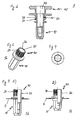
- the FIGS. 1A to C show various examples of the hybrid component according to the invention 1.
- the hybrid component 1 each comprises a component base 10. This consists of a rivet, for example, similar to a blind rivet nut or a Becher-Dichtblindniets. Since the component foot is made of metal and can be fastened to a structural component 5, the entire hybrid component 1 can likewise be rigidly fastened to the structural component 5, for example a frame of a motor vehicle.
- the hybrid component 1 also includes a mounting lug 20.
- This mounting lug 20 is integrally connected to the component foot 10 and the rivet construction.
- the attachment lug 20 serves to fasten a functional component 40 made of plastic to the component foot 10.
- the functional component 40 is, for example, a plate or mushroom head according to FIG Fig. 1A , a holder for a shock absorber according to Fig. 1B or a ball head according to Fig. 1C ,
- the functional component 40 is already firmly connected to the fastening lug 20 in a structural component 5 prior to riveting of the component foot 10.
- the functional component 40 comprises a through opening 42.
- the opening 42 ensures a passage through the functional component 40 to a blind rivet nut 12 with a threaded mandrel (not shown) or a Becher-Dichtblindniet using a rivet mandrel 16 (cf. FIGS. 10 to 12 ) to fix easily.
- the hybrid component 1 establishes a rigid or high-strength connection with the structural component 5, while the advantages of the plastic for the fastener are retained via the functional component 40 made of plastic.
- These advantages include the variability in the shaping by injection molding, a certain flexibility depending on the type of plastic, the low weight and the chemical and mechanical resistance at the same time limited costs for the hybrid component 1.
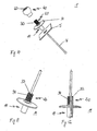
- FIGS. 2 to 12 show detailed illustrations of the preferred embodiments of the hybrid component 1 from Fig. 1A to C
- Fig. 2 shows a hybrid component 1 in section consisting of a blind rivet nut 12 as a component foot 10 and the functional component 40 in the form of a mushroom head.
- the attachment lug 20 is integrally formed on the blind rivet nut 12.
- This fastening lug 20 comprises an outer fastening contour 30 in order to hold the functional component 40 on the component foot 10.
- the fastening contour 30 provides a suitable structure for injecting and reliably anchoring the plastic functional component 40 thereto.
- the anchoring prevents a displacement of the functional component 40 in the direction of the longitudinal axis of the blind rivet nut 12.
- the anchoring also represents an anti-rotation, so that the functional component 40 can not be rotated about the longitudinal axis of the blind rivet 12.
- the fastening contour 30 comprises a cylindrical region 32, on the radial outer side of which a knurling 34 is provided.
- the knurling 34 preferably provides an undercut which prevents the functional component 40 from rotating about the longitudinal axis of the blind rivet nut 12.
- the knurling 34 additionally or alone provides an undercut against axial displacement of the functional component 40 in the direction of the longitudinal axis of the blind rivet nut 12.
- the fastening contour 30 comprises an embossment 36 produced by cold forming FIGS. 7 and 8 illustrated.
- the fastening contour 30 thus provides a positive and / or non-positive connection between the blind rivet construction and the functional component 40 ready. On this structural basis, a rotation and / or displacement of the functional component 40 with respect to the longitudinal axis of the rivet construction is prevented.
- the component foot 10 has a polygonal cross-sectional shape, such as a hexagon.
- a polygonal cross-sectional shape such as a hexagon.
- Fig. 4 shown in a plan view of the rivet shank of the blind rivet nut Fig. 3 is shown. If this hexagon is inserted into an adapted opening of the structural component 5, for example a hexagonal opening, a predetermined positioning is possible before the hybrid component 1 is fastened. This VorPosition réelle supports the later installation of the component in the motor vehicle and provides a further rotation of the hybrid component. 1
- FIG. 5 includes a cylindrical portion 32 with the knurling 34
- Fig. 9 shows the stamp 36, which is provided on the cylindrical portion 32.
- Fig. 6 shows a sectional view of a hybrid component 1, which also has the blind rivet nut 12 as a component foot 10.
- a functional component 40 about the embossment 36 on the attachment lug 20 is attached as a functional component 40, a lever structure. This serves for the later attachment of shock absorbers in the motor vehicle.
- Fig. 10 shows a hybrid component 1 with a ball head as a functional component 40 in an exploded view.
- the ball head 40 with continuous opening 42 is mounted on the mounting lug 20 with fastening contour 30.
- the attachment lug 20 in turn is integrally formed on the cup sealing blind rivet 14.
- the embodiments of the FIGS. 11 and 12 comprise, for example, the cylindrical region 32 with knurling 34.
- the cup sealing blind rivet 14 is fastened in a known manner to the structural component 5 via a rivet mandrel 16, so that the hybrid component 1 fixed in this way serves to couple further components to the structural component 5.
Abstract
Description
Die vorliegende Erfindung betrifft ein Hybridbauteil zur Befestigung von Funktionselementen, insbesondere im Kraftfahrzeug.The present invention relates to a hybrid component for fastening functional elements, in particular in the motor vehicle.
Im Stand der Technik sind Kunststoff-Befestiger bekannt, die zur Kopplung bzw. Befestigung von Komponenten an Strukturbauteilen dienen. Ein Anwendungsgebiet ist zum Beispiel der Kraftfahrzeugbau, in dem die Karosse oder der Rahmen des Kraftfahrzeugs ein derartiges Strukturbauteil darstellt. Mit Hilfe dieser Kunststoff-Befestiger werden unter anderem Abdeckungen oder Verkleidungen im Motorraum oder im Innenraum des Kraftfahrzeugs angebracht. Aufgrund der Nachgiebigkeit des Kunststoffs ist die Befestigung dieser Komponenten nicht starr. Daher können beispielsweise Vibrationen im Kraftfahrzeug zu einer Lockerung der Teile und somit zu einer verkürzten Lebensdauer oder einem schnelleren Verschleiß führen.In the prior art plastic fasteners are known which serve for coupling or attachment of components to structural components. One field of application is, for example, the motor vehicle construction, in which the body or the frame of the motor vehicle represents such a structural component. With the help of these plastic fasteners, inter alia, covers or panels are mounted in the engine compartment or in the interior of the motor vehicle. Due to the resilience of the plastic, the attachment of these components is not rigid. Therefore, for example, vibrations in the motor vehicle can lead to a loosening of the parts and thus to a shortened service life or a faster wear.
Es ist daher die Aufgabe der vorliegenden Erfindung, im Vergleich zum Stand der Technik eine stabilere Verbindung bereitzustellen, mit der beispielsweise im Kraftfahrzeugbau Komponenten einfach und dauerhaft an Strukturbauteilen befestigbar sind.It is therefore the object of the present invention, in comparison to the prior art to provide a more stable connection, with which, for example, in motor vehicle components can be easily and permanently attached to structural components.
Die oben genannte Aufgabe wird durch ein Hybridbauteil gemäß dem unabhängigen Patentanspruch 1 sowie durch ein Strukturbauteil mit Hybridbauteil gemäß dem unabhängigen Patentanspruch 9 gelöst. Vorteilhafte Ausfiihrungsformen und Weiterentwicklungen der Erfindung gehen aus der folgenden Beschreibung, den begleitenden Zeichnungen sowie den anhängenden Ansprüchen hervor.The above object is achieved by a hybrid component according to the
Das erfindungsgemäße Hybridbauteil weist die folgenden Merkmale auf: einen Bauteilfuß bestehend aus einer Blindnietkonstruktion aus Metall, mit dem das Hybridbauteil starr an einem Strukturbauteil befestigbar ist, einen Befestigungsansatz, der mit dem Bauteilfuß verbunden ist und eine Befestigungskontur für eine Funktionskomponente umfasst, während die Funktionskomponente aus Kunststoff besteht und mit dem Befestigungsansatz verbunden ist, so dass über die Funktionskomponente und den Bauteilfuß eine Komponente an das Strukturbauteil koppelbar ist.The hybrid component according to the invention has the following features: a component foot comprising a metal rivet construction with which the hybrid component can be rigidly fastened to a structural component, a fastening lug connected to the component foot and comprising a fastening contour for a functional component, while the functional component comprises Plastic consists and is connected to the attachment lug, so that a component can be coupled to the structural component via the functional component and the component foot.
Das erfindungsgemäße Hybridbauteil liefert eine hochfeste Anbindungsmöglichkeit für weitere Teile, beispielsweise im Kraftfahrzeug. Als Basis des Hybridbauteils dient eine Blindnietkonstruktion, die eine stabile Verbindung mit beispielsweise dem Rahmen oder der Karosserie des Kraftfahrzeugs bereitstellt. Die Blindnietkonstruktion liefert somit ein starres Fundament für die aus Kunststoff bestehende Funktionskomponente. Die Funktionskomponente ist wiederum das Kopplungsglied zu einer zu befestigenden Komponente. Derartige zu befestigende Komponenten umfassen Stoßfänger, Abdeckungen, Verkleidungen, um nur einige Beispiele aus der Automobilbranche zu nennen.The hybrid component according to the invention provides a high-strength connection possibility for further parts, for example in the motor vehicle. The basis of the hybrid component is a blind rivet construction which provides a stable connection with, for example, the frame or the body of the motor vehicle. The Blindnietkonstruktion thus provides a rigid foundation for the existing plastic functional component. The functional component is in turn the coupling member to a component to be fastened. Such components to be fastened include bumpers, covers, panels, to name but a few examples from the automotive industry.
Gemäß einer Ausführungsform der vorliegenden Erfindung wird der Bauteilfuß durch eine Blindnietmutter oder einen Blindniet gebildet. In weiterer Ausgestaltung umfasst der Bauteilfuß einen Befestigungsansatz, der integral mit dem Bauteilfuß verbunden ist. Dieser Befestigungsansatz ist mit einer Befestigungskontur ausgebildet, auf deren Grundlage eine verdrehsichere und/oder axial unverschiebbare Verankerung der Funktionskomponente am Bauteilfuß realisierbar ist.According to one embodiment of the present invention, the component foot is formed by a blind rivet nut or a blind rivet. In a further embodiment, the component foot comprises a fastening lug, which is integrally connected to the component foot. This attachment lug is formed with a fastening contour, on the basis of which a rotationally secure and / or axially immovable anchoring of the functional component on the component foot can be realized.
Da der Befestigungsansatz durch seine Form die Grundlage für eine form- und/oder kraftschlüssige Verbindung zwischen Bauteilfuß und Funktionskomponente bildet, sind verschiedene Ausführungsformen der Befestigungskontur bevorzugt. Gemäß einer Alternative umfasst die Befestigungskontur einen zylindrischen Bereich mit einer radial außen liegenden Rändelung, die einen Hinterschnitt gegen Rotation und/oder axiale Translation bildet. Gemäß einer weiteren Alternative weist die Befestigungskontur eine durch Kaltumformung erzeugte Verprägung auf.Since the attachment approach forms the basis for a positive and / or non-positive connection between the component foot and functional component by its shape, various embodiments of the fastening contour are preferred. According to an alternative, the fastening contour comprises a cylindrical region with a radially outward knurling, which forms an undercut against rotation and / or axial translation. According to a further alternative, the fastening contour has an embossment produced by cold forming.
Die vorliegende Erfindung wird unter Bezugnahme auf die begleitende Zeichnung näher erläutert. Es zeigen:
- Fig. 1A bis C
- verschiedene Ausführungsformen des Hybridbauteils in perspektivi- scher oder Schnittansicht,
- Fig. 2
- eine Schnittdarstellung einer Ausführungsform des Hybridbauteils bestehend aus Blindnietmutter und Pilzkopf,
- Fig. 3
- eine perspektivische Darstellung einer Blindnietmutter aus der Aus- führungsform gemäß
Fig. 2 , - Fig. 4
- eine Draufsicht auf den Nietschaft der Blindnietmutter gemäß
Fig. 3 , - Fig. 5A, B
- eine teilweise Schnittdarstellung der Blindnietmutter aus
Fig. 3 im unbefestigten (A) und im befestigten Zustand (B) in einem Struktur- bauteil, - Fig. 6
- eine Schnittdarstellung der Ausführungsform des Hybridbauteils gemäß
Fig. 1 B , - Fig. 7
- eine perspektivische Ansicht der Blindnietmutter aus
Fig. 6 , - Fig. 8
- eine axiale Draufsicht auf den Befestigungsansatz der Blindnietmut- ter aus
Fig. 7 , - Fig. 9A, B
- die Blindnietmutter aus
Fig. 7 im unbefestigten (A) und im befestig- ten Zustand (B) in einem Strukturbauteil, - Fig. 10
- eine Explosionsdarstellung der Ausführungsform des Hybridbauteils gemäß
Fig. 1C , - Fig. 11
- eine perspektivische Darstellung des Becherblindniets aus
Fig. 10 und - Fig. 12
- eine teilweise Schnittdarstellung des Becherblindniets aus
Fig. 10 .
- Fig. 1A to C
- various embodiments of the hybrid component in perspective or sectional view,
- Fig. 2
- a sectional view of an embodiment of the hybrid component consisting of blind rivet nut and mushroom head,
- Fig. 3
- a perspective view of a blind rivet nut according to the embodiment according to
Fig. 2 . - Fig. 4
- a plan view of the rivet shank of the blind rivet nut according to
Fig. 3 . - Fig. 5A, B
- a partial sectional view of the blind rivet nut
Fig. 3 in the unattached (A) and in the fixed state (B) in a structural component, - Fig. 6
- a sectional view of the embodiment of the hybrid component according to
Fig. 1 B . - Fig. 7
- a perspective view of the blind rivet nut
Fig. 6 . - Fig. 8
- an axial plan view of the attachment lug of Blindnietmut- ter
Fig. 7 . - Fig. 9A, B
- the blind rivet nut
Fig. 7 in the unattached (A) and in the fastened state (B) in a structural component, - Fig. 10
- an exploded view of the embodiment of the hybrid component according to
Fig. 1C . - Fig. 11
- a perspective view of Becherblindniets
Fig. 10 and - Fig. 12
- a partial sectional view of the Becherblindniets
Fig. 10 ,
Die
Das Hybridbauteil 1 umfasst zudem einen Befestigungsansatz 20. Dieser Befestigungsansatz 20 ist integral mit dem Bauteilfuß 10 bzw. der Nietkonstruktion verbunden. Der Befestigungsansatz 20 dient dem Befestigen einer Funktionskomponente 40 aus Kunststoff am Bauteilfuß 10. Die Funktionskomponente 40 ist beispielsweise ein Teller- oder Pilzkopf gemäß
Mit der vorliegenden Erfindung ist man in der Lage, beispielsweise in der Endmontage von Kraftfahrzeugen, das Hybridbauteil 1 als angepassten Befestiger mit nur einem Arbeitsschritt an einem Strukturbauteil 5 von Karosserie oder Rahmen eines Kraftfahrzeugs befestigen zu können. Das Hybridbauteil 1 stellt eine starre bzw. hochfeste Verbindung mit dem Strukturbauteil 5 her, während über die Funktionskomponente 40 aus Kunststoff die Vorteile des Kunststoffs für den Befestiger erhalten bleiben. Zu diesen Vorteilen zählen die Variabilität in der Formgebung durch Spritzverfahren, eine gewisse Flexibilität je nach Kunststoffart, das geringe Gewicht sowie die chemische und mechanische Beständigkeit bei gleichzeitig begrenzten Kosten für das Hybridbauteil 1. Im Vergleich zum Stand der Technik ist es daher nicht erforderlich, zunächst eine Blindnietmutter oder Schweißmutter zu setzen und darin einen Bolzen mit Funktionsabschnitt einzuschrauben. Dies spart Zeit und Aufwand im Fertigungsprozess, da das Hybridbauteil 1 mit nur einem Arbeitsschritt installierbar ist.With the present invention, it is possible, for example in the final assembly of motor vehicles, to be able to fasten the
Die
Gemäß einer Ausführungsform des Hybridbauteils 1 umfasst die Befestigungskontur 30 einen zylindrischen Bereich 32, an dessen radialer Außenseite eine Rändelung 34 vorgesehen ist. Diese Konstruktion ist in
Gemäß einer weiteren Ausführungsform des Hybridbauteils 1 umfasst die Befestigungskontur 30 eine durch Kaltumformung erzeugte Verprägung 36. Diese ist in den
Allgemein stellt die Befestigungskontur 30 somit eine formschlüssige und/oder kraftschlüssige Verbindung zwischen der Blindnietkonstruktion und der Funktionskomponente 40 bereit. Auf dieser konstruktiven Grundlage ist ein Verdrehen und/oder Versetzen der Funktionskomponente 40 bezogen auf die Längsachse der Nietkonstruktion verhindert.In general, the
Gemäß einer weiteren Ausführungsform weist der Bauteilfuß 10 eine polygonale Querschnittsform auf, wie beispielsweise einen Sechskant. Eine derartige Formgestaltung ist in
In den
Claims (9)
Applications Claiming Priority (1)
| Application Number | Priority Date | Filing Date | Title |
|---|---|---|---|
| DE202007012797U DE202007012797U1 (en) | 2007-09-12 | 2007-09-12 | hybrid component |
Publications (2)
| Publication Number | Publication Date |
|---|---|
| EP2037131A1 true EP2037131A1 (en) | 2009-03-18 |
| EP2037131B1 EP2037131B1 (en) | 2011-03-16 |
Family
ID=38721684
Family Applications (1)
| Application Number | Title | Priority Date | Filing Date |
|---|---|---|---|
| EP08016003A Active EP2037131B1 (en) | 2007-09-12 | 2008-09-11 | Hybrid component |
Country Status (4)
| Country | Link |
|---|---|
| US (1) | US7841816B2 (en) |
| EP (1) | EP2037131B1 (en) |
| AT (1) | ATE502220T1 (en) |
| DE (2) | DE202007012797U1 (en) |
Cited By (1)
| Publication number | Priority date | Publication date | Assignee | Title |
|---|---|---|---|---|
| CN102094883A (en) * | 2011-02-22 | 2011-06-15 | 苏州工业园区新凯精密五金有限公司 | Press-riveting nut column |
Families Citing this family (10)
| Publication number | Priority date | Publication date | Assignee | Title |
|---|---|---|---|---|
| US8292560B2 (en) * | 2008-10-23 | 2012-10-23 | Avk Industrial Products | Anchor device with double-sectioned head and method of using the same |
| FR2963576B1 (en) * | 2010-08-05 | 2012-09-07 | Bollhoff Otalu Sa | SPHERICAL MEMBER DEVICE FOR CRIMPING AND CRIMPING METHOD |
| CN102003449A (en) * | 2010-12-01 | 2011-04-06 | 苏州工业园区新凯精密五金有限公司 | Riveting clamp post nut |
| DE102012219008A1 (en) * | 2012-10-18 | 2014-04-24 | Bayerische Motoren Werke Aktiengesellschaft | Blind rivet and component connection with a blind rivet |
| FR3032246B1 (en) * | 2015-01-30 | 2017-08-04 | Bollhoff Otalu Sa | CRIMP NUT AND FIXING ASSEMBLY COMPRISING SUCH NUT |
| JP2018013151A (en) * | 2016-07-20 | 2018-01-25 | ポップリベット・ファスナー株式会社 | Blind nut, blind nut assembly, and fastening structure |
| US10794415B2 (en) * | 2017-06-30 | 2020-10-06 | Bollhoff Inc. | Threaded blind fastener and spacer assembly and methods for the assembly and use thereof |
| DE102018111049A1 (en) * | 2018-05-08 | 2019-11-14 | Böllhoff Verbindungstechnik GmbH | CONNECTION BETWEEN TWO TOLERANCE COMPONENT COMPONENTS AND A CONNECTING METHOD THEREFOR |
| US11365754B2 (en) * | 2019-04-18 | 2022-06-21 | Ami Industries, Inc. | Detachable fastener assembly |
| DE102021106103A1 (en) | 2021-03-12 | 2022-09-15 | Profil Verbindungstechnik Gmbh & Co. Kg | functional element |
Citations (5)
| Publication number | Priority date | Publication date | Assignee | Title |
|---|---|---|---|---|
| GB1354351A (en) * | 1971-05-18 | 1974-06-05 | Cable Supports Ltd | Screw threaded members |
| EP1191175A2 (en) * | 2000-09-21 | 2002-03-27 | Roto Frank Eisenwarenfabrik Aktiengesellschaft | Attachment device for a fitting component |
| GB2378739A (en) * | 2001-08-16 | 2003-02-19 | Emhart Inc | Blind rivet having undercut flange |
| EP1296069A2 (en) * | 2001-09-25 | 2003-03-26 | Böllhoff GmbH | Sealed, adjustable and self-restraining threaded joint |
| DE202004019153U1 (en) * | 2004-12-10 | 2005-02-10 | Böllhoff Verbindungstechnik GmbH | Screw connection with tolerance compensation |
Family Cites Families (14)
| Publication number | Priority date | Publication date | Assignee | Title |
|---|---|---|---|---|
| DE7319054U (en) | 1973-09-13 | Tucker Metallwaren Gmbh | Blind rivet arrangement | |
| US2759390A (en) * | 1955-02-02 | 1956-08-21 | Illinois Tool Works | Two-piece expandable elastic fastening device of the rivet type |
| DE3245055C2 (en) | 1982-12-06 | 1985-05-30 | Daimler-Benz Ag, 7000 Stuttgart | Blind rivet |
| US5603592A (en) * | 1994-10-03 | 1997-02-18 | Huck International, Inc. | High strength blind bolt with uniform high clamp over an extended grip range |
| GB2302148A (en) | 1995-06-10 | 1997-01-08 | Emhart Inc | Blind rivet for sealing holes |
| GB9519476D0 (en) | 1995-09-23 | 1995-11-22 | Emhart Inc | Improved blind rivet |
| US6086035A (en) * | 1998-08-07 | 2000-07-11 | Schulte Corporation | Wall anchor for use with wire shelves |
| US6142435A (en) * | 1999-06-18 | 2000-11-07 | Richco Inc. | Integral mounting base support for components |
| DE29919502U1 (en) | 1999-11-05 | 2001-03-29 | Meritor Automotive Gmbh | Blind rivet |
| DE19962595A1 (en) | 1999-12-23 | 2001-06-28 | Jakob Ag Trubschachen | Blind rivet comprises sleeve with internal thread and bolt which fits into this, compression zone in center of sleeve being compressed when bolt is tightened to form collar which holds rivet in place |
| DE10156843B4 (en) | 2001-11-20 | 2005-04-21 | Mbe Moderne Befestigungselemente Gmbh | Fixing system for facade panels |
| US6880787B2 (en) * | 2002-07-30 | 2005-04-19 | Nmc Group, Inc. | Ring-post fastener |
| US6886793B2 (en) * | 2002-08-21 | 2005-05-03 | Interdesign, Inc. | Suction cup assembly with magnetic tether |
| GB2401660B (en) * | 2003-05-13 | 2006-05-31 | Newfrey Llc | Improved blind fastener |
-
2007
- 2007-09-12 DE DE202007012797U patent/DE202007012797U1/en not_active Expired - Lifetime
-
2008
- 2008-09-10 US US12/207,781 patent/US7841816B2/en active Active
- 2008-09-11 EP EP08016003A patent/EP2037131B1/en active Active
- 2008-09-11 DE DE502008002860T patent/DE502008002860D1/en active Active
- 2008-09-11 AT AT08016003T patent/ATE502220T1/en active
Patent Citations (5)
| Publication number | Priority date | Publication date | Assignee | Title |
|---|---|---|---|---|
| GB1354351A (en) * | 1971-05-18 | 1974-06-05 | Cable Supports Ltd | Screw threaded members |
| EP1191175A2 (en) * | 2000-09-21 | 2002-03-27 | Roto Frank Eisenwarenfabrik Aktiengesellschaft | Attachment device for a fitting component |
| GB2378739A (en) * | 2001-08-16 | 2003-02-19 | Emhart Inc | Blind rivet having undercut flange |
| EP1296069A2 (en) * | 2001-09-25 | 2003-03-26 | Böllhoff GmbH | Sealed, adjustable and self-restraining threaded joint |
| DE202004019153U1 (en) * | 2004-12-10 | 2005-02-10 | Böllhoff Verbindungstechnik GmbH | Screw connection with tolerance compensation |
Cited By (1)
| Publication number | Priority date | Publication date | Assignee | Title |
|---|---|---|---|---|
| CN102094883A (en) * | 2011-02-22 | 2011-06-15 | 苏州工业园区新凯精密五金有限公司 | Press-riveting nut column |
Also Published As
| Publication number | Publication date |
|---|---|
| EP2037131B1 (en) | 2011-03-16 |
| US7841816B2 (en) | 2010-11-30 |
| ATE502220T1 (en) | 2011-04-15 |
| DE502008002860D1 (en) | 2011-04-28 |
| US20090067920A1 (en) | 2009-03-12 |
| DE202007012797U1 (en) | 2007-11-22 |
Similar Documents
| Publication | Publication Date | Title |
|---|---|---|
| EP2037131B1 (en) | Hybrid component | |
| EP0694465B1 (en) | Motorcarbody with a structural cross beam | |
| EP2188155B1 (en) | Device for fastening plastic parts to a motor vehicle body | |
| DE102017106681A1 (en) | Bolt clip insert for plate drilling | |
| EP2130722B1 (en) | Tolerance compensation element | |
| DE102010030964A1 (en) | Fastening arrangement for fastening motor vehicle components | |
| WO2006032474A2 (en) | Roof rack system for a vehicle, method for producing the roof rack system and vehicle comprising a roof rack system | |
| DE102006004678A1 (en) | Assembly unit for the fastening eye of a buckle | |
| DE102009016755A1 (en) | Method and fastening device for fastening a vehicle part to a vehicle | |
| WO2015024556A1 (en) | Method for joining components, and an assembly | |
| EP2780603B1 (en) | Connecting arrangement between a plastic component and another stuctural element | |
| DE602005000697T2 (en) | Holding means and associated vehicle | |
| DE102012010429A1 (en) | Mounting method and fastening device | |
| DE102012104982B4 (en) | Method for mechanically joining at least one lower and one upper molded part | |
| DE102007040041A1 (en) | Fastening securing e.g. vehicle roof rack or rail against movement, has head with stepped construction, including support- and flange-shaped sections | |
| DE3803136C1 (en) | Device for attaching a motor-vehicle accessory, in particular air-guiding devices, to vehicle bodies | |
| DE102016209395A1 (en) | Fastening element for tolerance compensation | |
| DE102007063324B4 (en) | Body construction for automobiles | |
| DE202017105765U1 (en) | Fastening device for fastening at least one component | |
| DE102011013389A1 (en) | Connecting arrangement for two components of motor car, has screw element that is formed from screw thread, where inner thread is formed in inner circumference area of screw nut element after screwing of screw element | |
| EP0509355B1 (en) | Assembly for vehicle door hinges | |
| EP2857700B1 (en) | Method for fixing a first component to a second component of a motor vehicle, and fixing assembly of a first component to a second component of a motor vehicle | |
| EP2284041A1 (en) | Tread holder | |
| WO2004026628A2 (en) | Rollover protection system for motor vehicles | |
| DE102012014175B4 (en) | Arrangement for fastening a roof rack to a roof side rail of a vehicle and a vehicle with such a fastening arrangement |
Legal Events
| Date | Code | Title | Description |
|---|---|---|---|
| PUAI | Public reference made under article 153(3) epc to a published international application that has entered the european phase |
Free format text: ORIGINAL CODE: 0009012 |
|
| AK | Designated contracting states |
Kind code of ref document: A1 Designated state(s): AT BE BG CH CY CZ DE DK EE ES FI FR GB GR HR HU IE IS IT LI LT LU LV MC MT NL NO PL PT RO SE SI SK TR |
|
| AX | Request for extension of the european patent |
Extension state: AL BA MK RS |
|
| 17Q | First examination report despatched |
Effective date: 20090930 |
|
| 17P | Request for examination filed |
Effective date: 20090831 |
|
| AKX | Designation fees paid |
Designated state(s): AT BE BG CH CY CZ DE DK EE ES FI FR GB GR HR HU IE IS IT LI LT LU LV MC MT NL NO PL PT RO SE SI SK TR |
|
| GRAP | Despatch of communication of intention to grant a patent |
Free format text: ORIGINAL CODE: EPIDOSNIGR1 |
|
| GRAS | Grant fee paid |
Free format text: ORIGINAL CODE: EPIDOSNIGR3 |
|
| GRAA | (expected) grant |
Free format text: ORIGINAL CODE: 0009210 |
|
| AK | Designated contracting states |
Kind code of ref document: B1 Designated state(s): AT BE BG CH CY CZ DE DK EE ES FI FR GB GR HR HU IE IS IT LI LT LU LV MC MT NL NO PL PT RO SE SI SK TR |
|
| REG | Reference to a national code |
Ref country code: GB Ref legal event code: FG4D Free format text: NOT ENGLISH |
|
| REG | Reference to a national code |
Ref country code: CH Ref legal event code: EP |
|
| REG | Reference to a national code |
Ref country code: IE Ref legal event code: FG4D |
|
| REF | Corresponds to: |
Ref document number: 502008002860 Country of ref document: DE Date of ref document: 20110428 Kind code of ref document: P |
|
| REG | Reference to a national code |
Ref country code: DE Ref legal event code: R096 Ref document number: 502008002860 Country of ref document: DE Effective date: 20110428 |
|
| REG | Reference to a national code |
Ref country code: NL Ref legal event code: VDEP Effective date: 20110316 |
|
| PG25 | Lapsed in a contracting state [announced via postgrant information from national office to epo] |
Ref country code: HR Free format text: LAPSE BECAUSE OF FAILURE TO SUBMIT A TRANSLATION OF THE DESCRIPTION OR TO PAY THE FEE WITHIN THE PRESCRIBED TIME-LIMIT Effective date: 20110316 Ref country code: NO Free format text: LAPSE BECAUSE OF FAILURE TO SUBMIT A TRANSLATION OF THE DESCRIPTION OR TO PAY THE FEE WITHIN THE PRESCRIBED TIME-LIMIT Effective date: 20110616 Ref country code: LV Free format text: LAPSE BECAUSE OF FAILURE TO SUBMIT A TRANSLATION OF THE DESCRIPTION OR TO PAY THE FEE WITHIN THE PRESCRIBED TIME-LIMIT Effective date: 20110316 Ref country code: ES Free format text: LAPSE BECAUSE OF FAILURE TO SUBMIT A TRANSLATION OF THE DESCRIPTION OR TO PAY THE FEE WITHIN THE PRESCRIBED TIME-LIMIT Effective date: 20110627 Ref country code: LT Free format text: LAPSE BECAUSE OF FAILURE TO SUBMIT A TRANSLATION OF THE DESCRIPTION OR TO PAY THE FEE WITHIN THE PRESCRIBED TIME-LIMIT Effective date: 20110316 Ref country code: GR Free format text: LAPSE BECAUSE OF FAILURE TO SUBMIT A TRANSLATION OF THE DESCRIPTION OR TO PAY THE FEE WITHIN THE PRESCRIBED TIME-LIMIT Effective date: 20110617 Ref country code: SE Free format text: LAPSE BECAUSE OF FAILURE TO SUBMIT A TRANSLATION OF THE DESCRIPTION OR TO PAY THE FEE WITHIN THE PRESCRIBED TIME-LIMIT Effective date: 20110316 |
|
| LTIE | Lt: invalidation of european patent or patent extension |
Effective date: 20110316 |
|
| PG25 | Lapsed in a contracting state [announced via postgrant information from national office to epo] |
Ref country code: FI Free format text: LAPSE BECAUSE OF FAILURE TO SUBMIT A TRANSLATION OF THE DESCRIPTION OR TO PAY THE FEE WITHIN THE PRESCRIBED TIME-LIMIT Effective date: 20110316 Ref country code: CY Free format text: LAPSE BECAUSE OF FAILURE TO SUBMIT A TRANSLATION OF THE DESCRIPTION OR TO PAY THE FEE WITHIN THE PRESCRIBED TIME-LIMIT Effective date: 20110316 Ref country code: SI Free format text: LAPSE BECAUSE OF FAILURE TO SUBMIT A TRANSLATION OF THE DESCRIPTION OR TO PAY THE FEE WITHIN THE PRESCRIBED TIME-LIMIT Effective date: 20110316 Ref country code: BG Free format text: LAPSE BECAUSE OF FAILURE TO SUBMIT A TRANSLATION OF THE DESCRIPTION OR TO PAY THE FEE WITHIN THE PRESCRIBED TIME-LIMIT Effective date: 20110616 |
|
| REG | Reference to a national code |
Ref country code: IE Ref legal event code: FD4D |
|
| PG25 | Lapsed in a contracting state [announced via postgrant information from national office to epo] |
Ref country code: EE Free format text: LAPSE BECAUSE OF FAILURE TO SUBMIT A TRANSLATION OF THE DESCRIPTION OR TO PAY THE FEE WITHIN THE PRESCRIBED TIME-LIMIT Effective date: 20110316 Ref country code: IE Free format text: LAPSE BECAUSE OF FAILURE TO SUBMIT A TRANSLATION OF THE DESCRIPTION OR TO PAY THE FEE WITHIN THE PRESCRIBED TIME-LIMIT Effective date: 20110316 Ref country code: PT Free format text: LAPSE BECAUSE OF FAILURE TO SUBMIT A TRANSLATION OF THE DESCRIPTION OR TO PAY THE FEE WITHIN THE PRESCRIBED TIME-LIMIT Effective date: 20110718 |
|
| PG25 | Lapsed in a contracting state [announced via postgrant information from national office to epo] |
Ref country code: RO Free format text: LAPSE BECAUSE OF FAILURE TO SUBMIT A TRANSLATION OF THE DESCRIPTION OR TO PAY THE FEE WITHIN THE PRESCRIBED TIME-LIMIT Effective date: 20110316 Ref country code: IS Free format text: LAPSE BECAUSE OF FAILURE TO SUBMIT A TRANSLATION OF THE DESCRIPTION OR TO PAY THE FEE WITHIN THE PRESCRIBED TIME-LIMIT Effective date: 20110716 Ref country code: CZ Free format text: LAPSE BECAUSE OF FAILURE TO SUBMIT A TRANSLATION OF THE DESCRIPTION OR TO PAY THE FEE WITHIN THE PRESCRIBED TIME-LIMIT Effective date: 20110316 Ref country code: SK Free format text: LAPSE BECAUSE OF FAILURE TO SUBMIT A TRANSLATION OF THE DESCRIPTION OR TO PAY THE FEE WITHIN THE PRESCRIBED TIME-LIMIT Effective date: 20110316 |
|
| PG25 | Lapsed in a contracting state [announced via postgrant information from national office to epo] |
Ref country code: NL Free format text: LAPSE BECAUSE OF FAILURE TO SUBMIT A TRANSLATION OF THE DESCRIPTION OR TO PAY THE FEE WITHIN THE PRESCRIBED TIME-LIMIT Effective date: 20110316 |
|
| PLBE | No opposition filed within time limit |
Free format text: ORIGINAL CODE: 0009261 |
|
| STAA | Information on the status of an ep patent application or granted ep patent |
Free format text: STATUS: NO OPPOSITION FILED WITHIN TIME LIMIT |
|
| 26N | No opposition filed |
Effective date: 20111219 |
|
| PG25 | Lapsed in a contracting state [announced via postgrant information from national office to epo] |
Ref country code: PL Free format text: LAPSE BECAUSE OF FAILURE TO SUBMIT A TRANSLATION OF THE DESCRIPTION OR TO PAY THE FEE WITHIN THE PRESCRIBED TIME-LIMIT Effective date: 20110316 Ref country code: DK Free format text: LAPSE BECAUSE OF FAILURE TO SUBMIT A TRANSLATION OF THE DESCRIPTION OR TO PAY THE FEE WITHIN THE PRESCRIBED TIME-LIMIT Effective date: 20110316 |
|
| BERE | Be: lapsed |
Owner name: BOLLHOFF VERBINDUNGSTECHNIK G.M.B.H. Effective date: 20110930 |
|
| REG | Reference to a national code |
Ref country code: DE Ref legal event code: R097 Ref document number: 502008002860 Country of ref document: DE Effective date: 20111219 |
|
| PG25 | Lapsed in a contracting state [announced via postgrant information from national office to epo] |
Ref country code: MC Free format text: LAPSE BECAUSE OF NON-PAYMENT OF DUE FEES Effective date: 20110930 |
|
| PG25 | Lapsed in a contracting state [announced via postgrant information from national office to epo] |
Ref country code: IT Free format text: LAPSE BECAUSE OF FAILURE TO SUBMIT A TRANSLATION OF THE DESCRIPTION OR TO PAY THE FEE WITHIN THE PRESCRIBED TIME-LIMIT Effective date: 20110316 |
|
| PG25 | Lapsed in a contracting state [announced via postgrant information from national office to epo] |
Ref country code: BE Free format text: LAPSE BECAUSE OF NON-PAYMENT OF DUE FEES Effective date: 20110930 |
|
| PG25 | Lapsed in a contracting state [announced via postgrant information from national office to epo] |
Ref country code: MT Free format text: LAPSE BECAUSE OF FAILURE TO SUBMIT A TRANSLATION OF THE DESCRIPTION OR TO PAY THE FEE WITHIN THE PRESCRIBED TIME-LIMIT Effective date: 20110316 |
|
| REG | Reference to a national code |
Ref country code: CH Ref legal event code: PL |
|
| PG25 | Lapsed in a contracting state [announced via postgrant information from national office to epo] |
Ref country code: LU Free format text: LAPSE BECAUSE OF NON-PAYMENT OF DUE FEES Effective date: 20110911 |
|
| PG25 | Lapsed in a contracting state [announced via postgrant information from national office to epo] |
Ref country code: LI Free format text: LAPSE BECAUSE OF NON-PAYMENT OF DUE FEES Effective date: 20120930 Ref country code: CH Free format text: LAPSE BECAUSE OF NON-PAYMENT OF DUE FEES Effective date: 20120930 |
|
| PG25 | Lapsed in a contracting state [announced via postgrant information from national office to epo] |
Ref country code: TR Free format text: LAPSE BECAUSE OF FAILURE TO SUBMIT A TRANSLATION OF THE DESCRIPTION OR TO PAY THE FEE WITHIN THE PRESCRIBED TIME-LIMIT Effective date: 20110316 |
|
| PG25 | Lapsed in a contracting state [announced via postgrant information from national office to epo] |
Ref country code: HU Free format text: LAPSE BECAUSE OF FAILURE TO SUBMIT A TRANSLATION OF THE DESCRIPTION OR TO PAY THE FEE WITHIN THE PRESCRIBED TIME-LIMIT Effective date: 20110316 |
|
| REG | Reference to a national code |
Ref country code: DE Ref legal event code: R082 Ref document number: 502008002860 Country of ref document: DE Representative=s name: BOCKHORNI & KOLLEGEN PATENT- UND RECHTSANWAELT, DE Ref country code: DE Ref legal event code: R082 Ref document number: 502008002860 Country of ref document: DE Representative=s name: HEYER, VOLKER, DIPL.-PHYS. DR.RER.NAT., DE |
|
| REG | Reference to a national code |
Ref country code: DE Ref legal event code: R082 Ref document number: 502008002860 Country of ref document: DE Representative=s name: HEYER, VOLKER, DIPL.-PHYS. DR.RER.NAT., DE |
|
| REG | Reference to a national code |
Ref country code: AT Ref legal event code: MM01 Ref document number: 502220 Country of ref document: AT Kind code of ref document: T Effective date: 20130911 |
|
| PG25 | Lapsed in a contracting state [announced via postgrant information from national office to epo] |
Ref country code: AT Free format text: LAPSE BECAUSE OF NON-PAYMENT OF DUE FEES Effective date: 20130911 |
|
| REG | Reference to a national code |
Ref country code: FR Ref legal event code: PLFP Year of fee payment: 8 |
|
| REG | Reference to a national code |
Ref country code: FR Ref legal event code: PLFP Year of fee payment: 9 |
|
| REG | Reference to a national code |
Ref country code: FR Ref legal event code: PLFP Year of fee payment: 10 |
|
| REG | Reference to a national code |
Ref country code: FR Ref legal event code: PLFP Year of fee payment: 11 |
|
| PGFP | Annual fee paid to national office [announced via postgrant information from national office to epo] |
Ref country code: FR Payment date: 20190923 Year of fee payment: 12 |
|
| PGFP | Annual fee paid to national office [announced via postgrant information from national office to epo] |
Ref country code: GB Payment date: 20190924 Year of fee payment: 12 |
|
| GBPC | Gb: european patent ceased through non-payment of renewal fee |
Effective date: 20200911 |
|
| PG25 | Lapsed in a contracting state [announced via postgrant information from national office to epo] |
Ref country code: FR Free format text: LAPSE BECAUSE OF NON-PAYMENT OF DUE FEES Effective date: 20200930 |
|
| PG25 | Lapsed in a contracting state [announced via postgrant information from national office to epo] |
Ref country code: GB Free format text: LAPSE BECAUSE OF NON-PAYMENT OF DUE FEES Effective date: 20200911 |
|
| PGFP | Annual fee paid to national office [announced via postgrant information from national office to epo] |
Ref country code: DE Payment date: 20231123 Year of fee payment: 16 |