EP2036645A2 - Carriage for a machine tool - Google Patents
Carriage for a machine tool Download PDFInfo
- Publication number
- EP2036645A2 EP2036645A2 EP08016008A EP08016008A EP2036645A2 EP 2036645 A2 EP2036645 A2 EP 2036645A2 EP 08016008 A EP08016008 A EP 08016008A EP 08016008 A EP08016008 A EP 08016008A EP 2036645 A2 EP2036645 A2 EP 2036645A2
- Authority
- EP
- European Patent Office
- Prior art keywords
- carriage
- movement
- axis
- adjusting movement
- workpiece
- Prior art date
- Legal status (The legal status is an assumption and is not a legal conclusion. Google has not performed a legal analysis and makes no representation as to the accuracy of the status listed.)
- Withdrawn
Links
Images
Classifications
-
- B—PERFORMING OPERATIONS; TRANSPORTING
- B23—MACHINE TOOLS; METAL-WORKING NOT OTHERWISE PROVIDED FOR
- B23Q—DETAILS, COMPONENTS, OR ACCESSORIES FOR MACHINE TOOLS, e.g. ARRANGEMENTS FOR COPYING OR CONTROLLING; MACHINE TOOLS IN GENERAL CHARACTERISED BY THE CONSTRUCTION OF PARTICULAR DETAILS OR COMPONENTS; COMBINATIONS OR ASSOCIATIONS OF METAL-WORKING MACHINES, NOT DIRECTED TO A PARTICULAR RESULT
- B23Q17/00—Arrangements for observing, indicating or measuring on machine tools
- B23Q17/22—Arrangements for observing, indicating or measuring on machine tools for indicating or measuring existing or desired position of tool or work
-
- B—PERFORMING OPERATIONS; TRANSPORTING
- B23—MACHINE TOOLS; METAL-WORKING NOT OTHERWISE PROVIDED FOR
- B23Q—DETAILS, COMPONENTS, OR ACCESSORIES FOR MACHINE TOOLS, e.g. ARRANGEMENTS FOR COPYING OR CONTROLLING; MACHINE TOOLS IN GENERAL CHARACTERISED BY THE CONSTRUCTION OF PARTICULAR DETAILS OR COMPONENTS; COMBINATIONS OR ASSOCIATIONS OF METAL-WORKING MACHINES, NOT DIRECTED TO A PARTICULAR RESULT
- B23Q5/00—Driving or feeding mechanisms; Control arrangements therefor
- B23Q5/22—Feeding members carrying tools or work
- B23Q5/34—Feeding other members supporting tools or work, e.g. saddles, tool-slides, through mechanical transmission
- B23Q5/341—Feeding other members supporting tools or work, e.g. saddles, tool-slides, through mechanical transmission cam-operated
Definitions
- the invention relates to a carriage arrangement for a machine tool having a first carriage which can be adjusted along a first axis of movement, by the adjusting movement of which a workpiece supported on the first carriage is adjustable between a first position and a second position and with a second carriage which is adjustable along a second axis of movement , By the adjustment of which a sensor supported on the second carriage can be adjusted between a measuring position approximated to the first position of the workpiece and a rest position withdrawn from the measuring position.
- Such carriage arrangements are used in particular in machine tools, which are used for fine machining of gear blanks.
- an indexing ie a detection of their rotational position by the probe required, so that suitable for fine machining relative position between the workpiece and a machining tool, such as a honing wheel, can be adjusted.
- usually forming the workpiece gear blank is clamped on a rotatably driven work spindle, which is supported on the first carriage.
- the first carriage supporting the workpiece is brought into its first position and the sensor forming the indexing sensor is brought very close to the workpiece by adjusting the second carriage supporting the sensor to its measuring position.
- the second carriage must be retracted to its rest position withdrawn from the measuring position so that the workpiece on the first carriage can be transferred to its second position for fine machining without collision between the sensor and the workpiece during this adjustment movement which comes the workpiece clamping jig or the workpiece carrying the first carriage.
- these adjustment movements are realized by an electric, pneumatic or hydraulic drive.
- the instantaneous position of the second carriage supporting the sensor is interrogated by position sensors.
- the adjustment movement of the workpiece carrying the first carriage from its first position in which the indexing has been performed, and its second position, from which the workpiece is brought into engagement with the machining tool, is only started when the second carriage monitoring Position sensors release an enable signal.
- the retraction of the probe from its measuring position and the ancestor of the workpiece in its second position take place in succession.
- the invention has the object of providing a slide assembly of the type mentioned in such a way that these non-productive times are shortened.
- this object is achieved in that a driven by the adjustment of the first carriage actuator is provided by the adjusting movement of the second carriage from the first position to the second position due to the adjusting movement of the second carriage from the measuring position to the rest position and due Adjusting movement of the first carriage from the second position to the first position, the adjusting movement of the second carriage from the rest position to the measuring position can be driven.
- the process of adjustment of the probe between its measuring position and its rest position and the process of adjustment of the workpiece between its first and its second position are parallelized.
- the inventively provided actuator causes a mechanically positively guided coupling of the adjustment movements of the two carriages. Characterized the retraction movement of the sensor supporting the second carriage is forcibly controlled by the advancing movement of the workpiece carrying the first carriage such that with the advancing movement of the first carriage, the second carriage is forcibly withdrawn from the collision area.
- the invention is particularly applicable to the case that the first movement axis and the second movement axis are linear and mutually orthogonal.
- the linear adjustment movement of the first carriage is converted by the actuating device into an orthogonal, lateral adjustment movement of the second carriage.
- the workpiece is mounted on a supported on the first slide, rotatably driven work spindle whose spindle axis extends parallel to the first axis of movement.
- the sensor carrying the second carriage then deviates laterally at a feed movement of the workpiece orthogonal to the spindle axis.
- the actuating device has a cam track fixed to the first carriage and a lever arrangement having a first lever arm, a second lever arm and a pivot axis stationary with respect to the two carriages, the first lever arm as a result of the adjusting movement of the first carriage from the curved path is pivoted and their second lever arm thereby drives the adjustment movement of the second carriage.
- the first lever arm experiences a corresponding pivoting, which is converted by the second lever arm into a corresponding drive movement for the second slide.
- the curved path may have two track sections which are parallel to the first movement axis but at different distances therefrom and which are interconnected by a ramp-shaped track section.
- the two track sections parallel to the first movement axis determine the two end positions of the pivoting of the first lever arm, while the action of the ramped track section causes the pivoting between these two end positions.
- the mediation of the action of the cam track on the first lever arm is advantageously carried out in that the first lever arm has a rotatably mounted thereon and rolling on the curved path roller.
- the cam track may for example be designed such that it forcibly leads the roller between two mutually uniform control cams.
- a particularly simple alternative is that the roller is held in engagement with the cam track by a spring which generates a torsional moment acting about the pivot axis.
- the spatial orientation of the pivot axis of the lever assembly can be largely freely selected depending on the structural requirements of the machine tool and is subject only to the restriction that from the pivotal movement of the second lever arm along the second axis of motion effective movement component must be derivable.
- a useful embodiment in this context is that the pivot axis is arranged orthogonal to the first and second axes of movement.
- the pivot axis is arranged parallel to the first axis of movement.
- first and the second lever arm are spaced apart in the direction of the pivot axis.
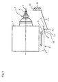
- a rotatably driven about a spindle axis 2 work spindle 3 is arranged, one axial end of a jig 4 for a workpiece, for example in the form of a gear blank or a toothed shaft blank having.
- the first carriage 1 is adjustable along a linear first movement axis between a first position and a second position. The adjusting movement along the first axis of movement parallel to the spindle axis 2 is indicated by a double arrow 5.
- Attached to the first carriage 1 is a schematically indicated cam track 6, which has a first track section 7 parallel to the first movement axis, an adjoining ramp-shaped track section 8 inclined to the first movement axis and an adjoining second track section 9 parallel to the first movement axis ,
- the second track section 9 has a smaller distance to the spindle axis 2 than the first track section 7.
- a schematically indicated second carriage 10 which serves to support a measuring sensor (not shown), is adjustable along a linear second movement axis orthogonal to the first movement axis between a measuring position and a rest position withdrawn from the measuring position.
- the adjustment movement of the second carriage 10 along the second movement axis is indicated by a double arrow 11.
- a lever arrangement which can be pivoted about a pivot axis 12 which is orthogonal to the first and the second movement axis, has a first lever arm 13 and a second lever arm 14.
- the first lever arm 13 extends from the relative to the first carriage 1 and the second carriage 10 stationary pivot axis 12 in the direction of the cam track 6 and is provided at its cam track 6 facing end with a rotatably mounted roller 15, whose axis of rotation parallel to the pivot axis 12 extends.
- the roller 15 is held by a suitable means, for example, a lever assembly with respect to the pivot axis 12 in the clockwise direction with a torsional force stressing spring (not shown), on the cam track 6 in abutment.
- the second lever arm 14 extends from the pivot axis 12 to the second carriage 10 and is hinged thereto so that it follows a pivoting of the second lever arm 14 by a longitudinal direction of the double arrow 11 directed adjusting movement.
- Fig. 1 is the first carriage 1 in its first position, wherein on the jig 4 a machined gear blank (not shown) is clamped.
- the indexing sensor constituting the sensor (not shown) supported on the second carriage 10 is in its measuring position approximating the workpiece, in which the indexing operation is carried out.
- the first carriage 1 is moved by its movement drive (not shown) along the first axis of movement in the direction of the in relation to Fig. 1 shown first position further right second position adjusted.
- the previously applied to the second path section 9 of the cam track 6 roller 15 runs on the in Fig. 1 to the right moving ramp-shaped track section 8.
- first lever arm 13 is pivoted about the pivot axis 12 in the clockwise direction and the second carriage 10 is retracted by the ratio of the lever assembly corresponding adjustment movement of the second lever arm 14 relative to the spindle axis 2 until it passes through the roller 15 through the ramp-shaped path section 8 by the system of the roller 15 has reached certain resting position on the adjoining first path section 7.
- the second carriage 10 with the probe so far away from the spindle axis 2 that a collision is excluded with it as a result of the adjustment movement 5 of the first carriage 1 to the right moving parts.
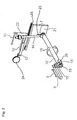
- FIG. 2 illustrated second embodiment also has the in Fig. 1 on the basis of the reference numerals 1 to 11 explained embodiment. However, in Fig. 2 only the adjusting movement 5 of the first carriage 1 following curved path 6 shown.
- the illustration of the second carriage 10 is in Fig. 2 across from Fig. 1 through the presentation its stationary guideway 16, through which it is performed according to its adjusting movement 11 along the second axis of movement, supplemented.
- the holder 17 of the probe on the second carriage 10 and the workpiece 24 indicated.
- the difference from in Fig. 1 illustrated embodiment consists essentially in that the pivot axis 12 'is arranged parallel to the first axis of movement.
- the pivoting movement taking place about the pivot axis 12 'is illustrated by a double arrow 18.
- the pivotal axis 12 'forming rod-shaped part is rotatably mounted at its to the cam track 6 facing axial end 19 in a stationary bearing 20 and at its opposite axial end in a guide track 16 supporting stationary bearing plate 21.
- the first lever arm 13 'extending radially with respect to the pivot axis 12' is arranged, at the free end of which the roller 15 'engaging with the cam track 6 is rotatably mounted.
- the second lever arm 14 ' extends from the axial end 19 opposite axial end of the pivot axis 12' forming rod-shaped part from radially to a mounted on the second carriage 10 part 22, in which an orthogonal to the second axis of movement guide slot is formed.
- This guide slot a fixed to the second lever arm 14 'guide pin is guided.
- the guide slot accommodates the movement component of the pivoting movement of the second lever arm 14 'that is orthogonal to the second movement path, while the component of this pivoting movement parallel to the second movement axis causes a corresponding adjustment movement of the second carriage 10.
- Fig. 1 is also the about the pivot axis 12 'centered torsion spring 23 recognizable, one end of which is supported on the second lever arm 14' and the other end to the stationary bearing plate 21 so that it exerts a torque by which the roller 15 'on the curved path 6 is held in investment.
Landscapes
- Engineering & Computer Science (AREA)
- Mechanical Engineering (AREA)
- Machine Tool Units (AREA)
- A Measuring Device Byusing Mechanical Method (AREA)
- Turning (AREA)
- Transmission Devices (AREA)
Abstract
Die Erfindung betrifft eine Schlittenanordnung für eine Werkzeugmaschine mit einem längs einer ersten Bewegungsachse verstellbaren ersten Schlitten (1), durch dessen Verstellbewegung (5) ein auf dem ersten Schlitten (1) abgestütztes Werkstück zwischen einer ersten Position und einer zweiten Position verstellbar ist und mit einem längs einer zweiten Bewegungsachse verstellbaren zweiten Schlitten (10), durch dessen Verstellbewegung (11) ein auf dem zweiten Schlitten (10) abgestützter Meßfühler zwischen einer an der ersten Position des Werkstücks angenäherten Meßposition und einer von der Meßposition abgerückten Ruheposition verstellbar ist, sodaß eine von der Verstellbewegung des ersten Schlittens angetriebene Betätigungsvorrichtung (6,13,14) vorgesehen ist, durch die infolge der Verstellbewegung (5) des ersten Schlittens (1) von der ersten Position in die zweite Position die Verstellbewegung (11) des zweiten Schlittens (10) von der Meßposition in die Ruheposition und infolge der Verstellbewegung (5) des ersten Schlittens (1) von der zweiten Position in die erste Position die Verstellbewegung (11) des zweiten Schlittens (10) von der Ruheposition in die Meßposition antreibbar ist.

Description
Die Erfindung bezieht sich auf eine Schlittenanordnung für eine Werkzeugmaschine mit einem längs einer ersten Bewegungsachse verstellbaren ersten Schlitten, durch dessen Verstellbewegung ein auf dem ersten Schlitten abgestütztes Werkstück zwischen einer ersten Position und einer zweiten Position verstellbar ist und mit einem längs einer zweiten Bewegungsachse verstellbaren zweiten Schlitten, durch dessen Verstellbewegung ein auf dem zweiten Schlitten abgestützter Meßfühler zwischen einer an die erste Position des Werkstücks angenäherten Meßposition und einer von der Meßposition abgerückten Ruheposition verstellbar ist.The invention relates to a carriage arrangement for a machine tool having a first carriage which can be adjusted along a first axis of movement, by the adjusting movement of which a workpiece supported on the first carriage is adjustable between a first position and a second position and with a second carriage which is adjustable along a second axis of movement , By the adjustment of which a sensor supported on the second carriage can be adjusted between a measuring position approximated to the first position of the workpiece and a rest position withdrawn from the measuring position.
Derartige Schlittenanordnungen finden insbesondere in Werkzeugmaschinen Anwendung, die zur Feinbearbeitung von Zahnradrohlingen dienen. Für diese Werkstücke ist eine Indexierung, d.h. eine Erfassung ihrer Drehposition durch den Meßfühler, erforderlich, damit eine für die Feinbearbeitung geeignete Relativstellung zwischen dem Werkstück und einem Bearbeitungswerkzeug, beispielsweise einem Honrad, eingestellt werden kann. Dabei ist üblicherweise der das Werkstück bildende Zahnradrohling auf einer drehend antreibbaren Arbeitsspindel aufgespannt, welche auf dem ersten Schlitten abgestützt ist.Such carriage arrangements are used in particular in machine tools, which are used for fine machining of gear blanks. For these workpieces an indexing, ie a detection of their rotational position by the probe required, so that suitable for fine machining relative position between the workpiece and a machining tool, such as a honing wheel, can be adjusted. In this case, usually forming the workpiece gear blank is clamped on a rotatably driven work spindle, which is supported on the first carriage.
Für diese Indexierung wird der das Werkstück abstützende erste Schlitten in seine erste Position gebracht und der den Indexiersensor bildende Meßfühler sehr dicht an das Werkstück herangeführt, indem der den Meßfühler tragende zweite Schlitten in seine Meßposition verstellt wird. Nach der Indexierung muß der zweite Schlitten in seine von der Meßposition abgerückte Ruheposition zurückgezogen werden, damit das Werkstück auf dem ersten Schlitten für seine Feinbearbeitung in die zweite Position überführt werden kann, ohne daß es bei dieser Verstellbewegung zu einer Kollision zwischen dem Meßfühler und dem Werkstück, der das Werkstück aufspannenden Spannvorrichtung oder dem das Werkstück tragenden ersten Schlitten kommt. Dies schließt insbesondere auch den Fall ein, daß der erste Schlitten zunächst in eine Bestückungsposition verstellt wird, in der das Werkstück aufgespannt wird, und erst anschließend in seine erste Position verstellt wird. Dabei kann vorgesehen sein, daß der den Meßfühler tragende zweite Schlitten währenddessen in seiner Ruheposition verbleibt, um eine etwaige Kollision, beispielsweise mit einer Störkontur des aufgespannten Werkstücks, zu vermeiden, und erst danach in seine Meßposition nahe dem in der ersten Position angelangten Werkstück verstellt wird.For this indexing, the first carriage supporting the workpiece is brought into its first position and the sensor forming the indexing sensor is brought very close to the workpiece by adjusting the second carriage supporting the sensor to its measuring position. After indexing, the second carriage must be retracted to its rest position withdrawn from the measuring position so that the workpiece on the first carriage can be transferred to its second position for fine machining without collision between the sensor and the workpiece during this adjustment movement which comes the workpiece clamping jig or the workpiece carrying the first carriage. This includes in particular the case that the first carriage is initially adjusted to a loading position in which the workpiece is clamped, and only then adjusted to its first position. It can be provided that the sensor carrying the second carriage meanwhile remains in its rest position to avoid any collision, for example, with a disturbing contour of the clamped workpiece, and only then adjusted in its measuring position near the workpiece reached in the first position ,
Herkömmlich werden diese Verstellbewegungen durch einen elektrischen, pneumatischen oder hydraulischen Antrieb realisiert. Um sicherzustellen, daß sich dabei der Meßfühler nicht im Kollisionsbereich befindet, wird die Momentanposition des den Meßfühler tragenden zweiten Schlittens von Positionssensoren abgefragt. Die Verstellbewegung des das Werkstück tragenden ersten Schlittens von seiner ersten Stellung, in der die Indexierung durchgeführt worden ist, und seiner zweiten Stellung, von der aus das Werkstück mit dem Bearbeitungswerkzeug in Eingriff gebracht wird, wird erst dann gestartet, wenn die den zweiten Schlitten überwachenden Positionssensoren ein Freigabesignal abgeben. Somit erfolgen das Zurückziehen des Meßfühlers aus seiner Meßposition und das Vorfahren des Werkstücks in seine zweite Position zeitlich nacheinander. Dies bedingt bei einem seriellen Ablauf des Zurückziehens des zweiten Schlittens und des Vorfahrens des ersten Schlittens eine Nebenzeit, die der Summe der für die Verstellbewegung des zweiten Schlittens zwischen der Meßposition und der Ruheposition und der Verstellbewegung des ersten Schlittens zwischen der ersten und der zweiten Position erforderlichen Zeiten entspricht.Conventionally, these adjustment movements are realized by an electric, pneumatic or hydraulic drive. To ensure that the sensor is not in the collision area, the instantaneous position of the second carriage supporting the sensor is interrogated by position sensors. The adjustment movement of the workpiece carrying the first carriage from its first position in which the indexing has been performed, and its second position, from which the workpiece is brought into engagement with the machining tool, is only started when the second carriage monitoring Position sensors release an enable signal. Thus, the retraction of the probe from its measuring position and the ancestor of the workpiece in its second position take place in succession. This causes in a serial process of retraction of the second carriage and the ancestor of the first carriage an idle time, the sum of the required for the adjustment movement of the second carriage between the measuring position and the rest position and the adjustment movement of the first carriage between the first and the second position Times corresponds.
Der Erfindung liegt die Aufgabe zugrunde, eine Schlittenanordnung der eingangs genannten Art derart auszubilden, daß diese Nebenzeiten verkürzt werden.The invention has the object of providing a slide assembly of the type mentioned in such a way that these non-productive times are shortened.
Erfindungsgemäß wird diese Aufgabe dadurch gelöst, daß eine von der Verstellbewegung des ersten Schlittens angetriebene Betätigungsvorrichtung vorgesehen ist, durch die infolge der Verstellbewegung des ersten Schlittens von der ersten Position in die zweite Position die Verstellbewegung des zweiten Schlittens von der Meßposition in die Ruheposition und infolge der Verstellbewegung des ersten Schlittens von der zweiten Position in die erste Position die Verstellbewegung des zweiten Schlittens von der Ruheposition in die Meßposition antreibbar ist.According to the invention, this object is achieved in that a driven by the adjustment of the first carriage actuator is provided by the adjusting movement of the second carriage from the first position to the second position due to the adjusting movement of the second carriage from the measuring position to the rest position and due Adjusting movement of the first carriage from the second position to the first position, the adjusting movement of the second carriage from the rest position to the measuring position can be driven.
Durch die erfindungsgemäße Lösung werden der Vorgang der Verstellung des Meßfühlers zwischen seiner Meßposition und seiner Ruheposition und der Vorgang der Verstellung des Werkstücks zwischen seiner ersten und seiner zweiten Position parallelisiert. Die erfindungsgemäß vorgesehene Betätigungsvorrichtung bewirkt eine mechanisch zwangsgeführte Kopplung der Verstellbewegungen der beiden Schlitten. Dadurch wird die Rückzugsbewegung des den Meßfühler abstützenden zweiten Schlittens von der Vorschubbewegung des das Werkstück tragenden ersten Schlittens derart zwangsgesteuert, daß mit der Vorschubbewegung des ersten Schlittens der zweite Schlitten zwangsläufig aus dem Kollisionsbereich zurückgezogen wird.By the solution according to the invention the process of adjustment of the probe between its measuring position and its rest position and the process of adjustment of the workpiece between its first and its second position are parallelized. The inventively provided actuator causes a mechanically positively guided coupling of the adjustment movements of the two carriages. Characterized the retraction movement of the sensor supporting the second carriage is forcibly controlled by the advancing movement of the workpiece carrying the first carriage such that with the advancing movement of the first carriage, the second carriage is forcibly withdrawn from the collision area.
Die Erfindung ist insbesondere für den Fall anwendbar, daß die erste Bewegungsachse und die zweite Bewegungsachse linear und zueinander orthogonal sind. Dabei wird die lineare Verstellbewegung des ersten Schlittens durch die Betätigungsvorrichtung in eine dazu orthogonale, seitliche Verstellbewegung des zweiten Schlittens umgesetzt. Beispielsweise ist das Werkstück auf eine auf dem ersten Schlitten abgestützte, drehend antreibbare Arbeitsspindel aufgespannt, deren Spindelachse sich parallel zur ersten Bewegungsachse erstreckt. Der den Meßfühler tragende zweite Schlitten weicht dann bei einer Vorschubbewegung des Werkstücks orthogonal zur Spindelachse seitlich aus.The invention is particularly applicable to the case that the first movement axis and the second movement axis are linear and mutually orthogonal. In this case, the linear adjustment movement of the first carriage is converted by the actuating device into an orthogonal, lateral adjustment movement of the second carriage. For example, the workpiece is mounted on a supported on the first slide, rotatably driven work spindle whose spindle axis extends parallel to the first axis of movement. The sensor carrying the second carriage then deviates laterally at a feed movement of the workpiece orthogonal to the spindle axis.
In einer zweckmäßigen Ausführungsform ist vorgesehen, daß die Betätigungsvorrichtung eine an dem ersten Schlitten festgelegte Kurvenbahn und eine einen ersten Hebelarm, einen zweiten Hebelarm und eine gegenüber den beiden Schlitten stationäre Schwenkachse aufweisende Hebelanordnung aufweist, deren erster Hebelarm infolge der Verstellbewegung des ersten Schlittens von der Kurvenbahn verschwenkt wird und deren zweiter Hebelarm dadurch die Verstellbewegung des zweiten Schlittens antreibt. Durch die sich entsprechend der Verstellbewegung des ersten Schlittens in Bezug auf die stationäre Schwenkachse der Hebelanordnung verändernde Lage der Kurvenbahn erfährt der erste Hebelarm eine entsprechende Verschwenkung, die durch den zweiten Hebelarm in eine entsprechende Antriebsbewegung für den zweiten Schlitten umgesetzt wird. Wenn die erste Bewegungsachse linear ist, kann beispielsweise die Kurvenbahn zwei zur ersten Bewegungsachse parallele, jedoch in unterschiedlichen Abständen von dieser angeordnete Bahnabschnitte aufweisen, die durch einen rampenförmigen Bahnabschnitt miteinander verbunden sind. In diesem Fall bestimmen die beiden zur ersten Bewegungsachse parallelen Bahnabschnitte die beiden Endpositionen der Verschwenkung des ersten Hebelarms, während die Einwirkung des rampenförmigen Bahnabschnitts die Verschwenkung zwischen diesen beiden Endpositionen bewirkt.In an expedient embodiment it is provided that the actuating device has a cam track fixed to the first carriage and a lever arrangement having a first lever arm, a second lever arm and a pivot axis stationary with respect to the two carriages, the first lever arm as a result of the adjusting movement of the first carriage from the curved path is pivoted and their second lever arm thereby drives the adjustment movement of the second carriage. As a result of the position of the curved path changing in accordance with the adjustment movement of the first slide relative to the stationary pivot axis of the lever arrangement, the first lever arm experiences a corresponding pivoting, which is converted by the second lever arm into a corresponding drive movement for the second slide. If the first movement axis is linear, for example, the curved path may have two track sections which are parallel to the first movement axis but at different distances therefrom and which are interconnected by a ramp-shaped track section. In this case, the two track sections parallel to the first movement axis determine the two end positions of the pivoting of the first lever arm, while the action of the ramped track section causes the pivoting between these two end positions.
Die Vermittlung der Einwirkung der Kurvenbahn auf den ersten Hebelarm erfolgt vorteilhaft dadurch, daß der erste Hebelarm eine daran drehbar gelagerte und sich auf der Kurvenbahn abwälzende Rolle aufweist. Dabei kann die Kurvenbahn beispielsweise derart ausgebildet sein, daß sie die Rolle zwischen zwei zueinander gleichförmigen Steuerkurven zwangsführt. Dagegen besteht eine besonders einfache Alternative darin, daß die Rolle durch eine ein um die Schwenkachse wirkendes Torsionsmoment erzeugende Feder mit der Kurvenbahn in Eingriff gehalten wird. Ferner kann es für die Führungsfunktion der Kurvenbahn vorteilhaft sein, statt nur einer Rolle mehrere Rollen vorzusehen.The mediation of the action of the cam track on the first lever arm is advantageously carried out in that the first lever arm has a rotatably mounted thereon and rolling on the curved path roller. In this case, the cam track may for example be designed such that it forcibly leads the roller between two mutually uniform control cams. On the other hand, a particularly simple alternative is that the roller is held in engagement with the cam track by a spring which generates a torsional moment acting about the pivot axis. Furthermore, it may be advantageous for the guiding function of the cam track to provide a plurality of rollers instead of just one roller.
Die räumliche Ausrichtung der Schwenkachse der Hebelanordnung kann je nach den baulichen Erfordernissen der Werkzeugmaschine weitgehend frei gewählt werden und unterliegt lediglich der Einschränkung, daß aus der Schwenkbewegung des zweiten Hebelarms eine längs der zweiten Bewegungsachse wirksame Bewegungskomponente ableitbar sein muß. Eine in diesem Rahmen zweckmäßige Ausführungsform besteht darin, daß die Schwenkachse orthogonal zur ersten und zweiten Bewegungsachse angeordnet ist. Andererseits kann in einer zweckmäßigen Alternative vorgesehen sein, daß die Schwenkachse parallel zur ersten Bewegungsachse angeordnet ist.The spatial orientation of the pivot axis of the lever assembly can be largely freely selected depending on the structural requirements of the machine tool and is subject only to the restriction that from the pivotal movement of the second lever arm along the second axis of motion effective movement component must be derivable. A useful embodiment in this context is that the pivot axis is arranged orthogonal to the first and second axes of movement. On the other hand, it can be provided in an expedient alternative that the pivot axis is arranged parallel to the first axis of movement.
Ebenso besteht hinsichtlich der Ebenen, in denen die Verschwenkbewegung der beiden Hebelarme stattfindet, eine weitgehende Wahlfreiheit, die eine Anpassung an die jeweiligen baulichen Gegebenheiten der Werkzeugmaschine ermöglicht. Insbesondere zeichnet sich eine zweckmäßige Ausführungsform dadurch aus, daß der erste und der zweite Hebelarm in der Richtung der Schwenkachse voneinander beabstandet sind.Likewise, with regard to the planes in which the pivoting movement of the two lever arms takes place, there is a large degree of freedom of choice, which allows adaptation to the respective constructional conditions of the machine tool. Especially a useful embodiment is characterized in that the first and the second lever arm are spaced apart in the direction of the pivot axis.
In der folgenden Beschreibung wird die Erfindung anhand von zwei Ausführungsformen unter Bezugnahme auf die Zeichnung beispielhaft erläutert. Es zeigen:
- Fig. 1
- eine schematische Darstellung einer ersten Ausführungsform, und
- Fig. 2
- eine etwas detailliertere Teildarstellung einer zweiten Ausführungsform.
- Fig. 1
- a schematic representation of a first embodiment, and
- Fig. 2
- a more detailed partial representation of a second embodiment.
Bei einer in
An dem ersten Schlitten 1 ist eine schematisch angedeutete Kurvenbahn 6 befestigt, die einen zu der ersten Bewegungsachse parallelen ersten Bahnabschnitt 7, einen daran anschließenden, zu der ersten Bewegungsachse geneigten rampenförmigen Bahnabschnitt 8 und einen daran anschließenden, zu der ersten Bewegungsachse parallelen zweiten Bahnabschnitt 9 aufweist. Der zweite Bahnabschnitt 9 weist einen geringeren Abstand zu der Spindelachse 2 auf als der erste Bahnabschnitt 7.Attached to the
Ein schematisch angedeuteter zweiter Schlitten 10, der zur Abstützung eines Meßfühlers (nicht dargestellt) dient, ist längs einer zu der ersten Bewegungsachse orthogonalen, linearen zweiten Bewegungsachse zwischen einer Meßposition und einer von der Meßposition abgerückten Ruheposition verstellbar. Die Verstellbewegung des zweiten Schlittens 10 längs der zweiten Bewegungsachse ist durch einen Doppelpfeil 11 angedeutet.A schematically indicated
Eine um eine zu der ersten und der zweiten Bewegungsachse orthogonale Schwenkachse 12 verschwenkbare Hebelanordnung weist einen ersten Hebelarm 13 und einen zweiten Hebelarm 14 auf. Der erste Hebelarm 13 erstreckt sich von der in Bezug auf den ersten Schlitten 1 und den zweiten Schlitten 10 stationären Schwenkachse 12 in Richtung auf die Kurvenbahn 6 und ist an seinem zur Kurvenbahn 6 weisenden Ende mit einer daran drehbar gelagerten Rolle 15 versehen, deren Drehachse parallel zur Schwenkachse 12 verläuft. Die Rolle 15 wird durch ein geeignetes Mittel, beispielsweise eine die Hebelanordnung in Bezug auf die Schwenkachse 12 im Uhrzeigersinn mit einer Torsionskraft belastende Feder (nicht dargestellt), an der Kurvenbahn 6 in Anlage gehalten.A lever arrangement, which can be pivoted about a
Der zweite Hebelarm 14 erstreckt sich von der Schwenkachse 12 zu dem zweiten Schlitten 10 und ist an diesem derart angelenkt, daß er einer Verschwenkung des zweiten Hebelarms 14 durch eine längs des Doppelpfeils 11 gerichtete Verstellbewegung folgt.The
In
Eine in
Der Unterschied gegenüber der in
Der zweite Hebelarm 14' erstreckt sich von dem dem axialen Ende 19 entgegengesetzten axialen Ende des die Schwenkachse 12' bildenden stabförmigen Teils aus radial bis zu einem an dem zweiten Schlitten 10 befestigten Teil 22, in dem ein zur zweiten Bewegungsachse orthogonaler Führungsschlitz ausgebildet ist. In diesem Führungsschlitz wird ein an dem zweiten Hebelarm 14' festgelegter Führungsbolzen geführt. Der Führungsschlitz nimmt die zur zweiten Bewegungsbahn orthogonale Bewegungskomponente der Schwenkbewegung des zweiten Hebelarms 14' auf, während die zur zweiten Bewegungsachse parallele Komponente dieser Schwenkbewegung eine entsprechende Verstellbewegung des zweiten Schlittens 10 hervorruft. In funktioneller Hinsicht wird also mit der in
In
- 11
- erster Schlittenfirst sled
- 22
- Spindelachsespindle axis
- 33
- Arbeitsspindelwork spindle
- 44
- Aufspannvorrichtungjig
- 55
- Doppelpfeil / VerstellbewegungDouble arrow / adjustment movement
- 66
- Kurvenbahncam track
- 77
- erster Bahnabschnittfirst track section
- 88th
- rampenförmiger Bahnabschnittramp-shaped track section
- 99
- zweiter Bahnabschnittsecond track section
- 1010
- zweiter Schlittensecond sled
- 1111
- Doppelpfeil / VerstellbewegungDouble arrow / adjustment movement
- 12, 12'12, 12 '
- Schwenkachseswivel axis
- 13, 13'13, 13 '
- erster Hebelarmfirst lever arm
- 14, 14'14, 14 '
- zweiter Hebelarmsecond lever arm
- 15, 15'15, 15 '
- Rollerole
- 1616
- Führungsbahnguideway
- 1717
- Halterungbracket
- 1818
- Doppelpfeil / SchwenkbewegungDouble arrow / swivel movement
- 1919
- axiales Endeaxial end
- 2020
- stationäres Lagerstationary warehouse
- 2121
- stationäre Lagerplattestationary bearing plate
- 2222
- Teilpart
- 2323
- Torsionsfedertorsion spring
- 2424
- Werkstückworkpiece
Claims (10)
Applications Claiming Priority (1)
| Application Number | Priority Date | Filing Date | Title |
|---|---|---|---|
| DE202007012868U DE202007012868U1 (en) | 2007-09-14 | 2007-09-14 | Slide arrangement for a machine tool |
Publications (2)
| Publication Number | Publication Date |
|---|---|
| EP2036645A2 true EP2036645A2 (en) | 2009-03-18 |
| EP2036645A3 EP2036645A3 (en) | 2012-05-02 |
Family
ID=38806448
Family Applications (1)
| Application Number | Title | Priority Date | Filing Date |
|---|---|---|---|
| EP08016008A Withdrawn EP2036645A3 (en) | 2007-09-14 | 2008-09-11 | Carriage for a machine tool |
Country Status (5)
| Country | Link |
|---|---|
| US (1) | US7712227B2 (en) |
| EP (1) | EP2036645A3 (en) |
| JP (1) | JP2009066752A (en) |
| CN (1) | CN101386134B (en) |
| DE (1) | DE202007012868U1 (en) |
Families Citing this family (8)
| Publication number | Priority date | Publication date | Assignee | Title |
|---|---|---|---|---|
| US20090174162A1 (en) * | 2007-12-21 | 2009-07-09 | Gass Stephen F | Mobile base for a table saw |
| US8246059B2 (en) * | 2008-02-29 | 2012-08-21 | Sd3, Llc | Mobile base for a table saw |
| JP5706430B2 (en) * | 2009-10-01 | 2015-04-22 | ザ グリーソン ワークス | Machine tool probe mechanism |
| TWI399502B (en) * | 2010-10-07 | 2013-06-21 | Rexon Ind Corp Ltd | Machine base assembly for machine tool |
| KR101401264B1 (en) * | 2012-06-27 | 2014-06-02 | 한국생산기술연구원 | Probe Mounting Jig of Separation and Combination |
| CN106054807B (en) * | 2016-06-24 | 2017-11-10 | 广汉快速铁路设备有限公司 | Non-pulling wheel lathe wheel is to anti-skidding monitoring system and its monitoring method |
| CN107097102B (en) * | 2017-05-03 | 2023-08-01 | 佛山职业技术学院 | Sensor clamp |
| CN110281037B (en) * | 2019-06-28 | 2021-09-03 | 航天神舟飞行器有限公司 | Measurement processing execution head suitable for aircraft skin hole making |
Family Cites Families (16)
| Publication number | Priority date | Publication date | Assignee | Title |
|---|---|---|---|---|
| JPS5721224A (en) * | 1980-07-16 | 1982-02-03 | Toyota Motor Corp | Indexing and positioning device of geat tooth chamfering machine |
| DE3638141A1 (en) * | 1986-11-08 | 1988-05-11 | Cima | Hobbing machine with checking device for the teeth of the part being machined |
| CH672182A5 (en) * | 1987-06-29 | 1989-10-31 | Meseltron Sa | |
| DE3934056A1 (en) * | 1989-10-12 | 1991-05-08 | Zeiss Carl Fa | PROBE HEAD FOR COORDINATE MEASURING DEVICES |
| US5297055A (en) * | 1990-04-20 | 1994-03-22 | The Gleason Works | Multi-functional measurement system |
| DE4204632A1 (en) * | 1990-08-28 | 1993-08-19 | Leitz Messtechnik | Centring unit for mechanical scanning head with follower and scanner - has two resetting elements reacting to follower in contrasting manner and one only multipart stop is provided for one reset element. |
| US5273717A (en) * | 1992-09-30 | 1993-12-28 | Eastman Kodak Company | Self-calibrating analyzer aspirator |
| IT1263452B (en) * | 1993-07-01 | 1996-08-05 | Marposs Spa | BUFFER COMPARATOR. |
| JP3874872B2 (en) * | 1996-05-27 | 2007-01-31 | ヤマザキマザック株式会社 | Spindle head 3-axis moving CNC lathe |
| DE19809690A1 (en) * | 1998-03-06 | 1999-09-09 | Zeiss Carl Fa | Coordinate measuring device with user guidance |
| GB0201845D0 (en) * | 2002-01-26 | 2002-03-13 | Renishaw Plc | Analogue probe |
| GB0215152D0 (en) * | 2002-07-01 | 2002-08-07 | Renishaw Plc | Probe or stylus orientation |
| DE20218352U1 (en) * | 2002-11-26 | 2003-01-23 | Reishauer Ag, Wallisellen | Centering device for aligning pre-toothed workpieces on gear finishing machines |
| ATE340987T1 (en) * | 2003-01-29 | 2006-10-15 | Tesa Sa | STYLE WITH ADJUSTABLE ORIENTATION |
| GB2417090A (en) * | 2003-04-28 | 2006-02-15 | Stephen James Crampton | CMM arm with exoskeleton |
| JP4759104B2 (en) * | 2005-08-26 | 2011-08-31 | 株式会社ユネクス | Sensor holding device |
-
2007
- 2007-09-14 DE DE202007012868U patent/DE202007012868U1/en not_active Expired - Lifetime
-
2008
- 2008-09-08 US US12/231,927 patent/US7712227B2/en not_active Expired - Fee Related
- 2008-09-11 EP EP08016008A patent/EP2036645A3/en not_active Withdrawn
- 2008-09-12 CN CN2008101609011A patent/CN101386134B/en not_active Expired - Fee Related
- 2008-09-12 JP JP2008234135A patent/JP2009066752A/en active Pending
Also Published As
| Publication number | Publication date |
|---|---|
| CN101386134B (en) | 2012-01-11 |
| CN101386134A (en) | 2009-03-18 |
| US20090072117A1 (en) | 2009-03-19 |
| DE202007012868U1 (en) | 2007-12-06 |
| US7712227B2 (en) | 2010-05-11 |
| EP2036645A3 (en) | 2012-05-02 |
| JP2009066752A (en) | 2009-04-02 |
Similar Documents
| Publication | Publication Date | Title |
|---|---|---|
| EP2036645A2 (en) | Carriage for a machine tool | |
| DE3322944C2 (en) | Die ejector device for multi-stage forming machines | |
| DE69708834T2 (en) | Mold die made of thin sheet metal | |
| DE2353833C3 (en) | Control device for the grinding slide of a grinding machine | |
| DE3017613C2 (en) | ||
| DE1233696B (en) | Device for the automatic supply and removal of workpieces on machine tools, in particular pistons on a lathe | |
| DE19722308C1 (en) | Static cylinder machine for crankshafts | |
| EP1884303B1 (en) | Method for centring workpieces and device for performing such a method | |
| DE3016047A1 (en) | SWITCHABLE BENDING MACHINE | |
| DE2530813A1 (en) | MACHINING DEVICE FOR PISTON | |
| DE4419656C2 (en) | Device for measuring diameter and / or roundness in eccentric cylindrical grinding | |
| EP2218545B1 (en) | Device and method for fine processing of a rotation-symmetric workpiece surface | |
| DE1800871B2 (en) | Honing or grinding device for simultaneous machining of a workpiece with a central bore, two end faces and a characteristic circle (e.g. pitch circle or outer surface), such as a gear wheel or a bearing race | |
| EP1428612B1 (en) | Device and method for the angular positioning of eccentric workpieces such as crankshafts, by means of indexing jaws on a steady rest | |
| DE2245994A1 (en) | MULTI-SPINDLE LATHE | |
| DE69416919T2 (en) | Cutting machine for the automatic cutting and turning of pipes | |
| DE69309593T2 (en) | Leaf spring tensioner | |
| DE69000735T2 (en) | MECHANISM WITH LOW INERTIA FOR REINSTALLING A WORKPIECE IN A PILGRIMING ROLLER. | |
| DE102022108639B3 (en) | Stop device for a lathe | |
| DE1502492B1 (en) | Copy grinder | |
| DE10063154A1 (en) | Forging press with adjusting device on the die side | |
| EP1413369A1 (en) | Device and method for bending bar-shaped elements | |
| DE1577371C3 (en) | Grinding machine for producing a number of circumferential projections on a cylindrical workpiece | |
| DE19613169C2 (en) | Device for machine straightening of rotationally symmetrical workpieces | |
| DD268589A3 (en) | GRIPPER WITH FLOATING GRIPPER HEAD FOR INDUSTRIAL ROBOT |
Legal Events
| Date | Code | Title | Description |
|---|---|---|---|
| PUAI | Public reference made under article 153(3) epc to a published international application that has entered the european phase |
Free format text: ORIGINAL CODE: 0009012 |
|
| AK | Designated contracting states |
Kind code of ref document: A2 Designated state(s): AT BE BG CH CY CZ DE DK EE ES FI FR GB GR HR HU IE IS IT LI LT LU LV MC MT NL NO PL PT RO SE SI SK TR |
|
| AX | Request for extension of the european patent |
Extension state: AL BA MK RS |
|
| PUAL | Search report despatched |
Free format text: ORIGINAL CODE: 0009013 |
|
| AK | Designated contracting states |
Kind code of ref document: A3 Designated state(s): AT BE BG CH CY CZ DE DK EE ES FI FR GB GR HR HU IE IS IT LI LT LU LV MC MT NL NO PL PT RO SE SI SK TR |
|
| AX | Request for extension of the european patent |
Extension state: AL BA MK RS |
|
| RIC1 | Information provided on ipc code assigned before grant |
Ipc: B23F 19/05 20060101ALI20120326BHEP Ipc: B23F 23/12 20060101ALI20120326BHEP Ipc: B23F 23/08 20060101AFI20120326BHEP |
|
| AKY | No designation fees paid | ||
| REG | Reference to a national code |
Ref country code: DE Ref legal event code: R108 |
|
| REG | Reference to a national code |
Ref country code: DE Ref legal event code: R108 Effective date: 20130109 |
|
| STAA | Information on the status of an ep patent application or granted ep patent |
Free format text: STATUS: THE APPLICATION IS DEEMED TO BE WITHDRAWN |
|
| 18D | Application deemed to be withdrawn |
Effective date: 20121103 |