EP2035905B1 - Kryo-detektorvorrichtung mit temperaturstabilisierungseinrichtung - Google Patents
Kryo-detektorvorrichtung mit temperaturstabilisierungseinrichtung Download PDFInfo
- Publication number
- EP2035905B1 EP2035905B1 EP07786930A EP07786930A EP2035905B1 EP 2035905 B1 EP2035905 B1 EP 2035905B1 EP 07786930 A EP07786930 A EP 07786930A EP 07786930 A EP07786930 A EP 07786930A EP 2035905 B1 EP2035905 B1 EP 2035905B1
- Authority
- EP
- European Patent Office
- Prior art keywords
- stage
- temperature
- cold head
- magnetic field
- cooling
- Prior art date
- Legal status (The legal status is an assumption and is not a legal conclusion. Google has not performed a legal analysis and makes no representation as to the accuracy of the status listed.)
- Active
Links
Images


Classifications
-
- F—MECHANICAL ENGINEERING; LIGHTING; HEATING; WEAPONS; BLASTING
- F25—REFRIGERATION OR COOLING; COMBINED HEATING AND REFRIGERATION SYSTEMS; HEAT PUMP SYSTEMS; MANUFACTURE OR STORAGE OF ICE; LIQUEFACTION SOLIDIFICATION OF GASES
- F25B—REFRIGERATION MACHINES, PLANTS OR SYSTEMS; COMBINED HEATING AND REFRIGERATION SYSTEMS; HEAT PUMP SYSTEMS
- F25B25/00—Machines, plants or systems, using a combination of modes of operation covered by two or more of the groups F25B1/00 - F25B23/00
-
- F—MECHANICAL ENGINEERING; LIGHTING; HEATING; WEAPONS; BLASTING
- F25—REFRIGERATION OR COOLING; COMBINED HEATING AND REFRIGERATION SYSTEMS; HEAT PUMP SYSTEMS; MANUFACTURE OR STORAGE OF ICE; LIQUEFACTION SOLIDIFICATION OF GASES
- F25B—REFRIGERATION MACHINES, PLANTS OR SYSTEMS; COMBINED HEATING AND REFRIGERATION SYSTEMS; HEAT PUMP SYSTEMS
- F25B21/00—Machines, plants or systems, using electric or magnetic effects
-
- F—MECHANICAL ENGINEERING; LIGHTING; HEATING; WEAPONS; BLASTING
- F25—REFRIGERATION OR COOLING; COMBINED HEATING AND REFRIGERATION SYSTEMS; HEAT PUMP SYSTEMS; MANUFACTURE OR STORAGE OF ICE; LIQUEFACTION SOLIDIFICATION OF GASES
- F25B—REFRIGERATION MACHINES, PLANTS OR SYSTEMS; COMBINED HEATING AND REFRIGERATION SYSTEMS; HEAT PUMP SYSTEMS
- F25B2321/00—Details of machines, plants or systems, using electric or magnetic effects
- F25B2321/002—Details of machines, plants or systems, using electric or magnetic effects by using magneto-caloric effects
- F25B2321/0021—Details of machines, plants or systems, using electric or magnetic effects by using magneto-caloric effects with a static fixed magnet
-
- Y—GENERAL TAGGING OF NEW TECHNOLOGICAL DEVELOPMENTS; GENERAL TAGGING OF CROSS-SECTIONAL TECHNOLOGIES SPANNING OVER SEVERAL SECTIONS OF THE IPC; TECHNICAL SUBJECTS COVERED BY FORMER USPC CROSS-REFERENCE ART COLLECTIONS [XRACs] AND DIGESTS
- Y02—TECHNOLOGIES OR APPLICATIONS FOR MITIGATION OR ADAPTATION AGAINST CLIMATE CHANGE
- Y02B—CLIMATE CHANGE MITIGATION TECHNOLOGIES RELATED TO BUILDINGS, e.g. HOUSING, HOUSE APPLIANCES OR RELATED END-USER APPLICATIONS
- Y02B30/00—Energy efficient heating, ventilation or air conditioning [HVAC]
Definitions
- the invention relates to a cryogenic detector device according to the preamble of claim 1.
- a cryogenic detector device in which a sensor device with a mechanical cooling device is cooled to the desired cooling temperature T minK .
- T minK desired cooling temperature
- ⁇ ⁇ T 1 temperature fluctuations at the cold head of the cooling device.
- T s T mink ⁇ ⁇ T 2 with ⁇ T 2 ⁇ T 1 .
- they can also dampen the disturbing temperature fluctuations ⁇ ⁇ T 1 by virtue of the cold head of the mechanical cooling device being thermally coupled directly to a large heat capacity. If the heat capacity is weakly coupled to the cold head, the temperature fluctuations ⁇ ⁇ T 1 can be further reduced.
- the disadvantage here is that it takes a very long time until everything has cooled from room temperature to the desired temperature.
- a demagnetization stage By means of a demagnetization stage (EM stage), the temperature fluctuations occurring by the cooling device, in particular in the case of a mechanical cooling device, can be compensated.
- the EM stage is in this case thermally coupled to the sensor device and / or the cold head.
- a magnetic field by applying a magnetic field, the magnetic moments of a paramagnetic material, e.g. a paramagnetic salt, at least partially aligned.
- this magnetization heat is released, which is usually dissipated by a pre-cooling stage. If now the magnetic field is lowered, the orientation of the magnetic moments is canceled. The necessary energy is removed from the material, the material cools down.
- both the commonly used cooling effect of an EM stage and its "heating effect” can now be used when starting up the magnetic field.
- the EM stage acts as a "heater” and by lowering the magnetic field, the EM stage acts as a cooling device.
- this raising and lowering of the magnetic field in push-pull to the temperature fluctuations ⁇ .DELTA.T 1 performed the mechanical cooling device be compensated so that the temperature fluctuations in push-pull.
- the frequency of this temperature fluctuation ⁇ .DELTA.T 1 is here in a range of 1 to 100 Hz. Consequently, the magnetic field in the push-pull with this frequency has to be raised and lowered.
- the method also works for any disturbances of the equilibrium temperature with time constants up to ms.
- the EM stage and / or the sensor device is weakly coupled to the cooling device.
- This weak coupling dampens temperature fluctuations.
- the power requirements for the EM stage are reduced. This also reduces the size of magnet, salt pill, etc.
- the cooling device When coupled to the cooling device, a higher power is required, but the position of the sensor device is arbitrary, since all parts are kept in balance.
- the temperature stabilization comprises a heating element which is thermally coupled to the sensor device and / or the cold head and / or the EM stage. This heater sets the operating point of the EM stage. It is achieved that the EM stage is kept in its dynamic range, i. means that the required magnetic field is neither too high nor too low.
- the temperature stabilization is additionally improved - Claim 6.
- the heating element can be pulsed in push-pull to the temperature variation.
- the first embodiment according to Fig. 1 has a sensor device 2, which is connected via a first thermal coupling device 4 with a cold head 6, a mechanical cooling device, not shown.
- the sensor device 2 is connected to a demagnetization stage or EM stage 10 via a second thermal coupling device 8.
- the cold head 6 is cooled to a minimum cooling temperature T minK . Due to the characteristics of the mechanical cooling devices, the minimum cooling temperature T mink varies by a first temperature difference ⁇ ⁇ T 1 . ⁇ T 1 is in this case of the order of magnitude of 0.1 K. Due to the weak thermal coupling of the sensor device 2 to the cold head 6, this temperature fluctuation is transmitted to the sensor device 2 in a damped manner. In order to compensate for this temperature fluctuation ⁇ ⁇ T 1 , a temperature stabilizing device in the form of the EM stage 10 is provided.
- the EM stage 10 which is thermally connected via the second thermal coupling device 8 to the sensor device 2 in the push-pull to the temperature fluctuation ⁇ .DELTA.T 1 of the cold head 6 to ⁇ .DELTA.T K cooled or "heated", ie the magnetic field of the EM stage 10 is started - cooling - or lowered - heating. This raising or lowering of the magnetic field of the EM stage 10 takes place in push-pull with the same frequency at which the minimum cooling temperature T minK fluctuates.
- Fig. 2 shows a second embodiment of the invention, which differs from the first embodiment only in that the EM stage 10 is additionally connected via a third thermal coupling means 12 to the cold head 6.
- This additional coupling 12 between EM stage 10 and cold head 6 has the advantage that it is possible to set the dynamic range of the EM stage.
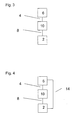
- Fig. 3 shows a third embodiment of the present invention, which differs from the first embodiment in that the Arrangement of EM stage 10 and sensor device 2 with respect to the cold head 6 have changed their place.
- This embodiment has the advantage that the EM stage can be designed structurally small and compact.
- Fig. 4 shows a variation of the third embodiment after Fig. 3 ,
- the cold head 6 is connected to the sensor device 2 via a fourth thermal coupling device 14.
- This embodiment can be advantageous if an EM stage 10 with high cooling capacity is used.
- Fig. 5 shows a fifth embodiment of the present invention in which the sensor device 2 and the EM stage 10 are independently thermally connected via a first and a second thermal coupling means 4 and 8 to the cold head 6.
- This embodiment can also be advantageous if an EM stage 10 with high cooling capacity is used.
- Fig. 6 shows a sixth embodiment of the invention, which differs from the first embodiment Fig. 1 differs in that is connected to the sensor device 2 via a fifth thermal coupling means 16, a heating element 18 to the sensor device 2.
- the heating element 18 on the one hand, the desired minimum cooling temperature T minK can be shifted upwards and, on the other hand, the temperature fluctuations ⁇ ⁇ T 1 can also be counteracted in a push-pull manner.
- the main effect of the heating element 18, however, is that it sets the operating point of the EM stage. This ensures that the EM stage does not leave its dynamic range.
Landscapes
- Engineering & Computer Science (AREA)
- Physics & Mathematics (AREA)
- Mechanical Engineering (AREA)
- Thermal Sciences (AREA)
- General Engineering & Computer Science (AREA)
- Measuring Magnetic Variables (AREA)
- Light Receiving Elements (AREA)
- Investigating Or Analysing Materials By Optical Means (AREA)
- Photometry And Measurement Of Optical Pulse Characteristics (AREA)
Description
- Die Erfindung betrifft eine Kryo-Detektorvorrichtung nach dem Oberbegriff des Anspruch 1.
- Aus der
DE 103 17 888.0 A ist eine Kryo-Detektorvorrichtung bekannt, bei der eine Sensoreinrichtung mit einer mechanischen Kühleinrichtung auf die gewünschte Kühltemperatur TminK gekühlt wird. Bei der Kühlung der mechanischen Kühleinrichtung kommt es zu Temperaturschwankungen ±ΔT1 am Kaltkopf der Kühleinrichtung. Für bestimmte Sensoreinrichtungen bzw. für bestimmte Anwendungen, z.B. supraleitende Strahlungsdetektoren mit hoher Energieauflösung, sind derartige Temperaturschwankungen nicht tolerierbar. Aus derDE 103 17 888.0 A ist es bekannt ein Heizelement vorzusehen, das thermisch mit der Sensoreinrichtung gekoppelt ist. Damit können durch Gegenheizen die kleinen störenden Temperaturschwankungen ±ΔT1 verringert werden. Durch diese Temperaturstabilisierung kann die Sensoreinrichtung auf eine Betriebstemperatur Ts = Tmink ± ΔT2 mit ΔT2 < ΔT1 stabilisiert werden. - Alternativ oder zusätzlich lassen sie die störenden Temperaturschwankungen ±ΔT1 auch dadurch dämpfen, das der Kaltkopf der mechanischen Kühleinrichtung thermisch direkt mit einer großen Wärmekapazität gekoppelt wird. Koppelt man die Wärmekapazität schwach an den Kaltkopf an, so kann man die Temperaturschwankungen ±ΔT1 weiter reduzieren. Nachteilig hierbei ist, dass es sehr lange dauert, bis alles von Raumtemperatur auf die gewünschte Temperatur abgekühlt ist.
- Ausgehend von der
DE 103 17 888.0 A ist es daher Aufgabe der vorliegenden Erfindung eine Kryo-Detektorvorrichtung mit einer mechanischen Kühleinrichtung und einer Temperaturstabilisierung anzugeben, bei der die bei mechanischen Kühleinrichtungen auftretenden Temperaturschwankungen wesentlich reduziert werden. - Die Lösung dieser Aufgabe erfolgt durch die Merkmale des Anspruchs 1.
- Mittels einer Entmagnetisierungsstufe (EM-Stufe) können die durch die Kühleinrichtung, insbesondere im Falle einer mechanischen Kühleinrichtung, auftretenden Temperaturschwankungen kompensiert werden. Die EM-Stufe ist hierbei thermisch mit der Sensoreinrichtung und/oder dem Kaltkopf gekoppelt. Bei einer EM-Stufe werden durch Anlegen eines Magnetfeldes die magnetischen Momente eines paramagnetischen Materials, z.B. eines paramagnetischen Salzes, zumindest teilweise ausgerichtet. Bei dieser Magnetisierung wird Wärme frei, die üblicherweise durch eine Vorkühlstufe abgeführt wird. Wird nun das Magnetfeld abgesenkt, wird die Ausrichtung der magnetischen Momente wieder aufgehoben. Die hierzu notwendige Energie wird dem Material entzogen, das Material kühlt sich ab.
- Bei der vorliegenden Erfindung kann nun sowohl die üblicherweise genutzte Kühlwirkung einer EM-Stufe als auch deren "Heizwirkung" beim Hochfahren des Magnetfeldes genutzt werden. Durch Hochfahren des Magnetfeldes wirkt die EM-Stufe als "Heizeinrichtung" und durch Absenken des Magnetfeldes wirkt die EM-Stufe als Kühleinrichtung.
- Gemäß der vorteilhaften Ausgestaltung nach Anspruch 2 kann dieses Hochfahren und Absenken des Magnetfeldes im Gegentakt zu den Temperaturschwankungen ±ΔT1 der mechanischen Kühleinrichtung durchgeführt werden, so dass die Temperaturschwankungen im Gegentakt kompensiert werden. Die Frequenz dieser Temperaturschwankung ±ΔT1 liegt hier in einem Bereich von 1 bis 100 Hz. Folglich muss auch das Magnetfeld im Gegentakt mit dieser Frequenz hochgefahren und abgesenkt werden. Generell funktioniert das Verfahren jedoch auch für beliebige Störungen der Gleichgewichtstemperatur mit Zeitkonstanten bis hin zu ms.
- Gemäß einer weiteren vorteilhaften Ausgestaltung der Erfindung ist die EM-Stufe und/oder die Sensoreinrichtung schwach an die Kühleinrichtung gekoppelt. Durch diese schwache Kopplung werden Temperaturschwankungen gedämpft. Bei Kopplung an die Sensoreinrichtung sind die Leistungsanforderungen an die EM-Stufe reduziert. Damit reduziert sich auch die Baugröße von Magnet, Salzpille etc. Bei Kopplung an die Kühleinrichtung wird eine höhere Leistung benötigt, die Position der Sensoreinrichtung ist jedoch beliebig, da alle Teile im Gleichgewicht gehalten werden.
- Durch die weitere vorteilhafte Ausgestaltung nach Anspruch 5 umfasst die Temperaturstabilisierung ein Heizelement, das thermisch mit der Sensoreinrichtung und/oder dem Kaltkopf und/oder der EM-Stufe gekoppelt ist. Durch diese Heizeinrichtung wird der Arbeitspunkt der EM-Stufe festgelegt. Es wird erreicht, dass die EM-Stufe in ihrem dynamischen Bereich gehalten wird, d.h. heißt dass das benötigte Magnetfeld weder zu hoch noch zu niedrig wird.
- Durch die schwache thermische Kopplung des Heizelements an die Sensoreinrichtung und/oder die EM-Stufe wird die Temperaturstabilisierung zusätzlich verbessert - Anspruch 6.
- Gemäß der vorteilhaften Ausgestaltung nach Anspruch 7 kann auch das Heizelement im Gegentakt zu der Temperaturschwankung gepulst sein.
- Die übrigen Unteransprüche beziehen sich auf weitere vorteilhafte Ausgestaltungen der Erfindung.
- Weitere Einzelheiten, Merkmale und Vorteile der Erfindung ergeben sich aus der nachfolgenden Beschreibung einer beispielhaften Ausführungsform anhand der Zeichnung.
- Es zeigt:
-
Fig. 1 zeigt eine erste Ausführungsform der Erfindung, bei der eine Sensoreinrichtung thermisch an den Kaltkopf einer mechanischen Kühleinrichtung gekoppelt ist und bei der die Sensoreinrichtung thermisch mit einer Temperaturstabilisierungseinrichtung in Form einer adiabatischen Entmagnetisierungsstufe (EM-Stufe) gekoppelt ist. -
Fig. 2 zeigt eine zweite Ausführungsform der Erfindung, die eine Variation der ersten Ausführungsform darstellt und lediglich eine zusätzliche thermische Kopplung aufweist, -
Fig. 3 zeigt eine dritte Ausführungsform der Erfindung, bei der die Anordnung von Sensoreinrichtung und EM-Stufe im Vergleich zu der ersten und der zweiten Ausführungsform vertauscht ist, -
Fig. 4 zeigt eine vierte Ausführungsform als Variation der dritten Ausführungsform, -
Fig. 5 zeigt eine fünfte Ausführungsform der Erfindung, und -
Fig. 6 zeigt eine sechste Ausführungsform, bei der zusätzlich ein Heizelement mit der Sensoreinrichtung gekoppelt ist. - In der nachfolgend beschriebenen Ausführungsform der Erfindung werden identische Komponenten bzw. einander entsprechende Komponenten mit identischen Bezugszeichen versehen.
- Die erste Ausführungsform nach
Fig. 1 weist eine Sensoreinrichtung 2 auf, die über eine erste thermische Kopplungseinrichtung 4 mit einem Kaltkopf 6, einer nicht näher dargestellten mechanischen Kühleinrichtung verbunden ist. Über eine zweite thermische Kopplungseinrichtung 8 ist die Sensoreinrichtung 2 mit einer Entmagnetisierungsstufe bzw. EM-Stufe 10 verbunden. - Durch die nicht näher dargestellte mechanische Kühleinrichtung wird der Kaltkopf 6 auf eine minimale Kühltemperatur TminK abgekühlt. Aufgrund der Eigenheiten der mechanischen Kühleinrichtungen schwankt die minimale Kühltemperatur Tmink um eine erste Temperaturdifferenz ±ΔT1. ΔT1 ist hierbei in der Größenordnung von 0,1 K. Durch die schwache thermische Kopplung der Sensoreinrichtung 2 an den Kaltkopf 6 wird diese Temperaturschwankung gedämpft auf die Sensoreinrichtung 2 übertragen. Um diese Temperaturschwankung ±ΔT1 auszugleichen wird eine Temperaturstabilisierungseinrichtung in Form der EM-Stufe 10 bereitgestellt. Hierzu wird die EM-Stufe 10 die über die zweite thermische Kopplungseinrichtung 8 mit der Sensoreinrichtung 2 thermisch verbunden ist im Gegentakt zu der Temperaturschwankung ±ΔT1 des Kaltkopfes 6 um ±ΔTK gekühlt bzw. "aufgeheizt", d.h. das Magnetfeld der EM-Stufe 10 wird hochgefahren - Kühlung - oder abgesenkt - Heizung . Dieses Hochfahren bzw. Absenken des Magnetfeldes der EM-Stufe 10 erfolgt im Gegentakt mit der gleichen Frequenz mit der die minimale Kühltemperatur TminK schwankt. Vorzugsweise erfolgt die Kühlung bzw. Heizung durch die EM-Stufe 10 so das gilt ΔT1 = ΔTK, d. h. die Temperaturschwankung ±ΔT1 der mechanischen Kühleinrichtung bzw. des Kaltkopfes 6 wird durch die EM-Stufe 10 völlig ausgeglichen.
-
Fig. 2 zeigt eine zweite Ausführungsform der Erfindung, die sich von der ersten Ausführungsform lediglich dadurch unterscheidet, dass die EM-Stufe 10 zusätzlich über eine dritte thermische Kopplungseinrichtung 12 mit dem Kaltkopf 6 verbunden ist. Diese zusätzliche Kopplung 12 zwischen EM-Stufe 10 und Kältekopf 6 hat den Vorteil, dass man den dynamischen Bereich der EM Stufe einstellen kann. -
Fig. 3 zeigt eine dritte Ausführungsform der vorliegenden Erfindung, die sich von der ersten Ausführungsform dadurch unterscheidet, dass die Anordnung von EM-Stufe 10 und Sensoreinrichtung 2 in Bezug auf den Kaltkopf 6 ihren Platz getauscht haben. Diese Ausführungsform hat den Vorteil, dass die EM-Stufe baulich klein und kompakt ausgeführt werden kann. -
Fig. 4 zeigt eine Variation der dritten Ausführungsform nachFig. 3 . Hierbei ist der Kaltkopf 6 über eine vierte thermische Kopplungseinrichtung 14 mit der Sensoreinrichtung 2 verbunden. Diese Ausgestaltung kann von Vorteil sein, wenn eine EM-Stufe 10 mit hoher Kühlleistung eingesetzt wird. -
Fig. 5 zeigt eine fünfte Ausführungsform der vorliegenden Erfindung bei der die Sensoreinrichtung 2 und die EM-Stufe 10 unabhängig voneinander thermisch über eine erste und eine zweite thermische Kopplungseinrichtung 4 bzw. 8 mit dem Kaltkopf 6 verbunden sind. Auch diese Ausgestaltung kann von Vorteil sein, wenn eine EM-Stufe 10 mit hoher Kühlleistung eingesetzt wird. -
Fig. 6 zeigt eine sechste Ausführungsform der Erfindung, die sich von der ersten Ausführungsform nachFig. 1 dadurch unterscheidet, dass an die Sensoreinrichtung 2 über eine fünfte thermische Kopplungseinrichtung 16 ein Heizelement 18 mit der Sensoreinrichtung 2 verbunden ist. Durch das Heizelement 18 kann zum einen die gewünschte minimale Kühltemperatur TminK nach oben verschoben werden und zum anderen kann ebenfalls im Gegentakt den Temperaturschwankungen ±ΔT1 entgegengewirkt werden. - Der Haupteffekt des Heizelements 18 besteht jedoch darin, dass er den Arbeitspunkt der EM-Stufe einstellt. Damit wird erreicht, dass die EM-Stufe nicht ihren dynamischen Bereich verlässt.
-
- 2
- Sensoreinrichtung
- 4
- erste thermische Kopplung
- 6
- Kaltkopf
- 8
- zweite thermische Kopplung
- 10
- EM-Stufe
- 12
- dritte thermische Kopplung
- 14
- vierte thermische Kopplungseinrichtung
- 16
- fünfte thermische Kopplung
- 18
- Heizelement
Claims (8)
- Kryo-Detektorvorrichtung mit
einer Sensoreinrichtung (2),
einer Kühleinrichtung mit einem Kaltkopf (6), der thermisch an die Sensoreinrichtung (2) gekoppelt ist, um die Sensoreinrichtung (2) auf eine minimale Kühltemperatur TminK des Kaltkopfes (6) zu kühlen, wobei die minimale Kühltemperatur TminK um eine erste Temperaturdifferenz ±ΔT1 schwankt, und
einer Temperaturstabilisierungseinrichtung (10, 18), die die Sensoreinrichtung (2) auf eine Betriebstemperatur Ts = TminK ± ΔT2 mit ΔT2 < ΔT1 stabilisiert,
dadurch gekennzeichnet
dass die Temperaturstabilisierungseinrichtung (10, 18) eine Entmagnetisierungsstufe (10) aufweist, die thermisch mit der Sensoreinrichtung (2) und/oder dem Kaltkopf (6) gekoppelt ist und die Sensoreinrichtung (2) und/oder den Kaltkopf (6) um ΔTK kühlt und/oder heizt. - Kryo-Detektorvorrichtung nach Anspruch 1, dadurch gekennzeichnet, dass die Kühlung/Heizung durch die Entmagnetisierungsstufe (10) im Gegentakt zu den Temperaturschwankungen ±ΔT1 der Kühleinrichtung erfolgt.
- Kryo-Detektorvorrichtung nach einem der vorhergehenden Ansprüche, dg, dass die Entmagnetisierungsstufe (10) und/oder die Sensoreinrichtung (2) schwach an den Kaltkopf der Kühleinrichtung gekoppelt ist.
- Kryo-Detektorvorrichtung nach einem der vorhergehenden Ansprüche, dg, dass ΔTK = ΔT1 ist.
- Kryo-Detektorvorrichtung nach einem der vorhergehenden Ansprüche, dg, dass die Temperaturstabilisierungseinrichtung (10, 18) ein Heizelement (18) umfasst, das thermisch mit der Sensoreinrichtung (2) und/oder dem Kaltkopf (6) und/oder der Entmagnetisierungsstufe (10) gekoppelt ist.
- Kryo-Detektorvorrichtung nach Anspruch 5, dadurch gekennzeichnet, dass das Heizelement thermisch schwach an die Sensoreinrichtung (2) und/oder die Entmagnetisierungsstufe (10) und/oder den Kaltkopf (6) gekoppelt ist.
- Kryo-Detektorvorrichtung nach Anspruch 5 oder 6, dadurch gekennzeichnet, dass das Heizelement die Sensoreinrichtung und/oder den Kaltkopf gepulst im Gegentakt zu den Temperaturschwankungen ±ΔT1 aufheizt.
- Kryo-Detektorvorrichtung nach einem der vorhergehenden Ansprüche, dg, dass die Entmagnetisierungstufe (10) über eine thermische Kopplungseinrichtung schwach an den Kaltkopf (6) gekoppelt ist.
Applications Claiming Priority (2)
| Application Number | Priority Date | Filing Date | Title |
|---|---|---|---|
| DE102006030288A DE102006030288B3 (de) | 2006-06-30 | 2006-06-30 | Kryo-Detektorvorrichtung mit Temperaturstabilisierungseinrichtung |
| PCT/EP2007/056559 WO2008000817A1 (de) | 2006-06-30 | 2007-06-29 | Kryo-detektorvorrichtung mit temperaturstabilisierungseinrichtung |
Publications (2)
| Publication Number | Publication Date |
|---|---|
| EP2035905A1 EP2035905A1 (de) | 2009-03-18 |
| EP2035905B1 true EP2035905B1 (de) | 2010-09-15 |
Family
ID=38578578
Family Applications (1)
| Application Number | Title | Priority Date | Filing Date |
|---|---|---|---|
| EP07786930A Active EP2035905B1 (de) | 2006-06-30 | 2007-06-29 | Kryo-detektorvorrichtung mit temperaturstabilisierungseinrichtung |
Country Status (4)
| Country | Link |
|---|---|
| EP (1) | EP2035905B1 (de) |
| AT (1) | ATE481668T1 (de) |
| DE (2) | DE102006030288B3 (de) |
| WO (1) | WO2008000817A1 (de) |
Family Cites Families (4)
| Publication number | Priority date | Publication date | Assignee | Title |
|---|---|---|---|---|
| US5091361A (en) * | 1990-07-03 | 1992-02-25 | Hed Aharon Z | Magnetic heat pumps using the inverse magnetocaloric effect |
| JP2000205960A (ja) * | 1998-12-23 | 2000-07-28 | Csp Cryogenic Spectrometers Gmbh | 検出器装置 |
| DE10317888B3 (de) * | 2003-04-17 | 2004-12-16 | Vericold Technologies Gmbh | Kryo-Detektorvorrichtung |
| DE102004054750A1 (de) * | 2004-11-12 | 2006-05-24 | Vericold Technologies Gmbh | Kryodetektorvorrichtung |
-
2006
- 2006-06-30 DE DE102006030288A patent/DE102006030288B3/de not_active Expired - Lifetime
-
2007
- 2007-06-29 WO PCT/EP2007/056559 patent/WO2008000817A1/de not_active Ceased
- 2007-06-29 EP EP07786930A patent/EP2035905B1/de active Active
- 2007-06-29 AT AT07786930T patent/ATE481668T1/de active
- 2007-06-29 DE DE502007005054T patent/DE502007005054D1/de active Active
Also Published As
| Publication number | Publication date |
|---|---|
| EP2035905A1 (de) | 2009-03-18 |
| WO2008000817A1 (de) | 2008-01-03 |
| DE502007005054D1 (de) | 2010-10-28 |
| DE102006030288B3 (de) | 2007-12-27 |
| ATE481668T1 (de) | 2010-10-15 |
Similar Documents
| Publication | Publication Date | Title |
|---|---|---|
| EP0116364B1 (de) | Kühleinrichtung für ein Tieftemperatur-Magnetsystem | |
| DE4101481C2 (de) | Anordnung zum Kompensieren externer Magnetfeldstörungen bei einem Kernresonanzspektrometer mit supraleitender Magnetspule | |
| EP0174003B1 (de) | Stab- und Tiegel-Halterung | |
| DE3427601C2 (de) | ||
| DE102011006164B4 (de) | Kompakter kryogener NMR-Sensor mit integriertem, aktivem Kühlaggregat | |
| DE102019209160B3 (de) | Kryostatanordnung mit federndem, wärmeleitendem Verbindungselement | |
| EP3692331B1 (de) | Vorrichtung zur bestimmung der dicke eines objekts | |
| DE102011089445B4 (de) | Verfahren und Gradientensystem zur Reduzierung von mechanischen Schwingungen in einem Magnetresonanzbildgebungssystem | |
| DE10157972B4 (de) | NMR-Spektrometer und Betriebsverfahren mit Stabilisierung der transversalen Magnetisierung bei supraleitenden NMR-Resonatoren | |
| EP3990936B1 (de) | Temperiersystem für magnetresonanz-geräte mit permanentmagnetanordnung | |
| WO2013113683A2 (de) | Blockkalibrator zur rückführbaren kalibrierung von thermometern sowie verfahren zu dessen nutzung | |
| DE102015225731B3 (de) | Leicht zugängliche tiefgekühlte NMR Shim-Anordnung | |
| DE102015116661B3 (de) | Temperaturkalibrator und Verfahren zum Kühlen und Heizen eines Temperaturkalibrators | |
| DE10047584A1 (de) | Magnetresonanztomograph mit einer Temperaturregelung für thermisch hochsensitive Bauteile | |
| DE102016001981A1 (de) | Temperatursteuerbarer Gaslaseroszillator | |
| DE102014202879A1 (de) | Werkzeugmaschine mit einem aus Strukturteilen aufgebauten Maschinengestell | |
| DE102006030288B3 (de) | Kryo-Detektorvorrichtung mit Temperaturstabilisierungseinrichtung | |
| EP4310529A1 (de) | Aktive reduzierung eines temperaturindizierten shimdrifts bei nmr-magnetsystemen | |
| DE3308157C2 (de) | Tieftemperatur-Magnetsystem | |
| DE102022207486B3 (de) | Passive Reduzierung der temperaturinduzierten Shimdrift bei NMR-Magnetsystemen mit Regulierungselement zur Regulierung thermischbedingter Längenveränderungen | |
| DE10317888B3 (de) | Kryo-Detektorvorrichtung | |
| EP1596214A1 (de) | Magnetsystem mit einem Pulsrohrkühler | |
| DE2706791A1 (de) | Anordnung zum regeln der frequenz eines hoechstfrequenzgenerators | |
| DE10344983B3 (de) | Verfahren zum Laden eines aktiv abgeschirmten supraleitenden NMR-Magneten | |
| DE102023122889A1 (de) | Verfahren zum temperieren von bauteilen zur herstellung einer löt- oder sinterverbindung und löt- oder sintervorrichtung |
Legal Events
| Date | Code | Title | Description |
|---|---|---|---|
| PUAI | Public reference made under article 153(3) epc to a published international application that has entered the european phase |
Free format text: ORIGINAL CODE: 0009012 |
|
| 17P | Request for examination filed |
Effective date: 20081216 |
|
| AK | Designated contracting states |
Kind code of ref document: A1 Designated state(s): AT BE BG CH CY CZ DE DK EE ES FI FR GB GR HU IE IS IT LI LT LU LV MC MT NL PL PT RO SE SI SK TR |
|
| AX | Request for extension of the european patent |
Extension state: AL BA HR MK RS |
|
| GRAP | Despatch of communication of intention to grant a patent |
Free format text: ORIGINAL CODE: EPIDOSNIGR1 |
|
| DAX | Request for extension of the european patent (deleted) | ||
| GRAS | Grant fee paid |
Free format text: ORIGINAL CODE: EPIDOSNIGR3 |
|
| GRAA | (expected) grant |
Free format text: ORIGINAL CODE: 0009210 |
|
| AK | Designated contracting states |
Kind code of ref document: B1 Designated state(s): AT BE BG CH CY CZ DE DK EE ES FI FR GB GR HU IE IS IT LI LT LU LV MC MT NL PL PT RO SE SI SK TR |
|
| REG | Reference to a national code |
Ref country code: GB Ref legal event code: FG4D Free format text: NOT ENGLISH Ref country code: CH Ref legal event code: EP |
|
| REG | Reference to a national code |
Ref country code: IE Ref legal event code: FG4D Free format text: LANGUAGE OF EP DOCUMENT: GERMAN |
|
| REF | Corresponds to: |
Ref document number: 502007005054 Country of ref document: DE Date of ref document: 20101028 Kind code of ref document: P |
|
| REG | Reference to a national code |
Ref country code: NL Ref legal event code: VDEP Effective date: 20100915 |
|
| PG25 | Lapsed in a contracting state [announced via postgrant information from national office to epo] |
Ref country code: FI Free format text: LAPSE BECAUSE OF FAILURE TO SUBMIT A TRANSLATION OF THE DESCRIPTION OR TO PAY THE FEE WITHIN THE PRESCRIBED TIME-LIMIT Effective date: 20100915 Ref country code: LT Free format text: LAPSE BECAUSE OF FAILURE TO SUBMIT A TRANSLATION OF THE DESCRIPTION OR TO PAY THE FEE WITHIN THE PRESCRIBED TIME-LIMIT Effective date: 20100915 |
|
| LTIE | Lt: invalidation of european patent or patent extension |
Effective date: 20100915 |
|
| PG25 | Lapsed in a contracting state [announced via postgrant information from national office to epo] |
Ref country code: SI Free format text: LAPSE BECAUSE OF FAILURE TO SUBMIT A TRANSLATION OF THE DESCRIPTION OR TO PAY THE FEE WITHIN THE PRESCRIBED TIME-LIMIT Effective date: 20100915 Ref country code: PL Free format text: LAPSE BECAUSE OF FAILURE TO SUBMIT A TRANSLATION OF THE DESCRIPTION OR TO PAY THE FEE WITHIN THE PRESCRIBED TIME-LIMIT Effective date: 20100915 Ref country code: CY Free format text: LAPSE BECAUSE OF FAILURE TO SUBMIT A TRANSLATION OF THE DESCRIPTION OR TO PAY THE FEE WITHIN THE PRESCRIBED TIME-LIMIT Effective date: 20100915 |
|
| PG25 | Lapsed in a contracting state [announced via postgrant information from national office to epo] |
Ref country code: SE Free format text: LAPSE BECAUSE OF FAILURE TO SUBMIT A TRANSLATION OF THE DESCRIPTION OR TO PAY THE FEE WITHIN THE PRESCRIBED TIME-LIMIT Effective date: 20100915 Ref country code: LV Free format text: LAPSE BECAUSE OF FAILURE TO SUBMIT A TRANSLATION OF THE DESCRIPTION OR TO PAY THE FEE WITHIN THE PRESCRIBED TIME-LIMIT Effective date: 20100915 Ref country code: GR Free format text: LAPSE BECAUSE OF FAILURE TO SUBMIT A TRANSLATION OF THE DESCRIPTION OR TO PAY THE FEE WITHIN THE PRESCRIBED TIME-LIMIT Effective date: 20101216 |
|
| REG | Reference to a national code |
Ref country code: IE Ref legal event code: FD4D |
|
| PG25 | Lapsed in a contracting state [announced via postgrant information from national office to epo] |
Ref country code: IE Free format text: LAPSE BECAUSE OF FAILURE TO SUBMIT A TRANSLATION OF THE DESCRIPTION OR TO PAY THE FEE WITHIN THE PRESCRIBED TIME-LIMIT Effective date: 20100915 |
|
| PG25 | Lapsed in a contracting state [announced via postgrant information from national office to epo] |
Ref country code: RO Free format text: LAPSE BECAUSE OF FAILURE TO SUBMIT A TRANSLATION OF THE DESCRIPTION OR TO PAY THE FEE WITHIN THE PRESCRIBED TIME-LIMIT Effective date: 20100915 Ref country code: IS Free format text: LAPSE BECAUSE OF FAILURE TO SUBMIT A TRANSLATION OF THE DESCRIPTION OR TO PAY THE FEE WITHIN THE PRESCRIBED TIME-LIMIT Effective date: 20110115 Ref country code: SK Free format text: LAPSE BECAUSE OF FAILURE TO SUBMIT A TRANSLATION OF THE DESCRIPTION OR TO PAY THE FEE WITHIN THE PRESCRIBED TIME-LIMIT Effective date: 20100915 Ref country code: PT Free format text: LAPSE BECAUSE OF FAILURE TO SUBMIT A TRANSLATION OF THE DESCRIPTION OR TO PAY THE FEE WITHIN THE PRESCRIBED TIME-LIMIT Effective date: 20110117 Ref country code: CZ Free format text: LAPSE BECAUSE OF FAILURE TO SUBMIT A TRANSLATION OF THE DESCRIPTION OR TO PAY THE FEE WITHIN THE PRESCRIBED TIME-LIMIT Effective date: 20100915 Ref country code: NL Free format text: LAPSE BECAUSE OF FAILURE TO SUBMIT A TRANSLATION OF THE DESCRIPTION OR TO PAY THE FEE WITHIN THE PRESCRIBED TIME-LIMIT Effective date: 20100915 Ref country code: IT Free format text: LAPSE BECAUSE OF FAILURE TO SUBMIT A TRANSLATION OF THE DESCRIPTION OR TO PAY THE FEE WITHIN THE PRESCRIBED TIME-LIMIT Effective date: 20100915 Ref country code: EE Free format text: LAPSE BECAUSE OF FAILURE TO SUBMIT A TRANSLATION OF THE DESCRIPTION OR TO PAY THE FEE WITHIN THE PRESCRIBED TIME-LIMIT Effective date: 20100915 |
|
| PG25 | Lapsed in a contracting state [announced via postgrant information from national office to epo] |
Ref country code: ES Free format text: LAPSE BECAUSE OF FAILURE TO SUBMIT A TRANSLATION OF THE DESCRIPTION OR TO PAY THE FEE WITHIN THE PRESCRIBED TIME-LIMIT Effective date: 20101226 |
|
| PLBE | No opposition filed within time limit |
Free format text: ORIGINAL CODE: 0009261 |
|
| STAA | Information on the status of an ep patent application or granted ep patent |
Free format text: STATUS: NO OPPOSITION FILED WITHIN TIME LIMIT |
|
| 26N | No opposition filed |
Effective date: 20110616 |
|
| PG25 | Lapsed in a contracting state [announced via postgrant information from national office to epo] |
Ref country code: DK Free format text: LAPSE BECAUSE OF FAILURE TO SUBMIT A TRANSLATION OF THE DESCRIPTION OR TO PAY THE FEE WITHIN THE PRESCRIBED TIME-LIMIT Effective date: 20100915 |
|
| REG | Reference to a national code |
Ref country code: DE Ref legal event code: R097 Ref document number: 502007005054 Country of ref document: DE Effective date: 20110616 |
|
| PG25 | Lapsed in a contracting state [announced via postgrant information from national office to epo] |
Ref country code: MT Free format text: LAPSE BECAUSE OF FAILURE TO SUBMIT A TRANSLATION OF THE DESCRIPTION OR TO PAY THE FEE WITHIN THE PRESCRIBED TIME-LIMIT Effective date: 20100915 |
|
| BERE | Be: lapsed |
Owner name: VERICOLD TECHNOLOGIES G.M.B.H. Effective date: 20110630 |
|
| REG | Reference to a national code |
Ref country code: CH Ref legal event code: PL |
|
| REG | Reference to a national code |
Ref country code: FR Ref legal event code: ST Effective date: 20120229 |
|
| PG25 | Lapsed in a contracting state [announced via postgrant information from national office to epo] |
Ref country code: BE Free format text: LAPSE BECAUSE OF NON-PAYMENT OF DUE FEES Effective date: 20110630 |
|
| PG25 | Lapsed in a contracting state [announced via postgrant information from national office to epo] |
Ref country code: CH Free format text: LAPSE BECAUSE OF NON-PAYMENT OF DUE FEES Effective date: 20110630 Ref country code: LI Free format text: LAPSE BECAUSE OF NON-PAYMENT OF DUE FEES Effective date: 20110630 Ref country code: FR Free format text: LAPSE BECAUSE OF NON-PAYMENT OF DUE FEES Effective date: 20110630 |
|
| PG25 | Lapsed in a contracting state [announced via postgrant information from national office to epo] |
Ref country code: MC Free format text: LAPSE BECAUSE OF NON-PAYMENT OF DUE FEES Effective date: 20110630 |
|
| PG25 | Lapsed in a contracting state [announced via postgrant information from national office to epo] |
Ref country code: LU Free format text: LAPSE BECAUSE OF NON-PAYMENT OF DUE FEES Effective date: 20110629 |
|
| REG | Reference to a national code |
Ref country code: AT Ref legal event code: MM01 Ref document number: 481668 Country of ref document: AT Kind code of ref document: T Effective date: 20120629 |
|
| REG | Reference to a national code |
Ref country code: GB Ref legal event code: 732E Free format text: REGISTERED BETWEEN 20130801 AND 20130807 |
|
| REG | Reference to a national code |
Ref country code: DE Ref legal event code: R082 Ref document number: 502007005054 Country of ref document: DE Representative=s name: WINTER, BRANDL, FUERNISS, HUEBNER, ROESS, KAIS, DE |
|
| PG25 | Lapsed in a contracting state [announced via postgrant information from national office to epo] |
Ref country code: BG Free format text: LAPSE BECAUSE OF FAILURE TO SUBMIT A TRANSLATION OF THE DESCRIPTION OR TO PAY THE FEE WITHIN THE PRESCRIBED TIME-LIMIT Effective date: 20101215 Ref country code: TR Free format text: LAPSE BECAUSE OF FAILURE TO SUBMIT A TRANSLATION OF THE DESCRIPTION OR TO PAY THE FEE WITHIN THE PRESCRIBED TIME-LIMIT Effective date: 20100915 |
|
| PG25 | Lapsed in a contracting state [announced via postgrant information from national office to epo] |
Ref country code: AT Free format text: LAPSE BECAUSE OF NON-PAYMENT OF DUE FEES Effective date: 20120629 Ref country code: HU Free format text: LAPSE BECAUSE OF FAILURE TO SUBMIT A TRANSLATION OF THE DESCRIPTION OR TO PAY THE FEE WITHIN THE PRESCRIBED TIME-LIMIT Effective date: 20100915 |
|
| REG | Reference to a national code |
Ref country code: DE Ref legal event code: R081 Ref document number: 502007005054 Country of ref document: DE Owner name: OXFORD INSTRUMENTS GMBH, DE Free format text: FORMER OWNER: VERICOLD TECHNOLOGIES GMBH, 85737 ISMANING, DE Effective date: 20130910 Ref country code: DE Ref legal event code: R082 Ref document number: 502007005054 Country of ref document: DE Representative=s name: WINTER, BRANDL, FUERNISS, HUEBNER, ROESS, KAIS, DE Effective date: 20130910 |
|
| P01 | Opt-out of the competence of the unified patent court (upc) registered |
Effective date: 20230514 |
|
| REG | Reference to a national code |
Ref country code: DE Ref legal event code: R081 Ref document number: 502007005054 Country of ref document: DE Owner name: OXFORD INSTRUMENTS NANOTECHNOLOGY TOOLS LTD., , GB Free format text: FORMER OWNER: OXFORD INSTRUMENTS GMBH, 65205 WIESBADEN, DE Ref country code: DE Ref legal event code: R081 Ref document number: 502007005054 Country of ref document: DE Owner name: OXFORD NANOSCIENCE LIMITED, ABINGDON, GB Free format text: FORMER OWNER: OXFORD INSTRUMENTS GMBH, 65205 WIESBADEN, DE |
|
| REG | Reference to a national code |
Ref country code: GB Ref legal event code: 732E Free format text: REGISTERED BETWEEN 20250130 AND 20250205 |
|
| REG | Reference to a national code |
Ref country code: GB Ref legal event code: 732E Free format text: REGISTERED BETWEEN 20250828 AND 20250903 |
|
| REG | Reference to a national code |
Ref country code: DE Ref legal event code: R081 Ref document number: 502007005054 Country of ref document: DE Owner name: OXFORD NANOSCIENCE LIMITED, ABINGDON, GB Free format text: FORMER OWNER: OXFORD INSTRUMENTS NANOTECHNOLOGY TOOLS LTD., ABINGDON, OXON, GB Ref country code: DE Ref legal event code: R082 Ref document number: 502007005054 Country of ref document: DE |
|
| PGFP | Annual fee paid to national office [announced via postgrant information from national office to epo] |
Ref country code: GB Payment date: 20260526 Year of fee payment: 20 |
|
| PGFP | Annual fee paid to national office [announced via postgrant information from national office to epo] |
Ref country code: DE Payment date: 20260519 Year of fee payment: 20 |