EP2035658B1 - Leitschaufelanordnung für ein triebwerk - Google Patents
Leitschaufelanordnung für ein triebwerk Download PDFInfo
- Publication number
- EP2035658B1 EP2035658B1 EP07763725A EP07763725A EP2035658B1 EP 2035658 B1 EP2035658 B1 EP 2035658B1 EP 07763725 A EP07763725 A EP 07763725A EP 07763725 A EP07763725 A EP 07763725A EP 2035658 B1 EP2035658 B1 EP 2035658B1
- Authority
- EP
- European Patent Office
- Prior art keywords
- arrangement
- segments
- segment
- flanges
- elements
- Prior art date
- Legal status (The legal status is an assumption and is not a legal conclusion. Google has not performed a legal analysis and makes no representation as to the accuracy of the status listed.)
- Active
Links
Images

Classifications
-
- F—MECHANICAL ENGINEERING; LIGHTING; HEATING; WEAPONS; BLASTING
- F04—POSITIVE - DISPLACEMENT MACHINES FOR LIQUIDS; PUMPS FOR LIQUIDS OR ELASTIC FLUIDS
- F04D—NON-POSITIVE-DISPLACEMENT PUMPS
- F04D29/00—Details, component parts, or accessories
- F04D29/40—Casings; Connections of working fluid
- F04D29/52—Casings; Connections of working fluid for axial pumps
- F04D29/54—Fluid-guiding means, e.g. diffusers
- F04D29/541—Specially adapted for elastic fluid pumps
- F04D29/542—Bladed diffusers
-
- F—MECHANICAL ENGINEERING; LIGHTING; HEATING; WEAPONS; BLASTING
- F01—MACHINES OR ENGINES IN GENERAL; ENGINE PLANTS IN GENERAL; STEAM ENGINES
- F01D—NON-POSITIVE DISPLACEMENT MACHINES OR ENGINES, e.g. STEAM TURBINES
- F01D25/00—Component parts, details, or accessories, not provided for in, or of interest apart from, other groups
- F01D25/24—Casings; Casing parts, e.g. diaphragms, casing fastenings
- F01D25/246—Fastening of diaphragms or stator-rings
-
- F—MECHANICAL ENGINEERING; LIGHTING; HEATING; WEAPONS; BLASTING
- F01—MACHINES OR ENGINES IN GENERAL; ENGINE PLANTS IN GENERAL; STEAM ENGINES
- F01D—NON-POSITIVE DISPLACEMENT MACHINES OR ENGINES, e.g. STEAM TURBINES
- F01D5/00—Blades; Blade-carrying members; Heating, heat-insulating, cooling or antivibration means on the blades or the members
- F01D5/12—Blades
- F01D5/14—Form or construction
-
- F—MECHANICAL ENGINEERING; LIGHTING; HEATING; WEAPONS; BLASTING
- F01—MACHINES OR ENGINES IN GENERAL; ENGINE PLANTS IN GENERAL; STEAM ENGINES
- F01D—NON-POSITIVE DISPLACEMENT MACHINES OR ENGINES, e.g. STEAM TURBINES
- F01D5/00—Blades; Blade-carrying members; Heating, heat-insulating, cooling or antivibration means on the blades or the members
- F01D5/12—Blades
- F01D5/28—Selecting particular materials; Particular measures relating thereto; Measures against erosion or corrosion
- F01D5/282—Selecting composite materials, e.g. blades with reinforcing filaments
-
- F—MECHANICAL ENGINEERING; LIGHTING; HEATING; WEAPONS; BLASTING
- F01—MACHINES OR ENGINES IN GENERAL; ENGINE PLANTS IN GENERAL; STEAM ENGINES
- F01D—NON-POSITIVE DISPLACEMENT MACHINES OR ENGINES, e.g. STEAM TURBINES
- F01D9/00—Stators
- F01D9/02—Nozzles; Nozzle boxes; Stator blades; Guide conduits, e.g. individual nozzles
- F01D9/04—Nozzles; Nozzle boxes; Stator blades; Guide conduits, e.g. individual nozzles forming ring or sector
- F01D9/042—Nozzles; Nozzle boxes; Stator blades; Guide conduits, e.g. individual nozzles forming ring or sector fixing blades to stators
-
- F—MECHANICAL ENGINEERING; LIGHTING; HEATING; WEAPONS; BLASTING
- F04—POSITIVE - DISPLACEMENT MACHINES FOR LIQUIDS; PUMPS FOR LIQUIDS OR ELASTIC FLUIDS
- F04D—NON-POSITIVE-DISPLACEMENT PUMPS
- F04D29/00—Details, component parts, or accessories
- F04D29/60—Mounting; Assembling; Disassembling
- F04D29/64—Mounting; Assembling; Disassembling of axial pumps
- F04D29/644—Mounting; Assembling; Disassembling of axial pumps especially adapted for elastic fluid pumps
-
- F—MECHANICAL ENGINEERING; LIGHTING; HEATING; WEAPONS; BLASTING
- F05—INDEXING SCHEMES RELATING TO ENGINES OR PUMPS IN VARIOUS SUBCLASSES OF CLASSES F01-F04
- F05D—INDEXING SCHEME FOR ASPECTS RELATING TO NON-POSITIVE-DISPLACEMENT MACHINES OR ENGINES, GAS-TURBINES OR JET-PROPULSION PLANTS
- F05D2300/00—Materials; Properties thereof
- F05D2300/40—Organic materials
- F05D2300/43—Synthetic polymers, e.g. plastics; Rubber
-
- F—MECHANICAL ENGINEERING; LIGHTING; HEATING; WEAPONS; BLASTING
- F05—INDEXING SCHEMES RELATING TO ENGINES OR PUMPS IN VARIOUS SUBCLASSES OF CLASSES F01-F04
- F05D—INDEXING SCHEME FOR ASPECTS RELATING TO NON-POSITIVE-DISPLACEMENT MACHINES OR ENGINES, GAS-TURBINES OR JET-PROPULSION PLANTS
- F05D2300/00—Materials; Properties thereof
- F05D2300/60—Properties or characteristics given to material by treatment or manufacturing
- F05D2300/603—Composites; e.g. fibre-reinforced
-
- F—MECHANICAL ENGINEERING; LIGHTING; HEATING; WEAPONS; BLASTING
- F05—INDEXING SCHEMES RELATING TO ENGINES OR PUMPS IN VARIOUS SUBCLASSES OF CLASSES F01-F04
- F05D—INDEXING SCHEME FOR ASPECTS RELATING TO NON-POSITIVE-DISPLACEMENT MACHINES OR ENGINES, GAS-TURBINES OR JET-PROPULSION PLANTS
- F05D2300/00—Materials; Properties thereof
- F05D2300/60—Properties or characteristics given to material by treatment or manufacturing
- F05D2300/614—Fibres or filaments
-
- Y—GENERAL TAGGING OF NEW TECHNOLOGICAL DEVELOPMENTS; GENERAL TAGGING OF CROSS-SECTIONAL TECHNOLOGIES SPANNING OVER SEVERAL SECTIONS OF THE IPC; TECHNICAL SUBJECTS COVERED BY FORMER USPC CROSS-REFERENCE ART COLLECTIONS [XRACs] AND DIGESTS
- Y02—TECHNOLOGIES OR APPLICATIONS FOR MITIGATION OR ADAPTATION AGAINST CLIMATE CHANGE
- Y02T—CLIMATE CHANGE MITIGATION TECHNOLOGIES RELATED TO TRANSPORTATION
- Y02T50/00—Aeronautics or air transport
- Y02T50/60—Efficient propulsion technologies, e.g. for aircraft
Definitions
- the invention relates to a vane arrangement for deflecting the flow in the bypass duct of an engine, with an outer ring and an inner ring and therebetween substantially radially arranged vanes, wherein the outer ring elements for connection to an outer engine structure and the inner ring elements for connection to a having inner engine structure, wherein a plurality of segments are provided.
- the invention is particularly directed to jet engines as used on airplanes, particularly large passenger or cargo aircraft.
- the jet engine works on the principle of recoil drive, the ambient air is sucked in and ejected as a drive jet.
- a so-called annular bypass duct Arranged around the engine is a so-called annular bypass duct, through which a portion of the air flows.
- This by-pass channel or bypass is limited by the internal engine structure that encloses the core engine and the exterior engine structure.
- vanes are used, which are arranged between the inner and outer engine structure.
- these vanes are made of metal, in particular titanium, and connected to the inner and outer engine structure accordingly.
- additional elements are usually arranged between the inner and outer engine structures. These additional struts increase the manufacturing cost as well as the weight of the entire engine and degrade the aerodynamic quality in the bypass.
- the shows US 4,596,621 A a method for producing a so-called cascade, as used in the thrust reverser mechanism in engines, made of fiber-reinforced plastic composite materials.
- a so-called cascade as used in the thrust reverser mechanism in engines, made of fiber-reinforced plastic composite materials.
- not or only partially automatable production in plastic composites is not economical.
- the DE 103 23 132 A1 describes an adjustable fiber-reinforced plastic vane and a method of making the same.
- a vane arrangement of the subject type is for example from the EP 1 167 693 B1 known, the vanes are provided at their ends with aerodynamic panels, which contain the elements for connection to the outer and inner ring of the engine structure. Accordingly, the attachment of the segments is relatively complex and must be made by radially mounted fasteners.
- the construction according to the GB 2 418 460 A shows a vane assembly which is characterized by a particularly low density construction.
- the object of the present invention is to provide a Guide vane arrangement of the subject type, which fulfills both the aerodynamic and the static tasks and has the lowest possible weight.
- the vane arrangement should therefore be produced integrally and, moreover, be quickly exchangeable. Disadvantages of known vane arrangements should be avoided or at least reduced.
- each segment is made in one piece from at least one vane with a part of the outer ring with at least two flanges for attachment to the outer engine structure and a part of the inner ring with at least two flanges for attachment to the inner engine structure, and that the segments are made of fiber reinforced plastic, and that at least a majority of the fibers of each segment are disposed continuously from the flanges of the outer ring member via the at least one vane to the flanges of the inner ring member by multiple deflection.
- each segment of the vane assembly performs the required static task, so no further struts between the outer and inner engine structure are required. This in turn causes a reduction in the overall weight of the engine.
- the segments can be particularly easily connected to the inner and outer engine structure and fixed accordingly.
- connections between the components of the vane assembly omitted in principle, but may be provided or necessary depending on the stiffness requirement.
- the necessary stability is achieved and it can be the engine loads occurring be transferred to the airframe.
- Another advantage in dividing the vane assembly into a plurality of segments is that if one part of the vane assembly is damaged, only the affected segment (s) needs to be replaced and not the entire vane assembly needs to be repaired. Due to the use of a fiber-reinforced plastic composite material for the segments, the weight can be significantly reduced compared to conventional metal construction methods. Modern fiber-reinforced plastic composite materials also hold the occurring in the bypass duct of an engine temperatures of usually 100-130 ° C without further standing.
- the subject vane assembly is made of pure fiber-reinforced plastic composite material and fulfills both the static and the aerodynamic tasks. Characterized in that at least a majority of the fibers of each segment is disposed continuously from the flanges of the outer ring member via the at least one vane to the flanges of the inner ring member by multiple deflection, a sufficiently high strength, especially in vane arrangements for particularly large engines can be achieved , Thus, continuous fiber strands are deflected several times, whereby the force can be conducted along the fiber strands and does not have to be transmitted interlaminar. This results in a particularly high strength of the segments or the entire vane assembly, whereby additional struts between the outer engine structure and the inner engine structure can be omitted. This in turn is reflected in a lower overall weight of the arrangement.
- the segments of the vane assembly are made of carbon fiber reinforced plastic.
- these also have a particularly low temperature coefficient and a particularly high weight-specific rigidity and strength.
- reactive materials such as thermoplastic threads
- the carbon fabric used may be interwoven with thermoplastic filaments and upon addition of the resin, the thermoplastic material may be dissolved, thereby increasing the impact resistance.
- sewing in the fiber-reinforced plastic composite material can be provided substantially transversely to the layer direction, by which the interlaminar force transmission can be improved.
- Suitable for sewing are glass fibers, carbon fibers, Kevlar ® fibers or various yarns.
- the segments may be made by resin injection techniques, in particular RTM (Resin Transfer Molding) and VARTM (Vacuum Assisted RTM) methods.
- RTM Resin Transfer Molding
- VARTM Vauum Assisted RTM
- the dry fibers are placed in a closed mold, the mold is evacuated and the liquid resin is injected at most under pressure. By heat, the resin is cured.
- a plurality of bores for receiving bolts or the like are arranged in the flanges.
- stiffening elements made of fiber-reinforced plastic can be arranged on the flanges of the segments and integrated with them.
- coatings or protective elements can be arranged on the segments.
- these coatings or protective elements are arranged on edges of the at least one guide blade of each segment, in particular on the airflow related to the leading edge of the lightweight blade.
- These coatings or protective elements can be formed, for example, from metal.
- the protective elements may be glued to the edge, in particular the front edge of the at least one vane of each segment.
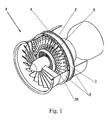
- Fig. 1 schematically shows an engine 3 in a partially sectioned view. Between an outer engine structure 8 and an inner engine structure 10 there is the so-called bypass duct 2 or bypass, over which flows the cold part of the air flow. From the inner engine structure 10, the core engine itself and the hot engine power is enclosed. At the front opening of the engine 3 are rotating blades. Behind this is the vane assembly 1 which fixes between the outer engine structure 8 and the inner engine structure 10 is.
- the vanes 6 (see Fig. 2 ) of the vane assembly 1 serve to transform the energy supplied by the rotor in the form of a higher flow velocity in the circumferential direction into usable work (pressure increase, advance).
- the vane assembly 1 consists of an outer ring 4 and an inner ring 5 and vanes 6 interposed therebetween.
- connecting elements 7 and the inner ring 5 on the outer ring 4 of the vane assembly there are connecting elements 7 and the inner ring 5 on the outer ring 4 of the vane assembly the guide vane assembly 1 connecting elements 9 (see Fig. 2 ) arranged.
- These connecting elements 7, 9 may in the simplest case be formed by bores through which corresponding bolts, screws or the like are placed for connecting the vane arrangement 1 to the engine structures 8, 10 (see FIG Fig. 2 ).
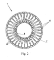
- Fig. 2 shows the front view of a vane assembly 1 according to the present invention.
- the guide vane assembly 1 is divided into a plurality of segments 11, wherein each segment 11 is at least one guide vane 6 with a part 12 of the outer ring 4 and a part 13 of the inner ring 5 integrally preferably made of fiber-reinforced plastic composite material (see Fig. 3a and 3b ).
- the dargillon embodiment of the vane assembly 1 consists of 32 segments, each with a vane 6. Of course, fewer or more segments 11 may be provided and also more than one vane 6 are arranged per segment 11. However, the production of a segment 11 with two or more vanes 6 is associated with higher costs.
- the Fig. 3a and 3b show two different views on a segment 11 of a vane assembly 1.
- the segment 11 includes a portion 12 of the outer ring 4 of the vane assembly 1 according to Fig. 2 a vane 6 and a part 13 of the inner ring 5 of the vane assembly 1 according to Fig. 2 ,
- two flanges 14, 15 are arranged both on the ring part 12 and on the ring part 13, via which the segment 11 can be connected to the outer engine structure 8 and the inner engine structure 10 (not shown).
- 10 preferably bores 16, 17 are arranged on the flanges 14, 15. Through these holes 16, 17 corresponding bolts, screws or the like.
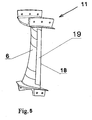
- 10 are arranged on one edge of the guide vane 6, in particular on the airflow related to the leading edge 18 of the guide vane 6, or surface a coating or a protective element 19 (s. Fig. 5 ) can be arranged.
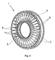
- Fig. 4 shows a perspective view of the vane assembly 1 according to the present invention.
- the segments 11 of the vane assembly 1 are not necessarily connected to each other, but can also be glued or releasably connected via corresponding connecting elements (not shown) with each other.
- Fig. 5 shows a perspective view of a further embodiment of a segment 11 of a vane assembly 1, in which at the front edge 18 of the guide vane 6, a protective element 19 is arranged, for example glued.
- vane assembly according to the invention which is made of pure fiber-reinforced plastic composite material, engines with lower weight can be manufactured and repaired by the interchangeability of individual segments 11 easier and faster.
Landscapes
- Engineering & Computer Science (AREA)
- Mechanical Engineering (AREA)
- General Engineering & Computer Science (AREA)
- Chemical & Material Sciences (AREA)
- Materials Engineering (AREA)
- Composite Materials (AREA)
- Structures Of Non-Positive Displacement Pumps (AREA)
- Moulding By Coating Moulds (AREA)
- Shafts, Cranks, Connecting Bars, And Related Bearings (AREA)
- Fluid-Damping Devices (AREA)
- Fishing Rods (AREA)
Description
- Die Erfindung betrifft eine Leitschaufelanordnung zur Umlenkung der Strömung im Nebenstromkanal eines Triebwerks, mit einem äußeren Ring und einem inneren Ring und dazwischen im Wesentlichen radial angeordneten Leitschaufeln, wobei der äußere Ring Elemente zur Verbindung mit einer äußeren Triebwerksstruktur und der innere Ring Elemente zur Verbindung mit einer inneren Triebwerksstruktur aufweist, wobei mehrere Segmente vorgesehen sind.
- Die Erfindung ist insbesondere auf Strahltriebwerke wie sie bei Flugzeugen, insbesondere großen Passagier- oder Frachtflugzeugen, verwendet werden, gerichtet. Das Strahltriebwerk arbeitet nach dem Prinzip des Rückstoßantriebes, wobei die Umgebungsluft angesaugt und als Antriebsstrahl ausgestoßen wird. Um das Triebwerk ist ein so genannter ringförmiger Nebenstromkanal angeordnet, durch den ein Teil der Luft strömt. Dieser Nebenstromkanal oder Bypass wird von der inneren Triebwerksstruktur, welche das Kerntriebwerk umschließt, und die äußere Triebwerksstruktur begrenzt. Zur Umlenkung der Strömung innerhalb des Nebenstromkanals werden Leitschaufeln eingesetzt, die zwischen der inneren und äußeren Triebwerksstruktur angeordnet sind. Üblicherweise sind diese Leitschaufeln aus Metall, insbesondere Titan, gebildet und mit der inneren und äußeren Triebwerksstruktur entsprechend verbunden.
- Zur Erzielung der erforderlichen Stabilität sind üblicherweise zusätzliche Elemente zwischen der inneren und äußeren Triebwerksstruktur angeordnet. Diese zusätzlichen Streben erhöhen den Herstellungsaufwand wie auch das Gewicht des gesamten Triebwerks und verschlechtern die aerodynamische Güte im Bypass.
- Eines der obersten Ziele in der Luftfahrttechnik ist die Gewichtsreduktion und in der Folge die Treibstoffeinsparung. Aus diesem Grund werden zahlreiche Bestandteile eines Flugzeuges anstelle aus Metall aus Kunststoffverbundwerkstoffen hergestellt. Entwicklungstrends zielen auf den Einsatz von faserverstärkten Kunststoffverbundwerkstoffen auch im Strukturbereich ab. Auch im Bereich der Triebwerksstruktur ist man bestrebt, Bestandteile aus den leichteren faserverstärkten Kunststoffverbundwerkstoffen herzustellen und dadurch Gewicht einzusparen.
- Beispielsweise zeigt die
US 4,596,621 A ein Verfahren zur Herstellung einer so genannten Kaskade, wie sie beim Schubumkehrmechanismus in Triebwerken verwendet wird, aus faserverstärkten Kunststoffverbundwerkstoffen. Insbesondere bei Bauteilen komplexer Geometrie ist die nicht oder nur teilweise automatisierbare Herstellung in Kunststoffverbundwerkstoffen jedoch nicht wirtschaftlich. - Auch die
US 5,624,618 A beschreibt ein Verfahren zur Bildung von Bauteilen komplexer Geometrie aus Verbundwerkstoffen, wobei auch hier die so genannten Kaskaden, über welche bei der Schubumkehr die Luft in die entgegengesetzte Richtung gelenkt wird, erwähnt werden. Im Gegensatz zur gegenständlichen Leitschaufelanordnung werden an die Kaskaden gemäß derUS 5,624,618 A nicht so hohe Anforderungen hinsichtlich Stabilität gestellt. - Die
DE 103 23 132 A1 beschreibt eine verstellbare Leitschaufel aus faserverstärktem Kunststoff und ein Verfahren zur Herstellung der selben. - Eine Leitschaufelanordnung der gegenständlichen Art ist beispielsweise aus der
EP 1 167 693 B1 bekannt, wobei die Leitschaufeln an ihren Enden mit aerodynamischen Verkleidungen versehen sind, welche die Elemente zur Verbindung mit dem äußeren und inneren Ring der Triebwerksstruktur enthalten. Dementsprechend ist die Befestigung der Segmente relativ aufwändig und muss durch radial angebrachte Verbindungselemente vorgenommen werden. - Auch bei der Leitschaufelanordnung gemäß der
US 5 584 654 A ist die Befestigung der einzelnen Segmente mit einem relativ hohen Aufwand verbunden. - Die Konstruktion gemäß der
GB 2 418 460 A - Die Aufgabe der vorliegenden Erfindung ist die Schaffung einer Leitschaufelanordnung der gegenständlichen Art, welche sowohl die aerodynamischen als auch die statischen Aufgaben erfüllt und möglichst niedriges Gewicht aufweist. Die Leitschaufelanordnung soll daher integral herstellbar sein und darüber hinaus rasch austauschbar sein. Nachteile bekannter Leitschaufelanordnungen sollen vermieden oder zumindest reduziert werden.
- Gelöst wird die erfindungsgemäße Aufgabe dadurch, dass jedes Segment zumindest aus einer Leitschaufel mit einem Teil des äußeren Rings mit zumindest zwei Flanschen zur Befestigung mit der äußeren Triebwerksstruktur und einem Teil des inneren Rings mit zumindest zwei Flanschen zur Befestigung mit der inneren Triebwerksstruktur einstückig hergestellt ist, und dass die Segmente aus faserverstärktem Kunststoff hergestellt sind, und dass zumindest ein Großteil der Fasern jedes Segments durchgehend von den Flanschen des äußeren Ringteils über die zumindest eine Leitschaufel zu den Flanschen des inneren Ringteils durch mehrfache Umlenkung angeordnet ist. Durch die Trennung der Leitschaufelanordnung in mehrere Segmente können diese trotz der komplexen Geometrien relativ einfach und rasch hergestellt werden. Eine voll integrale Leitschaufelanordnung für ein Strahltriebwerk einer Passagiermaschine, welche Dimensionen von mehreren Metern umfasst, wäre technisch und ökonomisch derzeit nicht herstellbar. Dadurch, dass jedes Segment zumindest aus einer Leitschaufel mit einem Teil des äußeren Rings und einem Teil des inneren Rings einstückig hergestellt ist, erfüllt jedes Segment der Leitschaufelanordnung die erforderliche statische Aufgabe, weshalb keine weiteren Streben zwischen äußerer und innerer Triebwerksstruktur erforderlich sind. Dies bewirkt wiederum eine Reduktion des Gesamtgewichts des Triebwerks. Über die vorzugsweise in Umfangsrichtung des Triebwerks orientierten Flansche können die Segmente besonders einfach mit der inneren und äußeren Triebwerksstruktur verbunden und entsprechend fixiert werden. Durch die Integration der Flansche in den Segmenten werden die Befestigungselemente in der Leitschaufelanordnung integriert. Verbindungen zwischen den Komponenten der Leitschaufelanordnung entfallen grundsätzlich, können aber je nach Steifigkeitsanforderung vorgesehen bzw. notwendig sein. Durch den Einbau der Leitschaufelanordnung im Triebwerk wird die notwendige Stabilität erreicht und es können die auftretenden Triebwerkslasten an die Flugzeugzelle übertragen werden. Ein weiterer Vorteil in der Aufteilung der Leitschaufelanordnung in mehrere Segmente besteht darin, dass bei Beschädigung eines Teils der Leitschaufelanordnung nur das betroffene Segment bzw. die betroffenen Segmente ausgetauscht werden muss bzw. müssen und nicht die gesamte Leitschaufelanordnung repariert werden muss. Aufgrund der Verwendung eines faserverstärkten Kunststoffverbundwerkstoffs für die Segmente kann das Gewicht gegenüber herkömmlichen Bauweisen aus Metall deutlich reduziert werden. Moderne faserverstärkte Kunststoffverbundwerkstoffe halten auch den im Nebenstromkanal eines Triebwerks auftretenden Temperaturen von üblicherweise 100-130°C ohne weiteres Stand. Die gegenständliche Leitschaufelanordnung besteht aus reinem faserverstärkten Kunststoffverbundwerkstoff und erfüllt sowohl die statischen als auch die aerodynamischen Aufgaben. Dadurch, dass zumindest ein Großteil der Fasern jedes Segments durchgehend von den Flanschen des äußeren Ringteils über die zumindest eine Leitschaufel zu den Flanschen des inneren Ringteils durch mehrfache Umlenkung angeordnet ist, kann eine ausreichend hohe Festigkeit, insbesondere bei Leitschaufelanordnungen für besonders große Triebwerke, erzielt werden. Somit werden durchgehende Faserstränge mehrfach umgelenkt, wodurch die Kraft entlang der Faserstränge geleitet werden kann und nicht interlaminar übertragen werden muss. Dies resultiert in einer besonders hohen Festigkeit der Segmente bzw. der gesamten Leitschaufelanordnung, wodurch zusätzliche Streben zwischen der äußeren Triebwerksstruktur und der inneren Triebwerksstruktur entfallen können. Dies schlägt sich wiederum in einem niedrigeren Gesamtgewicht der Anordnung nieder.
- Vorteilhafterweise sind die Segmente der Leitschaufelanordnung aus Kohlenstofffaser-verstärktem Kunststoff hergestellt. Neben dem geringen Gewicht von Kohlenstoffasern weisen diese auch einen besonders niedrigen Temperaturkoeffizienten und eine besonders hohe Gewichts-spezifische Steifigkeit und Festigkeit auf.
- Gemäß einem weiteren Merkmal der Erfindung können im faserverstärkten Kunststoffverbundwerkstoff reaktive Materialien, wie beispielsweise Thermoplastfäden, eingenäht oder eingewebt werden. Dadurch können bestimmte Eigenschaften wie Festigkeit oder Schlagzähigkeit erhöht werden. Beispielsweise kann das verwendete Carbongewebe mit Thermoplastfäden verwebt werden und nach Zugabe des Harzes das Thermoplastmaterial aufgelöst werden, wodurch die Schlagzähigkeit erhöht wird.
- Weiters können Vernähungen im faserverstärkten Kunststoffverbundwerkstoff im Wesentlichen quer zur Lagenrichtung vorgesehen sein, durch welche die interlaminare Kraftübertragung verbessert werden kann. Zur Vernähung eignen sich Glasfasern, Kohlefasern, Fasern aus Kevlar® oder verschiedene Garne.
- Die Segmente können in Harzinjektionsverfahren hergestellt werden, wobei sich insbesondere das RTM (Resin Transfer Moulding)- und das VARTM (Vakuum Assisted RTM)-Verfahren eignen. Bei derartigen Herstellungsverfahren werden die trockenen Fasern in eine geschlossene Form eingelegt, die Form evakuiert und das flüssige Harz allenfalls unter Druck injiziert. Durch Wärme wird das Harz ausgehärtet.
- Um eine möglichst rasche und einfache Befestigung der Segmente der Leitschaufelanordnung an der äußeren bzw. inneren Triebwerksstruktur zu ermöglichen, sind in den Flanschen mehrere Bohrungen zur Aufnahme von Bolzen oder dgl. als Elemente zur Verbindung mit den Triebwerksstrukturen angeordnet.
- Es ist nicht erforderlich, die Segmente der Leitschaufelanordnung untereinander zu verbinden. Natürlich ist es jedoch möglich, eine Verbindung zwischen den Segmenten vorzusehen. Dabei können die Segmente untereinander verklebt werden oder auch über entsprechende Verbindungselemente wie z.B. Bolzen, Schrauben oder dgl. lösbar miteinander verbunden werden.
- Zur Erhöhung der Steifigkeit bei gleichzeitig möglichst niedrigem Gewicht können an den Flanschen der Segmente Versteifungselemente aus faserverstärktem Kunststoff angeordnet und mit diesen integriert sein.
- Zum Schutz der Segmente der Leitschaufelanordnung können an den Segmenten Beschichtungen oder Schutzelemente angeordnet sein. Vorteilhafterweise sind diese Beschichtungen oder Schutzelemente an Kanten der zumindest einen Leitschaufel jedes Segments, insbesondere an der auf den Luftstrom bezogenen Vorderkante der Leichtschaufel, angeordnet. Diese Beschichtungen oder Schutzelemente können beispielsweise aus Metall gebildet sein. Die Schutzelemente können an die Kante, insbesondere Vorderkante der zumindest einen Leitschaufel jedes Segments aufgeklebt sein.
- Die vorliegende Erfindung wird anhand der beigefügten Zeichnungen näher erläutert.
- Darin zeigen
-
Fig. 1 eine schematische Ansicht auf ein Triebwerk in geschnittener Darstellung; -
Fig. 2 die Draufsicht auf eine Leitschaufelanordnung gemäß der vorliegenden Erfindung; -
Fig. 3a und 3b zwei verschiedene perspektivische Ansichten auf ein erfindungsgemäßes Segment einer Leitschaufelanordnung; -
Fig. 4 eine perspektivische Ansicht auf eine Leitschaufelanordnung gemäß der vorliegenden Erfindung; und -
Fig. 5 eine perspektivische Ansicht auf eine weitere Ausführungsform eines Segments einer Leitschaufelanordnung gemäß der vorliegenden Erfindung. -
Fig. 1 zeigt schematisch ein Triebwerk 3 in teilweise geschnittener Darstellung. Zwischen einer äußeren Triebwerksstruktur 8 und einer inneren Triebwerksstruktur 10 befindet sich der so genannte Nebenstromkanal 2 bzw. Bypass, über den der kalte Teil der Luftströmung strömt. Von der inneren Triebwerksstruktur 10 ist das Kerntriebwerk selbst und der heiße Triebwerksstrom umschlossen. An der vorderen Öffnung des Triebwerks 3 befinden sich rotierende Laufschaufeln. Hinter diesem befindet sich die Leitschaufelanordnung 1, welche fix zwischen der äußeren Triebwerksstruktur 8 und der inneren Triebwerksstruktur 10 befestigt ist. Die Leitschaufeln 6 (sieheFig. 2 ) der Leitschaufelanordnung 1 dienen dazu, die vom Rotor in Form einer höheren Strömungsgeschwindigkeit in Umfangsrichtung zugeführte Energie in nutzbare Arbeit (Druckerhöhung, Vortrieb) umzuformen. Die Leitschaufelanordnung 1 besteht aus einem äußeren Ring 4 und einem inneren Ring 5 und dazwischen angeordneten Leitschaufeln 6. Zur Verbindung der Leitschaufelanordnung 1 mit der äußeren Triebwerksstruktur 8 und der inneren Triebwerksstruktur 10 sind am äußeren Ring 4 der Leitschaufelanordnung 1 Verbindungselemente 7 und am inneren Ring 5 der Leitschaufelanordnung 1 Verbindungselemente 9 (sieheFig. 2 ) angeordnet. Diese Verbindungselemente 7, 9 können im einfachsten Fall durch Bohrungen gebildet sein, durch die entsprechende Bolzen, Schrauben oder dgl. zur Verbindung der Leitschaufelanordnung 1 mit den Triebwerksstrukturen 8, 10 platziert werden (sieheFig. 2 ). -
Fig. 2 zeigt die Vorderansicht auf eine Leitschaufelanordnung 1 gemäß der vorliegenden Erfindung. Dabei ist die Leitschaufelanordnung 1 in mehrere Segmente 11 unterteilt, wobei jedes Segment 11 zumindest aus einer Leitschaufel 6 mit einem Teil 12 des äußeren Rings 4 und einem Teil 13 des inneren Rings 5 einstückig vorzugsweise aus faserverstärktem Kunststoffverbundwerkstoff hergestellt ist (sieheFig. 3a und 3b ). Die dargstellte Ausführungsform der Leitschaufelanordnung 1 besteht aus 32 Segmenten mit jeweils einer Leitschaufel 6. Natürlich können auch weniger oder mehr Segmente 11 vorgesehen sein und auch pro Segment 11 mehr als eine Leitschaufel 6 angeordnet werden. Die Herstellung eines Segments 11 mit zwei oder mehr Leitschaufeln 6 ist jedoch mit höherem Aufwand verbunden. - Die
Fig. 3a und 3b zeigen zwei verschiedene Ansichten auf ein Segment 11 einer Leitschaufelanordnung 1. Das Segment 11 beinhaltet einen Teil 12 des äußeren Rings 4 der Leitschaufelanordnung 1 gemäßFig. 2 einer Leitschaufel 6 und einen Teil 13 des inneren Rings 5 der Leitschaufelanordnung 1 gemäßFig. 2 . Zusätzlich sind sowohl am Ringteil 12 als auch am Ringteil 13 jeweils zwei Flansche 14, 15 angeordnet, über die das Segment 11 mit der äußeren Triebwerksstruktur 8 und der inneren Triebwerksstruktur 10 (nicht dargestellt) verbunden werden kann. Zur Verbindung des Segments 11 mit den Triebwerksstrukturen 8, 10 sind vorzugsweise Bohrungen 16, 17 an den Flanschen 14, 15 angeordnet. Durch diese Bohrungen 16, 17 können entsprechende Bolzen, Schrauben oder dgl. zur Befestigung mit der entsprechenden Struktur an der Triebwerksstruktur 8, 10 angeordnet werden. Schließlich kann an einer Kante der Leitschaufel 6, insbesondere an der auf den Luftstrom bezogenen Vorderkante 18 der Leitschaufel 6, oder flächig eine Beschichtung oder ein Schutzelement 19 (s.Fig. 5 ) angeordnet sein. -
Fig. 4 zeigt eine perspektivische Ansicht auf die Leitschaufelanordnung 1 gemäß der vorliegenden Erfindung. Die Segmente 11 der Leitschaufelanordnung 1 sind untereinander nicht zwingend verbunden, können jedoch auch verklebt oder lösbar über entsprechende Verbindungselemente (nicht dargestellt) miteinander verbunden sein. -
Fig. 5 zeigt eine perspektivische Ansicht auf eine weitere Ausführungsform eines Segments 11 einer Leitschaufelanordnung 1, bei der an der Vorderkante 18 der Leitschaufel 6 ein Schutzelement 19 angeordnet, beispielsweise aufgeklebt ist. - Durch die erfindungsgemäße Leitschaufelanordnung, welche aus reinem faserverstärkten Kunststoffverbundwerkstoff hergestellt ist, können Triebwerke mit niedrigerem Gewicht hergestellt werden und durch die Austauschbarkeit einzelner Segmente 11 leichter und rascher repariert werden.
Claims (15)
- Leitschaufelanordnung (1) zur Umlenkung der Strömung im Nebenstromkanal (2) eines Triebwerks (3), mit einem äußeren Ring (4) und einem inneren Ring (5) und dazwischen im Wesentlichen radial angeordneten Leitschaufeln (6), wobei der äußere Ring (4) Elemente (7) zur Verbindung mit einer äußeren Triebwerksstruktur (8) und der innere Ring (5) Elemente (9) zur Verbindung mit einer inneren Triebwerksstruktur (10) aufweist, wobei mehrere Segmente (11) vorgesehen sind, wobei jedes Segment (11) zumindest aus einer Leitschaufel (6) mit einem Teil (12) des äußeren Rings (4) mit zumindest zwei Flanschen (14) zur Befestigung mit der äußeren Triebwerksstruktur (8) und einem Teil (13) des inneren Rings (5) mit zumindest zwei Flanschen (15) zur Befestigung mit der inneren Triebwerksstruktur (10) einstückig hergestellt ist, dadurch gekennzeichnet dass die Segmente (11) aus faserverstärktem Kunststoff hergestellt sind, und dass zumindest ein Großteil der Fasern jedes Segments (11) durchgehend von den Flanschen (14) des äußeren Ringteils (12) über die zumindest eine Leitschaufel (6) zu den Flanschen (15) des inneren Ringteils (13) durch mehrfache Umlenkung angeordnet ist.
- Anordnung (1) nach Anspruch 1, dadurch gekennzeichnet, dass die Segmente (11) aus Kohlenstofffaser-verstärktem Kunststoff hergestellt sind.
- Anordnung (1) nach Anspruch 1 oder 2, dadurch gekennzeichnet, dass im faserverstärkten Kunststoffverbundwerkstoff reaktive Materialien, wie beispielsweise Thermoplastfäden, eingenäht oder eingewebt sind.
- Anordnung (1) nach einem der Ansprüche 1 bis 3, dadurch gekennzeichnet, dass Vernähungen im faserverstärkten Kunststoffverbundwerkstoff im Wesentlichen quer zur Lagenrichtung vorgesehen sind.
- Anordnung (1) nach einem der Ansprüche 1 bis 4, dadurch gekennzeichnet, dass jedes Segment (11) in Harzinjektionsverfahren hergestellt ist.
- Anordnung (1) nach Anspruch 5, dadurch gekennzeichnet, dass jedes Segment (11) im RTM (Resin Transfer Moulding)-Verfahren hergestellt ist.
- Anordnung (1) nach Anspruch 5, dadurch gekennzeichnet, dass jedes Segment (11) im VARTM (Vakuum Assisted RTM)-Verfahren hergestellt ist.
- Anordnung (1) nach einem der Ansprüche 1 bis 7, dadurch gekennzeichnet, dass in den Flanschen (14, 15) mehrere Bohrungen (16, 17) zur Aufnahme von Bolzen oder dgl. als Elemente (7, 9) zur Verbindung mit den Triebwerksstrukturen (8, 10) angeordnet sind.
- Anordnung (1) nach einem der Ansprüche 1 bis 8, dadurch gekennzeichnet, dass die Segmente (11) miteinander verbunden sind.
- Anordnung (1) nach Anspruch 9, dadurch gekennzeichnet, dass die Segmente (11) miteinander verklebt sind.
- Anordnung (1) nach Anspruch 9, dadurch gekennzeichnet, dass die Segmente (11) über Verbindungselemente, wie z.B. Bolzen, Schrauben oder dgl., lösbar miteinander verbunden sind.
- Anordnung (1) nach einem der Ansprüche 1 bis 11, dadurch gekennzeichnet, dass an den Flanschen (14, 15) der Segmente (11) Versteifungselemente aus faserverstärktem Kunststoff angeordnet sind.
- Anordnung (1) nach einem der Ansprüche 1 bis 12, dadurch gekennzeichnet, dass an den Segementen (11) Beschichtungen oder Schutzelemente (19) angeordnet sind.
- Anordnung (1) nach Anspruch 13, dadurch gekennzeichnet, dass an Kanten der zumindest einen Leitschaufel (6) jedes Segments (11), insbesondere an der auf den Luftstrom bezogenen Vorderkante (18), Beschichtungen angeordnet sind.
- Anordnung (1) nach Anspruch 13, dadurch gekennzeichnet, dass an Kanten der zumindest einen Leitschaufel (6) jedes Segments (11), insbesondere an der auf den Luftstrom bezogenen Vorderkante (18), Schutzelemente (19) angeordnet sind.
Applications Claiming Priority (2)
| Application Number | Priority Date | Filing Date | Title |
|---|---|---|---|
| AT0110506A AT503840B1 (de) | 2006-06-30 | 2006-06-30 | Leitschaufelanordnung für ein triebwerk |
| PCT/AT2007/000325 WO2008000014A2 (de) | 2006-06-30 | 2007-06-29 | Leitschaufelanordnung für ein triebwerk |
Publications (2)
| Publication Number | Publication Date |
|---|---|
| EP2035658A2 EP2035658A2 (de) | 2009-03-18 |
| EP2035658B1 true EP2035658B1 (de) | 2010-07-28 |
Family
ID=38719805
Family Applications (1)
| Application Number | Title | Priority Date | Filing Date |
|---|---|---|---|
| EP07763725A Active EP2035658B1 (de) | 2006-06-30 | 2007-06-29 | Leitschaufelanordnung für ein triebwerk |
Country Status (8)
| Country | Link |
|---|---|
| US (1) | US8297934B2 (de) |
| EP (1) | EP2035658B1 (de) |
| CN (1) | CN101484663B (de) |
| AT (2) | AT503840B1 (de) |
| CA (1) | CA2652953C (de) |
| DE (1) | DE502007004583D1 (de) |
| ES (1) | ES2347835T3 (de) |
| WO (1) | WO2008000014A2 (de) |
Families Citing this family (43)
| Publication number | Priority date | Publication date | Assignee | Title |
|---|---|---|---|---|
| FR2933130B1 (fr) * | 2008-06-25 | 2012-02-24 | Snecma | Carter structural pour turbomachine |
| RU2387883C1 (ru) * | 2008-10-20 | 2010-04-27 | Открытое акционерное общество Научно-производственное объединение "Искра" | Рабочее колесо центробежного компрессора |
| EP2199544B1 (de) * | 2008-12-22 | 2016-03-30 | Techspace Aero S.A. | Aufbau einer Leitschaufelstufe |
| FR2946999B1 (fr) * | 2009-06-18 | 2019-08-09 | Safran Aircraft Engines | Element de distributeur de turbine en cmc, procede pour sa fabrication, et distributeur et turbine a gaz l'incorporant. |
| EP2264284B1 (de) | 2009-06-18 | 2015-01-28 | Techspace Aero S.A. | Verfahren zur Herstellung eines Leitschaufelkranzes und ein nach diesem Verfahren erhaltener Gleichrichter |
| US8850823B2 (en) | 2009-12-29 | 2014-10-07 | Rolls-Royce North American Technologies, Inc. | Integrated aero-engine flowpath structure |
| EP2371521B1 (de) * | 2010-04-02 | 2014-07-02 | Techspace Aero S.A. | Verfahren zur Herstellung eines Gleichrichters |
| US9151166B2 (en) | 2010-06-07 | 2015-10-06 | Rolls-Royce North American Technologies, Inc. | Composite gas turbine engine component |
| JP5569194B2 (ja) * | 2010-07-02 | 2014-08-13 | 株式会社Ihi | シュラウドセグメントの製造方法 |
| FR2964427B1 (fr) | 2010-09-06 | 2014-05-09 | Messier Dowty Sa | Carter de turboreacteur et turboreacteur recevant de tels carters |
| FR2964411B1 (fr) * | 2010-09-06 | 2012-08-24 | Messier Dowty Sa | Aube de turboreacteur, notamment une aube de redresseur, et turboreacteur recevant de telles aubes |
| DE102011086775A1 (de) * | 2011-07-20 | 2013-01-24 | Mtu Aero Engines Gmbh | Verfahren zur Herstellung eines Einlaufbelags, Einlaufsystem, Strömungsmaschine sowie Leitschaufel |
| FR2978495B1 (fr) * | 2011-07-25 | 2013-08-02 | Snecma | Carter, notamment carter intermediaire, de turboreacteur |
| US20130052004A1 (en) † | 2011-08-25 | 2013-02-28 | Nicholas D. Stilin | Structural composite fan exit guide vane for a turbomachine |
| FR2983261B1 (fr) * | 2011-11-24 | 2014-11-28 | Aircelle Sa | Aube de redressement de flux d'air pour moteur d'aeronef et structure de redressement de flux associee |
| FR2983519B1 (fr) * | 2011-12-01 | 2015-07-24 | Snecma Propulsion Solide | Aube de turbine a pale creuse en materiau composite, turbine ou compresseur ayant un distributeur ou redresseur forme de telles aubes et turbomachine les comprenant |
| FR2989608B1 (fr) * | 2012-04-24 | 2015-01-30 | Snecma | Procede d'usinage du bord de fuite d'une aube de turbomachine |
| GB201215908D0 (en) * | 2012-09-06 | 2012-10-24 | Rolls Royce Plc | Fan blade |
| GB201215906D0 (en) * | 2012-09-06 | 2012-10-24 | Rolls Royce Plc | Guide vane assembly |
| US9670790B2 (en) * | 2012-09-28 | 2017-06-06 | United Technologies Corporation | Turbine vane with mistake reduction feature |
| WO2014163667A1 (en) | 2013-03-11 | 2014-10-09 | United Technologies Corporation | Structural guide vane sonic shape and inspection |
| WO2015017001A2 (en) * | 2013-05-14 | 2015-02-05 | General Electric Company | Composite woven outlet guide with optional hollow airfoil |
| CN103511331A (zh) * | 2013-10-18 | 2014-01-15 | 柳州市双铠工业技术有限公司 | 离心泵 |
| CN103707503B (zh) * | 2013-12-12 | 2016-04-06 | 西安航空动力股份有限公司 | 用于将叶片与发动机机匣内环固定的装置及固定方法 |
| FR3021349B1 (fr) | 2014-05-22 | 2021-07-02 | Herakles | Procede de fabrication d'une aube de turbomachine en materiau composite, aube ainsi obtenue et turbomachine l'incorporant |
| US10589475B2 (en) | 2014-09-23 | 2020-03-17 | General Electric Company | Braided blades and vanes having dovetail roots |
| JP6525130B2 (ja) * | 2014-10-07 | 2019-06-05 | 株式会社Ihi | 静翼構造及びこれを用いたターボファンエンジン |
| JP6428128B2 (ja) * | 2014-10-08 | 2018-11-28 | 株式会社Ihi | 静翼構造、及びターボファンエンジン |
| US10202857B2 (en) | 2015-02-06 | 2019-02-12 | United Technologies Corporation | Vane stages |
| FR3063514B1 (fr) * | 2017-03-02 | 2019-04-12 | Safran | Aube de turbomachine et procede pour sa fabrication |
| FR3072607B1 (fr) * | 2017-10-23 | 2019-12-20 | Safran Aircraft Engines | Turbomachine comprenant un ensemble de redressement |
| CN110030037B (zh) * | 2018-01-11 | 2021-08-13 | 中国航发商用航空发动机有限责任公司 | 涡轮导向叶片、涡轮导向叶片组件以及核心机 |
| FR3085416B1 (fr) * | 2018-08-29 | 2020-12-04 | Safran Aircraft Engines | Aube directrice de sortie recomposant une plateforme et une virole de carter intermediaire |
| CN109968241A (zh) * | 2019-04-03 | 2019-07-05 | 哈尔滨汽轮机厂有限责任公司 | 一种汽轮机静叶片整圈预装配盘及预装配方法 |
| FR3098256B1 (fr) * | 2019-07-04 | 2021-10-29 | Dedienne Multiplasturgy Group | Grille composite d’inverseur de poussée à jonctions renforcées de fibres longues |
| US11802485B2 (en) * | 2021-03-03 | 2023-10-31 | Whisper Aero Inc. | Propulsor fan array |
| CA3212144A1 (en) | 2021-03-03 | 2022-09-09 | Whisper Aero Inc. | Propulsor wing trailing edge exhaust area control |
| CN122580002A (zh) * | 2023-09-20 | 2026-08-14 | 耳语航空公司 | 空气移动装置、气动转子和方法 |
| CN119957320B (zh) * | 2023-11-07 | 2026-03-24 | 中国航发商用航空发动机有限责任公司 | 一种轻量化降噪叶片、叶片轻量化降噪设计方法 |
| US12576601B2 (en) * | 2024-01-30 | 2026-03-17 | General Electric Company | Composite structure for a turbine engine |
| US12703156B2 (en) | 2024-05-08 | 2026-08-11 | General Electric Company | Method of manufacturing a composite component for a gas turbine engine |
| DE102024128303A1 (de) * | 2024-09-30 | 2026-04-02 | Rolls-Royce Deutschland Ltd & Co Kg | Frontstruktur für eine Verdichtervorrichtung eines Gasturbinentriebwerks, ein Verfahren zur Herstellung einer Frontstruktur und ein Gasturbinentriebwerk |
| CN121654488B (zh) * | 2026-02-05 | 2026-06-16 | 中国航发湖南动力机械研究所 | 一种带包容机匣的复合材料静子叶片环 |
Family Cites Families (16)
| Publication number | Priority date | Publication date | Assignee | Title |
|---|---|---|---|---|
| US4596621A (en) | 1984-01-03 | 1986-06-24 | The Boeing Company | Method of making a composite bond cascade for a thrust reverser unit of an aircraft engine nacelle |
| FR2654463A1 (fr) * | 1989-11-15 | 1991-05-17 | Snecma | Element de stator de turbomachine. |
| US5226789A (en) * | 1991-05-13 | 1993-07-13 | General Electric Company | Composite fan stator assembly |
| CA2102239C (en) * | 1991-05-24 | 1995-12-26 | Thomas P. Forman | Braided complex composite parts and methods of forming same |
| US5584654A (en) * | 1995-12-22 | 1996-12-17 | General Electric Company | Gas turbine engine fan stator |
| JP4060981B2 (ja) * | 1998-04-08 | 2008-03-12 | 本田技研工業株式会社 | ガスタービンの静翼構造体及びそのユニット |
| US6371725B1 (en) * | 2000-06-30 | 2002-04-16 | General Electric Company | Conforming platform guide vane |
| FR2817192B1 (fr) * | 2000-11-28 | 2003-08-08 | Snecma Moteurs | Ensemble forme par au moins une pale et une plate-forme de fixation de la pale, pour une turbomachine, et procede pour sa fabrication |
| DE10323132B4 (de) * | 2003-05-22 | 2006-10-26 | Mtu Aero Engines Gmbh | Verstellbare Leitschaufel und Verfahren zur Herstellung derselben |
| GB2418460A (en) | 2004-09-22 | 2006-03-29 | Rolls Royce Plc | Aerofoil with low density |
| FR2882394B1 (fr) * | 2005-02-22 | 2007-05-18 | Snecma Moteurs Sa | Dispositif de variation de la section de col d'un distributeur de turbine |
| JP4860941B2 (ja) * | 2005-04-27 | 2012-01-25 | 本田技研工業株式会社 | 整流部材ユニット及びその製造方法 |
| US7874794B2 (en) * | 2006-03-21 | 2011-01-25 | General Electric Company | Blade row for a rotary machine and method of fabricating same |
| FR2925107B1 (fr) * | 2007-12-14 | 2010-01-22 | Snecma | Distributeur sectorise pour une turbomachine |
| US8281604B2 (en) * | 2007-12-17 | 2012-10-09 | General Electric Company | Divergent turbine nozzle |
| US8313291B2 (en) * | 2007-12-19 | 2012-11-20 | Nuovo Pignone, S.P.A. | Turbine inlet guide vane with scalloped platform and related method |
-
2006
- 2006-06-30 AT AT0110506A patent/AT503840B1/de not_active IP Right Cessation
-
2007
- 2007-06-29 WO PCT/AT2007/000325 patent/WO2008000014A2/de not_active Ceased
- 2007-06-29 US US12/306,955 patent/US8297934B2/en active Active
- 2007-06-29 AT AT07763725T patent/ATE475780T1/de active
- 2007-06-29 CN CN2007800248679A patent/CN101484663B/zh active Active
- 2007-06-29 EP EP07763725A patent/EP2035658B1/de active Active
- 2007-06-29 DE DE502007004583T patent/DE502007004583D1/de active Active
- 2007-06-29 ES ES07763725T patent/ES2347835T3/es active Active
- 2007-06-29 CA CA2652953A patent/CA2652953C/en active Active
Also Published As
| Publication number | Publication date |
|---|---|
| WO2008000014A2 (de) | 2008-01-03 |
| US20090317246A1 (en) | 2009-12-24 |
| CA2652953C (en) | 2015-05-19 |
| ATE475780T1 (de) | 2010-08-15 |
| AT503840B1 (de) | 2010-09-15 |
| ES2347835T3 (es) | 2010-11-04 |
| CA2652953A1 (en) | 2008-01-03 |
| WO2008000014A3 (de) | 2008-02-21 |
| DE502007004583D1 (de) | 2010-09-09 |
| CN101484663A (zh) | 2009-07-15 |
| CN101484663B (zh) | 2011-10-05 |
| AT503840A1 (de) | 2008-01-15 |
| EP2035658A2 (de) | 2009-03-18 |
| US8297934B2 (en) | 2012-10-30 |
Similar Documents
| Publication | Publication Date | Title |
|---|---|---|
| AT503840B1 (de) | Leitschaufelanordnung für ein triebwerk | |
| EP1832733B1 (de) | Einlaufkonus aus einem Faserverbundwerkstoff für ein Gasturbinenwerk und Verfahren zu dessen Herstellung | |
| EP2904262B1 (de) | Faserverbundbauteil für das rotorblatt einer windturbine | |
| DE69837640T2 (de) | Äusseres Gondelverkleidungspanel einer Triebwerkgondel mit integrierten Führungsschienenverkleidungen und Verfahren zu dessen Herstellung | |
| DE60130824T2 (de) | Nasenhaube aus Faserverbundwerkstoff und Verfahren zu ihrer Herstellung | |
| EP2032830B1 (de) | Führungsträger für triebwerksverkleidungen | |
| DE60023979T2 (de) | Bläserplattform | |
| EP2716544B1 (de) | Verkleidung für Flügelspitze | |
| DE69502988T2 (de) | Anordnung der Blaserschaufeln bei einem Gasturbinentriebwerk | |
| EP3527812B1 (de) | Schubumkehrerkaskade | |
| US20180045207A1 (en) | Fiber composite material and preform and fan blade made therefrom | |
| EP0596386A1 (de) | Verstellbare Leitschaufel aus faserverstärktem Kunststoff | |
| EP2699764B1 (de) | Schaufel für eine thermische strömungsmaschine | |
| DE102011113205A1 (de) | Rotoranordnung | |
| DE112011100312T5 (de) | Verfahren zur Herstellung des Laufrads eines Kreiselverdichters | |
| EP3199451A1 (de) | Nasenkonus für einen fan eines flugtriebwerks | |
| DE69410104T2 (de) | Kanalabdeckung zur führung der flüssigkeit und verfahren zu seiner herstellung | |
| EP3324026A2 (de) | Mischer für ein triebwerk hergestellt aus mindestens einem verbundwerkstoff, herstellungsverfahren und herstellungsvorrichtung | |
| DE102009056533B4 (de) | Flugzeugrumpfbauteil | |
| DE102014215693B4 (de) | Belastungsangepasstes Triebwerkzwischengehäuse in Verbundbauweise und modulares System für ein Triebwerkzwischengehäuse | |
| DE102014208923B4 (de) | Verfahren zur Verbindung eines Triebwerk-Gehäuseelements aus Faserverbundmaterial mit einem metallischen Anschlusselement | |
| EP2230394B1 (de) | Bauteil zum Einsatz in Heißgasströmungen | |
| EP2998515B1 (de) | Füllelemente eines fans einer gasturbine | |
| DE102021214605A1 (de) | Bauteil eines Gasturbinentriebwerks und Verfahren zur Herstellung des Bauteils | |
| DE102019131443B4 (de) | Flügel, der klapp oder verschwenkbar mit einem Körper verbunden ist |
Legal Events
| Date | Code | Title | Description |
|---|---|---|---|
| PUAI | Public reference made under article 153(3) epc to a published international application that has entered the european phase |
Free format text: ORIGINAL CODE: 0009012 |
|
| 17P | Request for examination filed |
Effective date: 20081230 |
|
| AK | Designated contracting states |
Kind code of ref document: A2 Designated state(s): AT BE BG CH CY CZ DE DK EE ES FI FR GB GR HU IE IS IT LI LT LU LV MC MT NL PL PT RO SE SI SK TR |
|
| AX | Request for extension of the european patent |
Extension state: AL BA HR MK RS |
|
| DAX | Request for extension of the european patent (deleted) | ||
| 17Q | First examination report despatched |
Effective date: 20090916 |
|
| GRAJ | Information related to disapproval of communication of intention to grant by the applicant or resumption of examination proceedings by the epo deleted |
Free format text: ORIGINAL CODE: EPIDOSDIGR1 |
|
| GRAP | Despatch of communication of intention to grant a patent |
Free format text: ORIGINAL CODE: EPIDOSNIGR1 |
|
| GRAS | Grant fee paid |
Free format text: ORIGINAL CODE: EPIDOSNIGR3 |
|
| GRAA | (expected) grant |
Free format text: ORIGINAL CODE: 0009210 |
|
| AK | Designated contracting states |
Kind code of ref document: B1 Designated state(s): AT BE BG CH CY CZ DE DK EE ES FI FR GB GR HU IE IS IT LI LT LU LV MC MT NL PL PT RO SE SI SK TR |
|
| REG | Reference to a national code |
Ref country code: GB Ref legal event code: FG4D Free format text: NOT ENGLISH |
|
| REG | Reference to a national code |
Ref country code: CH Ref legal event code: EP |
|
| REG | Reference to a national code |
Ref country code: IE Ref legal event code: FG4D Free format text: LANGUAGE OF EP DOCUMENT: GERMAN |
|
| REF | Corresponds to: |
Ref document number: 502007004583 Country of ref document: DE Date of ref document: 20100909 Kind code of ref document: P |
|
| REG | Reference to a national code |
Ref country code: ES Ref legal event code: FG2A Ref document number: 2347835 Country of ref document: ES Kind code of ref document: T3 |
|
| REG | Reference to a national code |
Ref country code: NL Ref legal event code: VDEP Effective date: 20100728 |
|
| LTIE | Lt: invalidation of european patent or patent extension |
Effective date: 20100728 |
|
| PG25 | Lapsed in a contracting state [announced via postgrant information from national office to epo] |
Ref country code: LT Free format text: LAPSE BECAUSE OF FAILURE TO SUBMIT A TRANSLATION OF THE DESCRIPTION OR TO PAY THE FEE WITHIN THE PRESCRIBED TIME-LIMIT Effective date: 20100728 Ref country code: FI Free format text: LAPSE BECAUSE OF FAILURE TO SUBMIT A TRANSLATION OF THE DESCRIPTION OR TO PAY THE FEE WITHIN THE PRESCRIBED TIME-LIMIT Effective date: 20100728 Ref country code: NL Free format text: LAPSE BECAUSE OF FAILURE TO SUBMIT A TRANSLATION OF THE DESCRIPTION OR TO PAY THE FEE WITHIN THE PRESCRIBED TIME-LIMIT Effective date: 20100728 |
|
| PG25 | Lapsed in a contracting state [announced via postgrant information from national office to epo] |
Ref country code: CY Free format text: LAPSE BECAUSE OF FAILURE TO SUBMIT A TRANSLATION OF THE DESCRIPTION OR TO PAY THE FEE WITHIN THE PRESCRIBED TIME-LIMIT Effective date: 20100728 Ref country code: IS Free format text: LAPSE BECAUSE OF FAILURE TO SUBMIT A TRANSLATION OF THE DESCRIPTION OR TO PAY THE FEE WITHIN THE PRESCRIBED TIME-LIMIT Effective date: 20101128 Ref country code: PL Free format text: LAPSE BECAUSE OF FAILURE TO SUBMIT A TRANSLATION OF THE DESCRIPTION OR TO PAY THE FEE WITHIN THE PRESCRIBED TIME-LIMIT Effective date: 20100728 Ref country code: BG Free format text: LAPSE BECAUSE OF FAILURE TO SUBMIT A TRANSLATION OF THE DESCRIPTION OR TO PAY THE FEE WITHIN THE PRESCRIBED TIME-LIMIT Effective date: 20101028 Ref country code: PT Free format text: LAPSE BECAUSE OF FAILURE TO SUBMIT A TRANSLATION OF THE DESCRIPTION OR TO PAY THE FEE WITHIN THE PRESCRIBED TIME-LIMIT Effective date: 20101129 Ref country code: SI Free format text: LAPSE BECAUSE OF FAILURE TO SUBMIT A TRANSLATION OF THE DESCRIPTION OR TO PAY THE FEE WITHIN THE PRESCRIBED TIME-LIMIT Effective date: 20100728 |
|
| REG | Reference to a national code |
Ref country code: IE Ref legal event code: FD4D |
|
| PG25 | Lapsed in a contracting state [announced via postgrant information from national office to epo] |
Ref country code: LV Free format text: LAPSE BECAUSE OF FAILURE TO SUBMIT A TRANSLATION OF THE DESCRIPTION OR TO PAY THE FEE WITHIN THE PRESCRIBED TIME-LIMIT Effective date: 20100728 Ref country code: SE Free format text: LAPSE BECAUSE OF FAILURE TO SUBMIT A TRANSLATION OF THE DESCRIPTION OR TO PAY THE FEE WITHIN THE PRESCRIBED TIME-LIMIT Effective date: 20100728 Ref country code: GR Free format text: LAPSE BECAUSE OF FAILURE TO SUBMIT A TRANSLATION OF THE DESCRIPTION OR TO PAY THE FEE WITHIN THE PRESCRIBED TIME-LIMIT Effective date: 20101029 |
|
| PG25 | Lapsed in a contracting state [announced via postgrant information from national office to epo] |
Ref country code: IE Free format text: LAPSE BECAUSE OF FAILURE TO SUBMIT A TRANSLATION OF THE DESCRIPTION OR TO PAY THE FEE WITHIN THE PRESCRIBED TIME-LIMIT Effective date: 20100728 Ref country code: DK Free format text: LAPSE BECAUSE OF FAILURE TO SUBMIT A TRANSLATION OF THE DESCRIPTION OR TO PAY THE FEE WITHIN THE PRESCRIBED TIME-LIMIT Effective date: 20100728 |
|
| PG25 | Lapsed in a contracting state [announced via postgrant information from national office to epo] |
Ref country code: CZ Free format text: LAPSE BECAUSE OF FAILURE TO SUBMIT A TRANSLATION OF THE DESCRIPTION OR TO PAY THE FEE WITHIN THE PRESCRIBED TIME-LIMIT Effective date: 20100728 Ref country code: SK Free format text: LAPSE BECAUSE OF FAILURE TO SUBMIT A TRANSLATION OF THE DESCRIPTION OR TO PAY THE FEE WITHIN THE PRESCRIBED TIME-LIMIT Effective date: 20100728 Ref country code: EE Free format text: LAPSE BECAUSE OF FAILURE TO SUBMIT A TRANSLATION OF THE DESCRIPTION OR TO PAY THE FEE WITHIN THE PRESCRIBED TIME-LIMIT Effective date: 20100728 Ref country code: RO Free format text: LAPSE BECAUSE OF FAILURE TO SUBMIT A TRANSLATION OF THE DESCRIPTION OR TO PAY THE FEE WITHIN THE PRESCRIBED TIME-LIMIT Effective date: 20100728 |
|
| PLBE | No opposition filed within time limit |
Free format text: ORIGINAL CODE: 0009261 |
|
| STAA | Information on the status of an ep patent application or granted ep patent |
Free format text: STATUS: NO OPPOSITION FILED WITHIN TIME LIMIT |
|
| 26N | No opposition filed |
Effective date: 20110429 |
|
| REG | Reference to a national code |
Ref country code: DE Ref legal event code: R097 Ref document number: 502007004583 Country of ref document: DE Effective date: 20110429 |
|
| PG25 | Lapsed in a contracting state [announced via postgrant information from national office to epo] |
Ref country code: MT Free format text: LAPSE BECAUSE OF FAILURE TO SUBMIT A TRANSLATION OF THE DESCRIPTION OR TO PAY THE FEE WITHIN THE PRESCRIBED TIME-LIMIT Effective date: 20100728 |
|
| BERE | Be: lapsed |
Owner name: FACC AG Effective date: 20110630 |
|
| REG | Reference to a national code |
Ref country code: CH Ref legal event code: PL |
|
| PG25 | Lapsed in a contracting state [announced via postgrant information from national office to epo] |
Ref country code: BE Free format text: LAPSE BECAUSE OF NON-PAYMENT OF DUE FEES Effective date: 20110630 |
|
| PG25 | Lapsed in a contracting state [announced via postgrant information from national office to epo] |
Ref country code: CH Free format text: LAPSE BECAUSE OF NON-PAYMENT OF DUE FEES Effective date: 20110630 Ref country code: LI Free format text: LAPSE BECAUSE OF NON-PAYMENT OF DUE FEES Effective date: 20110630 |
|
| PG25 | Lapsed in a contracting state [announced via postgrant information from national office to epo] |
Ref country code: MC Free format text: LAPSE BECAUSE OF NON-PAYMENT OF DUE FEES Effective date: 20110630 |
|
| PG25 | Lapsed in a contracting state [announced via postgrant information from national office to epo] |
Ref country code: LU Free format text: LAPSE BECAUSE OF NON-PAYMENT OF DUE FEES Effective date: 20110629 |
|
| PG25 | Lapsed in a contracting state [announced via postgrant information from national office to epo] |
Ref country code: TR Free format text: LAPSE BECAUSE OF FAILURE TO SUBMIT A TRANSLATION OF THE DESCRIPTION OR TO PAY THE FEE WITHIN THE PRESCRIBED TIME-LIMIT Effective date: 20100728 |
|
| PG25 | Lapsed in a contracting state [announced via postgrant information from national office to epo] |
Ref country code: HU Free format text: LAPSE BECAUSE OF FAILURE TO SUBMIT A TRANSLATION OF THE DESCRIPTION OR TO PAY THE FEE WITHIN THE PRESCRIBED TIME-LIMIT Effective date: 20100728 |
|
| REG | Reference to a national code |
Ref country code: FR Ref legal event code: PLFP Year of fee payment: 10 |
|
| REG | Reference to a national code |
Ref country code: FR Ref legal event code: PLFP Year of fee payment: 11 |
|
| REG | Reference to a national code |
Ref country code: FR Ref legal event code: PLFP Year of fee payment: 12 |
|
| P01 | Opt-out of the competence of the unified patent court (upc) registered |
Effective date: 20230522 |
|
| PGFP | Annual fee paid to national office [announced via postgrant information from national office to epo] |
Ref country code: ES Payment date: 20250718 Year of fee payment: 19 |
|
| PGFP | Annual fee paid to national office [announced via postgrant information from national office to epo] |
Ref country code: IT Payment date: 20250630 Year of fee payment: 19 |
|
| PGFP | Annual fee paid to national office [announced via postgrant information from national office to epo] |
Ref country code: GB Payment date: 20260623 Year of fee payment: 20 |
|
| PGFP | Annual fee paid to national office [announced via postgrant information from national office to epo] |
Ref country code: DE Payment date: 20260623 Year of fee payment: 20 |
|
| PGFP | Annual fee paid to national office [announced via postgrant information from national office to epo] |
Ref country code: AT Payment date: 20260609 Year of fee payment: 20 |
|
| PGFP | Annual fee paid to national office [announced via postgrant information from national office to epo] |
Ref country code: FR Payment date: 20260626 Year of fee payment: 20 |