EP2035596B1 - Plasma immersion ion processing for coating of hollow substrates - Google Patents
Plasma immersion ion processing for coating of hollow substrates Download PDFInfo
- Publication number
- EP2035596B1 EP2035596B1 EP08756039.7A EP08756039A EP2035596B1 EP 2035596 B1 EP2035596 B1 EP 2035596B1 EP 08756039 A EP08756039 A EP 08756039A EP 2035596 B1 EP2035596 B1 EP 2035596B1
- Authority
- EP
- European Patent Office
- Prior art keywords
- hollow
- hollow substrate
- coating
- plasma
- substrate
- Prior art date
- Legal status (The legal status is an assumption and is not a legal conclusion. Google has not performed a legal analysis and makes no representation as to the accuracy of the status listed.)
- Active
Links
Images


Classifications
-
- C—CHEMISTRY; METALLURGY
- C23—COATING METALLIC MATERIAL; COATING MATERIAL WITH METALLIC MATERIAL; CHEMICAL SURFACE TREATMENT; DIFFUSION TREATMENT OF METALLIC MATERIAL; COATING BY VACUUM EVAPORATION, BY SPUTTERING, BY ION IMPLANTATION OR BY CHEMICAL VAPOUR DEPOSITION, IN GENERAL; INHIBITING CORROSION OF METALLIC MATERIAL OR INCRUSTATION IN GENERAL
- C23C—COATING METALLIC MATERIAL; COATING MATERIAL WITH METALLIC MATERIAL; SURFACE TREATMENT OF METALLIC MATERIAL BY DIFFUSION INTO THE SURFACE, BY CHEMICAL CONVERSION OR SUBSTITUTION; COATING BY VACUUM EVAPORATION, BY SPUTTERING, BY ION IMPLANTATION OR BY CHEMICAL VAPOUR DEPOSITION, IN GENERAL
- C23C16/00—Chemical coating by decomposition of gaseous compounds, without leaving reaction products of surface material in the coating, i.e. chemical vapour deposition [CVD] processes
- C23C16/02—Pretreatment of the material to be coated
- C23C16/0227—Pretreatment of the material to be coated by cleaning or etching
- C23C16/0245—Pretreatment of the material to be coated by cleaning or etching by etching with a plasma
-
- C—CHEMISTRY; METALLURGY
- C23—COATING METALLIC MATERIAL; COATING MATERIAL WITH METALLIC MATERIAL; CHEMICAL SURFACE TREATMENT; DIFFUSION TREATMENT OF METALLIC MATERIAL; COATING BY VACUUM EVAPORATION, BY SPUTTERING, BY ION IMPLANTATION OR BY CHEMICAL VAPOUR DEPOSITION, IN GENERAL; INHIBITING CORROSION OF METALLIC MATERIAL OR INCRUSTATION IN GENERAL
- C23C—COATING METALLIC MATERIAL; COATING MATERIAL WITH METALLIC MATERIAL; SURFACE TREATMENT OF METALLIC MATERIAL BY DIFFUSION INTO THE SURFACE, BY CHEMICAL CONVERSION OR SUBSTITUTION; COATING BY VACUUM EVAPORATION, BY SPUTTERING, BY ION IMPLANTATION OR BY CHEMICAL VAPOUR DEPOSITION, IN GENERAL
- C23C16/00—Chemical coating by decomposition of gaseous compounds, without leaving reaction products of surface material in the coating, i.e. chemical vapour deposition [CVD] processes
- C23C16/04—Coating on selected surface areas, e.g. using masks
- C23C16/045—Coating cavities or hollow spaces, e.g. interior of tubes; Infiltration of porous substrates
-
- C—CHEMISTRY; METALLURGY
- C23—COATING METALLIC MATERIAL; COATING MATERIAL WITH METALLIC MATERIAL; CHEMICAL SURFACE TREATMENT; DIFFUSION TREATMENT OF METALLIC MATERIAL; COATING BY VACUUM EVAPORATION, BY SPUTTERING, BY ION IMPLANTATION OR BY CHEMICAL VAPOUR DEPOSITION, IN GENERAL; INHIBITING CORROSION OF METALLIC MATERIAL OR INCRUSTATION IN GENERAL
- C23C—COATING METALLIC MATERIAL; COATING MATERIAL WITH METALLIC MATERIAL; SURFACE TREATMENT OF METALLIC MATERIAL BY DIFFUSION INTO THE SURFACE, BY CHEMICAL CONVERSION OR SUBSTITUTION; COATING BY VACUUM EVAPORATION, BY SPUTTERING, BY ION IMPLANTATION OR BY CHEMICAL VAPOUR DEPOSITION, IN GENERAL
- C23C16/00—Chemical coating by decomposition of gaseous compounds, without leaving reaction products of surface material in the coating, i.e. chemical vapour deposition [CVD] processes
- C23C16/22—Chemical coating by decomposition of gaseous compounds, without leaving reaction products of surface material in the coating, i.e. chemical vapour deposition [CVD] processes characterised by the deposition of inorganic material, other than metallic material
- C23C16/24—Deposition of silicon only
-
- C—CHEMISTRY; METALLURGY
- C23—COATING METALLIC MATERIAL; COATING MATERIAL WITH METALLIC MATERIAL; CHEMICAL SURFACE TREATMENT; DIFFUSION TREATMENT OF METALLIC MATERIAL; COATING BY VACUUM EVAPORATION, BY SPUTTERING, BY ION IMPLANTATION OR BY CHEMICAL VAPOUR DEPOSITION, IN GENERAL; INHIBITING CORROSION OF METALLIC MATERIAL OR INCRUSTATION IN GENERAL
- C23C—COATING METALLIC MATERIAL; COATING MATERIAL WITH METALLIC MATERIAL; SURFACE TREATMENT OF METALLIC MATERIAL BY DIFFUSION INTO THE SURFACE, BY CHEMICAL CONVERSION OR SUBSTITUTION; COATING BY VACUUM EVAPORATION, BY SPUTTERING, BY ION IMPLANTATION OR BY CHEMICAL VAPOUR DEPOSITION, IN GENERAL
- C23C16/00—Chemical coating by decomposition of gaseous compounds, without leaving reaction products of surface material in the coating, i.e. chemical vapour deposition [CVD] processes
- C23C16/22—Chemical coating by decomposition of gaseous compounds, without leaving reaction products of surface material in the coating, i.e. chemical vapour deposition [CVD] processes characterised by the deposition of inorganic material, other than metallic material
- C23C16/26—Deposition of carbon only
-
- C—CHEMISTRY; METALLURGY
- C23—COATING METALLIC MATERIAL; COATING MATERIAL WITH METALLIC MATERIAL; CHEMICAL SURFACE TREATMENT; DIFFUSION TREATMENT OF METALLIC MATERIAL; COATING BY VACUUM EVAPORATION, BY SPUTTERING, BY ION IMPLANTATION OR BY CHEMICAL VAPOUR DEPOSITION, IN GENERAL; INHIBITING CORROSION OF METALLIC MATERIAL OR INCRUSTATION IN GENERAL
- C23C—COATING METALLIC MATERIAL; COATING MATERIAL WITH METALLIC MATERIAL; SURFACE TREATMENT OF METALLIC MATERIAL BY DIFFUSION INTO THE SURFACE, BY CHEMICAL CONVERSION OR SUBSTITUTION; COATING BY VACUUM EVAPORATION, BY SPUTTERING, BY ION IMPLANTATION OR BY CHEMICAL VAPOUR DEPOSITION, IN GENERAL
- C23C16/00—Chemical coating by decomposition of gaseous compounds, without leaving reaction products of surface material in the coating, i.e. chemical vapour deposition [CVD] processes
- C23C16/44—Chemical coating by decomposition of gaseous compounds, without leaving reaction products of surface material in the coating, i.e. chemical vapour deposition [CVD] processes characterised by the method of coating
- C23C16/50—Chemical coating by decomposition of gaseous compounds, without leaving reaction products of surface material in the coating, i.e. chemical vapour deposition [CVD] processes characterised by the method of coating using electric discharges
- C23C16/505—Chemical coating by decomposition of gaseous compounds, without leaving reaction products of surface material in the coating, i.e. chemical vapour deposition [CVD] processes characterised by the method of coating using electric discharges using radio frequency discharges
Definitions
- This disclosure relates to an apparatus and methods for coating interior surfaces of hollow substrates which may have relatively high aspect ratios (L/D) via plasma ion processing which may then provide a relatively high hardness wear-resistant coating.
- L/D aspect ratios
- Crude oil is a naturally occurring substance including a complex mixture of hydrocarbons of various lengths. Crude oil may be found in porous rock formations or mixed in sand in the upper strata of the earth's crust. The crude oil may pool into reservoirs into which from which the oil may be extracted. Once extracted, the crude oil may be transported to various destinations by pipelines.
- the pipelines may be subject to material build-up and wear. For example, waxes contained in the crude oil and hydrates formed at a water/oil interface may build-up in the pipelines resulting in occlusions which may necessitate cleaning and may possibly even halt production.
- wear may occur due to, for example, friction generated by the flow of the crude oil in the pipeline or particulate matter that may be present in the crude oil.
- relatively large scale pipelines may carry water, brine or sewage over relatively long distances.
- Smaller scale pipelines may carry materials throughout a plant, such as polymer pellets, grains or chemical compounds, etc. Depending on the materials carried, many of these pipelines may experience similar problems with respect to wear and material build-up.
- US 2006/0011468 A1 discloses a method for plasma ion deposition and coating formation comprising providing a vacuum chamber from a hollow substrate having a length diameter and interior surface and an electrode connected to ground or positively biased and coupled to a gas inlet port.
- the coating of internal surfaces of said hollow substrate is achieved by connecting a biased voltage such that the workpiece functions as a cathode and by connecting an anode at each opening of the workpiece.
- a source gas is introduced at an entrance opening, while a vacuum source is connected at an exit opening.
- the coating may be a diamond-like carbon material having properties which are determined by controlling ion bombardment energy.
- US 2006/0196419 A1 discloses a method and system for coating the internal surfaces of a localized area or section of a workpiece presented.
- the workpiece is in the form of a tubular hollow substrate.
- Conductive structures are inserted into one or more openings of the workpiece to define the section to be coated.
- a biased voltage is connected to the workpiece which functions as a cathode.
- a gas source and vacuum source are coupled to each conductive structure through a flow-control system.
- the flow-control system enables a first opening to function as a gas inlet and a second opening to function as a vacuum exhaust.
- US 5,249,554 A discloses a powertrain component for use in an internal combustion engine, the powertrain component comprising a coating system including a film selected from the group consisting of amorphous hydrogenated carbon, silicon-doped amorphous hydrogenated carbon, boron-, nitrogen-, boron nitride-, or metal-doped amorphous hydrogenated carbon, and mixtures thereof.
- the present disclosure relates to a method for plasma ion deposition and coating formation.
- the method includes providing a vacuum chamber from a hollow substrate having a length, diameter and interior surface and reducing the pressure in the chamber and introducing a precursor gas. This may then be followed by generating a plasma within the chamber and applying a negative bias to the hollow substrate to draw ions from the plasma to the interior surface of the hollow substrate to form a coating.
- the coating may have a Vickers Hardness Number (Hv) of at least 500.
- the present disclosure may again amount to a method for plasma ion deposition and coating formation by initially providing a vacuum chamber from a hollow substrate having a length, diameter and interior surface including an electrode extending along all or a portion of the hollow substrate length. This may then be followed by reducing the pressure in the chamber and introducing a precursor gas and generating a plasma within the chamber. One may then again apply a negative bias to the hollow substrate to draw ions from the plasma to the interior surface of the hollow substrate to form a coating.
- the present disclosure relates to an apparatus for plasma ion coating including an electrically conductive hollow substrate having a length, a diameter and interior surface capable of enclosing volume.
- a gas inlet may then be provided which is capable of supplying one or more precursor gases to the enclosed volume wherein the one or more precursor gases is capable of forming a plasma.
- the apparatus may also include a device for evacuating the volume to a selected pressure level along with a power supply device capable of providing a pulsed voltage to negatively bias the hollow substrate to form plasma ions and to draw the ions to the interior surface of the hollow substrate.
- the present disclosure relates to a coating and the application thereof, wherein the coating may be resistant to material build-up and wear.
- the coatings may amount to what may be termed a diamond like carbon (DLC) coating (i.e. a coating formed from amorphous carbon) which may be applied by a plasma coating process onto the surfaces of hollow substrates, and in particular, an interior surface.
- DLC diamond like carbon
- Such coatings may be utilized in pipelines and other applications which may then prevent or reduce material build-up or wear.
- a hollow substrate may be understood herein as a substrate initially having exposed exterior and interior surfaces which may define some amount of interior volume and which may also have a relatively high aspect ratio ( AR ).
- the aspect ratio may be understood as the ratio of length ( L ) to the diameter ( D ) of the substrate, or L / D.
- Objects having a relatively high aspect ratio herein may have a length to cross-sectional area ratio of two or more, including all values and increments in the range of about 2 to about 3,000.
- objects herein may have an aspect ratio of greater than or equal to 10.
- such aspect ratios may define a structure such as a section of pipe which may have, e.g., lengths up to 25 feet (7.62 meters) including all values and increments therein, at diameters of about 3-10 inches (7.6 cm to 25.4 cm). It may therefore be appreciated that one may conveniently utilize a pipe having a length of about 20 feet (6.10 meters) at about a 4 inch diameter (10.2 cm) which therefore defines an exemplary aspect ratio of at least 60 or higher.
- the hollow substrates herein may also be those which may define all or a portion of a vacuum chamber, which vacuum chamber may then contain the formed plasma (ionized gas) for coating purposes.
- the hollow substrate defining the vacuum chamber may then itself become electrically biased in an amount suitable to attract plasma ions (e.g. positive ions or I + ) for a coating formation.
- FIGS. 1a-1c Exemplary views of hollow substrates suitable for plasma coating herein are illustrated in FIGS. 1a-1c .
- the hollow generally tubular substrate 10 may be formed around a single axis A as illustrated in FIG. 1a
- the tubular substrate may be formed around multiple axis A1, A2, A3 as well as those illustrated in FIGS. 1b and 1c .
- the hollow substrates may have a single cross-sectional area, as illustrated in FIGS. 1a-1c , as well as different cross-sectional areas, CA1, CA2 , along a length or portions of the hollow substrate, as illustrated in FIG. ld.
- the tubular substrates may include metals and metal alloys, such as iron based metals including steel, stainless steel or carbon steel, aluminum, aluminum alloys, etc.
- metalloids or ceramics may be utilized as well such as silicon.
- Some polymer materials may also be utilized, however, material selection may be sensitive to the coating process parameters noted herein.
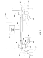
- FIG. 2 illustrates an exemplary apparatus or system 200 for applying coatings on an interior portion of a relatively high aspect ratio hollow substrate.
- a tubular substrate 202 may be mounted in between two insulators 204.
- the insulators 204 may be affixed to a multi-port fitting/coupling 206 formed of metal material which may provide fluid communication between the interior portion of the tubular object and a vacuum system 208 and a gas supply system 210.
- the vacuum system 208 and gas supply system 210 may be provided at one or both ends of the tubular substrate (as illustrated).
- the hollow substrate 202 may be positioned vertically (i.e.
- the vertical configuration may provide that carbon soot or other types of by-products, developed during the plasma formation, can fall more freely to the bottom of the hollow substrate and be more readily removed from the system.
- the vacuum system 208 may be provided in fluid communication with the interior portion of the tubular object 202.
- the vacuum system 208 may include, for example a momentum transfer pump 212 and a positive displacement, i.e., mechanical pump 214.
- Exemplary momentum transfer pumps may include diffusion pumps or turbomolecular pumps.
- One or more valves may be positioned between the vacuum system 208 and the tubular object. As presently illustrated the valves may include a throttle valve 216 and a gate valve 218. It should be appreciated that a number of other valves may be utilized as may be necessary by system requirements.
- gasses may be supplied to the tubular object 202 via a gas supply system 210, which may also be present at both ends of the hollow substrate, or at one end thereof, and which may include a gas inlet port 222. Gasses may therefore be fed from one or more storage devices 224 to the gas inlet port 222. One or more valves and/or regulators 226 may be supplied between the storage device 224 and the gas inlet port 222 aiding in the control of gas flow and pressure in the system 200.
- a pressure gauge 228 may be positioned on the multiport fitting/couplings 206 at one or both ends of the tubular substrate. The pressure gauge 228 may allow for the measurement of system pressure, which measurements may then be used to adjust or maintain the system pressure in a desired range or at a desired value. Accordingly, the control of pressure and/or gas flow may be provided manually or by an automated feed back system.
- a relatively high voltage pulsating DC power supply 230 may be connected to the hollow substrate 202 as illustrated which may then provide that the hollow substrate becomes biased with a negative voltage so that it may draw ions from the plasma to the substrate inner surface, wherein the ions may then simultaneously impinge on the inner surface to form a coating as explained more fully below.
- the voltage pulses may be less than or equal to about 10kV.
- the pulse frequency may be about 100 Hz to about 20 kHz, including all values and increments therein, at a pulse width from about 5 microseconds to about 40 microseconds, including all values and increments therein.
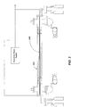
- the electrode 330 may be configured such that it may be connected to ground or be positively biased and configured to oppose the inner surface of the tubular substrate 302. This may then provide for relatively more uniform plasma formation within the hollow substrate as well as relatively more uniform ion coating of the hollow substrate inner surface. It may therefore be appreciated that FIG. 3 may include all of the illustrated features of FIG. 2 to regulate plasma formation wherein the electrode 330 may be specifically placed at about the center of the hollow substrate which may therefore be described as a center type electrode.
- the electrode 330 may itself be hollow with one or a plurality of spaced openings so that it may provide a pathway for the plasma precursor gases to travel down the length of such hollow electrode and be more uniformly distributed within a given hollow substrate.
- Such hollow electrode may itself have a diameter of up to about 0.50" (1.27 cm), including all values and ranges therein.
- the hollow electrode may have a diameter of about 0.25" (0.63 cm) to about 0.50" (1.27 cm).
- the hollow substrate in the event that the hollow substrate is positioned vertically, it may provide a more convenient configuration to ensure that the hollow electrode may span along the entire length of the substrate without contacts the inner surface and without the need for interim support.
- FIG. 4 An exemplary method of forming a wear and resistant coating on a hollow substrate is next illustrated in FIG. 4 .
- the interior surface of the hollow substrate may undergo sputter cleaning in the presence of an inert gas plasma or hydrogen. This may then substantially remove those contaminants (e.g. surface oxides and organic contaminants) from the inner surface which may then provide an improved ability to undergo ion coating.
- contaminants e.g. surface oxides and organic contaminants
- Reference to surface oxides may be understood herein as compounds containing oxygen, such as a metal oxide (e.g. aluminum oxide).
- the cleaning step may involve the introduction of an inert gas, such as argon, or a combination of argon ( Ar ) and a reactive gas such as hydrogen, to a pressure of about 0.5 to about 100 millitorr (mTorr) including all values and increments therein.
- an inert gas such as argon, or a combination of argon ( Ar ) and a reactive gas such as hydrogen
- a pulse frequency of from about 100 Hz to about 20 kHz may be applied, at a pulse width of about 5 microseconds to about 40 microseconds, to negatively bias the tube up to about 10 kV with respect to ground, for a period of up to about 60 minutes, including all values and increments therein.
- the argon ions may then be drawn to the inner surface to thereby provide sputter cleaning, wherein, e.g. about 75-100% of the surface oxides may be removed.
- the interior surface of the hollow substrate may also be optionally provided with a precursor bond coat which may be applied as an amorphous (non-crystalline) coupling layer as between the metallic surface and outer coating layers.
- a precursor bond coat which may be applied as an amorphous (non-crystalline) coupling layer as between the metallic surface and outer coating layers.
- Reference to coupling layer is reference to the feature that the precursor bond coat may improve the bonding strength as between the coating layer and the substrate surface.
- Suitable silicon containing precursors include, e.g. silane compounds, which may be understood as the silicon analogue of an alkane hydrocarbon, of the formula Si n H 2n+2 wherein n is an integer and may have a value of 1-10.
- a suitable silane compound may therefore include silicon tetrahydride (SiH 4 ).
- the silane compound may also include substituted aliphatic and/or aromatic functionality, e.g. trimethylsilane [SiH(CH 3 ) 3 ].
- the bond layer may be applied at pulse frequency of from about 100 Hz to about 20 kHz may be applied, at a pulse width of about 5 microseconds to about 40 microseconds, to negatively bias the tube up to about 10 kV with respect to ground, for a period of up to about 60 minutes, including all values and increments therein. For example, it has been found useful to negatively bias the tube at about 4 kV for a period of about 15 minutes
- the inner surface of the hollow substrate i.e. an inner surface without sputter cleaning and/or a precursor bond coating
- a plasma containing one or more inorganic or organic gaseous precursors which may be understood as any gas capable of forming an ion plasma, and which may then provide an inner surface wear-resistant coating of a desired thickness and hardness.
- the coatings may be applied on all or a portion of the inner surface of the hollow substrate, and may be relatively uniform in thickness, i.e. where such coating does not vary in thickness by more than about +/- 20% along the length of a given hollow substrate.
- the coatings may also exhibit a Vickers Hardness Number (Hv) of 500 or greater, including all values and increments in the range of 500 to 3000 (Hv).
- Hv Vickers Hardness Number
- the coatings herein may therefore be understood to include, but not be limited to, those coatings which are termed diamond like carbon (DLC) coatings which may be understood herein as coating that contain some amount of amorphous carbon.
- DLC diamond like carbon
- such coatings may include those which may exhibit a dry sliding (kinetic) coefficient of friction ( ⁇ k ) in the range of 0.01 to 0.2, including all values and increments therein.
- the coatings may exhibit an electrical resistivity in the range of about 10 x 10 6 to 10 x 10 14 ohm/cm, including all values and increments therein.
- the coatings may be applied at thicknesses in the range of about 0.1 to 15 microns, including all values and increments therein.
- the coatings also may exhibit a water contact angle ( CA ) in the range of 60° to 110°, including all values and increments therein.
- CA water contact angle
- the contact angle may be understood as the shape of a liquid water droplet as it rests on a solid surface.
- the contact angle is the measured angle between a tangent line at the drop boundary and the solid surface.
- Such contact angles indicate that the coating layers herein are relatively hydrophobic (i.e. they provide a relatively non-polar surface that does not interact well with polar molecules such as water).
- Exemplary precursor gasses suitable for formation of the above referenced coating on the interior surface of the hollow substrate may include hydrocarbon compounds (i.e. compounds containing carbon and hydrogen which may be provided as a gas) such as acetylene (C 2 H 2 ), ethylene (C 2 H 4 ) and/or methane (CH 4 ) etc., which may be used alone or in combination with precursor gases containing an inorganic element such as the silane compounds noted above (Si n H 2n+2 ), silicon carbide (SiC), silane compounds including substituted aliphatic and/or aromatic functionality hexamethyldisiloxane (HMDSO or (CH 3 ) 3 -Si-(CH 3 ) 3 ), trimethyl silane (3 MS or SiH(CH 3 ) 3 ), or other types of organic (carbon containing) gases such as perfluoropropane (CF 3 -CF 2 -CF 3 ) and/or hexafluoroethane (CF 3 -CF 3 ) and combinations
- exemplary precursor gases may include Cr-containing organic gases such as hexacarbonyl chromium (Cr(CO) 6 ) and/or Ti-containing gases such as Tetrakis titanium (Ti[N(CH 3 ) 2 ] 4 ).
- Cr-containing organic gases such as hexacarbonyl chromium (Cr(CO) 6
- Ti-containing gases such as Tetrakis titanium (Ti[N(CH 3 ) 2 ] 4 ).
- the coatings noted above may be formed on all of a portion of the interior surface of a hollow part such as hollow part 202 illustrated in FIG. 1 . More specifically, a vacuum may first be developed within the hollow part 202 to value of at or below about 10 -5 Torr. The above referenced gases may then be introduced at a flow rate of about 0.5 to 200 standard cubic centimeters per minute (sccm) while obtaining a pressure of about 0.5 to about 100 millitorr, including all values and increments therein. For example, the gases may be introduced at a flow of about 25-75 sccm to obtain a pressure of about 15-35 millitorr which is substantially uniform throughout the hollow substrates noted above.
- sccm standard cubic centimeters per minute
- the coating layer may then be applied at a pulse frequency of from about 100 Hz to about 20 kHz, a pulse width of about 5 microseconds to about 40 microseconds which may again negatively bias the tube up to about 10 kV with respect to ground, for a period of up to about 1500 minutes, including all values and increments therein.
- a second diamond like top coat may be formed over the first diamond like coating, wherein the second diamond like coating may be sourced from different precursor gases and may be applied at a different thickness, hardness or contact angle values as compared to the first diamond like coating.
- top coat may also be applied at thicknesses up to about 15.0 ⁇ m , it may be appreciated that a top coat may be more typically in the range of up to about 2.0 ⁇ m , including all values and increments therein. It is therefore specifically contemplated that more than two coating layers may be applied to the inner surface of a given hollow substrate wherein each layer may individually exhibit different physical properties [e.g. Vickers Hardness in the range of 500-3000, contact angles in the range of 60° to 110°, kinetic coefficient of frictions ( ⁇ k 0.01 - 0.20)] wherein any one of such properties may be varied between the layers.
- the coatings herein may be further characterized with respect to the presence of surface chemistry functionality via a technique such as X-ray photoelectron spectroscopy (XPS).
- XPS may be understood as a quantitative spectroscopic technique that may measure the empirical formula, chemical state and/or electronic state of the elements that exist at the surface of a sample.
- the XPS measurements may be performed by irradiating a material with a beam of X-rays while simultaneously measuring the kinetic energy (KE) and number of electrons that may be excited in the top 1 to 10 nm of the material being analyzed.
- KE kinetic energy
- the tubular substrate with internal surfaces coated as discussed above may be specifically incorporated into a pipeline system for the transportation of materials such as crude oil.
- a system is provided herein which incorporates at least a portion of pipeline having pipe sections that include plasma coatings on the interior surface.
- crude oil may contain various waxes and hydrates.
- the application of the coatings herein on the inside surfaces of piping that may be employed for crude oil transport may therefore provide a reduction in wax and/or hydrate build-up which may otherwise restrict oil flow.
- a number of coatings were initially produced on stainless steel and silicon wafer test coupons mounted on the inside surface of exemplary hollow substrate structures.
- the general deposition procedure generally included mounting the tubular structures inside of a vacuum chamber and evacuating the chamber to a pressure of 1.333 x 10 -3 Pa (1 x 10 -5 Torr) ; in the following the unit mTorr is used, and 1 mTorr corresponds to 0.1333 Pascal.
- the samples were cleaned using an inert gas (argon) plasma to remove residual hydrocarbon and/or metal oxide layers.
- argon inert gas
- Coatings were also applied to pipe (10 foot in length at about 4.0 inch diameter).
- the plasma coatings were applied in accordance with the above protocols and again, to evaluate coating efficiency, silicon coupons were positioned on the interior surface of the pipe to evaluate coating performance.
- Table 7 Sample Deposition on Hollow Substrate (Pipe) Deposition Sample No. Time (min) Pressure (mTorr) Inlet/Outlet Time (hr) Pressure (mTorr) Inlet/Outlet Gas SH-3 10 16.2/15.7 2.5 15/11 TMS SH-4 10 15/14 1.5 17.7/13 TMS Table 8. Thickness and Water Contact Angles for Si Coupons Sample No. Location Thickness ( ⁇ m) Contact Angles Ave. St. Dev.
Landscapes
- Chemical & Material Sciences (AREA)
- Engineering & Computer Science (AREA)
- Materials Engineering (AREA)
- General Chemical & Material Sciences (AREA)
- Chemical Kinetics & Catalysis (AREA)
- Mechanical Engineering (AREA)
- Metallurgy (AREA)
- Organic Chemistry (AREA)
- Plasma & Fusion (AREA)
- Physics & Mathematics (AREA)
- Inorganic Chemistry (AREA)
- Chemical Vapour Deposition (AREA)
- Physical Vapour Deposition (AREA)
Applications Claiming Priority (2)
| Application Number | Priority Date | Filing Date | Title |
|---|---|---|---|
| US11/752,787 US8029875B2 (en) | 2007-05-23 | 2007-05-23 | Plasma immersion ion processing for coating of hollow substrates |
| PCT/US2008/064344 WO2008147804A1 (en) | 2007-05-23 | 2008-05-21 | Plasma immersion ion processing for coating of hollow substrates |
Publications (3)
| Publication Number | Publication Date |
|---|---|
| EP2035596A1 EP2035596A1 (en) | 2009-03-18 |
| EP2035596A4 EP2035596A4 (en) | 2012-08-08 |
| EP2035596B1 true EP2035596B1 (en) | 2015-11-18 |
Family
ID=40072661
Family Applications (1)
| Application Number | Title | Priority Date | Filing Date |
|---|---|---|---|
| EP08756039.7A Active EP2035596B1 (en) | 2007-05-23 | 2008-05-21 | Plasma immersion ion processing for coating of hollow substrates |
Country Status (6)
| Country | Link |
|---|---|
| US (1) | US8029875B2 (pt) |
| EP (1) | EP2035596B1 (pt) |
| AU (1) | AU2008256944B2 (pt) |
| BR (1) | BRPI0803100B1 (pt) |
| MY (1) | MY154004A (pt) |
| WO (1) | WO2008147804A1 (pt) |
Families Citing this family (38)
| Publication number | Priority date | Publication date | Assignee | Title |
|---|---|---|---|---|
| US8029875B2 (en) | 2007-05-23 | 2011-10-04 | Southwest Research Institute | Plasma immersion ion processing for coating of hollow substrates |
| KR101514479B1 (ko) * | 2008-03-12 | 2015-04-22 | 알리투스 코포레이션 에스.에이. | 플라스마 시스템 |
| US9175381B2 (en) * | 2008-07-09 | 2015-11-03 | Southwest Research Institute | Processing tubular surfaces using double glow discharge |
| US8286715B2 (en) * | 2008-08-20 | 2012-10-16 | Exxonmobil Research And Engineering Company | Coated sleeved oil and gas well production devices |
| US8261841B2 (en) * | 2009-02-17 | 2012-09-11 | Exxonmobil Research And Engineering Company | Coated oil and gas well production devices |
| EP3222749A1 (en) | 2009-05-13 | 2017-09-27 | SiO2 Medical Products, Inc. | Outgassing method for inspecting a coated surface |
| US7985188B2 (en) | 2009-05-13 | 2011-07-26 | Cv Holdings Llc | Vessel, coating, inspection and processing apparatus |
| WO2013170052A1 (en) | 2012-05-09 | 2013-11-14 | Sio2 Medical Products, Inc. | Saccharide protective coating for pharmaceutical package |
| US9458536B2 (en) | 2009-07-02 | 2016-10-04 | Sio2 Medical Products, Inc. | PECVD coating methods for capped syringes, cartridges and other articles |
| US20110111132A1 (en) * | 2009-11-09 | 2011-05-12 | Electric Power Research Institute, Inc. | System and method for depositing coatings on inner surface of tubular structure |
| US8715789B2 (en) | 2009-12-18 | 2014-05-06 | Sub-One Technology, Inc. | Chemical vapor deposition for an interior of a hollow article with high aspect ratio |
| CN102859250B (zh) * | 2010-02-22 | 2016-04-13 | 埃克森美孚研究工程公司 | 经涂覆的带套筒油气井生产装置 |
| US11624115B2 (en) | 2010-05-12 | 2023-04-11 | Sio2 Medical Products, Inc. | Syringe with PECVD lubrication |
| US9878101B2 (en) | 2010-11-12 | 2018-01-30 | Sio2 Medical Products, Inc. | Cyclic olefin polymer vessels and vessel coating methods |
| US8753725B2 (en) * | 2011-03-11 | 2014-06-17 | Southwest Research Institute | Method for plasma immersion ion processing and depositing coatings in hollow substrates using a heated center electrode |
| US9272095B2 (en) | 2011-04-01 | 2016-03-01 | Sio2 Medical Products, Inc. | Vessels, contact surfaces, and coating and inspection apparatus and methods |
| US9340854B2 (en) | 2011-07-13 | 2016-05-17 | Baker Hughes Incorporated | Downhole motor with diamond-like carbon coating on stator and/or rotor and method of making said downhole motor |
| US11116695B2 (en) | 2011-11-11 | 2021-09-14 | Sio2 Medical Products, Inc. | Blood sample collection tube |
| WO2013071138A1 (en) | 2011-11-11 | 2013-05-16 | Sio2 Medical Products, Inc. | PASSIVATION, pH PROTECTIVE OR LUBRICITY COATING FOR PHARMACEUTICAL PACKAGE, COATING PROCESS AND APPARATUS |
| US20150297800A1 (en) | 2012-07-03 | 2015-10-22 | Sio2 Medical Products, Inc. | SiOx BARRIER FOR PHARMACEUTICAL PACKAGE AND COATING PROCESS |
| EP2914762B1 (en) | 2012-11-01 | 2020-05-13 | SiO2 Medical Products, Inc. | Coating inspection method |
| US9903782B2 (en) | 2012-11-16 | 2018-02-27 | Sio2 Medical Products, Inc. | Method and apparatus for detecting rapid barrier coating integrity characteristics |
| US9121540B2 (en) | 2012-11-21 | 2015-09-01 | Southwest Research Institute | Superhydrophobic compositions and coating process for the internal surface of tubular structures |
| US9764093B2 (en) | 2012-11-30 | 2017-09-19 | Sio2 Medical Products, Inc. | Controlling the uniformity of PECVD deposition |
| WO2014085348A2 (en) | 2012-11-30 | 2014-06-05 | Sio2 Medical Products, Inc. | Controlling the uniformity of pecvd deposition on medical syringes, cartridges, and the like |
| US20160015898A1 (en) | 2013-03-01 | 2016-01-21 | Sio2 Medical Products, Inc. | Plasma or cvd pre-treatment for lubricated pharmaceutical package, coating process and apparatus |
| JP6453841B2 (ja) | 2013-03-11 | 2019-01-16 | エスアイオーツー・メディカル・プロダクツ・インコーポレイテッド | 被覆包装 |
| US9937099B2 (en) | 2013-03-11 | 2018-04-10 | Sio2 Medical Products, Inc. | Trilayer coated pharmaceutical packaging with low oxygen transmission rate |
| US20160017490A1 (en) | 2013-03-15 | 2016-01-21 | Sio2 Medical Products, Inc. | Coating method |
| US9111734B2 (en) | 2013-10-31 | 2015-08-18 | General Electric Company | Systems and method of coating an interior surface of an object |
| EP3693493A1 (en) | 2014-03-28 | 2020-08-12 | SiO2 Medical Products, Inc. | Antistatic coatings for plastic vessels |
| US9523146B1 (en) | 2015-06-17 | 2016-12-20 | Southwest Research Institute | Ti—Si—C—N piston ring coatings |
| BR112018003051B1 (pt) | 2015-08-18 | 2022-12-06 | Sio2 Medical Products, Inc | Tubo de coleta de sangue submetido a vácuo |
| US12497698B2 (en) | 2016-05-06 | 2025-12-16 | Southwest Research Institute | Coatings formed from the deposition of plasma-activated adducts |
| US11371137B2 (en) | 2019-03-15 | 2022-06-28 | Halliburton Energy Services, Inc. | Depositing coatings on and within housings, apparatus, or tools |
| US11371145B2 (en) | 2019-03-15 | 2022-06-28 | Halliburton Energy Services, Inc. | Depositing coatings on and within a housing, apparatus, or tool using a coating system positioned therein |
| US11788187B2 (en) | 2020-08-27 | 2023-10-17 | Halliburton Energy Services, Inc. | Depositing coatings on and within housings, apparatus, or tools utilizing counter current flow of reactants |
| US11788189B2 (en) | 2020-08-27 | 2023-10-17 | Halliburton Energy Services, Inc. | Depositing coatings on and within housings, apparatus, or tools utilizing pressurized cells |
Citations (2)
| Publication number | Priority date | Publication date | Assignee | Title |
|---|---|---|---|---|
| JPS6326373A (ja) * | 1986-07-18 | 1988-02-03 | Kobe Steel Ltd | プラズマcvdによる管内面のコ−テイング方法 |
| US20060198965A1 (en) * | 2005-03-07 | 2006-09-07 | Tudhope Andrew W | Method and system for coating internal surfaces using reverse-flow cycling |
Family Cites Families (45)
| Publication number | Priority date | Publication date | Assignee | Title |
|---|---|---|---|---|
| DE3069702D1 (en) * | 1980-08-08 | 1985-01-10 | Battelle Development Corp | Apparatus for coating substrates by high-rate cathodic sputtering, as well as sputtering cathode for such apparatus |
| US4377773A (en) * | 1980-12-12 | 1983-03-22 | The United States Of America As Represented By The Department Of Energy | Negative ion source with hollow cathode discharge plasma |
| US4407712A (en) * | 1982-06-01 | 1983-10-04 | The United States Of America As Represented By The Secretary Of The Army | Hollow cathode discharge source of metal vapor |
| JPS592230A (ja) * | 1982-06-25 | 1984-01-07 | Toshiba Corp | フロッピー磁気ディスク記録媒体の製造方法 |
| US4731539A (en) * | 1983-05-26 | 1988-03-15 | Plaur Corporation | Method and apparatus for introducing normally solid material into substrate surfaces |
| US4520268A (en) * | 1983-05-26 | 1985-05-28 | Pauline Y. Lau | Method and apparatus for introducing normally solid materials into substrate surfaces |
| US4764394A (en) * | 1987-01-20 | 1988-08-16 | Wisconsin Alumni Research Foundation | Method and apparatus for plasma source ion implantation |
| US4795942A (en) * | 1987-04-27 | 1989-01-03 | Westinghouse Electric Corp. | Hollow cathode discharge device with front shield |
| JPH02205666A (ja) | 1989-02-01 | 1990-08-15 | Fujitsu Ltd | スパッタ膜の形成方法 |
| JPH02243766A (ja) | 1989-03-16 | 1990-09-27 | Fujitsu Ltd | 薄膜形成装置 |
| JPH0756781B2 (ja) * | 1992-04-24 | 1995-06-14 | 江東電気株式会社 | 中空陰極放電管 |
| US5593798A (en) * | 1992-07-06 | 1997-01-14 | The Regents Of The University Of California | Ion implantation of highly corrosive electrolyte battery components |
| US5249554A (en) * | 1993-01-08 | 1993-10-05 | Ford Motor Company | Powertrain component with adherent film having a graded composition |
| US5354381A (en) * | 1993-05-07 | 1994-10-11 | Varian Associates, Inc. | Plasma immersion ion implantation (PI3) apparatus |
| US5725573A (en) * | 1994-03-29 | 1998-03-10 | Southwest Research Institute | Medical implants made of metal alloys bearing cohesive diamond like carbon coatings |
| US6087025A (en) * | 1994-03-29 | 2000-07-11 | Southwest Research Institute | Application of diamond-like carbon coatings to cutting surfaces of metal cutting tools |
| US5605714A (en) * | 1994-03-29 | 1997-02-25 | Southwest Research Institute | Treatments to reduce thrombogeneticity in heart valves made from titanium and its alloys |
| US5458927A (en) * | 1995-03-08 | 1995-10-17 | General Motors Corporation | Process for the formation of wear- and scuff-resistant carbon coatings |
| US6410144B2 (en) * | 1995-03-08 | 2002-06-25 | Southwest Research Institute | Lubricious diamond-like carbon coatings |
| WO1999020086A2 (en) * | 1997-09-24 | 1999-04-22 | The Regents Of The University Of California | Process for forming adherent coatings using plasma processing |
| US6120660A (en) * | 1998-02-11 | 2000-09-19 | Silicon Genesis Corporation | Removable liner design for plasma immersion ion implantation |
| US6055928A (en) * | 1998-03-02 | 2000-05-02 | Ball Semiconductor, Inc. | Plasma immersion ion processor for fabricating semiconductor integrated circuits |
| SE516722C2 (sv) * | 1999-04-28 | 2002-02-19 | Hana Barankova | Förfarande och apparat för plasmabehandling av gas |
| US6874404B1 (en) * | 1999-05-28 | 2005-04-05 | Autoquip, Inc. | Compressed air flow rate controller |
| US8458879B2 (en) * | 2001-07-03 | 2013-06-11 | Advanced Bio Prosthetic Surfaces, Ltd., A Wholly Owned Subsidiary Of Palmaz Scientific, Inc. | Method of fabricating an implantable medical device |
| US6652763B1 (en) * | 2000-04-03 | 2003-11-25 | Hrl Laboratories, Llc | Method and apparatus for large-scale diamond polishing |
| US6497803B2 (en) * | 2000-05-31 | 2002-12-24 | Isoflux, Inc. | Unbalanced plasma generating apparatus having cylindrical symmetry |
| US6893907B2 (en) * | 2002-06-05 | 2005-05-17 | Applied Materials, Inc. | Fabrication of silicon-on-insulator structure using plasma immersion ion implantation |
| US7094670B2 (en) * | 2000-08-11 | 2006-08-22 | Applied Materials, Inc. | Plasma immersion ion implantation process |
| US20040025454A1 (en) * | 2000-09-05 | 2004-02-12 | Norman Burgess | Window frames |
| US7052736B2 (en) * | 2002-06-11 | 2006-05-30 | Southwest Research Institute | Method for depositing coatings on the interior surfaces of tubular structures |
| US6767436B2 (en) * | 2002-09-25 | 2004-07-27 | Hrl Laboratories, Llc | Method and apparatus of plasma-enhanced coaxial magnetron for sputter-coating interior surfaces |
| US6878404B2 (en) | 2003-02-06 | 2005-04-12 | Guardian Industries Corp. | Method of depositing DLC on substrate |
| US20050061251A1 (en) * | 2003-09-02 | 2005-03-24 | Ronghua Wei | Apparatus and method for metal plasma immersion ion implantation and metal plasma immersion ion deposition |
| US20050287307A1 (en) * | 2004-06-23 | 2005-12-29 | Varian Semiconductor Equipment Associates, Inc. | Etch and deposition control for plasma implantation |
| JP4548016B2 (ja) * | 2004-06-30 | 2010-09-22 | 日本電気株式会社 | トレイ内対象物の取出し装置 |
| US7300684B2 (en) * | 2004-07-15 | 2007-11-27 | Sub-One Technology, Inc. | Method and system for coating internal surfaces of prefabricated process piping in the field |
| US7520965B2 (en) * | 2004-10-12 | 2009-04-21 | Southwest Research Institute | Magnetron sputtering apparatus and method for depositing a coating using same |
| US7790003B2 (en) * | 2004-10-12 | 2010-09-07 | Southwest Research Institute | Method for magnetron sputter deposition |
| US20060076231A1 (en) * | 2004-10-12 | 2006-04-13 | Southwest Research Institute | Method for magnetron sputter deposition |
| US20060121704A1 (en) * | 2004-12-07 | 2006-06-08 | Varian Semiconductor Equipment Associates, Inc. | Plasma ion implantation system with axial electrostatic confinement |
| US7608151B2 (en) * | 2005-03-07 | 2009-10-27 | Sub-One Technology, Inc. | Method and system for coating sections of internal surfaces |
| DE102006032568A1 (de) * | 2006-07-12 | 2008-01-17 | Stein, Ralf | Verfahren zur plasmagestützten chemischen Gasphasenabscheidung an der Innenwand eines Hohlkörpers |
| US8029875B2 (en) | 2007-05-23 | 2011-10-04 | Southwest Research Institute | Plasma immersion ion processing for coating of hollow substrates |
| US9175381B2 (en) * | 2008-07-09 | 2015-11-03 | Southwest Research Institute | Processing tubular surfaces using double glow discharge |
-
2007
- 2007-05-23 US US11/752,787 patent/US8029875B2/en active Active
- 2007-05-23 MY MYPI20085018A patent/MY154004A/en unknown
-
2008
- 2008-05-21 WO PCT/US2008/064344 patent/WO2008147804A1/en not_active Ceased
- 2008-05-21 BR BRPI0803100-2A patent/BRPI0803100B1/pt active IP Right Grant
- 2008-05-21 EP EP08756039.7A patent/EP2035596B1/en active Active
- 2008-05-21 AU AU2008256944A patent/AU2008256944B2/en active Active
Patent Citations (2)
| Publication number | Priority date | Publication date | Assignee | Title |
|---|---|---|---|---|
| JPS6326373A (ja) * | 1986-07-18 | 1988-02-03 | Kobe Steel Ltd | プラズマcvdによる管内面のコ−テイング方法 |
| US20060198965A1 (en) * | 2005-03-07 | 2006-09-07 | Tudhope Andrew W | Method and system for coating internal surfaces using reverse-flow cycling |
Also Published As
| Publication number | Publication date |
|---|---|
| AU2008256944A1 (en) | 2008-12-04 |
| BRPI0803100B1 (pt) | 2019-04-24 |
| US20080292806A1 (en) | 2008-11-27 |
| WO2008147804A1 (en) | 2008-12-04 |
| AU2008256944B2 (en) | 2013-01-10 |
| US8029875B2 (en) | 2011-10-04 |
| MY154004A (en) | 2015-04-30 |
| EP2035596A1 (en) | 2009-03-18 |
| BRPI0803100A2 (pt) | 2011-08-30 |
| EP2035596A4 (en) | 2012-08-08 |
Similar Documents
| Publication | Publication Date | Title |
|---|---|---|
| EP2035596B1 (en) | Plasma immersion ion processing for coating of hollow substrates | |
| JP7520936B2 (ja) | 基材物品および装置の特性および性能を増強するためのコーティング | |
| US7052736B2 (en) | Method for depositing coatings on the interior surfaces of tubular structures | |
| US8394197B2 (en) | Corrosion-resistant internal coating method using a germanium-containing precursor and hollow cathode techniques | |
| EP2923137B1 (en) | Superhydrophobic coating process for the internal surface of tubular structures, tubular structures including such coating and system for forming such coating | |
| EP1034320B1 (en) | Method and apparatus for coating diamond-like carbon onto particles | |
| US7608151B2 (en) | Method and system for coating sections of internal surfaces | |
| US7718004B2 (en) | Gas-introducing system and plasma CVD apparatus | |
| US7629031B2 (en) | Plasma enhanced bonding for improving adhesion and corrosion resistance of deposited films | |
| Abbas et al. | A study of ta-C, aC: H and Si-a: C: H thin films on polymer substrates as a gas barrier | |
| US20120231177A1 (en) | Depositing Coatings In Long Hollow Substrates Using A Heated Center Electrode | |
| US20220122821A1 (en) | Methods of seasoning process chambers | |
| Detavernier et al. | Thermal versus plasma-enhanced ALD: growth kinetics and conformality | |
| Abd EL-Moaz et al. | RF-PLASMA PROTECTIVE COATING ON SILVER-COPPER ALLOYS USING HDMSO/O 2/AR PRECURSORS. | |
| SILVER | HDMSO/O2/AR PRECURSORS | |
| Verbrugge et al. | Design and experimentation of an inductive rf plasma process for high-speed carbon coating of silica optical fibres | |
| Miura et al. | Preparation of Carbon Related Thin Films Using Atmospheric Non-thermal Plasma Jet | |
| Jin et al. | Filling subquarter-micron trench structure with high-purity copper using plasma reactor with H atom source | |
| Hamerich et al. | Thin copper films deposited by low temperature plasma-enhanced metal organic chemical vapour deposition using copper-acetylacetonate | |
| Rebello | Design of a vacuum system for chemical vapor deposition | |
| WO2017192984A1 (en) | Coatings formed from the deposition of plasma-activated adducts | |
| HK1110907B (en) | Method and system for coating sections of internal surfaces |
Legal Events
| Date | Code | Title | Description |
|---|---|---|---|
| PUAI | Public reference made under article 153(3) epc to a published international application that has entered the european phase |
Free format text: ORIGINAL CODE: 0009012 |
|
| 17P | Request for examination filed |
Effective date: 20081215 |
|
| AK | Designated contracting states |
Kind code of ref document: A1 Designated state(s): AT BE BG CH CY CZ DE DK EE ES FI FR GB GR HR HU IE IS IT LI LT LU LV MC MT NL NO PL PT RO SE SI SK TR |
|
| AX | Request for extension of the european patent |
Extension state: AL BA MK RS |
|
| A4 | Supplementary search report drawn up and despatched |
Effective date: 20120705 |
|
| DAX | Request for extension of the european patent (deleted) | ||
| RIC1 | Information provided on ipc code assigned before grant |
Ipc: C23C 16/00 20060101AFI20120629BHEP Ipc: C23F 1/00 20060101ALI20120629BHEP |
|
| 17Q | First examination report despatched |
Effective date: 20130902 |
|
| REG | Reference to a national code |
Ref country code: DE Ref legal event code: R079 Ref document number: 602008041267 Country of ref document: DE Free format text: PREVIOUS MAIN CLASS: C23C0016000000 Ipc: C23C0016260000 |
|
| RIC1 | Information provided on ipc code assigned before grant |
Ipc: C23C 16/04 20060101ALI20150430BHEP Ipc: C23C 16/505 20060101ALI20150430BHEP Ipc: C23C 16/26 20060101AFI20150430BHEP Ipc: C23C 16/24 20060101ALI20150430BHEP Ipc: C23C 16/02 20060101ALI20150430BHEP |
|
| GRAP | Despatch of communication of intention to grant a patent |
Free format text: ORIGINAL CODE: EPIDOSNIGR1 |
|
| INTG | Intention to grant announced |
Effective date: 20150609 |
|
| GRAS | Grant fee paid |
Free format text: ORIGINAL CODE: EPIDOSNIGR3 |
|
| GRAA | (expected) grant |
Free format text: ORIGINAL CODE: 0009210 |
|
| AK | Designated contracting states |
Kind code of ref document: B1 Designated state(s): AT BE BG CH CY CZ DE DK EE ES FI FR GB GR HR HU IE IS IT LI LT LU LV MC MT NL NO PL PT RO SE SI SK TR |
|
| REG | Reference to a national code |
Ref country code: GB Ref legal event code: FG4D |
|
| REG | Reference to a national code |
Ref country code: CH Ref legal event code: EP |
|
| REG | Reference to a national code |
Ref country code: AT Ref legal event code: REF Ref document number: 761627 Country of ref document: AT Kind code of ref document: T Effective date: 20151215 |
|
| REG | Reference to a national code |
Ref country code: IE Ref legal event code: FG4D |
|
| REG | Reference to a national code |
Ref country code: DE Ref legal event code: R096 Ref document number: 602008041267 Country of ref document: DE |
|
| REG | Reference to a national code |
Ref country code: NL Ref legal event code: MP Effective date: 20160218 |
|
| REG | Reference to a national code |
Ref country code: LT Ref legal event code: MG4D |
|
| REG | Reference to a national code |
Ref country code: NO Ref legal event code: T2 Effective date: 20151118 |
|
| REG | Reference to a national code |
Ref country code: AT Ref legal event code: MK05 Ref document number: 761627 Country of ref document: AT Kind code of ref document: T Effective date: 20151118 |
|
| PG25 | Lapsed in a contracting state [announced via postgrant information from national office to epo] |
Ref country code: IS Free format text: LAPSE BECAUSE OF FAILURE TO SUBMIT A TRANSLATION OF THE DESCRIPTION OR TO PAY THE FEE WITHIN THE PRESCRIBED TIME-LIMIT Effective date: 20160318 Ref country code: NL Free format text: LAPSE BECAUSE OF FAILURE TO SUBMIT A TRANSLATION OF THE DESCRIPTION OR TO PAY THE FEE WITHIN THE PRESCRIBED TIME-LIMIT Effective date: 20151118 Ref country code: HR Free format text: LAPSE BECAUSE OF FAILURE TO SUBMIT A TRANSLATION OF THE DESCRIPTION OR TO PAY THE FEE WITHIN THE PRESCRIBED TIME-LIMIT Effective date: 20151118 Ref country code: ES Free format text: LAPSE BECAUSE OF FAILURE TO SUBMIT A TRANSLATION OF THE DESCRIPTION OR TO PAY THE FEE WITHIN THE PRESCRIBED TIME-LIMIT Effective date: 20151118 Ref country code: IT Free format text: LAPSE BECAUSE OF FAILURE TO SUBMIT A TRANSLATION OF THE DESCRIPTION OR TO PAY THE FEE WITHIN THE PRESCRIBED TIME-LIMIT Effective date: 20151118 Ref country code: LT Free format text: LAPSE BECAUSE OF FAILURE TO SUBMIT A TRANSLATION OF THE DESCRIPTION OR TO PAY THE FEE WITHIN THE PRESCRIBED TIME-LIMIT Effective date: 20151118 |
|
| PG25 | Lapsed in a contracting state [announced via postgrant information from national office to epo] |
Ref country code: AT Free format text: LAPSE BECAUSE OF FAILURE TO SUBMIT A TRANSLATION OF THE DESCRIPTION OR TO PAY THE FEE WITHIN THE PRESCRIBED TIME-LIMIT Effective date: 20151118 Ref country code: FI Free format text: LAPSE BECAUSE OF FAILURE TO SUBMIT A TRANSLATION OF THE DESCRIPTION OR TO PAY THE FEE WITHIN THE PRESCRIBED TIME-LIMIT Effective date: 20151118 Ref country code: LV Free format text: LAPSE BECAUSE OF FAILURE TO SUBMIT A TRANSLATION OF THE DESCRIPTION OR TO PAY THE FEE WITHIN THE PRESCRIBED TIME-LIMIT Effective date: 20151118 Ref country code: PT Free format text: LAPSE BECAUSE OF FAILURE TO SUBMIT A TRANSLATION OF THE DESCRIPTION OR TO PAY THE FEE WITHIN THE PRESCRIBED TIME-LIMIT Effective date: 20160318 Ref country code: PL Free format text: LAPSE BECAUSE OF FAILURE TO SUBMIT A TRANSLATION OF THE DESCRIPTION OR TO PAY THE FEE WITHIN THE PRESCRIBED TIME-LIMIT Effective date: 20151118 Ref country code: GR Free format text: LAPSE BECAUSE OF FAILURE TO SUBMIT A TRANSLATION OF THE DESCRIPTION OR TO PAY THE FEE WITHIN THE PRESCRIBED TIME-LIMIT Effective date: 20160219 Ref country code: SE Free format text: LAPSE BECAUSE OF FAILURE TO SUBMIT A TRANSLATION OF THE DESCRIPTION OR TO PAY THE FEE WITHIN THE PRESCRIBED TIME-LIMIT Effective date: 20151118 |
|
| PG25 | Lapsed in a contracting state [announced via postgrant information from national office to epo] |
Ref country code: CZ Free format text: LAPSE BECAUSE OF FAILURE TO SUBMIT A TRANSLATION OF THE DESCRIPTION OR TO PAY THE FEE WITHIN THE PRESCRIBED TIME-LIMIT Effective date: 20151118 |
|
| REG | Reference to a national code |
Ref country code: DE Ref legal event code: R097 Ref document number: 602008041267 Country of ref document: DE |
|
| PG25 | Lapsed in a contracting state [announced via postgrant information from national office to epo] |
Ref country code: SK Free format text: LAPSE BECAUSE OF FAILURE TO SUBMIT A TRANSLATION OF THE DESCRIPTION OR TO PAY THE FEE WITHIN THE PRESCRIBED TIME-LIMIT Effective date: 20151118 Ref country code: BE Free format text: LAPSE BECAUSE OF NON-PAYMENT OF DUE FEES Effective date: 20160531 Ref country code: DK Free format text: LAPSE BECAUSE OF FAILURE TO SUBMIT A TRANSLATION OF THE DESCRIPTION OR TO PAY THE FEE WITHIN THE PRESCRIBED TIME-LIMIT Effective date: 20151118 Ref country code: RO Free format text: LAPSE BECAUSE OF FAILURE TO SUBMIT A TRANSLATION OF THE DESCRIPTION OR TO PAY THE FEE WITHIN THE PRESCRIBED TIME-LIMIT Effective date: 20151118 Ref country code: EE Free format text: LAPSE BECAUSE OF FAILURE TO SUBMIT A TRANSLATION OF THE DESCRIPTION OR TO PAY THE FEE WITHIN THE PRESCRIBED TIME-LIMIT Effective date: 20151118 |
|
| PLBE | No opposition filed within time limit |
Free format text: ORIGINAL CODE: 0009261 |
|
| STAA | Information on the status of an ep patent application or granted ep patent |
Free format text: STATUS: NO OPPOSITION FILED WITHIN TIME LIMIT |
|
| 26N | No opposition filed |
Effective date: 20160819 |
|
| PG25 | Lapsed in a contracting state [announced via postgrant information from national office to epo] |
Ref country code: SI Free format text: LAPSE BECAUSE OF FAILURE TO SUBMIT A TRANSLATION OF THE DESCRIPTION OR TO PAY THE FEE WITHIN THE PRESCRIBED TIME-LIMIT Effective date: 20151118 |
|
| REG | Reference to a national code |
Ref country code: DE Ref legal event code: R119 Ref document number: 602008041267 Country of ref document: DE |
|
| PG25 | Lapsed in a contracting state [announced via postgrant information from national office to epo] |
Ref country code: BE Free format text: LAPSE BECAUSE OF FAILURE TO SUBMIT A TRANSLATION OF THE DESCRIPTION OR TO PAY THE FEE WITHIN THE PRESCRIBED TIME-LIMIT Effective date: 20151118 Ref country code: LU Free format text: LAPSE BECAUSE OF FAILURE TO SUBMIT A TRANSLATION OF THE DESCRIPTION OR TO PAY THE FEE WITHIN THE PRESCRIBED TIME-LIMIT Effective date: 20160521 |
|
| REG | Reference to a national code |
Ref country code: CH Ref legal event code: PL |
|
| PG25 | Lapsed in a contracting state [announced via postgrant information from national office to epo] |
Ref country code: LI Free format text: LAPSE BECAUSE OF NON-PAYMENT OF DUE FEES Effective date: 20160531 Ref country code: CH Free format text: LAPSE BECAUSE OF NON-PAYMENT OF DUE FEES Effective date: 20160531 |
|
| REG | Reference to a national code |
Ref country code: IE Ref legal event code: MM4A |
|
| REG | Reference to a national code |
Ref country code: FR Ref legal event code: ST Effective date: 20170131 |
|
| PG25 | Lapsed in a contracting state [announced via postgrant information from national office to epo] |
Ref country code: FR Free format text: LAPSE BECAUSE OF NON-PAYMENT OF DUE FEES Effective date: 20160531 Ref country code: DE Free format text: LAPSE BECAUSE OF NON-PAYMENT OF DUE FEES Effective date: 20161201 |
|
| PG25 | Lapsed in a contracting state [announced via postgrant information from national office to epo] |
Ref country code: IE Free format text: LAPSE BECAUSE OF NON-PAYMENT OF DUE FEES Effective date: 20160521 |
|
| PG25 | Lapsed in a contracting state [announced via postgrant information from national office to epo] |
Ref country code: HU Free format text: LAPSE BECAUSE OF FAILURE TO SUBMIT A TRANSLATION OF THE DESCRIPTION OR TO PAY THE FEE WITHIN THE PRESCRIBED TIME-LIMIT; INVALID AB INITIO Effective date: 20080521 Ref country code: CY Free format text: LAPSE BECAUSE OF FAILURE TO SUBMIT A TRANSLATION OF THE DESCRIPTION OR TO PAY THE FEE WITHIN THE PRESCRIBED TIME-LIMIT Effective date: 20151118 |
|
| PG25 | Lapsed in a contracting state [announced via postgrant information from national office to epo] |
Ref country code: MC Free format text: LAPSE BECAUSE OF FAILURE TO SUBMIT A TRANSLATION OF THE DESCRIPTION OR TO PAY THE FEE WITHIN THE PRESCRIBED TIME-LIMIT Effective date: 20151118 Ref country code: TR Free format text: LAPSE BECAUSE OF FAILURE TO SUBMIT A TRANSLATION OF THE DESCRIPTION OR TO PAY THE FEE WITHIN THE PRESCRIBED TIME-LIMIT Effective date: 20151118 Ref country code: MT Free format text: LAPSE BECAUSE OF NON-PAYMENT OF DUE FEES Effective date: 20160531 |
|
| PG25 | Lapsed in a contracting state [announced via postgrant information from national office to epo] |
Ref country code: BG Free format text: LAPSE BECAUSE OF FAILURE TO SUBMIT A TRANSLATION OF THE DESCRIPTION OR TO PAY THE FEE WITHIN THE PRESCRIBED TIME-LIMIT Effective date: 20151118 |
|
| P01 | Opt-out of the competence of the unified patent court (upc) registered |
Effective date: 20230601 |
|
| PGFP | Annual fee paid to national office [announced via postgrant information from national office to epo] |
Ref country code: GB Payment date: 20250527 Year of fee payment: 18 |
|
| PGFP | Annual fee paid to national office [announced via postgrant information from national office to epo] |
Ref country code: NO Payment date: 20250530 Year of fee payment: 18 |