EP2035285B1 - Karton mit tragegriff - Google Patents
Karton mit tragegriff Download PDFInfo
- Publication number
- EP2035285B1 EP2035285B1 EP07811914A EP07811914A EP2035285B1 EP 2035285 B1 EP2035285 B1 EP 2035285B1 EP 07811914 A EP07811914 A EP 07811914A EP 07811914 A EP07811914 A EP 07811914A EP 2035285 B1 EP2035285 B1 EP 2035285B1
- Authority
- EP
- European Patent Office
- Prior art keywords
- carton
- handle flap
- handle
- panel
- support structure
- Prior art date
- Legal status (The legal status is an assumption and is not a legal conclusion. Google has not performed a legal analysis and makes no representation as to the accuracy of the status listed.)
- Not-in-force
Links
- 239000000463 material Substances 0.000 description 6
- 238000010276 construction Methods 0.000 description 4
- 230000002787 reinforcement Effects 0.000 description 3
- 238000004026 adhesive bonding Methods 0.000 description 2
- 235000013361 beverage Nutrition 0.000 description 2
- 238000000034 method Methods 0.000 description 2
- 239000011087 paperboard Substances 0.000 description 2
- 230000015572 biosynthetic process Effects 0.000 description 1
- 239000003292 glue Substances 0.000 description 1
- 238000004519 manufacturing process Methods 0.000 description 1
- 238000004806 packaging method and process Methods 0.000 description 1
- 239000000843 powder Substances 0.000 description 1
- 238000005728 strengthening Methods 0.000 description 1
Images


Classifications
-
- B—PERFORMING OPERATIONS; TRANSPORTING
- B65—CONVEYING; PACKING; STORING; HANDLING THIN OR FILAMENTARY MATERIAL
- B65D—CONTAINERS FOR STORAGE OR TRANSPORT OF ARTICLES OR MATERIALS, e.g. BAGS, BARRELS, BOTTLES, BOXES, CANS, CARTONS, CRATES, DRUMS, JARS, TANKS, HOPPERS, FORWARDING CONTAINERS; ACCESSORIES, CLOSURES, OR FITTINGS THEREFOR; PACKAGING ELEMENTS; PACKAGES
- B65D5/00—Rigid or semi-rigid containers of polygonal cross-section, e.g. boxes, cartons or trays, formed by folding or erecting one or more blanks made of paper
- B65D5/42—Details of containers or of foldable or erectable container blanks
- B65D5/44—Integral, inserted or attached portions forming internal or external fittings
- B65D5/46—Handles
- B65D5/46072—Handles integral with the container
- B65D5/4608—Handgrip holes
Definitions
- the present invention relates to carrying handles for cartons and more specifically, but not exclusively to a strengthening and cushioning arrangement.
- WO2005/100174 discloses a carton arrangement wherein a series of handle flaps are provided which fold around the edge of the handle aperture thereby to reinforce the handle structure and to alleviate the discomfort that can be suffered by a user. This arrangement however provides only limited reinforcement and when cartons are heavy it is desirable to provide greater reinforcement and cushioning of the handle.
- EP0394730 discloses a package made from a blank having at least four wide and narrow side walls, connected via fold lines to form a tubular box, with lid and bottom closure tabs articulated thereon, all the wide and narrow side walls being of at least double layer construction by means of an inside frame the full inside volume of the package and its rigidity to be maintained in a powder tight design, a gripping opening is formed in an outer side wall by folding a gripping tab.
- a side carry carton is disclosed wherein complete inward folding of hand hole forming panel is prevented by an extension panel, which extension panel serves to reinforce the hand hole forming panel.
- the present invention serves to at least mitigate these and other problems of the prior art by providing an improved handle arrangement.
- the invention provides, a carton for containing articles, the carton comprising a handle for lifting the carton, said handle comprising a handle flap and a handle aperture each formed from one carton wall and a handle flap support structure disposed internally of said carton, the handle flap being foldable, internally of the carton, through the handle aperture thereby to facilitate lifting of the carton, the handle flap support structure resists the folding of said handle flap completely inwardly of the carton into overlapping relationship with said one carton wall and provides a resilient cushion for the carrying handle and the handle flap support structure comprises a panel, said panel including a connected part connected to an internal face of said handle flap, and a deformable part that is deformable such that when the handle flap is folded inwardly, the folded handle flap abuts the deformable part of said panel and fu rther inward folding of the handle flap is thereby restricted.
- the handle flap support structure is set-up automatically by virtue of folding the handle flap inwardly of the carton.
- said panel may include another connected part connected to a top panel of the carton and the deformable part of the panel is juxtaposed by each of the connected parts of the panel.
- At least a portion of the deformable part of said panel is deformable, upon moving the handle flap inwardly of the carton, to provide a strut that braces between the handle flap and said one carton wall. Even more preferably, at least a portion of the deformable part of said panel is deformable to provide a strut between a second wall of the carton and said one carton wall.
- the deformable part comprises a series of parallel fold lines.
- the fold lines predetermine the deformation of the handle flap support structure such that a tubular structure is set-up when the handle flap is folded inwardly of the carton.
- the tubular structure is formed from the deformable part and the one carton wall and is substantially triangular in cross section.
- the handle flap may optionally be foldable around the handle flap support structure such that the handle flap support structure provides a cushion.
- the deformable part of said panel substantially is co-extensive with said handle flap.
- the invention provides a flat pre-glued sleeve for forming a tubular carton, comprising a handle for lifting the carton, said handle comprising a handle flap and a handle aperture each formed from one carton wall and a handle flap support structure disposed internally of said carton, the handle flap being foldable, internally of the carton, through the handle aperture thereby to facilitate lifting of the carton, the handle flap support structure comprising a panel, said panel comprising a first part connected to an internal face of said handle flap, a second part that is deformable and a third part connected to a wall of the sleeve such that when the handle flap is folded inwardly, a strut between said handle flap and said one carton wall is formable and further inward folding of the handle flap is thereby restricted.
- the invention provides a blank for forming a carton having a carrying handle, the blank comprising a series of hinged panels for forming the carton walls, a handle flap struck from one of said carton walls and a handle flap support structure provided by and hinged to another of said carton walls, the handle flap support structure comprising a deformable panel and a connecting panel, the connecting panel for connecting the handle flap support structure to an inside face of said handle flap and said deformable panel for forming a tubular structure between the handle flap and said one carton wall.
- said handle flap support structure is hinged to an inner top wall of the carton and said one carton wall is hinged to an outer top panel and provides a side wall of the carton.
- the handle flap support structure is hinged to the inner top wall by a fold line aligned with a fold line between the outer top wall and said one carton wall.
- the handle flap support structure is hinged to the inner top wall by a fold line off set from a fold line between the outer top wall and said one carton wall.
- the deformable panel comprises at least a pair of fold lines to predetermine the deformation of said deformable panel when said tubular structure is formed.
- a hinged connection between the inner handle flap and deformable portion is aligned with a fold line connecting the handle flap to said one carton wall.
- a hinged connection between the inner handle flap and deformable portion is off set from a fold line connecting the handle flap to said one carton wall.
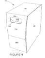
- FIG. 1 there is shown a blank 10 for forming an end-loading carton 100 (see Figure 4 ) made from paper board or similar foldable sheet material.
- the blank 10 comprises a series of main panels 20, 18, 16, 14 and 12 hinged one to the next along fold lines 22, 24, 26 and 28 respectively.
- a blank 10 is shown in Figure 1 ; the blank 10 may be formed from paperboard or other suitable sheet material that can be folded to construct a carton 100, which is shown in Figure 4 .
- the carton 100, of the present embodiment is used for packaging beverage containers such as bottles; other uses are of course envisaged.
- the blank 10 of Figure 1 comprises a series of main panels for forming the walls of the carton 100.
- the main panels include a top panel 20; first side panel 18, bottom panel 16, second side panel 14 and inner panel 12 hinged one to the next in series along fold lines 22, 24, 26 and 28 respectively.
- Each end of the carton 100 is at least partially closable by end flaps 70a, 68a, 66a and 64a, 70b, 68b, 66b and 64b which are hinged to the main panels along fold lines 32a, 34a, 36a, 38a, 32b, 34b, 36b and 38b, Use of end flaps for closing cartons is well known and will not be described in detail other than in relation to lop end flaps 70a and 70b wherein a handle flap 50a/50b is struck therefrom and hinged thereto.
- the handle flaps 50a/50b remain hinged to the respective top end flap 70a/70b along fold lines 30a/30b.
- blank 10 comprises an inner panel 12 hinged to each end of which, along fold line 40a, 40b is a deformable panel, collectively 52a/54a/56a and 52b/54b/56b.
- Each deformable panel 52a/54a/56a and 52b/54b/56b is defined by fold lines 55a & 57a and 55b & 57b.
- Fold lines 53a and 53b each connect an inner handle flap 62a, 62b to the respective deformable panel 52a/54a/56a or 52b/54b/56b.
- Hinged to the inner panel 12, along fold lines 67a, 67b are corner panels 60a, 60b, 60c and 60d, these corner panels 60a, 60b, 60c and 60d are entirely optional.
- the inner panel 12 and deformable panels 52a/54a/56a and 52b/54b/56b of the blank 10 are shown in enlarged form in Figure 1A .
- FIG. 1 are areas designated for gluing, these include G1 on inner panel 12, G2a, G2b on each of the inner handle flaps 62a, 62b and G3a, G3b, G3c and G3d on the optional corner panels 60a, 60b, 60c and 60d.
- the deformable panels 52a/54a/56a and 52b/54b/56b optionally are spaced from corner panels 60a, 60b, 60c and 60d by cut out portions 61a, 61b, 61c and 61d.
- a series of sequential folding and gluing operations are required, which preferably can be performed in a straight line machine, so that the carton 100 and/or blank 10 are not required to be rotated or inverted to complete the construction.
- the folding process is not limited to that described below and can be altered according to particular manufacturing requirements.
- Inner panel 12 is adhered to an inside face of top panel 20 by folding the blank 10 about fold line 26, so that the second side panel 14 and inner panel 12 overlay the bottom panel 16 and first side panel 18. Glue is then applied to areas G1, G2a/G2b, G3a/G3b/G3c and G3d. The top panel 20 is then folded about fold line 22 so that it overlays the inner panel 12 and becomes adhered thereto. Simultaneously, the corner panels 60a, 60b, 60c and 60d and inner handle flaps 62a, 62b are adhered to the top end flaps 70a and 70b respectively.
- Deformable panel 52a/54a/56a and 52ab54b/56b is disposed between the adhered portions of the inner panel 12 and inner handle flaps 62a, 62b and remains free of connection of the top panel 20 so that it may be deformed and erected into a handle flap support structure 80 as shown in Figures 2, 2A and 3 and described in detail bellow.
- the pre-glued carton blank in flat form is then erected into a tubular structure, the carton is loaded with articles from one or both ends and then the end flaps 70a. 68a, 66a and 64a, 70b, 68b, 66b and 64b are folded and glued to provide end closures of the carton 100 as illustrated in Figure 4 .
- the deformable panel 52a/54a/56a and 52ab54b/56b may be partially set-up, this is illustrated in Figure 2 .
- one or each handle flap and inner handle flap pair 50a/62a, 50b/62b is folded inwardly of the respective top end flap 70a, 70b though a handle aperture 15a, 15b which is thereby formed.
- the respective fold lines 55a, 57a or 55b, 57b cause a tubular handle flap support structure 80 to be set-up from portions 52a, 54a or 52, 54b of the respective deformable panel and a portion of the respective top end flap 70a or 70b, as shown in Figures 2A and 3 .
- the handle flap support structure is set-up, further inward folding of the or each handle flap and inner handle flap pair 50a/62a, 50b/62b becomes limited.
- the or each handle flap and inner handle flap pair 50a/62a, 50b/62b is prevented from being folded 180 degrees into alignment with the inside face of top end flap 70a/70b due to the handle flap support structure 80 providing a resilient cushion.
- FIG. 3 shows an internal view of the folded handle flap and inner handle flap pair 50a/62a and the handle flap support structure 80 providing the resilient cushion and resisting further inward folding of the handle flap and inner handle flap pair 50a/62a.
- the handle flap support structure 80 provides reinforcement of the handle structure and provides a structure which is more comfortable by which a user can grasp the carton 100 for lifting.
- the series of parallel lines 53a, 55a, 57a and 40a predetermine the shape and arrangement of the handle flap support structure 80 and determine the degree to which the inward folding of the or each handle flap and inner handle flap pair 50a/62a, 50b/62b is resisted.
- the series of parallel lines define a deformable portion which is juxtaposed and disposed between the inner handle flap 62a and the inner panel 12.
- the inner handle flap 62a and the inner panel 12 are each adhered to internal faces of the carton and thereby provide length to the carton 100 and to the handle structure.
- fold lines 40a & 40b are offset and not in alignment with the fold line 32a/32b between the top end flap 70a/70b and the top panel 20.
- the off-set arrangement of fold lines 40a/40b facilitates the partial automatic set-up of the handle flap support structure 80 when the blank 10 is set-up into a carton 100. This is illustrated in figures 2 and 2a .
- panel 56a/56b of the handle flap support structure 80 does not fold around the contour of the corner that is created between the top panel 20 and top-end flap 70a 70b, instead, due to the geometry of the deformable portion, panel 56a/56b is pushed outwardly of the internal corner and thus panel 54a/54b is also forced out of overlapping relationship with the top end flap 70a/70b as depicted in Figure 2A .
- the specific but exemplary arrangement depicted facilitates an optional initial set-up of the handle flap support structure 80 when the carton is first erected.
- the handle flap support structure 80 is automatically set-up by virtue of deploying the handle flap attached internally to the carton as it is set-up and formed.
- the handle flap support structure 80 may be formed from material not integral to the blank 10 from which the main body of the carton 100 is formed.
- a second embodiment of the invention is illustrated in Figures 5 to 6A .
- the second embodiment is similar to the first embodiment and therefore like reference numerals have been used to denote like features, albeit the reference numerals have been raised by a factor '100' to indicate that they relate to the second embodiment. Since the second embodiment is similar in many respects to the arrangement illustrated in respect of the first embodiment, only the differences are described in detail.
- fold lines 153a/153b are in alignment with fold lines 130a/130b and fold lines 140a/140b are in alignment with fold lines 132a/132b.
- the handle flap support structure 180 of the second embodiment is created utilizing the slack provided by the deformable portion 152a/154a/156a which is created upon folding the outer handle flap 150a inwardly of the top-end flap 170a.
- it is the excess material, or slack provided between fold lines 140a and 153a relative to the spacing between fold lines 132a and 130a that facilitates the formation of the 3-dimensional handle flap support structure 180, without depending upon the offset arrangement of the fold lines 30a and 53a and 32a and 56a, as in the first embodiment
- both the off-set fold arrangement and the excess material provided by the deformable portion contribute to the setting-up of the handle flap support structure 80.
- the second embodiment also differs from the first embodiment in that the deformable portion is separated, by means of cuts/slits 151a, 161b, 161c and 161d, from the adjacent glued portions 160 and 160 although in both embodiments the gaps 61a, 61b, 61c, 61d or slits 161a, 161b, 161c and 161d enable the deformable portion 52a/54a/56a and 152a/154a/156a to be erected into a 3D structure.
- the size and shape of the panels may be adjusted to accommodate articles of differing size or shape.
- the handle aperture and flap may be shaped in a different manner; the handle flap support structure may take various formals and indeed may not solely be formed from an inner panel integral with the remainder of the blank. Indeed a carton formed of more than a single part blank may incorporate the invention and the handle flap support structure may be formed from a separate piece of material.
- the handle flap support structure being automatically set-up upon deployment of the handle flap is an optional feature and it is envisaged that the handle flap support structure may be set-up internally of the carton in a number of ways, for example, during construction of the carton, preferably when the top-end flap 70a/70b is folded into position to close the end of the carton 100.
- the handle flap support structure 80 may take the form of a pre-folded cushion.
- hinged connection should not be construed as necessarily referring to a single fold line only; indeed it is envisaged that hinged connection can be formed from one or more of the following, a score line, a frangible line or a fold line without departing from the scope of the invention as defined by the claims.
Landscapes
- Engineering & Computer Science (AREA)
- Mechanical Engineering (AREA)
- Cartons (AREA)
- Steering Devices For Bicycles And Motorcycles (AREA)
- Details Of Rigid Or Semi-Rigid Containers (AREA)
Claims (15)
- Schachtel zum Aufnehmen von Artikeln, wobei die Schachtel einen Griff zum Anheben der Schachtel aufweist, wobei der Griff eine Griffklappe (50a, 150a) und eine Grifföffnung (15a) aufweist, die jeweils aus einer Schachtelwand (70a, 170a) ausgebildet sind, und eine Griffklappen-Stützstruktur, die im Inneren der Schachtel angeordnet ist, wobei die Griffklappe (50a, 150a) faltbar ist, in das Innere der Schachtel, und zwar durch die Grifföffnung, um so das Anheben der Schachtel zu ermöglichen, wobei die Griffklappen-Stützstruktur einem vollständigen Falten der Griffklappe in das Innere der Schachtel in überlappender Beziehung mit der einen Schachtelwand entgegenwirkt und eine nachgiebige Dämpfung für den Tragegriff vorsieht, wobei die Griffklappen-Stützstruktur eine Wandfläche aufweist, wobei die Wandfläche einen ersten Bereich (62a, 162a) aufweist, der mit einer inneren Fläche der Griffklappe verbunden ist,
dadurch gekennzeichnet, dass die Wandfläche ferner einen zweiten Bereich (52a/54a/56a, 152a/154a/156a) aufweist, der deformierbar ist, so dass, wenn die Griffklappe (50a, 150a) nach innen gefaltet wird, der erste Bereich der Wandfläche mit dem zweiten Bereich der Wandfläche in anstoßende Beziehung gelangt und das vollständige Falten der Griffklappe nach innen dadurch eingeschränkt ist. - Schachtel nach Anspruch 1, wobei die Griffklappen-Stützstruktur automatisch aufgrund des Faltens der Griffklappe in das Innere der Schachtel aufgestellt wird.
- Schachtel nach Anspruch 1 oder 2, wobei die Wandfläche ferner einen dritten Bereich (12, 112) aufweist, der mit einer Deckenwandfläche (20, 120) der Schachtel verbunden ist, und der zweite Bereich der Wandfläche, der deformierbar ist, in Juxtaposition sowohl mit dem ersten, als auch mit dem dritten Bereich der Wandfläche ist.
- Schachtel nach einem der Ansprüche 1 bis 3, wobei mindestens ein Abschnitt des zweiten Bereichs der Wandfläche deformierbar ist, und zwar bei Bewegen der Griffklappe in das Innere der Schachtel, um einen Holm (54a, 154a) vorzusehen, der sich zwischen der Griffklappe und der einen Schachtelwand (70a, 170a) abstützt.
- Schachtel nach einem der Ansprüche 1 bis 4, wobei mindestens ein Abschnitt des zweiten Bereichs der Wandfläche deformierbar ist, um einen Holm (56a) zwischen einer zweiten Wand der Schachtel und der einen Schachtelwand vorzusehen.
- Schachtel nach einem der Ansprüche 1 bis 5, wobei der zweite Bereich der Wandfläche eine Reihe von parallelen Faltlinien (53a, 55a, 57a, 153a, 155a, 157a) zum Festlegen der Deformation der Wandfläche aufweist, so dass eine röhrenförmige Struktur aufgestellt wird, wenn die Griffklappe in das Innere der Schachtel gefaltet wird, wobei die röhrenförmige Struktur im Wesentlichen dreieckförmig im Querschnitt ist.
- Schachtel nach einem der Ansprüche 1 bis 6, wobei die Griffklappe um die Griffklappen-Stützstruktur faltbar ist, so dass die Griffklappen-Stützstruktur eine Dämpfung aufweist.
- Schachtel nach einem der Ansprüche 5 bis 7, wobei der zweite Bereich der Wandfläche im Wesentlichen koextensiv mit der Griffklappe ist.
- Flache vorgeklebte Röhre zum Ausbilden einer röhrenförmigen Schachtel, die einen Griff zum Anheben der Schachtel aufweist, wobei der Griff eine Griffklappe (50a, 150a) und eine Grifföffnung (15a) aufweist, die jeweils aus einer Schachtelwand ausgebildet sind, und eine Griffklappen-Stützstruktur, die im Inneren der Schachtel angeordnet ist, wobei die Griffklappe faltbar ist, in das Innere der Schachtel, und zwar durch die Grifföffnung, um so das Anheben der Schachtel zu ermöglichen, wobei die Griffklappen-Stützstruktur eine Wandfläche aufweist, wobei die Wandfläche einen ersten Bereich (62a, 162a) aufweist, der mit einer inneren Fläche der Griffklappe verbunden ist, gekennzeichnet durch einen zweiten Bereich (52a/54a/56a, 152a/154a/156a), der deformierbar ist, und einen dritten Bereich (12, 112), der mit einer Wand der Röhre verbunden ist, so dass, wenn die Griffklappe nach innen gefaltet wird, ein Holm (54a, 154a) zwischen der Griffklappe und der einen Schachtelwand ausbildbar ist und ferner ein Falten der Griffklappe nach innen dadurch eingeschränkt ist.
- Verpackung, die eine Schachtel nach einem der Ansprüche 1 bis 8 aufweist und einen oder mehrere Artikel, wobei die Verpackung durch den Handgriff der Schachtel anhebbar ist.
- Zuschnitt zum Ausbilden einer Schachtel, die einen Tragegriff hat, wobei der Zuschnitt eine Reihe von gelenkig miteinander verbundenen Wandflächen zur Ausbildung der Schachtelwände aufweist, eine Griffklappe (50a, 150a), die aus einer der Schachtelwände (70a, 170a) ausgestanzt ist, und eine Griffklappen-Stützstruktur, die durch eine der Schachtelwände vorgesehen ist und mit einer anderen der Schachtelwände gelenkig verbunden ist, wobei die Griffklappen-Stützstruktur eine deformierbare Wandfläche (52a, 152a) aufweist und eine innere Griffklappe (62a, 162a), wobei die innere Griffklappe (62a, 162a) zum Verbinden der Griffklappen-Stützstruktur mit einer inneren Fläche der Griffklappe (50a, 150a) vorgesehen ist, und gekennzeichnet ist durch die deformierbare Wandfläche zum Ausbilden einer röhrenförmigen Struktur, zwischen der Griftklappe und der einen Schachtelwand.
- Zuschnitt nach Anspruch 11, wobei die Griffklappen-Stützstruktur gelenkig mit einer inneren Deckenwand (12, 112) der Schachtel verbunden ist, und die eine Schachtelwand einen Endverschluss der Schachtel vorsieht und gelenkig mit einer äußeren Deckenwandfläche (20, 120) der Schachtel verbunden ist.
- Zuschnitt nach Anspruch 12, wobei die Griffklappen-Stützstruktur gelenkig mit einer inneren Deckenwand (112) verbunden ist, durch eine Faltlinie (140a), die ausgerichtet ist mit einer Faltlinie (132a) zwischen der äußeren Deckenwand (120) und der einen Schachtelwand (170a) oder wobei die Griffklappen-Stützstruktur gelenkig mit der inneren Deckenwand (12) verbunden ist, durch eine Faltlinie (40a), die versetzt von einer Faltlinie (32a) zwischen der äußeren Deckenwand (20) und der einen Schachtelwand (70a) angeordnet ist.
- Zuschnitt nach einem der Ansprüche 11 bis 13, wobei die deformierbare Wandfläche mindestens ein Paar von Faltlinien (53a, 55a, 57a, 153a, 155a, 157a) aufweist, um die Deformation der deformierbaren Wandfläche festzulegen, wenn die röhrenförmige Struktur ausgebildet wird.
- Zuschnitt nach einem der Ansprüche 11 bis 14, wobei eine gelenkige Verbindung (153a) zwischen der inneren Griffklappe und dem deformierbaren Abschnitt mit einer Faltlinie (130a) ausgerichtet ist, welche die Griffklappe mit der einen Schachtelwand verbindet, oder wobei eine gelenkige Verbindung (53a) zwischen der inneren Griffklappe und dem deformierbaren Abschnitt versetzt von der Faltlinie (30a) ist, welche die Griffklappe mit der einen Schachtelwand verbindet.
Priority Applications (1)
| Application Number | Priority Date | Filing Date | Title |
|---|---|---|---|
| PL07811914T PL2035285T3 (pl) | 2006-05-19 | 2007-05-21 | Karton z uchwytem nośnym |
Applications Claiming Priority (2)
| Application Number | Priority Date | Filing Date | Title |
|---|---|---|---|
| GB0610005A GB2438190A (en) | 2006-05-19 | 2006-05-19 | Carrying handle for carton |
| PCT/US2007/069380 WO2007137231A2 (en) | 2006-05-19 | 2007-05-21 | Carton with carrying handle |
Publications (3)
| Publication Number | Publication Date |
|---|---|
| EP2035285A2 EP2035285A2 (de) | 2009-03-18 |
| EP2035285B1 true EP2035285B1 (de) | 2010-11-17 |
| EP2035285B9 EP2035285B9 (de) | 2011-02-16 |
Family
ID=36660510
Family Applications (1)
| Application Number | Title | Priority Date | Filing Date |
|---|---|---|---|
| EP07811914A Not-in-force EP2035285B9 (de) | 2006-05-19 | 2007-05-21 | Karton mit tragegriff |
Country Status (7)
| Country | Link |
|---|---|
| EP (1) | EP2035285B9 (de) |
| AT (1) | ATE488438T1 (de) |
| DE (1) | DE602007010627D1 (de) |
| ES (1) | ES2356993T3 (de) |
| GB (1) | GB2438190A (de) |
| PL (1) | PL2035285T3 (de) |
| WO (1) | WO2007137231A2 (de) |
Families Citing this family (1)
| Publication number | Priority date | Publication date | Assignee | Title |
|---|---|---|---|---|
| CN104981408A (zh) | 2012-10-24 | 2015-10-14 | 米德韦斯特瓦科包装系统有限责任公司 | 具有条带把手的包装物 |
Family Cites Families (6)
| Publication number | Priority date | Publication date | Assignee | Title |
|---|---|---|---|---|
| DE2547443C3 (de) * | 1975-10-23 | 1984-06-07 | Licentia Patent-Verwaltungs-Gmbh, 6000 Frankfurt | Karton zum Verpacken von schweren Geräten, insbesondere von Farbfernsehempfängern |
| US4058250A (en) * | 1976-05-04 | 1977-11-15 | Domtar Limited | Reinforced side carry carton |
| US4058280A (en) | 1976-07-21 | 1977-11-15 | Timothy Clancy | Table rail |
| DE3913549A1 (de) * | 1989-04-25 | 1990-10-31 | Henkel Kgaa | Verpackung aus einem faltzuschnitt mit breit- und schmalseitenwaenden und mit in eine seitenwand integrierter griffoeffnung |
| US5803347A (en) * | 1995-06-26 | 1998-09-08 | Sainz; Raymond R. | Protective device for use with containers having handhold openings |
| GB0408052D0 (en) | 2004-04-08 | 2004-05-12 | Meadwestvaco Packaging Systems | Carton and carton blank with reinforced handle structure |
-
2006
- 2006-05-19 GB GB0610005A patent/GB2438190A/en not_active Withdrawn
-
2007
- 2007-05-21 EP EP07811914A patent/EP2035285B9/de not_active Not-in-force
- 2007-05-21 WO PCT/US2007/069380 patent/WO2007137231A2/en not_active Ceased
- 2007-05-21 AT AT07811914T patent/ATE488438T1/de not_active IP Right Cessation
- 2007-05-21 DE DE602007010627T patent/DE602007010627D1/de active Active
- 2007-05-21 ES ES07811914T patent/ES2356993T3/es active Active
- 2007-05-21 PL PL07811914T patent/PL2035285T3/pl unknown
Also Published As
| Publication number | Publication date |
|---|---|
| ATE488438T1 (de) | 2010-12-15 |
| PL2035285T3 (pl) | 2011-05-31 |
| EP2035285A2 (de) | 2009-03-18 |
| EP2035285B9 (de) | 2011-02-16 |
| GB0610005D0 (en) | 2006-06-28 |
| GB2438190A (en) | 2007-11-21 |
| WO2007137231A2 (en) | 2007-11-29 |
| WO2007137231A3 (en) | 2008-01-10 |
| DE602007010627D1 (de) | 2010-12-30 |
| ES2356993T3 (es) | 2011-04-15 |
Similar Documents
| Publication | Publication Date | Title |
|---|---|---|
| US7000824B2 (en) | Carton and carton blank therefor | |
| US7427011B2 (en) | Carton and insert and blank for forming the same | |
| EP1611025B1 (de) | Handgriff und verstärkung des oberteiles eines handgriffes für eine kartonfaltschachtel | |
| CA2987725C (en) | Carton and carton blank | |
| US5911359A (en) | Flip-top carton with integral partial collar | |
| EP2911941B1 (de) | Verpackung mit einem riemengriff, ein riemengriff und ein zuschnitt für eine verpackung mit einem riemangriff | |
| EP1853483B1 (de) | Karton mit seitenfaltengriff | |
| US2824684A (en) | Carton | |
| AU2017336687B2 (en) | Carton and carton blank | |
| US8523047B2 (en) | Handle structure | |
| EP3645414A1 (de) | Karton und zuschnitt dafür | |
| US3036754A (en) | Cushioned end closure device for cartons | |
| EP1218247B1 (de) | Karton und kartonzuschnitt | |
| EP2035285B1 (de) | Karton mit tragegriff | |
| EP1456088B1 (de) | Karton und kartonzuschnitt | |
| ZA200301855B (en) | Carton and insert and blank for forming the same. | |
| JP3225123B2 (ja) | 缶カートン | |
| WO2024238100A1 (en) | Article carrier and blank therefor | |
| US8434672B2 (en) | Carton with carrying handle and blank therefor | |
| HK1075876B (en) | Carton and carton blank |
Legal Events
| Date | Code | Title | Description |
|---|---|---|---|
| PUAI | Public reference made under article 153(3) epc to a published international application that has entered the european phase |
Free format text: ORIGINAL CODE: 0009012 |
|
| 17P | Request for examination filed |
Effective date: 20080908 |
|
| AK | Designated contracting states |
Kind code of ref document: A2 Designated state(s): AT BE BG CH CY CZ DE DK EE ES FI FR GB GR HU IE IS IT LI LT LU LV MC MT NL PL PT RO SE SI SK TR |
|
| AX | Request for extension of the european patent |
Extension state: AL BA HR MK RS |
|
| DAX | Request for extension of the european patent (deleted) | ||
| GRAP | Despatch of communication of intention to grant a patent |
Free format text: ORIGINAL CODE: EPIDOSNIGR1 |
|
| RAP1 | Party data changed (applicant data changed or rights of an application transferred) |
Owner name: MEADWESTVACO PACKAGING SYSTEMS LLC |
|
| GRAS | Grant fee paid |
Free format text: ORIGINAL CODE: EPIDOSNIGR3 |
|
| GRAA | (expected) grant |
Free format text: ORIGINAL CODE: 0009210 |
|
| AK | Designated contracting states |
Kind code of ref document: B1 Designated state(s): AT BE BG CH CY CZ DE DK EE ES FI FR GB GR HU IE IS IT LI LT LU LV MC MT NL PL PT RO SE SI SK TR |
|
| REG | Reference to a national code |
Ref country code: GB Ref legal event code: FG4D |
|
| REG | Reference to a national code |
Ref country code: CH Ref legal event code: EP |
|
| RAP2 | Party data changed (patent owner data changed or rights of a patent transferred) |
Owner name: MEADWESTVACO PACKAGING SYSTEMS, LLC |
|
| REG | Reference to a national code |
Ref country code: IE Ref legal event code: FG4D |
|
| REF | Corresponds to: |
Ref document number: 602007010627 Country of ref document: DE Date of ref document: 20101230 Kind code of ref document: P |
|
| REG | Reference to a national code |
Ref country code: NL Ref legal event code: T3 |
|
| REG | Reference to a national code |
Ref country code: ES Ref legal event code: FG2A Ref document number: 2356993 Country of ref document: ES Kind code of ref document: T3 Effective date: 20110415 |
|
| LTIE | Lt: invalidation of european patent or patent extension |
Effective date: 20101117 |
|
| PG25 | Lapsed in a contracting state [announced via postgrant information from national office to epo] |
Ref country code: LT Free format text: LAPSE BECAUSE OF FAILURE TO SUBMIT A TRANSLATION OF THE DESCRIPTION OR TO PAY THE FEE WITHIN THE PRESCRIBED TIME-LIMIT Effective date: 20101117 |
|
| PG25 | Lapsed in a contracting state [announced via postgrant information from national office to epo] |
Ref country code: SE Free format text: LAPSE BECAUSE OF FAILURE TO SUBMIT A TRANSLATION OF THE DESCRIPTION OR TO PAY THE FEE WITHIN THE PRESCRIBED TIME-LIMIT Effective date: 20101117 Ref country code: FI Free format text: LAPSE BECAUSE OF FAILURE TO SUBMIT A TRANSLATION OF THE DESCRIPTION OR TO PAY THE FEE WITHIN THE PRESCRIBED TIME-LIMIT Effective date: 20101117 Ref country code: IS Free format text: LAPSE BECAUSE OF FAILURE TO SUBMIT A TRANSLATION OF THE DESCRIPTION OR TO PAY THE FEE WITHIN THE PRESCRIBED TIME-LIMIT Effective date: 20110317 Ref country code: AT Free format text: LAPSE BECAUSE OF FAILURE TO SUBMIT A TRANSLATION OF THE DESCRIPTION OR TO PAY THE FEE WITHIN THE PRESCRIBED TIME-LIMIT Effective date: 20101117 Ref country code: SI Free format text: LAPSE BECAUSE OF FAILURE TO SUBMIT A TRANSLATION OF THE DESCRIPTION OR TO PAY THE FEE WITHIN THE PRESCRIBED TIME-LIMIT Effective date: 20101117 Ref country code: BG Free format text: LAPSE BECAUSE OF FAILURE TO SUBMIT A TRANSLATION OF THE DESCRIPTION OR TO PAY THE FEE WITHIN THE PRESCRIBED TIME-LIMIT Effective date: 20110217 Ref country code: CY Free format text: LAPSE BECAUSE OF FAILURE TO SUBMIT A TRANSLATION OF THE DESCRIPTION OR TO PAY THE FEE WITHIN THE PRESCRIBED TIME-LIMIT Effective date: 20101117 Ref country code: PT Free format text: LAPSE BECAUSE OF FAILURE TO SUBMIT A TRANSLATION OF THE DESCRIPTION OR TO PAY THE FEE WITHIN THE PRESCRIBED TIME-LIMIT Effective date: 20110317 Ref country code: LV Free format text: LAPSE BECAUSE OF FAILURE TO SUBMIT A TRANSLATION OF THE DESCRIPTION OR TO PAY THE FEE WITHIN THE PRESCRIBED TIME-LIMIT Effective date: 20101117 |
|
| REG | Reference to a national code |
Ref country code: PL Ref legal event code: T3 |
|
| PG25 | Lapsed in a contracting state [announced via postgrant information from national office to epo] |
Ref country code: GR Free format text: LAPSE BECAUSE OF FAILURE TO SUBMIT A TRANSLATION OF THE DESCRIPTION OR TO PAY THE FEE WITHIN THE PRESCRIBED TIME-LIMIT Effective date: 20110218 |
|
| PG25 | Lapsed in a contracting state [announced via postgrant information from national office to epo] |
Ref country code: CZ Free format text: LAPSE BECAUSE OF FAILURE TO SUBMIT A TRANSLATION OF THE DESCRIPTION OR TO PAY THE FEE WITHIN THE PRESCRIBED TIME-LIMIT Effective date: 20101117 Ref country code: EE Free format text: LAPSE BECAUSE OF FAILURE TO SUBMIT A TRANSLATION OF THE DESCRIPTION OR TO PAY THE FEE WITHIN THE PRESCRIBED TIME-LIMIT Effective date: 20101117 |
|
| PG25 | Lapsed in a contracting state [announced via postgrant information from national office to epo] |
Ref country code: RO Free format text: LAPSE BECAUSE OF FAILURE TO SUBMIT A TRANSLATION OF THE DESCRIPTION OR TO PAY THE FEE WITHIN THE PRESCRIBED TIME-LIMIT Effective date: 20101117 Ref country code: DK Free format text: LAPSE BECAUSE OF FAILURE TO SUBMIT A TRANSLATION OF THE DESCRIPTION OR TO PAY THE FEE WITHIN THE PRESCRIBED TIME-LIMIT Effective date: 20101117 Ref country code: SK Free format text: LAPSE BECAUSE OF FAILURE TO SUBMIT A TRANSLATION OF THE DESCRIPTION OR TO PAY THE FEE WITHIN THE PRESCRIBED TIME-LIMIT Effective date: 20101117 |
|
| PLBE | No opposition filed within time limit |
Free format text: ORIGINAL CODE: 0009261 |
|
| STAA | Information on the status of an ep patent application or granted ep patent |
Free format text: STATUS: NO OPPOSITION FILED WITHIN TIME LIMIT |
|
| 26N | No opposition filed |
Effective date: 20110818 |
|
| REG | Reference to a national code |
Ref country code: DE Ref legal event code: R097 Ref document number: 602007010627 Country of ref document: DE Effective date: 20110818 |
|
| PG25 | Lapsed in a contracting state [announced via postgrant information from national office to epo] |
Ref country code: MT Free format text: LAPSE BECAUSE OF FAILURE TO SUBMIT A TRANSLATION OF THE DESCRIPTION OR TO PAY THE FEE WITHIN THE PRESCRIBED TIME-LIMIT Effective date: 20101117 Ref country code: MC Free format text: LAPSE BECAUSE OF NON-PAYMENT OF DUE FEES Effective date: 20110531 |
|
| REG | Reference to a national code |
Ref country code: CH Ref legal event code: PL |
|
| PG25 | Lapsed in a contracting state [announced via postgrant information from national office to epo] |
Ref country code: CH Free format text: LAPSE BECAUSE OF NON-PAYMENT OF DUE FEES Effective date: 20110531 Ref country code: LI Free format text: LAPSE BECAUSE OF NON-PAYMENT OF DUE FEES Effective date: 20110531 |
|
| PG25 | Lapsed in a contracting state [announced via postgrant information from national office to epo] |
Ref country code: IT Free format text: LAPSE BECAUSE OF NON-PAYMENT OF DUE FEES Effective date: 20110521 |
|
| REG | Reference to a national code |
Ref country code: IE Ref legal event code: MM4A |
|
| PG25 | Lapsed in a contracting state [announced via postgrant information from national office to epo] |
Ref country code: IE Free format text: LAPSE BECAUSE OF NON-PAYMENT OF DUE FEES Effective date: 20110521 |
|
| REG | Reference to a national code |
Ref country code: ES Ref legal event code: FD2A Effective date: 20120717 |
|
| PG25 | Lapsed in a contracting state [announced via postgrant information from national office to epo] |
Ref country code: ES Free format text: LAPSE BECAUSE OF NON-PAYMENT OF DUE FEES Effective date: 20110522 |
|
| PGFP | Annual fee paid to national office [announced via postgrant information from national office to epo] |
Ref country code: NL Payment date: 20120530 Year of fee payment: 6 Ref country code: DE Payment date: 20120529 Year of fee payment: 6 |
|
| PGFP | Annual fee paid to national office [announced via postgrant information from national office to epo] |
Ref country code: GB Payment date: 20120525 Year of fee payment: 6 Ref country code: BE Payment date: 20120529 Year of fee payment: 6 Ref country code: FR Payment date: 20120607 Year of fee payment: 6 |
|
| PG25 | Lapsed in a contracting state [announced via postgrant information from national office to epo] |
Ref country code: PL Free format text: LAPSE BECAUSE OF NON-PAYMENT OF DUE FEES Effective date: 20110521 |
|
| REG | Reference to a national code |
Ref country code: PL Ref legal event code: LAPE |
|
| PG25 | Lapsed in a contracting state [announced via postgrant information from national office to epo] |
Ref country code: LU Free format text: LAPSE BECAUSE OF NON-PAYMENT OF DUE FEES Effective date: 20110521 |
|
| PG25 | Lapsed in a contracting state [announced via postgrant information from national office to epo] |
Ref country code: TR Free format text: LAPSE BECAUSE OF FAILURE TO SUBMIT A TRANSLATION OF THE DESCRIPTION OR TO PAY THE FEE WITHIN THE PRESCRIBED TIME-LIMIT Effective date: 20101117 |
|
| PG25 | Lapsed in a contracting state [announced via postgrant information from national office to epo] |
Ref country code: HU Free format text: LAPSE BECAUSE OF FAILURE TO SUBMIT A TRANSLATION OF THE DESCRIPTION OR TO PAY THE FEE WITHIN THE PRESCRIBED TIME-LIMIT Effective date: 20101117 |
|
| BERE | Be: lapsed |
Owner name: MEADWESTVACO PACKAGING SYSTEMS LLC Effective date: 20130531 |
|
| REG | Reference to a national code |
Ref country code: NL Ref legal event code: V1 Effective date: 20131201 |
|
| GBPC | Gb: european patent ceased through non-payment of renewal fee |
Effective date: 20130521 |
|
| PG25 | Lapsed in a contracting state [announced via postgrant information from national office to epo] |
Ref country code: DE Free format text: LAPSE BECAUSE OF NON-PAYMENT OF DUE FEES Effective date: 20131203 |
|
| PG25 | Lapsed in a contracting state [announced via postgrant information from national office to epo] |
Ref country code: BE Free format text: LAPSE BECAUSE OF NON-PAYMENT OF DUE FEES Effective date: 20130531 Ref country code: NL Free format text: LAPSE BECAUSE OF NON-PAYMENT OF DUE FEES Effective date: 20131201 |
|
| REG | Reference to a national code |
Ref country code: FR Ref legal event code: ST Effective date: 20140131 |
|
| REG | Reference to a national code |
Ref country code: DE Ref legal event code: R119 Ref document number: 602007010627 Country of ref document: DE Effective date: 20131203 |
|
| PG25 | Lapsed in a contracting state [announced via postgrant information from national office to epo] |
Ref country code: GB Free format text: LAPSE BECAUSE OF NON-PAYMENT OF DUE FEES Effective date: 20130521 |
|
| PG25 | Lapsed in a contracting state [announced via postgrant information from national office to epo] |
Ref country code: FR Free format text: LAPSE BECAUSE OF NON-PAYMENT OF DUE FEES Effective date: 20130531 |