EP2035189B1 - Schleifartikel und verfahren zu seiner herstellung und verwendung - Google Patents
Schleifartikel und verfahren zu seiner herstellung und verwendung Download PDFInfo
- Publication number
- EP2035189B1 EP2035189B1 EP07811982A EP07811982A EP2035189B1 EP 2035189 B1 EP2035189 B1 EP 2035189B1 EP 07811982 A EP07811982 A EP 07811982A EP 07811982 A EP07811982 A EP 07811982A EP 2035189 B1 EP2035189 B1 EP 2035189B1
- Authority
- EP
- European Patent Office
- Prior art keywords
- filter medium
- abrasive
- attachment interface
- interface member
- abrasive article
- Prior art date
- Legal status (The legal status is an assumption and is not a legal conclusion. Google has not performed a legal analysis and makes no representation as to the accuracy of the status listed.)
- Not-in-force
Links
Images


Classifications
-
- B—PERFORMING OPERATIONS; TRANSPORTING
- B24—GRINDING; POLISHING
- B24D—TOOLS FOR GRINDING, BUFFING OR SHARPENING
- B24D11/00—Constructional features of flexible abrasive materials; Special features in the manufacture of such materials
- B24D11/02—Backings, e.g. foils, webs, mesh fabrics
-
- B—PERFORMING OPERATIONS; TRANSPORTING
- B24—GRINDING; POLISHING
- B24B—MACHINES, DEVICES, OR PROCESSES FOR GRINDING OR POLISHING; DRESSING OR CONDITIONING OF ABRADING SURFACES; FEEDING OF GRINDING, POLISHING, OR LAPPING AGENTS
- B24B23/00—Portable grinding machines, e.g. hand-guided; Accessories therefor
- B24B23/005—Auxiliary devices used in connection with portable grinding machines, e.g. holders
Definitions
- Abrasive articles are used in industry for abrading, grinding, and polishing applications. They may be obtained in a variety of converted forms, such as belts, discs, sheets, and the like, in many different sizes.
- a back-up pad is used to mount or attach the abrasive article to the abrading tool.
- One type of back-up pad has dust collection holes connected by a series of grooves. The dust collection holes are typically connected to a vacuum source to help control swarf build-up on the abrading surface of the abrasive article. Removing the swarf, dust, and debris from the abrading surface as e.g. disclosed in document US-A1-2003/0003856 is known to improve the performance of the abrasive article.
- Some abrasive tools have integral vacuum systems with dust collection means.
- the extracting and holding capabilities of these abrasive tools have been limited, in part, due to the suction requirements of current abrasive disks that their related back-up pads require.
- swarf is collected in a complex dust collection system through a hose connected to the abrasive tools.
- Dust collection systems are not always available for the abrasive tool operator. Further, the use of a dust collection system requires hoses that may be cumbersome and may interfere with the operator's manipulation of the abrasive tool.
- the present invention provides an abrasive article according to claim 1 comprising:
- Abrasive articles according to the present invention are useful, for example, for abrading a surface of a workpiece.
- the present invention provides according to claim 9 a method of abrading a surface comprising frictionally contacting the surface with an abrasive article according to the present invention, and relatively moving the abrasive article and the surface to abrade the surface.
- the present invention provides a method of making an abrasive article according to claim 11, the method comprising:
- said at least one weld is formed by a process comprising:
- the method further comprises bonding the first filter medium to the second filter medium prior to joining the first filter medium, the second filter medium, and the attachment interface member.
- the first filter medium, second filter medium, and the attachment interface member are joined together by a weld that comprises a continuous network of intersecting line segments. In some embodiments, the first filter medium, second filter medium, and the attachment interface member are joined together by at least 20 welds. In some embodiments, the welds have a maximum width in a range of from 1 to 10 millimeters. In some embodiments, the first filter medium has a maximum thickness in a range of 1 to 20 millimeters. In some embodiments, the channel sidewalls comprise polymer film, which may comprise a structured surface, and which may comprise an electrostatic charge. In some embodiments, the discrete channels comprise an average effective circular diameter of at least 0.1 millimeter.
- the second filter medium comprises a nonwoven filter, which may comprise polyolefin fibers and have a basis weight in a range of 10 to 200 grams per square meter.
- at least two of the apertured coated abrasive member, the first filter medium, the second filter medium, and the attachment interface member are coextensive.
- the attachment interface member comprises pressure sensitive adhesive.
- the fabric of the attachment interface member comprises polypropylene.
- the attachment interface member comprises a loop portion or a hook portion of a two-part mechanical engagement system.
- the abrasive article comprises an abrasive disk.
- Fig. 1A is a perspective view of an exemplary abrasive article 102 with a partial cutaway.
- abrasive article 102 has apertured coated abrasive member 104, first filter medium 120, second filter medium 140, and attachment interface member 146.
- First filter medium 120, second filter medium 140, and attachment interface member 146 are joined together by welds 125.
- cavities 129 are formed in first filter medium 120, proximate to welds 125, during the ultrasonic welding process that is used to bond first filter medium 120, second filter medium 140, and an attachment interface member 146.
- Apertured coated abrasive member 104 has apertures 115 that, during abrading processes, allow the flow of detritus through apertured coated abrasive member 104. The particles are then captured by the filter media within the abrasive article.
- FIG. 1B An inverted perspective view of abrasive article 102 partially cut away to reveal the components of the abrasive article is shown in Fig. 1B .
- puckers 127, proximate welds 125, are formed in second filter medium 140 and attachment interface member 146 during the ultrasonic welding process that is used to bond first filter medium 120, second filter medium 140, and an attachment interface member 146.
- Fig. 1C shows a schematic cross-sectional view of abrasive article 102 (shown in Fig. 1B ).
- abrasive article 102 comprises multiple layers.
- First filter medium 120 has first surface 122 and second surface 124 opposite first surface 122.
- Second filter medium 140 has first surface 142 and second surface 144 opposite first surface 142.
- First surface 122 of first filter medium 120 is proximate apertured coated abrasive member 104.
- Second surface 124 of first filter medium 120 is proximate first surface 142 of second filter medium 140.
- Attachment interface member 146 is affixed to second surface 144 of second filter medium 140.
- Welds 125 are situated at second surface 124 of first medium 120 and form the termini of puckers 127.
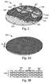
- Fig. 2 shows another exemplary abrasive article 202.
- First filter medium 220 comprises first surface 222 and second surface 224 opposite first surface 222.
- Second filter medium 240 comprises first surface 242 and second surface 244 opposite first surface 242.
- First surface 222 of the first filter medium 220 is proximate apertured coated abrasive member 204.
- Second surface 224 of first filter medium 220 is proximate first surface 242 of second filter medium 240.
- Attachment interface member 246 is affixed to second surface 244 of second filter medium 240.
- Abrasive article 202 differs from abrasive article 102 (shown in Figs.
- weld 226 comprises a continuous network of intersecting line segments 225 situated along second surface 244.
- Weld 226 is situated at second surface 224 of first medium 220 and forms the terminus of puckers 227.
- the weld(s), whether a plurality of discrete welds or a single weld comprising a continuous network of intersecting welded lines or line segments, either of which may be straight or curved, should be substantially evenly distributed across the second surface of the first filter medium in order to provide relatively uniform structural and performance characteristics across the abrasive article. This may be accomplished by a plurality of point welds or welds shaped as lines and/or line segments (that is, relatively short welded lines), or by a welded continuous network of interconnected lines and/or line segments (for example, a honeycomb pattern or a screen pattern).
- the density of welds is at least one and may be, for example, at least, 5, 10, 15, 20, 25, 30, 40, 50, or more per 30 square inches of the second surface of the first filter medium, with the actual number typically chosen such that adequate performance criteria (for example, structural integrity or dust capacity) are met.
- adequate performance criteria for example, structural integrity or dust capacity
- larger abrasive articles will typically have more welds than smaller the density of welds.
- the attachment interface member comprises fabric and may comprise, for example, a loop portion or a hook portion of a two-part mechanical engagement system.
- the attachment interface member may comprise fabric with a layer of pressure sensitive adhesive thereon with an optional release liner to protect it during handling.
- the attachment interface member is porous and allows air to pass through, however this is not a requirement.
- the attachment interface member may comprise a nonwoven, woven or knitted loop fabric, which may be used to affix the abrasive article to a back-up pad having a complementary mating component.
- Woven and knit loop fabrics may have loop-forming filaments or yarns included in their fabric structure to form upstanding loops for engaging hooks.
- Nonwoven loop fabrics may have loops formed by the interlocking fibers.
- the loops are formed by stitching a yarn through the nonwoven web to form upstanding loops.
- Nonwoven fabrics suitable for use as looped fabrics include, for example, airlaid fabrics, spunbond fabrics, spunlaced fabrics, melt blown fabrics, and bonded carded webs.
- Nonwoven fabrics may be bonded in a variety of ways known to those skilled in the art including, for example, needle-punched, stitchbonded, hydroentangled, chemical bond, and thermal bond.
- the woven or nonwoven fabrics used may be made from natural fibers (for example, wood or cotton fibers), synthetic fibers (for example, polyester or polypropylene fibers) or combinations of natural and synthetic fibers.
- the attachment interface member is made from nylon, polyester, polypropylene, or a combination thereof.
- Loop fabrics may have an open structure that does not significantly interfere with the flow of air through it.
- the attachment interface member may comprise a hook material, which may be made in one of many different ways known to those skilled in the art.
- a hook material which may be made in one of many different ways known to those skilled in the art.
- suitable hook materials and processes for making them include, for example, those described in U.S. Pat. Nos. 5,058,247 (Thomas et al. ) and 6,579,161 (Chesley et al. ), and in U.S. Pat. Appln. Publ. No. 2004/0170801 A1 (Seth et al. ).
- the second filter medium may include a wide variety of types of apertured filter media conventionally used in filtration products, particularly air filtration products.
- the second filter medium may be a fibrous material, foam, an apertured membrane, or the like.
- the second filter medium comprises a fibrous material such as, for example, a fibrous filter web such as a nonwoven fibrous web, although woven and knitted webs may also be used.
- the second filter medium comprises fibrous materials having a fiber size that is less than 100 microns in diameter, and sometimes less than 50 microns, and sometimes less than 1 micron in diameter.
- a wide variety of basis weights of the fibrous material may be used in the second filter medium.
- the basis weight of the second filter medium is typically in the range of 5 grams per square meter to 1000 grams per square meter. In some embodiments, the second filter medium is in the range of 10 grams per square meter to 200 grams per square meter. If desired, the second filter medium may include one or more layers (webs) of filter media.
- the second filter medium may be made from a wide variety of organic polymeric materials, including mixtures and blends.
- suitable organic polymeric materials include a wide range of commercially available materials such as: polyolefins such as, for example, polypropylene, linear low density polyethylene, poly-1-butene, poly(4-methyl-1-pentene), polytetrafluoroethylene, polytrifluorochloroethylene, or polyvinyl chloride; aromatic polyarenes such as, for example, polystyrene; polycarbonates; polyesters such as, for example, polyethylene terephthalate or polylactic acid (PLA); and combinations thereof (including blends or copolymers).
- Useful polyolefins may be free of branched alkyl radicals.
- non-thermoplastic fibers such as cellulose, rayon, acrylic, and modified acrylic (halogen modified acrylic); polyamide or polyimide fibers such as those available under the trade designations "NOMEX” and "KEVLAR” from E. I. du Pont de Nemours and Co.; and combinations thereof.
- the nonwoven filter media may be formed in a web by conventional nonwoven techniques including melt blowing, spunbonding, carding, air laying (dry laying), wet laying, or the like.
- the fibers or webs may be charged by known methods, including, for example, by use of corona discharge electrodes or high-intensity electric fields. The fibers may be charged during fiber formation, prior to or while forming the fibers into the filter web or subsequent to forming the filter web. The fibers forming the second media filter may even be charged subsequent to being joined to the first filter media.
- the second filter media may comprise fibers coated with a polymer binder or adhesive, including pressure sensitive adhesives.
- Fig. 3A shows a perspective view of an exemplary first filter medium 320 comprising stacked film layers.
- Fig. 3B shows a top view of a portion of first filter medium 320 shown in Fig. 3A .
- first filter medium 320 has a thickness H that may be varied to accommodate varying applications. For example, if the particular abrading application demands an abrasive article with large particulate holding capacity, the thickness of the first filter medium may be increased.
- the thickness of the first filter medium may be defined by other parameters including, for example, the desired rigidity of the abrasive article.
- the first filter medium of abrasive articles according to the present invention is relatively rigid in comparison to the other filter media used in the abrasive article.
- the first filter medium typically has an average thickness of at least 0.5 millimeter. In some embodiments, the first filter medium has an average thickness of at least 1 millimeter. In yet further embodiments, the first filter medium has an average thickness of at least 3 millimeters.
- first filter medium has an average thickness that is less than 30 millimeters. In some embodiments, the first filter medium has an average thickness that is less than 20 millimeters. In yet further embodiments, the first filter medium has an average thickness that is less than 10 millimeters.
- exemplary first filter medium 320 comprises stack 332 of polymer films that form sidewalls 328 of channels 326 that extend through the thickness of first filter medium 320.
- the sidewalls 328 are held together at bond areas 334.
- First filter medium that may be included in the abrasive article of abrasive articles according to the present invention include, for example, the filter media described in U.S. Pat. No. 6,280,824 (Insley et al. ), U.S. Pat. No. 6,454,839 (Hagglund et al. ), and U.S. Pat. No. 6,589,317 (Zhang et al. ).
- Polymers useful in forming the polymer film sidewalls of a first filter medium include, but are not limited to, polyolefins such as polyethylene and polyethylene copolymers, polypropylene and polypropylene copolymers, polyvinylidene difluoride (PVDF), and polytetrafluoroethylene (PTFE).
- polyolefins such as polyethylene and polyethylene copolymers, polypropylene and polypropylene copolymers, polyvinylidene difluoride (PVDF), and polytetrafluoroethylene (PTFE).
- PVDF polyvinylidene difluoride
- PTFE polytetrafluoroethylene
- Other polymeric materials include acetates, cellulose ethers, polyvinyl alcohols, polysaccharides, polyesters, polyamides, poly(vinyl chloride), polyurethanes, polyureas, polycarbonates, and polystyrene.
- the polymer film layers may be cast from curable resin materials such as acrylates or epoxies and cured through free radical pathways promoted chemically, by exposure to heat, UV, or electron beam radiation.
- the polymer film layers are formed of polymeric material capable of being charged, namely, dielectric polymers and blends such as polyolefins or polystyrenes.
- the polymer film layers may have structured surfaces defined on one or both faces as reported, for example, in U.S. Pat. No. 6,280,824 (Insley et al. ).
- the structured surfaces may be in the shape of upstanding stems or projections, for example, pyramids, cube corners, J-hooks, mushroom heads, or the like; continuous or intermittent ridges; for example, rectangular or v-shaped ridges with intervening channels; or combinations thereof.
- These projections may be regular, random or intermittent or be combined with other structures such as ridges.
- the ridge-type structures may be regular, random intermittent, extend parallel to one another, or be at intersecting or nonintersecting angles and be combined with other structures between the ridges, such as nested ridges or projections.
- the high aspect ratio structures may extend over all or just a region of a film. When present in a film region, the structures provide a surface area greater than a corresponding planar film.
- the structured surfaces may be made by any known method of forming a structured film such as the methods disclosed in U.S. Pat. Nos. 5,069,403 (Marantic et al. ); 5,133,516 (Marantic et al. ); 5,691,846 (Benson et al. ); 5,514,120 (Johnston et al. ); 5,175,030 (Lu et al. ); 4,668,558 (Barber ); 4,775,310 (Fisher ); 3,594,863 (Erb ) or 5,077,870 (Melbye et al. ).
- Fig. 4 shows a perspective view of another exemplary first filter medium comprising a perforated body.
- first filter medium 420 comprises channels 426 with channel sidewalls 428 extending from the first surface to the second surface of the first filter medium.
- the filter medium shown in Fig. 4 may be constructed from a variety of materials including, for example, foam, paper, or plastic, including molded thermoplastic materials and molded thermoset materials.
- the first filter medium is made from perforated apertured foam material.
- the first filter medium is made from perforated or slit and stretched sheet materials.
- the perforated body is made from fiberglass, nylon, polyester, or polypropylene.
- the first filter medium has discrete channels that extend from the first surface to the second surface of the first filter medium.
- the channels may have a non-tortuous path that extends directly from the first surface to the second surface of the first filter medium.
- the cross-sectional area of the channels may be described in terms of an effective circular diameter, which is the diameter of the largest circle that will pass through an individual channel.
- the first filter media have channels with an average effective circular diameter of at least 0.1 millimeter, although this is not a requirement. In some embodiments, the first filter medium has channels with an average effective circular diameter of at least 0.3 millimeters. In yet further embodiments, the first filter medium has channels with an average effective circular diameter of at least 0.5 millimeters.
- first filter medium has channels with an average effective circular diameter that is less than 2 millimeters. In some embodiments, the first filter medium has channels with an average effective circular diameter that is less than 1 millimeter. In yet further embodiments, the first filter medium have channels with an average effective circular diameter that is less than 0.5 millimeters.
- the filter media including the first and second filter media, of abrasive articles according to the present invention may be electrostatically charged. Electrostatic charging enhances the filter media's ability to remove particulate matter from a fluid stream by increasing the attraction between particles and the surface of the filter media. Non-impinging particles passing close to sidewalls are more readily pulled from the fluid stream, and impinging particles are adhered more strongly. Passive electrostatic charging is provided by an electret, which is a dielectric material that exhibits an electrical charge that persists for extended time periods.
- Electret chargeable polymeric materials include nonpolar polymers such as polytetrafluoroethylene (PTFE) and polypropylene.
- any of which may be used to charge the filtration media of the abrasive article of the present invention including corona discharge, heating and cooling the material in the presence of a charged field, contact electrification, spraying the web with charged particles, and impinging a surface with water jets or water droplet streams.
- the chargeability of the surface may be enhanced by the use of blended materials.
- known charging methods include those disclosed in: U.S. Pat. No. RE30,782 (van Turnhout et al. ), U.S. Pat. No. RE31,285 (van Turnhout et al. ), U.S. Pat. No. 5,496,507 (Angadjivand et al.
- the first and second filter media may be bonded together prior to joining them to the attachment interface member.
- Useful bonding techniques include adhesives and ultrasonic welding.
- Ultrasonic welding is a well-known technique that involves the use of high frequency sound energy to melt and fuse together materials to be welded. Ultrasonic welding equipment is widely commercially available. In an ultrasonic welding process, the pieces to be welded are held together under pressure between to elements commonly termed the “anvil” (a passive element) and “horn” (an ultrasonically vibrating element), and are then subject to ultrasonic vibrations, usually at a frequency of 20 to 40 kHz. Mechanical vibratory energy at an ultrasonic frequency is transferred from the welding horn to the compressed material thereby forming an ultrasonic weld. The horn and the anvil may have any shape.
- whichever of the horn or the anvil that has a smaller contact area will tend to penetrate the item to be welded more rapidly than the other. In such cases, it is typically useful to arrange the welding apparatus such that whichever of the horn or the anvil that has a smaller contact area contacts the first surface of the first filter medium during welding.
- the time required to form the weld is typically less than one second, but will depend on factors such as the vibration amplitude, and the type of materials being welded. Further to the last point, ultrasonic welding is typically not effective with materials that cannot fuse together to form a weld. For this reason, at least a portion of the first filter medium, second filter medium, and the attachment interface member are typically selected such that they are of the same or similar materials that are melt compatible.
- the first and second filter media may comprise polypropylene, while the attachment interface member comprises a fiber blend of nylon and polypropylene.
- an apertured coated abrasive member is adhered to the first filter medium by a layer of pressure sensitive adhesive.
- FIG. 5A shows a top view of an exemplary apertured coated abrasive member 504.
- Fig. 5B shows a cross-sectional view of a section of apertured coated abrasive member 504 (shown in Fig. 5A ).
- apertured coated abrasive member 504 comprises thin flexible incompressible backing 506 having first surface 508 and second surface 510, make coat 514, abrasive particles 512, and size coat 515.
- apertured coated abrasive member 504 comprises apertures 516 (not shown in Fig. 5B ).
- the thin flexible incompressible backing may be made from metal, paper, or plastic film (for example, including for example thermoplastic materials such as polyester, polyethylene, and polypropylene).
- Examples of commercially available apertured coated abrasive articles include material available under the trade designation "NORTON MULTI-AIR", from Saint-Gobain Abrasives GmbH, Wesseling, Germany, and coated abrasive discs available under the trade designation “360L MULTIHOLE HOOKIT” from 3M Company, Saint Paul. Minnesota.
- Examples of commercially available coated abrasive articles that may be perforated (for example, by a die or laser) to provide apertured coated abrasive articles include abrasive material available under the trade designation "373L MICRON MICROFINISHING FILM" from 3M Company.
- the mode of carrying out the ultrasonic welding step influences the product performance of the resultant abrasive article. For example, if the anvil is placed against the first filter medium and the horn is placed against the attachment interface member, then weld(s) are typically formed at the first surface of the first filter medium, while if the horn is placed against the first filter medium and the anvil is placed against the attachment interface member, then weld(s) are typically formed at the second surface of the first filter medium.
- the apertured coated abrasive member comprises abrasive particles secured to the backing by make layer and size layers, and optionally a supersize layer.
- a treatment may be applied to the substrate such as, for example, a presize, a backsize, a subsize, or a saturant.
- the make layer of a coated abrasive is prepared by coating at least a portion of the substrate (treated or untreated) with a make layer precursor.
- Abrasive particles are then at least partially embedded (for example, by electrostatic coating) to the make layer precursor comprising a first binder precursor, and the make layer precursor is at least partially cured.
- Electrostatic coating of the abrasive particles typically provides erectly oriented abrasive particles, wherein the term "erectly oriented" refers to a characteristic in which the longer dimensions of a majority of the abrasive particles are oriented substantially perpendicular (that is, between 60 and 120 degrees) to the backing. Other techniques for erectly orienting abrasive particles may also be used.
- the size layer is prepared by coating at least a portion of the make layer and abrasive particles with a size layer precursor comprising a second binder precursor (which may be the same as, or different from, the first binder precursor), and at least partially curing the size layer precursor.
- a supersize is applied to at least a portion of the size layer. If present, the supersize layer typically includes grinding aids and/or anti-loading materials.
- make and size layers are formed by curing (for example, by thermal means, or by using electromagnetic or particulate radiation) the corresponding make layer precursor and size layer precursor.
- Useful make layer and size layer precursors are well known in the abrasive art and include, for example, free-radically polymerizable monomer and/or oligomer, epoxy resins, acrylic resins, urethane resins, phenolic resins, urea-formaldehyde resins, melamine-formaldehyde resins, aminoplast resins, cyanate resins, or combinations thereof.
- Useful make layer and size layer precursors include thermally curable resins and radiation curable resins, which may be cured, for example, thermally and/or by exposure to radiation.
- Suitable abrasive particles for the coated abrasives useful in the present invention may be any known abrasive particles or materials commonly used in abrasive articles.
- useful abrasive particles for coated abrasives include, for example, fused aluminum oxide, heat treated aluminum oxide, white fused aluminum oxide, black silicon carbide, green silicon carbide, titanium diboride, boron carbide, tungsten carbide, titanium carbide, diamond, cubic boron nitride, garnet, fused alumina zirconia, sol gel abrasive particles, silica, iron oxide, chromia, ceria, zirconia, titania, silicates, metal carbonates (such as calcium carbonate (for example, chalk, calcite, marl, travertine, marble and limestone), calcium magnesium carbonate, sodium carbonate, magnesium carbonate), silica (for example, quartz, glass beads, glass bubbles and glass fibers) silicates (for example, talc, clays, (
- the abrasive particles may also be agglomerates or composites that include additional components, such as, for example, a binder. Criteria used in selecting abrasive particles used for a particular abrading application typically include: abrading life, rate of cut, substrate surface finish, grinding efficiency, and product cost.
- Abrasive particles according to the present invention may be used in a wide range of particle sizes, typically ranging in size from 0.1 to 5000 micrometers, more typically from 1 to 2000 micrometers; typically from 5 to 1500 micrometers, and more typically from 10 to 1500 micrometers.
- the abrasive particles are typically selected according to standard abrasives industry grading standards (for example, ANSI, JIS or FEPA grades), although this is not a requirement.
- Abrasive particles graded according to industry accepted grading standards specify the particle size distribution for each nominal grade within numerical limits.
- industry accepted grading standards include those known as the American National Standards Institute, Inc. (ANSI) standards, Federation of European Producers of Abrasive Products (FEPA) standards, and Japanese Industrial Standard (JIS) standards.
- Exemplary ANSI grade designations include: ANSI 4, ANSI 6, ANSI 8, ANSI 16, ANSI 24, ANSI 36, ANSI 40, ANSI 50, ANSI 60, ANSI 80, ANSI 100, ANSI 120, ANSI 150, ANSI 180, ANSI 220, ANSI 240, ANSI 280, ANSI 320, ANSI 360, ANSI 400, and ANSI 600.
- Exemplary FEPA grade designations include P8, P12, P16, P24, P36, P40, P50, P60, P80, P100, P120, P150, P180, P220, P320, P400, P500, 600, P800, P1000, and P1200.
- Exemplary JIS grade designations include HS8, JIS12, JIS16, JIS24, JIS36, JIS46, JIS54, JIS60, JIS80, JIS 100, JIS 150, JIS 180, JIS220, JIS 240, JIS280, JIS320, JIS360, JIS400, JIS400, JIS600, JIS800, JIS1000, JIS1500, JIS2500, JIS4000, JIS6000, JIS8000, and JIS10,000.
- the abrasive particles have an average particle size of 50 micrometers or less; for example, 40 micrometers or less, or even 30 micrometers or less.
- Useful apertured coated abrasives may further comprise optional additives such as abrasive particle surface modification additives, coupling agents, plasticizers, fillers, expanding agents, fibers, antistatic agents, initiators, suspending agents, photosensitizers, lubricants, wetting agents, surfactants, pigments, dyes, UV stabilizers, and suspending agents.
- optional additives such as abrasive particle surface modification additives, coupling agents, plasticizers, fillers, expanding agents, fibers, antistatic agents, initiators, suspending agents, photosensitizers, lubricants, wetting agents, surfactants, pigments, dyes, UV stabilizers, and suspending agents.
- additives such as abrasive particle surface modification additives, coupling agents, plasticizers, fillers, expanding agents, fibers, antistatic agents, initiators, suspending agents, photosensitizers, lubricants, wetting agents, surfactants, pigments, dyes, UV stabilizers, and suspending
- the apertured coated abrasive member may comprise apertures having different open areas.
- the "open area" of an aperture refers to the area of the opening as measured over the thickness of the apertured coated abrasive member (that is, the area bounded by the perimeter of material forming the opening through which a three-dimensional object could pass).
- Apertured abrasive layers useful in the present invention typically have an average open area of at least 0.5 square millimeters per opening.
- the apertured coated abrasive member has an average open area of at least 1 square millimeter per opening; for example, the apertured coated abrasive member may have an average open area of at least 1.5 square millimeters per opening.
- the apertured coated abrasive member has an average open area that is less than 4 square millimeters per opening. In some embodiments, the apertured coated abrasive member has an average open area that is less than 3 square millimeters per opening; for example, the apertured coated abrasive member has an average open area that is less than 2.5 square millimeters per opening.
- the apertured coated abrasive member comprises a total open area that affects the amount of air that can pass through the apertured coated abrasive member as well as the effective area and performance of the abrasive member.
- the "total open area" of the apertured coated abrasive member refers to the cumulative open areas of the openings as measured over the area formed by the perimeter of the apertured coated abrasive member.
- Apertured abrasive members useful in the present invention have a total open area of at least 0.01 square centimeters per square centimeter of the abrasive member (that is, 1 percent open area).
- the apertured coated abrasive member has a total open area of at least 0.03 square centimeters per square centimeter of the abrasive member (that is, 3 percent open area). In yet further embodiments, the apertured coated abrasive member has a total open area of at least 0.05 square centimeters per square centimeter of the abrasive member (that is, 5 percent open area).
- apertured coated abrasive members have a total open area that is less than 0.95 square centimeters per square centimeter of the abrasive member (that is, 95 percent open area). In some embodiments, the apertured coated abrasive member has a total open area that is less than 0.9 square centimeters per square centimeter of the abrasive member (that is, 90 percent open area). In yet further embodiments, the apertured coated abrasive member has a total open area that is less than 0.8 square centimeters per square centimeter of the abrasive member (that is, 80 percent open area).
- the apertures may be arranged according to a pattern or in a random or pseudo-random manner.
- the various layers in abrasive articles according to the present invention may be held together using any suitable form of attachment such as, for example, glue, pressure sensitive adhesive, hot-melt adhesive, spray adhesive, thermal bonding, and ultrasonic bonding.
- some of the layers are adhered to one another by applying a spray adhesive such as, for example, that available under the trade designation "3M SUPER 77 ADHESIVE", available from 3M Company, St. Paul, Minnesota, to one side of the porous abrasive.
- a hot-melt adhesive is applied to one side of a layer using either a hot-melt spray gun or an extruder with a comb-type shim.
- a preformed adhesive mesh is placed between some of the layers to be joined.
- the apertured coated abrasive member and various filter media layers of abrasive articles according to the present invention are affixed to one another in a manner that does not prevent the flow of particles from one layer to the next.
- the apertured coated abrasive member and various filter media layers of abrasive articles according to the present invention are affixed to one another in a manner that does not substantially inhibit the flow of particles from one layer to the next.
- the level of particle flow through the abrasive article may be restricted, at least in part, by the introduction of an adhesive between the apertured coated abrasive member and the first filter medium, or the first filter medium and the second filter medium.
- the level of restriction may be minimized by applying the adhesive between layers in a discontinuous fashion such as for example, as discrete adhesive areas (for example, atomized spray or starved extrusion die) or distinct adhesive lines (for example, hot melt swirl-spray or patterned roll coater).
- discrete adhesive areas for example, atomized spray or starved extrusion die
- distinct adhesive lines for example, hot melt swirl-spray or patterned roll coater
- the attachment interface member of abrasive articles according to the present invention is affixed to the filter media in a manner that does not prevent the flow of air from the filter media.
- the attachment interface member of abrasive articles according to the present invention is affixed to the filter media in a manner that does not substantially inhibit the flow of air from the filter media.
- the level of air flow through the attachment interface member may be restricted, at least in part, by the introduction of an adhesive between an attachment interface member comprising a sheet material and the filter media.
- the level of restriction may be minimized by applying the adhesive between the sheet material of the attachment interface member and the filter media in a discontinuous fashion such as, for example, discrete adhesive areas (for example, atomized spray or starved extrusion die) or distinct adhesive lines (for example, hot melt swirl-spray or patterned roll coater).
- discrete adhesive areas for example, atomized spray or starved extrusion die
- distinct adhesive lines for example, hot melt swirl-spray or patterned roll coater
- Adhesives useful in the present invention include both pressure sensitive and non-pressure sensitive adhesives.
- Pressure sensitive adhesives arc normally tacky at room temperature and may be adhered to a surface by application of, at most, light finger pressure, while non-pressure sensitive adhesives include solvent, heat, or radiation activated adhesive systems.
- adhesives useful in the present invention include those based on general compositions of polyacrylate; polyvinyl ether; diene-containing rubbers such as natural rubber, polyisoprene, and polyisobutylene; polychloroprene; butyl rubber; butadiene-acrylonitrile polymers; thermoplastic elastomers; block copolymers such as styrene-isoprene and styrene-isoprene-styrene block copolymers, ethylenepropylene-diene polymers, and styrene-butadiene polymers; poly(alpha-olefin)polymers; amorphous polyolefins; silicone; ethylene-containing copolymers such as ethylene vinyl acetate, ethyl acrylate, and ethyl methacrylate; polyurethanes; polyamides; polyesters; epoxies; polyvinylpyrrolidone and vinylpyr
- a coated abrasive material commercially available under the trade designation "373L 30 MICRON MICROFINISHING FILM", from 3M Company, having laser perforated 4.57 millimeter diameter holes at a frequency of 1.37 holes per square centimeter.
- a 50% aqueous calcium stearate dispersion commercially available under the trade designation "E-1058", from E-Chem, Leeds, England, was applied to the size layer and dried for 10 minutes at 48.9°C (120°C).
- the dry coating weight of calcium stearate in the supersize layer was 6.8 grams per square meter (g/m 2 ).
- a coated abrasive material commercially available under the trade designation "373L 50 MICRON MICROFINISH1NG FILM", from 3M Company, having laser perforated 4.57 millimeter diameter holes at a frequency of 1.37 holes per square centimeter.
- a supersize of calcium stearate of 6.8 g/m 2 was applied according to the same procedure as described in abrasive material A1.
- A3 A screen abrasive commercially available under the trade designation "ABRANET GRADE P600” from KWH Mirka Ltd., Jeppo, Finland.
- A4 A coated abrasive material, commercially available under the trade designation "373L 40 MICRON MICROFINISHING FILM", from 3M Company, having laser perforated 4.57 millimeter diameter holes at a frequency of 1.37 holes per square centimeter.
- A5 A nonwoven abrasive material, commercially available under the trade designation “07748 COLOR PREP SCUFF”, from 3M Company, St. Paul, Minnesota.
- A6 A coated abrasive material as in "A5", with an addition layer of 5 mm thick bare polyurethane foam, 0.1 gram/cm 3 (6 lb/ft 3 ) density, commercially available under the trade designation "R600U” from I11bruck, Inc., Minneapolis, Minnesota.
- F1 5 millimeter thick corrugated polypropylene multilayer filter media commercially available under the trade designation "3M High Airflow Air Filtration Media (HAF)” from 3M Company.
- F2 An electrostatically charged staple fiber web, 100 gsm basis weight, with 2 percent of its overall surface area uniformly point bonded using ultrasonic welding, commercially available under the trade designation "FILTRETE G100” from 3M Company.
- AT1 A loop attachment material commercially available under the trade designation "70 G/M 2 TRICOT DAYTONA BRUSHED NYLON LOOP FABRIC” from Sitip SpA, Genoa, Italy.
- AT2 A loop attachment material obtained under the trade designation "85 G/M 2 TRICOT DAYTONA BRUSHED POLYPROPYLENE LOOP FABRIC" from Sitip SpA.
- AT3 A loop attachment material obtained under the trade designation "110 G/M 2 TRICOT DAYTONA BRUSHED POLYPROPYLENE LOOP FABRIC" from Sitip SpA.
- a 12.7 centimeter (cm) (5-inch) sample disc to be evaluated was attached to a 12.7-cm diameter by 0.95 cm (3/8-inch) thick foam backup pad, available under the trade designation "DYNABRADE BACK-UP PAD, MODEL 56320” from Dynabrade Corporation, Clarence, New York.
- the backup pad and disc assembly was weighed, then mounted onto a dual-action orbital sander, model "21038", also obtained from Dynabrade Corporation.
- the central dust extraction vacuum line was detached from the sander.
- the abrasive face of the disc was automatically brought into contact with a pre-weighed 45.7-cm by 76.2-cm (18-inch by 30-inch) gel-coated fiberglass reinforced plastic panel, obtained from White Bear Boat Works, White Bear Lake, Minnesota.
- the sander was run at 630.9 kilopascals (kPa) (91.5 pounds per square inch) air line pressure and a down force of (66.7 N) 15 pounds force). An angle of zero degrees to the surface of the workpiece was used.
- Each test consisted of 24 or 48 overlapping transverse passes, 53.3 cm (21 inches) in length, resulting in an evenly sanded 45.7 by 66.0 cm (18 by 26 inch) area of test panel.
- Tool motion over the face of the panel was at a rate of 12.7 cm/sec (5 inches/second) for both X and Y directions. After the final sanding pass, the test panel and sample with backup pad were re-weighed. The test panel was then cleaned and weighed again. The sample was removed from the backup pad and the backup pad and tool were cleaned in preparation for another test.
- the laminate was then ultrasonically welded using a model "DUKANE 3000 AUTO TRAC 20 KHZ ULTRASONIC WELDER ", obtained from Dukane Intelligent Assembly Solutions, St. Charles, Illinois.
- Welding conditions were as follows: Weld Energy 1,100 Joules Trigger Force 133.5 Newtons (N) (30 pounds-force (lbf)) Weld Force 2,046 N (460 lbf) Horn Amplitude (35.6 micrometers) 0.0014 inches peak to peak Maximum Weld Time 2.0 seconds Hold Time 1.0 second Anvil Multi 2.5 by 2.5 mm base by 6.4 mm height square steel posts Horn 12.7x12.7 cm 5x5 inch aluminum block horn Laminate Orientation Horn adjacent to L2 Weld Shape/Size approximately 2.5 mm by 2.5mm square Weld Pattern Uniformly distributed hexagonal array with 2.1 cm spacing, approximately 37 welds/disc
- Abrasive discs were prepared according to the method described in Comparative A, except abrasive material A3 was used instead of A2.
- Abrasive discs were prepared according to the method described in Comparative A, except attachment material AT3 was used instead of AT1, and the welding orientation was reversed.
- Abrasive discs were prepared according to the method described in Example B, except the welding orientation was reversed.
- Abrasive discs were prepared according to the method described in Comparative Example A, except A4 was used as the abrasive material.
- Abrasive discs were prepared according to the method described in Comparative Example C, except the welding orientation was reversed.
- Abrasive discs were prepared according to the method described in Example D except the welding orientation was reversed.
- Abrasive discs were prepared according to the method described in Comparative Examples A and Example 3, corresponding to Comparatives E and F, respectively, except that A5 was used as the abrasive material. Results reported in Table 4 represent sanding data for 48 passes per test.
- Abrasive discs were prepared according to the method described in Comparative Examples A and Example 3, corresponding to Comparatives G and H, respectively, except that A3 was used as the abrasive material. Results reported in Table 4 represent sanding data for 48 passes per test.
- Abrasive discs were prepared according to the method described in Comparative Examples A and Example 4, corresponding to Comparatives I and J, respectively, except that A6 was used as the abrasive material.
Claims (15)
- Schleifgegenstand (102), welcher Folgendes aufweist:ein beschichtetes Schleifelement (104, 504) mit Öffnungen, welches Schleifteilchen (512) aufweist, die durch Grund- und Deckschichten (514, 515) an einer ersten Hauptfläche (508) einer dünnen, flexiblen, nicht komprimierbaren Trägerschicht (506) befestigt sind; undeine Haftschicht, die an einer zweiten Hauptfläche (510) gegenüber der ersten Hauptfläche der Trägerschicht (506) haftet, wobei sich durch die Schleifschicht, die Trägerschicht (506) und die Haftschicht Öffnungen (115, 516) erstrecken;ein erstes Filtermedium (120, 220, 320, 420), welches eine erste Fläche (122, 222) und eine zweite Fläche (124, 224) gegenüber der ersten Fläche (122, 222) aufweist, wobei die erste Fläche (122, 222) des ersten Filtermediums (120, 220, 320, 420) an der Haftschicht des beschichteten Schleifelements (104, 504) mit Öffnungen haftet, wobei das erste Filtermedium (120, 220, 320, 420) diskrete Kanäle (326, 426) definiert, die durch Kanalseitenwände (328, 428) gebildet werden, wobei sich die diskreten Kanäle (326, 426) von der ersten Fläche (122, 222) des ersten Filtermediums (120, 220, 320, 420) bis zu der zweiten Fläche (124, 224) des ersten Filtermediums (120, 220, 320, 420) erstrecken;ein zweites Filtermedium (140, 240), welches erste und zweite sich gegenüberliegende Flächen (242, 244) aufweist, wobei die erste Fläche (242) des zweiten Filtermediums (140, 240) an einer Grenzfläche an die zweite Fläche (124, 224) des ersten Filtermediums (120, 220, 320, 420) anschließt; undein Befestigungsgrenzelement (146, 246), welches an der zweiten Fläche (244) des zweiten Filtermediums (140, 240) befestigt ist, wobei das Befestigungsgrenzelement (146, 246) ein Gewebe aufweist und eine hintere Fläche aufweist, die an das zweite Filtermedium (140, 240) anschließt, und eine nach außen angeordnete, in Eingriff zu bringende Fläche gegenüber der hinteren Fläche aufweist;wobei zumindest ein Teil der Öffnungen mit zumindest einem Teil der diskreten Kanäle (326, 426) zusammenwirkt, um zu ermöglichen, dass Teilchen von dem beschichteten Schleifelement (104, 504) mit Öffnungen zu dem zweiten Filtermedium (140, 240) gelangen, wobei das erste Filtermedium (120, 220, 320, 420), das zweite Filtermedium (140, 240) und das Befestigungsgrenzelement (146, 246) durch mindestens eine Schweißnaht (125, 226) miteinander verbunden sind, die sich an der Grenzfläche befindet.
- Schleifgegenstand nach Anspruch 1, wobei das erste Filtermedium, das zweite Filtermedium und das Befestigungsgrenzelement durch eine Schweißnaht miteinander verbunden sind, welche ein durchgängiges Netz sich schneidender Linien oder Liniensegmente aufweist.
- Schleifgegenstand nach Anspruch 1, wobei die Kanalseitenwände Polymerfilme aufweisen.
- Schleifgegenstand nach Anspruch 1, wobei das zweite Filtermedium einen Vliesfilter aufweist.
- Schleifgegenstand nach Anspruch 1, wobei mindestens eines aus dem ersten Filtermedium und dem zweiten Filtermedium eine Elektretladung aufweist.
- Schleifgegenstand nach Anspruch 1, wobei das Befestigungsgrenzelement einen Ösenteil eines zweiteiligen mechanischen Eingriffssystems aufweist.
- Schleifgegenstand nach Anspruch 1, wobei das erste Filtermedium, das zweite Filtermedium und das Befestigungsgrenzelement jeweils Polypropylen aufweisen.
- Schleifgegenstand nach Anspruch 1, wobei der Schleifgegenstand eine Schleifscheibe aufweist.
- Verfahren zum Schleifen einer Fläche eines Werkstücks, welches das reibschlüssige In-Kontakt-Bringen der Fläche des Werkstücks mit einem Schleifgegenstand (102) nach Anspruch 1 und das Bewegen des Schleifgegenstands (102) relativ zu der Fläche umfasst, um die Fläche zu schleifen.
- Verfahren zum Schleifen einer Fläche eines Werkstücks nach Anspruch 9, wobei das erste Filtermedium, das zweite Filtermedium und das Befestigungsgrenzelement jeweils Polypropylen aufweisen.
- Verfahren zur Herstellung eines Schleifgegenstands (102), wobei das Verfahren Folgendes umfasst:Bereitstellen eines beschichteten Schleifelements (104, 504) mit Öffnungen, welches Schleifteilchen (512) aufweist, die durch Grund- und Deckschichten (514, 515) an einer ersten Hauptfläche (508) einer dünnen, flexiblen, nicht komprimierbaren Trägerschicht (506) befestigt sind; undeiner Haftschicht, die an einer zweiten Hauptfläche (510) gegenüber der ersten Hauptfläche (508) der Trägerschicht (506) haftet, wobei sich durch die Schleifschicht, die Trägerschicht (506) und die Haftschicht Öffnungen (115, 516) erstrecken;Bereitstellen eines ersten Filtermediums (120, 220, 320, 420), welches eine erste Fläche (122, 222) und eine zweite Fläche (124, 224) gegenüber der ersten Fläche (122, 222) aufweist, wobei das erste Filtermedium (120, 220, 320, 420) diskrete Kanäle (326, 426) definiert, die durch Kanalseitenwände (328, 428) gebildet werden, wobei sich die diskreten Kanäle (326, 426) von der ersten Fläche (122, 222) des ersten Filtermediums (120, 220, 320, 420) bis zu der zweiten Fläche (124, 224) des ersten Filtermediums (120, 220, 320, 420) erstrecken;Bereitstellen eines zweiten Filtermediums (140, 240), welches erste und zweite sich gegenüberliegende Flächen (242, 244) aufweist,Bereitstellen eines Befestigungsgrenzelements (146, 246), welches ein Gewebe aufweist und eine hintere Fläche und eine in Eingriff zu bringende Fläche gegenüber der hinteren Fläche aufweist;In-Kontakt-Bringen der ersten Fläche (242) des zweiten Filtermediums (140, 240) mit der zweiten Fläche (124, 224) des ersten Filtermediums (120, 220, 320, 420);In-Kontakt-Bringen der hinteren Fläche des Befestigungsgrenzelements (146, 246) mit der zweiten Fläche (244) des zweiten Filtermediums (140, 240);Bilden mindestens einer Schweißnaht (125, 226), welche das erste Filtermedium (120, 220, 320, 420), das zweite Filtermedium (140, 240) und das Befestigungsgrenzelement (146, 246) verbindet, wobei sich die Schweißnaht (125, 226) an der zweiten Fläche (124, 224) des ersten Mediums (120, 220, 320, 420) befindet; undKleben der Haftschicht des beschichteten Schleifelements (104, 504) mit Öffnungen auf die erste Fläche (122, 222) des ersten Filtermediums (120, 220, 320, 420);wobei zumindest ein Teil der Öffnungen (115, 516) mit zumindest einem Teil der diskreten Kanäle (326, 426) zusammenwirkt, um zu ermöglichen, dass Teilchen von dem beschichteten Schleifelement (104, 504) mit Öffnungen zu dem zweiten Filtermedium (140, 240) gelangen.
- Verfahren nach Anspruch 11, wobei das erste Filtermedium, das zweite Filtermedium und das Befestigungsgrenzelement durch eine Schweißnaht miteinander verbunden werden, welche ein durchgängiges Netz sich schneidender Liniensegmente aufweist.
- Verfahren nach Anspruch 11, welches vor dem Verbinden des ersten Filtermediums, des zweiten Filtermediums und des Befestigungsgrenzelements ferner das Verbinden des ersten Filtermediums mit dem zweiten Filtermedium umfasst.
- Verfahren nach Anspruch 11, wobei das erste Filtermedium, das zweite Filtermedium und das Befestigungsgrenzelement jeweils Polypropylen aufweisen.
- Verfahren nach Anspruch 11, wobei die mindestens eine Schweißnaht durch ein Verfahren gebildet wird, welches Folgendes umfasst:In-Kontakt-Bringen der ersten Fläche des ersten Filtermediums mit einem Ultraschallschweißdorn oder -amboss, In-Kontakt-Bringen der in Eingriff zu bringenden Fläche des Befestigungsgrenzelements mit dem anderen aus dem Ultraschallschweißdorn oder -amboss und Bilden mindestens einer Schweißnaht durch Ultraschall, mit welcher das erste Filtermedium, das zweite Filtermedium und das Befestigungsgrenzelement verbunden werden.
Applications Claiming Priority (2)
| Application Number | Priority Date | Filing Date | Title |
|---|---|---|---|
| US11/423,829 US7338355B2 (en) | 2006-06-13 | 2006-06-13 | Abrasive article and methods of making and using the same |
| PCT/US2007/070094 WO2007146608A2 (en) | 2006-06-13 | 2007-05-31 | Abrasive article and methods of making and using the same |
Publications (3)
| Publication Number | Publication Date |
|---|---|
| EP2035189A2 EP2035189A2 (de) | 2009-03-18 |
| EP2035189A4 EP2035189A4 (de) | 2010-09-08 |
| EP2035189B1 true EP2035189B1 (de) | 2012-03-21 |
Family
ID=38822545
Family Applications (1)
| Application Number | Title | Priority Date | Filing Date |
|---|---|---|---|
| EP07811982A Not-in-force EP2035189B1 (de) | 2006-06-13 | 2007-05-31 | Schleifartikel und verfahren zu seiner herstellung und verwendung |
Country Status (6)
| Country | Link |
|---|---|
| US (1) | US7338355B2 (de) |
| EP (1) | EP2035189B1 (de) |
| JP (1) | JP2009539638A (de) |
| CN (1) | CN101466500B (de) |
| AT (1) | ATE550147T1 (de) |
| WO (1) | WO2007146608A2 (de) |
Families Citing this family (20)
| Publication number | Priority date | Publication date | Assignee | Title |
|---|---|---|---|---|
| US20080233850A1 (en) * | 2007-03-20 | 2008-09-25 | 3M Innovative Properties Company | Abrasive article and method of making and using the same |
| US7628829B2 (en) * | 2007-03-20 | 2009-12-08 | 3M Innovative Properties Company | Abrasive article and method of making and using the same |
| US20080318506A1 (en) * | 2007-06-19 | 2008-12-25 | John Edward Brown | Abrasive article and method of making |
| AU2008346787B2 (en) * | 2007-12-31 | 2011-04-28 | Saint-Gobain Abrasifs | Interface pad for use between an abrasive article and a support tool |
| WO2009111613A2 (en) * | 2008-03-07 | 2009-09-11 | Saint-Gobain Abrasives, Inc. | Floor sanding sponge pads |
| US20100075578A1 (en) * | 2008-09-19 | 2010-03-25 | Hung-Ke Chou | Abrasive polishing net with a stickable fiber layer |
| US10137556B2 (en) * | 2009-06-22 | 2018-11-27 | 3M Innovative Properties Company | Shaped abrasive particles with low roundness factor |
| WO2010077826A2 (en) * | 2008-12-30 | 2010-07-08 | Saint-Gobain Abrasives, Inc. | Multi-air aqua reservoir moist sanding system |
| GB0904770D0 (en) * | 2009-03-20 | 2009-05-06 | Brentnall Nicholas | Filter and method of manufacture |
| CN103328157B (zh) | 2011-02-16 | 2017-03-22 | 3M创新有限公司 | 具有旋转对齐的成形陶瓷磨粒的带涂层磨料制品 |
| EP2758210B1 (de) * | 2011-09-20 | 2016-05-18 | Robert Bosch GmbH | Haltekörper für flexibles schleifmittel, schleifsystem und schleifgerät |
| US9644283B2 (en) * | 2011-09-30 | 2017-05-09 | Apple Inc. | Laser texturizing and anodization surface treatment |
| CN203210209U (zh) * | 2013-04-03 | 2013-09-25 | 淄博理研泰山涂附磨具有限公司 | 一种防堵塞网眼砂布 |
| TWI589406B (zh) * | 2013-06-28 | 2017-07-01 | 聖高拜磨料有限公司 | 具有浮渣脊之研磨製品及其形成方法 |
| CA2931631C (en) * | 2013-12-06 | 2018-06-19 | Saint-Gobain Abrasives, Inc. | Coated abrasive article including a non-woven material |
| WO2018025209A1 (en) | 2016-08-02 | 2018-02-08 | Fitesa Germany Gmbh | System and process for preparing polylactic acid nonwoven fabrics |
| US11441251B2 (en) | 2016-08-16 | 2022-09-13 | Fitesa Germany Gmbh | Nonwoven fabrics comprising polylactic acid having improved strength and toughness |
| CN112512748A (zh) * | 2018-07-23 | 2021-03-16 | 3M创新有限公司 | 包括聚酯背衬和底漆层的制品及相关方法 |
| WO2020026060A1 (en) * | 2018-07-30 | 2020-02-06 | 3M Innovative Properties Company | Self-contained buffing articles |
| CN112536736A (zh) * | 2020-12-28 | 2021-03-23 | 常州冠日电器工具有限公司 | 一种研磨页轮加工工艺 |
Family Cites Families (74)
| Publication number | Priority date | Publication date | Assignee | Title |
|---|---|---|---|---|
| US3420007A (en) | 1966-07-11 | 1969-01-07 | Wallace Murray Corp | Abrasive tool |
| US3594863A (en) * | 1969-07-10 | 1971-07-27 | American Velcro Inc | Apparatus for molding plastic shapes in molding recesses formed in a moving endless belt |
| US3861892A (en) * | 1973-02-08 | 1975-01-21 | Norton Co | Coated abrasive material and manner of manufacture |
| NL160303C (nl) * | 1974-03-25 | 1979-10-15 | Verto Nv | Werkwijze voor het vervaardigen van een vezelfilter. |
| GB1466545A (en) * | 1974-03-26 | 1977-03-09 | Nederman B | Abrasive disc |
| NL181632C (nl) * | 1976-12-23 | 1987-10-01 | Minnesota Mining & Mfg | Electreetfilter en werkwijze voor het vervaardigen daarvan. |
| US4215682A (en) * | 1978-02-06 | 1980-08-05 | Minnesota Mining And Manufacturing Company | Melt-blown fibrous electrets |
| US4668558A (en) * | 1978-07-20 | 1987-05-26 | Minnesota Mining And Manufacturing Company | Shaped plastic articles having replicated microstructure surfaces |
| US4287685A (en) * | 1978-12-08 | 1981-09-08 | Miksa Marton | Pad assembly for vacuum rotary sander |
| US4282011A (en) | 1980-05-30 | 1981-08-04 | Dan River Incorporated | Woven fabrics containing glass fibers and abrasive belts made from same |
| US4374888A (en) * | 1981-09-25 | 1983-02-22 | Kimberly-Clark Corporation | Nonwoven laminate for recreation fabric |
| JPS60168511A (ja) * | 1984-02-10 | 1985-09-02 | Japan Vilene Co Ltd | エレクトレツトフイルタの製造方法 |
| US4775310A (en) * | 1984-04-16 | 1988-10-04 | Velcro Industries B.V. | Apparatus for making a separable fastener |
| US4609581A (en) * | 1985-04-15 | 1986-09-02 | Minnesota Mining And Manufacturing Company | Coated abrasive sheet material with loop attachment means |
| US4986496A (en) * | 1985-05-31 | 1991-01-22 | Minnesota Mining And Manufacturing | Drag reduction article |
| US5133516A (en) * | 1985-05-31 | 1992-07-28 | Minnesota Mining And Manufacturing Co. | Drag reduction article |
| US5059277A (en) * | 1986-02-28 | 1991-10-22 | The Procter & Gamble Company | Adhesive-free bonding of continuously moving webs to form laminate web |
| US4659609A (en) | 1986-05-02 | 1987-04-21 | Kimberly-Clark Corporation | Abrasive web and method of making same |
| DE8704856U1 (de) * | 1987-04-01 | 1987-08-13 | Ihmels, Manfred | |
| US4962748A (en) * | 1987-11-09 | 1990-10-16 | Schweickhardt Karl B | Diamond abrasive saw blade and method of dry sawing concrete |
| JP2672329B2 (ja) * | 1988-05-13 | 1997-11-05 | 東レ株式会社 | エレクトレット材料 |
| US5058247A (en) * | 1989-01-31 | 1991-10-22 | The Procter & Gamble Company | Mechanical fastening prong |
| US5175030A (en) * | 1989-02-10 | 1992-12-29 | Minnesota Mining And Manufacturing Company | Microstructure-bearing composite plastic articles and method of making |
| US5131924A (en) | 1990-02-02 | 1992-07-21 | Wiand Ronald C | Abrasive sheet and method |
| US5077870A (en) * | 1990-09-21 | 1992-01-07 | Minnesota Mining And Manufacturing Company | Mushroom-type hook strip for a mechanical fastener |
| EP0505027B1 (de) * | 1991-03-22 | 1996-11-06 | Kappler Safety Group | Luftdurchlässiger Verbundstoff |
| CA2056812A1 (en) | 1991-09-26 | 1993-03-27 | David Loring Covington | Combination bond method for nonwoven fabrics |
| US5306545A (en) * | 1991-12-11 | 1994-04-26 | Mitsui Petrochemical Industries, Ltd. | Melt-blown non-woven fabric and laminated non-woven fabric material using the same |
| US5514120A (en) * | 1991-12-18 | 1996-05-07 | Minnesota Mining And Manufacturing Company | Liquid management member for absorbent articles |
| US5344688A (en) | 1992-08-19 | 1994-09-06 | Minnesota Mining And Manufacturing Company | Coated abrasive article and a method of making same |
| AU669420B2 (en) * | 1993-03-26 | 1996-06-06 | Minnesota Mining And Manufacturing Company | Oily mist resistant electret filter media |
| AU680561B2 (en) * | 1993-08-17 | 1997-07-31 | Minnesota Mining And Manufacturing Company | Method of charging electret filter media |
| US5691846A (en) * | 1993-10-20 | 1997-11-25 | Minnesota Mining And Manufacturing Company | Ultra-flexible retroreflective cube corner composite sheetings and methods of manufacture |
| TW317223U (en) * | 1994-01-13 | 1997-10-01 | Minnesota Mining & Mfg | Abrasive article |
| FI96585C (sv) | 1994-09-06 | 1996-07-25 | Kwh Mirka Ab Oy | Slipprodukt |
| US5674122A (en) * | 1994-10-27 | 1997-10-07 | Minnesota Mining And Manufacturing Company | Abrasive articles and methods for their manufacture |
| DE29505847U1 (de) | 1995-04-11 | 1995-06-14 | Joest Peter | Schleifmittel mit einer Kontaktfläche zur Adaption mit einem Werkzeug |
| CA2192880C (en) * | 1996-12-13 | 2005-02-22 | Brian H. Parrott | Sanding devices and the like for removing materials |
| US5900305A (en) * | 1997-01-24 | 1999-05-04 | Chapman; Rick L. | Laminated high efficiency filter |
| SE9802517L (sv) * | 1997-12-03 | 1999-06-04 | Sca Hygiene Prod Ab | Metod för framställningav ett fiberbaserat materi alskikt |
| GB9805176D0 (en) * | 1998-03-12 | 1998-05-06 | Rosslyn Precision Ltd | Ultrasonic seam bonding method and apparatus |
| US6077601A (en) * | 1998-05-01 | 2000-06-20 | 3M Innovative Properties Company | Coated abrasive article |
| US6074292A (en) * | 1998-06-05 | 2000-06-13 | Gilday; Mark Byron | Compounding, glazing, or polishing pad with vacuum action |
| DE19843266A1 (de) * | 1998-09-21 | 2000-03-23 | Martin Wiemann | Gitterleinen-Schleifmaterial und Schleifverfahren |
| US6910823B2 (en) * | 1998-11-09 | 2005-06-28 | The Procter & Gamble Company | Cleaning composition, pad, wipe, implement, and system and method of use thereof |
| JP3526226B2 (ja) * | 1998-11-11 | 2004-05-10 | キヤノン株式会社 | シート処理装置及びこれを備える画像形成装置 |
| US6280824B1 (en) * | 1999-01-29 | 2001-08-28 | 3M Innovative Properties Company | Contoured layer channel flow filtration media |
| US6267832B1 (en) * | 1999-08-11 | 2001-07-31 | Aaf International | Method and apparatus for automated manufacture of unit filters |
| US6454839B1 (en) * | 1999-10-19 | 2002-09-24 | 3M Innovative Properties Company | Electrofiltration apparatus |
| EP1110610A1 (de) | 1999-12-23 | 2001-06-27 | 3M Innovative Properties Company | Mikrotiterplatte mit Filtereinsätzen und Methode zu ihrer Herstellung |
| US6713413B2 (en) | 2000-01-03 | 2004-03-30 | Freudenberg Nonwovens Limited Partnership | Nonwoven buffing or polishing material having increased strength and dimensional stability |
| US6575821B2 (en) * | 2000-08-01 | 2003-06-10 | Joest Peter | Abrasive belt for a belt grinding machine |
| EP1770144A3 (de) * | 2000-10-06 | 2008-05-07 | 3M Innovative Properties Company | Agglomeriertes Schleifmittelkorn und Verfahren zu seiner Herstellung |
| US20020090901A1 (en) * | 2000-11-03 | 2002-07-11 | 3M Innovative Properties Company | Flexible abrasive product and method of making and using the same |
| US7108594B2 (en) * | 2001-03-16 | 2006-09-19 | Saint-Gobain Abrasives Technology Company | Perforated sanding disc |
| US6589317B2 (en) * | 2001-08-10 | 2003-07-08 | 3M Innovative Properties Company | Structured surface filtration media array |
| US20040180618A1 (en) * | 2001-09-03 | 2004-09-16 | Kazuo Suzuki | Sheet-form abrasive with dimples or perforations |
| US6613113B2 (en) * | 2001-12-28 | 2003-09-02 | 3M Innovative Properties Company | Abrasive product and method of making the same |
| US6773527B2 (en) | 2002-04-01 | 2004-08-10 | Kimberly-Clark Worldwide, Inc. | Method for obtaining improved ultrasonic bond strength |
| US20040098923A1 (en) | 2002-11-25 | 2004-05-27 | 3M Innovative Properties Company | Nonwoven abrasive articles and methods for making and using the same |
| US20040166788A1 (en) * | 2003-02-20 | 2004-08-26 | George Travis | Sanding disc |
| US7048984B2 (en) * | 2003-02-28 | 2006-05-23 | 3M Innovative Properties Company | Net structure and method of making |
| FR2856323B1 (fr) | 2003-06-16 | 2007-03-23 | Marc Bottazzi | Disque abrasif pour machine electroportative a meuler |
| ITMI20031971A1 (it) * | 2003-10-13 | 2005-04-14 | Luca Lavazza | Sistema combinato di disco abrasivo e relativo supporto o platorello rotante per l'aspirazione radiale diretta delle polveri prodotte |
| US7955710B2 (en) | 2003-12-22 | 2011-06-07 | Kimberly-Clark Worldwide, Inc. | Ultrasonic bonding of dissimilar materials |
| US20050133145A1 (en) | 2003-12-22 | 2005-06-23 | Kimberly-Clark Worldwide, Inc. | Laminated absorbent product with ultrasonic bond |
| US20060019579A1 (en) * | 2004-07-26 | 2006-01-26 | Braunschweig Ehrich J | Non-loading abrasive article |
| MX2007007980A (es) * | 2004-12-30 | 2007-08-22 | 3M Innovative Properties Co | Articulo abrasivo y metodos para fabricar el mismo. |
| FI121653B (sv) | 2005-06-13 | 2011-02-28 | Kwh Mirka Ab Oy | Flexibel slipprodukt och förfarande för tillverkning av densamma |
| US7252694B2 (en) * | 2005-08-05 | 2007-08-07 | 3M Innovative Properties Company | Abrasive article and methods of making same |
| US7258705B2 (en) * | 2005-08-05 | 2007-08-21 | 3M Innovative Properties Company | Abrasive article and methods of making same |
| US7390244B2 (en) * | 2005-09-16 | 2008-06-24 | 3M Innovative Properties Company | Abrasive article mounting assembly and methods of making same |
| US7393269B2 (en) * | 2005-09-16 | 2008-07-01 | 3M Innovative Properties Company | Abrasive filter assembly and methods of making same |
| US7244170B2 (en) * | 2005-09-16 | 2007-07-17 | 3M Innovative Properties Co. | Abrasive article and methods of making same |
-
2006
- 2006-06-13 US US11/423,829 patent/US7338355B2/en not_active Expired - Fee Related
-
2007
- 2007-05-31 JP JP2009515562A patent/JP2009539638A/ja active Pending
- 2007-05-31 EP EP07811982A patent/EP2035189B1/de not_active Not-in-force
- 2007-05-31 AT AT07811982T patent/ATE550147T1/de active
- 2007-05-31 CN CN2007800219515A patent/CN101466500B/zh not_active Expired - Fee Related
- 2007-05-31 WO PCT/US2007/070094 patent/WO2007146608A2/en active Application Filing
Also Published As
| Publication number | Publication date |
|---|---|
| US20070287366A1 (en) | 2007-12-13 |
| EP2035189A4 (de) | 2010-09-08 |
| CN101466500A (zh) | 2009-06-24 |
| CN101466500B (zh) | 2010-12-22 |
| WO2007146608A3 (en) | 2008-02-14 |
| WO2007146608A2 (en) | 2007-12-21 |
| ATE550147T1 (de) | 2012-04-15 |
| EP2035189A2 (de) | 2009-03-18 |
| US7338355B2 (en) | 2008-03-04 |
| JP2009539638A (ja) | 2009-11-19 |
Similar Documents
| Publication | Publication Date | Title |
|---|---|---|
| EP2035189B1 (de) | Schleifartikel und verfahren zu seiner herstellung und verwendung | |
| EP1931500B1 (de) | Schleiffilteranordnung | |
| US7244170B2 (en) | Abrasive article and methods of making same | |
| EP2134508B1 (de) | Schleifkörper und herstellungsverfahren dafür | |
| EP2129488B1 (de) | Schleifkörper und verfahren zu dessen herstellung und verwendung | |
| US7452265B2 (en) | Abrasive article and methods of making same | |
| EP1838497B1 (de) | Schleifkörper und herstellungsverfahren dafür | |
| WO2007035252A2 (en) | Abrasive article mounting assembly and methods of making same |
Legal Events
| Date | Code | Title | Description |
|---|---|---|---|
| PUAI | Public reference made under article 153(3) epc to a published international application that has entered the european phase |
Free format text: ORIGINAL CODE: 0009012 |
|
| 17P | Request for examination filed |
Effective date: 20090105 |
|
| AK | Designated contracting states |
Kind code of ref document: A2 Designated state(s): AT BE BG CH CY CZ DE DK EE ES FI FR GB GR HU IE IS IT LI LT LU LV MC MT NL PL PT RO SE SI SK TR |
|
| DAX | Request for extension of the european patent (deleted) | ||
| A4 | Supplementary search report drawn up and despatched |
Effective date: 20100810 |
|
| GRAP | Despatch of communication of intention to grant a patent |
Free format text: ORIGINAL CODE: EPIDOSNIGR1 |
|
| GRAS | Grant fee paid |
Free format text: ORIGINAL CODE: EPIDOSNIGR3 |
|
| GRAA | (expected) grant |
Free format text: ORIGINAL CODE: 0009210 |
|
| AK | Designated contracting states |
Kind code of ref document: B1 Designated state(s): AT BE BG CH CY CZ DE DK EE ES FI FR GB GR HU IE IS IT LI LT LU LV MC MT NL PL PT RO SE SI SK TR |
|
| REG | Reference to a national code |
Ref country code: GB Ref legal event code: FG4D |
|
| REG | Reference to a national code |
Ref country code: CH Ref legal event code: EP |
|
| REG | Reference to a national code |
Ref country code: IE Ref legal event code: FG4D |
|
| REG | Reference to a national code |
Ref country code: AT Ref legal event code: REF Ref document number: 550147 Country of ref document: AT Kind code of ref document: T Effective date: 20120415 |
|
| REG | Reference to a national code |
Ref country code: DE Ref legal event code: R096 Ref document number: 602007021506 Country of ref document: DE Effective date: 20120524 |
|
| REG | Reference to a national code |
Ref country code: NL Ref legal event code: VDEP Effective date: 20120321 |
|
| PG25 | Lapsed in a contracting state [announced via postgrant information from national office to epo] |
Ref country code: LT Free format text: LAPSE BECAUSE OF FAILURE TO SUBMIT A TRANSLATION OF THE DESCRIPTION OR TO PAY THE FEE WITHIN THE PRESCRIBED TIME-LIMIT Effective date: 20120321 |
|
| LTIE | Lt: invalidation of european patent or patent extension |
Effective date: 20120321 |
|
| PG25 | Lapsed in a contracting state [announced via postgrant information from national office to epo] |
Ref country code: GR Free format text: LAPSE BECAUSE OF FAILURE TO SUBMIT A TRANSLATION OF THE DESCRIPTION OR TO PAY THE FEE WITHIN THE PRESCRIBED TIME-LIMIT Effective date: 20120622 Ref country code: LV Free format text: LAPSE BECAUSE OF FAILURE TO SUBMIT A TRANSLATION OF THE DESCRIPTION OR TO PAY THE FEE WITHIN THE PRESCRIBED TIME-LIMIT Effective date: 20120321 Ref country code: FI Free format text: LAPSE BECAUSE OF FAILURE TO SUBMIT A TRANSLATION OF THE DESCRIPTION OR TO PAY THE FEE WITHIN THE PRESCRIBED TIME-LIMIT Effective date: 20120321 |
|
| REG | Reference to a national code |
Ref country code: AT Ref legal event code: MK05 Ref document number: 550147 Country of ref document: AT Kind code of ref document: T Effective date: 20120321 |
|
| PG25 | Lapsed in a contracting state [announced via postgrant information from national office to epo] |
Ref country code: CY Free format text: LAPSE BECAUSE OF FAILURE TO SUBMIT A TRANSLATION OF THE DESCRIPTION OR TO PAY THE FEE WITHIN THE PRESCRIBED TIME-LIMIT Effective date: 20120321 |
|
| PG25 | Lapsed in a contracting state [announced via postgrant information from national office to epo] |
Ref country code: SI Free format text: LAPSE BECAUSE OF FAILURE TO SUBMIT A TRANSLATION OF THE DESCRIPTION OR TO PAY THE FEE WITHIN THE PRESCRIBED TIME-LIMIT Effective date: 20120321 Ref country code: IS Free format text: LAPSE BECAUSE OF FAILURE TO SUBMIT A TRANSLATION OF THE DESCRIPTION OR TO PAY THE FEE WITHIN THE PRESCRIBED TIME-LIMIT Effective date: 20120721 Ref country code: SE Free format text: LAPSE BECAUSE OF FAILURE TO SUBMIT A TRANSLATION OF THE DESCRIPTION OR TO PAY THE FEE WITHIN THE PRESCRIBED TIME-LIMIT Effective date: 20120321 Ref country code: PL Free format text: LAPSE BECAUSE OF FAILURE TO SUBMIT A TRANSLATION OF THE DESCRIPTION OR TO PAY THE FEE WITHIN THE PRESCRIBED TIME-LIMIT Effective date: 20120321 Ref country code: BE Free format text: LAPSE BECAUSE OF FAILURE TO SUBMIT A TRANSLATION OF THE DESCRIPTION OR TO PAY THE FEE WITHIN THE PRESCRIBED TIME-LIMIT Effective date: 20120321 Ref country code: RO Free format text: LAPSE BECAUSE OF FAILURE TO SUBMIT A TRANSLATION OF THE DESCRIPTION OR TO PAY THE FEE WITHIN THE PRESCRIBED TIME-LIMIT Effective date: 20120321 Ref country code: CZ Free format text: LAPSE BECAUSE OF FAILURE TO SUBMIT A TRANSLATION OF THE DESCRIPTION OR TO PAY THE FEE WITHIN THE PRESCRIBED TIME-LIMIT Effective date: 20120321 Ref country code: EE Free format text: LAPSE BECAUSE OF FAILURE TO SUBMIT A TRANSLATION OF THE DESCRIPTION OR TO PAY THE FEE WITHIN THE PRESCRIBED TIME-LIMIT Effective date: 20120321 |
|
| PG25 | Lapsed in a contracting state [announced via postgrant information from national office to epo] |
Ref country code: PT Free format text: LAPSE BECAUSE OF FAILURE TO SUBMIT A TRANSLATION OF THE DESCRIPTION OR TO PAY THE FEE WITHIN THE PRESCRIBED TIME-LIMIT Effective date: 20120723 Ref country code: SK Free format text: LAPSE BECAUSE OF FAILURE TO SUBMIT A TRANSLATION OF THE DESCRIPTION OR TO PAY THE FEE WITHIN THE PRESCRIBED TIME-LIMIT Effective date: 20120321 |
|
| PG25 | Lapsed in a contracting state [announced via postgrant information from national office to epo] |
Ref country code: MC Free format text: LAPSE BECAUSE OF NON-PAYMENT OF DUE FEES Effective date: 20120531 |
|
| REG | Reference to a national code |
Ref country code: CH Ref legal event code: PL |
|
| PLBE | No opposition filed within time limit |
Free format text: ORIGINAL CODE: 0009261 |
|
| STAA | Information on the status of an ep patent application or granted ep patent |
Free format text: STATUS: NO OPPOSITION FILED WITHIN TIME LIMIT |
|
| PG25 | Lapsed in a contracting state [announced via postgrant information from national office to epo] |
Ref country code: DK Free format text: LAPSE BECAUSE OF FAILURE TO SUBMIT A TRANSLATION OF THE DESCRIPTION OR TO PAY THE FEE WITHIN THE PRESCRIBED TIME-LIMIT Effective date: 20120321 Ref country code: AT Free format text: LAPSE BECAUSE OF FAILURE TO SUBMIT A TRANSLATION OF THE DESCRIPTION OR TO PAY THE FEE WITHIN THE PRESCRIBED TIME-LIMIT Effective date: 20120321 Ref country code: NL Free format text: LAPSE BECAUSE OF FAILURE TO SUBMIT A TRANSLATION OF THE DESCRIPTION OR TO PAY THE FEE WITHIN THE PRESCRIBED TIME-LIMIT Effective date: 20120321 Ref country code: LI Free format text: LAPSE BECAUSE OF NON-PAYMENT OF DUE FEES Effective date: 20120531 Ref country code: CH Free format text: LAPSE BECAUSE OF NON-PAYMENT OF DUE FEES Effective date: 20120531 |
|
| 26N | No opposition filed |
Effective date: 20130102 |
|
| GBPC | Gb: european patent ceased through non-payment of renewal fee |
Effective date: 20120621 |
|
| REG | Reference to a national code |
Ref country code: IE Ref legal event code: MM4A |
|
| PG25 | Lapsed in a contracting state [announced via postgrant information from national office to epo] |
Ref country code: IT Free format text: LAPSE BECAUSE OF FAILURE TO SUBMIT A TRANSLATION OF THE DESCRIPTION OR TO PAY THE FEE WITHIN THE PRESCRIBED TIME-LIMIT Effective date: 20120321 |
|
| REG | Reference to a national code |
Ref country code: FR Ref legal event code: ST Effective date: 20130131 |
|
| REG | Reference to a national code |
Ref country code: DE Ref legal event code: R119 Ref document number: 602007021506 Country of ref document: DE Effective date: 20121201 |
|
| PG25 | Lapsed in a contracting state [announced via postgrant information from national office to epo] |
Ref country code: GB Free format text: LAPSE BECAUSE OF NON-PAYMENT OF DUE FEES Effective date: 20120621 Ref country code: ES Free format text: LAPSE BECAUSE OF FAILURE TO SUBMIT A TRANSLATION OF THE DESCRIPTION OR TO PAY THE FEE WITHIN THE PRESCRIBED TIME-LIMIT Effective date: 20120702 Ref country code: IE Free format text: LAPSE BECAUSE OF NON-PAYMENT OF DUE FEES Effective date: 20120531 Ref country code: FR Free format text: LAPSE BECAUSE OF NON-PAYMENT OF DUE FEES Effective date: 20120531 |
|
| PG25 | Lapsed in a contracting state [announced via postgrant information from national office to epo] |
Ref country code: DE Free format text: LAPSE BECAUSE OF NON-PAYMENT OF DUE FEES Effective date: 20121201 |
|
| PG25 | Lapsed in a contracting state [announced via postgrant information from national office to epo] |
Ref country code: MT Free format text: LAPSE BECAUSE OF FAILURE TO SUBMIT A TRANSLATION OF THE DESCRIPTION OR TO PAY THE FEE WITHIN THE PRESCRIBED TIME-LIMIT Effective date: 20120321 Ref country code: BG Free format text: LAPSE BECAUSE OF FAILURE TO SUBMIT A TRANSLATION OF THE DESCRIPTION OR TO PAY THE FEE WITHIN THE PRESCRIBED TIME-LIMIT Effective date: 20120621 |
|
| PG25 | Lapsed in a contracting state [announced via postgrant information from national office to epo] |
Ref country code: TR Free format text: LAPSE BECAUSE OF FAILURE TO SUBMIT A TRANSLATION OF THE DESCRIPTION OR TO PAY THE FEE WITHIN THE PRESCRIBED TIME-LIMIT Effective date: 20120321 |
|
| PG25 | Lapsed in a contracting state [announced via postgrant information from national office to epo] |
Ref country code: LU Free format text: LAPSE BECAUSE OF NON-PAYMENT OF DUE FEES Effective date: 20120531 |
|
| PG25 | Lapsed in a contracting state [announced via postgrant information from national office to epo] |
Ref country code: HU Free format text: LAPSE BECAUSE OF FAILURE TO SUBMIT A TRANSLATION OF THE DESCRIPTION OR TO PAY THE FEE WITHIN THE PRESCRIBED TIME-LIMIT Effective date: 20070531 |