EP2034615B1 - Modèle de messagerie sans fil sécurisé - Google Patents
Modèle de messagerie sans fil sécurisé Download PDFInfo
- Publication number
- EP2034615B1 EP2034615B1 EP08164086.4A EP08164086A EP2034615B1 EP 2034615 B1 EP2034615 B1 EP 2034615B1 EP 08164086 A EP08164086 A EP 08164086A EP 2034615 B1 EP2034615 B1 EP 2034615B1
- Authority
- EP
- European Patent Office
- Prior art keywords
- reply
- transmission
- keypad
- receiver
- power level
- Prior art date
- Legal status (The legal status is an assumption and is not a legal conclusion. Google has not performed a legal analysis and makes no representation as to the accuracy of the status listed.)
- Active
Links
- 230000005540 biological transmission Effects 0.000 claims description 59
- 238000000034 method Methods 0.000 claims description 48
- 238000004891 communication Methods 0.000 claims description 7
- 230000000694 effects Effects 0.000 claims description 5
- 230000007423 decrease Effects 0.000 description 4
- 230000004044 response Effects 0.000 description 3
- 230000003247 decreasing effect Effects 0.000 description 2
- 238000010586 diagram Methods 0.000 description 2
- 239000000463 material Substances 0.000 description 2
- 206010027439 Metal poisoning Diseases 0.000 description 1
- 241000269400 Sirenidae Species 0.000 description 1
- 125000004122 cyclic group Chemical group 0.000 description 1
- 230000009977 dual effect Effects 0.000 description 1
- 230000006870 function Effects 0.000 description 1
- 230000000977 initiatory effect Effects 0.000 description 1
- 239000004973 liquid crystal related substance Substances 0.000 description 1
- 238000005259 measurement Methods 0.000 description 1
- 238000005457 optimization Methods 0.000 description 1
- 230000011664 signaling Effects 0.000 description 1
Images


Classifications
-
- H—ELECTRICITY
- H04—ELECTRIC COMMUNICATION TECHNIQUE
- H04W—WIRELESS COMMUNICATION NETWORKS
- H04W52/00—Power management, e.g. TPC [Transmission Power Control], power saving or power classes
- H04W52/02—Power saving arrangements
- H04W52/0209—Power saving arrangements in terminal devices
- H04W52/0225—Power saving arrangements in terminal devices using monitoring of external events, e.g. the presence of a signal
-
- H—ELECTRICITY
- H04—ELECTRIC COMMUNICATION TECHNIQUE
- H04B—TRANSMISSION
- H04B1/00—Details of transmission systems, not covered by a single one of groups H04B3/00 - H04B13/00; Details of transmission systems not characterised by the medium used for transmission
- H04B1/06—Receivers
- H04B1/16—Circuits
-
- Y—GENERAL TAGGING OF NEW TECHNOLOGICAL DEVELOPMENTS; GENERAL TAGGING OF CROSS-SECTIONAL TECHNOLOGIES SPANNING OVER SEVERAL SECTIONS OF THE IPC; TECHNICAL SUBJECTS COVERED BY FORMER USPC CROSS-REFERENCE ART COLLECTIONS [XRACs] AND DIGESTS
- Y02—TECHNOLOGIES OR APPLICATIONS FOR MITIGATION OR ADAPTATION AGAINST CLIMATE CHANGE
- Y02D—CLIMATE CHANGE MITIGATION TECHNOLOGIES IN INFORMATION AND COMMUNICATION TECHNOLOGIES [ICT], I.E. INFORMATION AND COMMUNICATION TECHNOLOGIES AIMING AT THE REDUCTION OF THEIR OWN ENERGY USE
- Y02D30/00—Reducing energy consumption in communication networks
- Y02D30/70—Reducing energy consumption in communication networks in wireless communication networks
Definitions
- Embodiments of the present invention generally relate to security systems and more particularly, to methods, computer-readable mediums, apparatuses, and systems for reducing keypad power consumption.
- RF radio frequency
- Simple wireless security systems using transmitters in the sensors and a receiver at the main control panel cannot detect a collision. Consequently these systems transmit a message multiple times, thereby increasing bandwidth usage, increasing the probability of message corruption by a collision, decreasing battery life and decreasing system response time.
- US 2006/0276161 discloses a remote sensor interface with a stepped wake-up sequence.
- WO 2006/133158 discloses a communication system for wireless audio devices.
- the present invention provides a method of establishing wireless communication between a first and a second device as claimed in claim 1.
- the present invention generally relates to security systems and more particularly, to methods, computer-readable mediums, apparatuses, and systems for reducing keypad power consumption.
- the method uses an algorithm known as Listen Before Talk (“LBT”), which prevents the start of a transmission while some other component is already transmitting, thus preventing a collision of messages with the other transmitting component. This is also known as Collision Avoidance (“CA").
- LBT Listen Before Talk
- CA Collision Avoidance
- an algorithm dynamically adjusts (i.e., increases or decreases) the emitted power level of the transmission based on the received signal strength ("RSSI") and link quality measurement of the previous correct received message at the receiving end.
- RSSI received signal strength
- An acknowledgement message contains an indication of the signal quality as received by the receiving end, by which indicated signal quality the transmitting end adjusts it's output power for the next transmission to occur.
- the material disclosed herein can utilize sensors and/or other wireless components in the system. Further, when such a component has only a single antenna, rather than the keypad using two antenna's, various embodiments of the invention utilize antenna 1 (see Figure 4 and the description below).
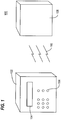
- FIG. 1 depicts an embodiment of an exemplary security keypad system 100 in accordance with aspects of this disclosure.
- Security keypad system 100 includes a wireless keypad 102 and a control panel 108.
- the wireless keypad 102 includes a liquid crystal display (“LCD”) (e.g., dual type information display) 104; and a user interface 106 (e.g., depicted as buttons for data input and/or response selection).
- LCD liquid crystal display
- user interface 106 e.g., depicted as buttons for data input and/or response selection.
- Lead-line 110 demarcates a wireless communication path between keypad 102 and control panel 108.
- a user is able to control a security system using the wireless keypad 102.
- the wireless keypad 102 is not in a fixed location or in proximity to a fixed location the user is prevented from accessing a feature on the wireless keypad (e.g., the user is prevented from arming the alarm system).
- the wireless keypad 102 is not secured to the keypad wall mount bracket 108, the user will not be able to access the feature associated with arming the security system.
- the material disclosed herein reduced the number of retry attempts of a wireless transmission in order to preserve battery life and obtain a more reliable wireless communication.
- a device e.g., wireless keypad 102 listens to determine whether there are transmissions in progress by some other wireless component in the system. If another component is transmitting at that particular moment in time then the device will delay its own transmission until the other component is finished (which typically takes about a few milliseconds).
- Figure 2 depicts an embodiment of an exemplary method 200 in accordance with aspects of this disclosure.
- Figure 4 depicts an exemplary application of the method 200 depicted in Figure 2 in accordance with aspects disclosed herein. Specifically, Figure 4 depicts an embodiment of a timeline 400 using the exemplary method depicted in Figure 2 .
- Figure 4 also includes a legend explaining aspects of the timeline 400. For easier understanding, a reader is encouraged to simultaneously view Figures 2 and 4 .
- the method 200 begins at step 202 and proceeds to step 204.
- the keypad 102 using antenna 1 402, listens for RF activity (see also keypad state 406 of Figure 4 ) from any other component (e.g., other keypad or sensor) (also referred to herein as "Listen Before Talk").
- the keypad 102 periodically interrogates the panel 108 for a system state update of the panel 108 (i.e., to determine if the panel has changed state).
- a timespan "t4" begins. After interrogation, the method 200 proceeds to step 206.
- the keypad 102 transmits a "Request_for_Update" message to the panel 108 using antenna 1.
- the transmission state of the keypad 102 is illustratively depicted in Figure 4 keypad state 408; and the transmission state of the panel 108 is depicted as panel state 410 (when the panel receives the "Request_for_Update” message).
- the method 200 proceeds to step 208.
- step 208 the keypad 102 immediately switches its receiver “ON” to receive a reply message from the panel 108.
- keypad state 414 in Figure 4 , depicts the state of the keypad 102.
- a timespan “t1” is initiated and begins a predetermined timespan for the keypad receiver to be turned “ON.”
- timespan t1 there is a latency 412, due to processing, in the panel 108.
- the panel 108 transmits a reply message on the same antenna (e.g., panel antenna 1 (not shown)) used when the keypad's "Request_for_Update” message was received.
- the state of the panel 108 during transmission of the reply message is panel state 418.
- the method 200 proceeds to step 210.
- step 210 when no reply from the panel 108 has been received at point A, the keypad 102 times-out and switches the keypad receiver "OFF."
- a timespan "t2" begins at about the same time as timespan t1 with a duration less than the duration of the reply message (i.e., when the keypad receiver is turned ON) and ends prior to an initiation of a subsequent timespan also having a duration of t1. Thereafter, the method 200 proceeds to step 212.
- the panel 108 transmits a reply multiple times (e.g., twice) using either antenna because the panel 108 doesn't know if the reply message was correctly received by the keypad 102.
- the keypad only needs to listen for a reply until the correct reply is received, and doesn't need to retransmit to the panel 108. As a result, power is saved at the keypad 102.
- Figure 400 illustratively depicts a failure to receive a reply for the first three occasions (414 at point A or B) and a success receiving a reply at the last occasion 416.
- the keypad receiver When a valid sync of the reply message has been detected (e.g. when message address of receiver and destination match), at point C, the keypad receiver is NOT switched OFF, but continues to receive the panel reply message.
- timeout t4 A practical value for timeout t4 is 4 seconds, which implies that the panel will be able to inform the keypad about changes in the system state 2 seconds late on the average.
- multiple keypads e.g., up 4 wireless keypads
- multiple I/O modules e.g., up to 4 wireless I/O modules
- wireless outdoor sirens and beacons will be constructed around the mentioned I/O modules, start of sounding and/or flashing will be 4 seconds late at the most.
- the panel 108 changes antenna regularly, but never during reception of a request and subsequent transmission of a reply.
- FIG. 3 depicts an embodiment of an exemplary method 300 for dynamic transmission power optimization in accordance with aspects of this disclosure. More specifically, in method 300 the control radio panel module 108 dynamically controls the transmission power level of keypad 102 and I/O module (not shown). As explained in greater detail below, the control radio panel module 108 returns a single bit in a reply message, indicating whether the keypad 102 should increase or decrease the transmission power level of a next transmission.
- the transmission power level is expressed in dBm.
- dBm is used and defined herein as an abbreviation for the power ratio in decibel (dB) of the measured power referenced to one milliwatt (mW).
- the method 300 begins at step 302 when the keypad 102 is turned “on” and proceeds to step 304.
- the method 300 queries whether this is the first transmission of the keypad 102.
- the keypad 102 When the keypad 102 is turned “on” the keypad transmits a communications signal towards the control panel radio module 108. If, at step 302, it is the first time that the keypad 102 has been turned “ON” then there are no previous transmissions.
- the keypad 102 (or some other component in the system) is turned ON there is no history as to how loud (i.e., how strong) the keypad 102 (or other component) should transmit. If this is the first transmission by the keypad 102 (or other component) then the query at step 304 is answered affirmatively and the method 300 proceeds to step 306.
- the transmission level is set to 0dBm (a factory setting). There is only one first transmission from power up. The transmission from power up will be transmitted at a level of 0dBm and messages transmitted at this transmission level may fail (it may not be loud enough for the control panel radio module 108 to pick up that message and send an acknowledgement). Because of the low transmission level, the keypad 102 will not get an acknowledgement from the control panel radio module 108 on first power up.
- the method 300 proceeds to and ends at step 322 where the transmission level is set for the next transmission.
- step 304 If however, the query at step 304 is answered negatively, the method 300 proceeds to step 308.
- the query at step 304 is answered negatively when the keypad 102 (or other system component) had been previously powered up (i.e., sent a transmission).
- the method 300 queries whether the signal transmitted (e.g., by the keypad 102) is a retry attempt. If the query is answered affirmatively, the method proceeds to step 316.
- step 316 the transmission level of the signal transmitted by the keypad 102 is increased to the maximum transmission level (illustratively the maximum transmission level is described and depicted as +12dBm) of the device 102. Thereafter the method 300 proceeds to and ends at step 322.
- the maximum transmission level is described and depicted as +12dBm
- step 308 If a negative determination is made at step 308 (i.e., that the transmission attempt is not a retry attempt), the method 300 proceeds to step 310.
- the method 300 queries whether the signal strength indication flag as received from the control panel radio module 108 in the previous reply message of the panel indicates that the power level of the transmission signal transmitted by the keypad 102 should be increased. If the query at step 310 is answered affirmatively, the method 300 proceeds to step 314. If however, the query at step 310 is answered negatively, the method 300 proceeds to step 312.
- step 314 the method 300 queries whether the transmission level of the keypad 102 is already at its maximum transmission level. For illustrative purposes only, step 314 is described and depicted as having a maximum value of +12dBm. If the keypad is already at its maximum transmission level then the query at step 314 is answered affirmatively and proceeds to step 322.
- step 320 the transmission level of the keypad 102 is given an incremental increase (e.g., an increase of about +0.5dBm). Thereafter, the method 300 proceeds to step 322.
- Step 312 queries whether the transmission level of the keypad 102 is at its minimum transmission level (e.g., -20dBm).
- the minimum transmission level of the keypad 102 is at its minimum transmission level (e.g., -20dBm).
- Illustratively Figure 3 depicts the minimum transmission level of the keypad 102 as -20dBm. However, that depiction is for illustrative purposes only and not intended in any way to limit the scope of the invention.
- step 312 If the query at step 312 is answered affirmatively then the transmission level cannot be reduced further. As such, upon an affirmative determination at step 312, the method 300 proceeds to step 322.
- step 312 If however, the query at step 312 is answered negatively then the transmission level of the keypad 102 is not at its minimum transmission level and can be lowered. As such, upon a negative determination at step 312, the method 300 proceeds to step 318.
- step 318 the transmission level of the keypad 102 is given an incremental decrease (e.g., an incremental decrease of about 0.5dBm). Thereafter, the method 300 proceeds to and ends at step 322.
- an incremental decrease e.g., an incremental decrease of about 0.5dBm.
- Figure 5 depicts a high level block diagram of an embodiment of a controller 500, as part of electronic circuitry, suitable for use in performing the methods and model disclosed above and depicted in Figures 2 , 3 , and 4 .
- the controller 500 of Figure 5 comprises a processor 506 as well as a memory 508 for storing control programs 510 and the like.
- the memory 508 can also store the transmission power level management module (as explained above in regarding Figure3 ) and/or messaging model module (as explained above regarding Figures 2 and 4 .
- the processor 506 cooperates with conventional support circuitry 404 such as power supplies, clock circuits, cache memory and the like as well as circuits that assist in executing the software routines stored in the memory 508.
- controller 500 also contains input-output circuitry 502 that forms an interface between the various functional elements communicating with the controller 500.
- controller 500 of Figure 5 is depicted as a general-purpose computer that is programmed to perform various control functions in accordance with the present invention, the invention can be implemented in hardware, for example, as an application specified integrated circuit (ASIC). As such, the process steps described herein are intended to be broadly interpreted as being equivalently performed by software, hardware, or a combination thereof.
- ASIC application specified integrated circuit
Landscapes
- Engineering & Computer Science (AREA)
- Computer Networks & Wireless Communication (AREA)
- Signal Processing (AREA)
- Mobile Radio Communication Systems (AREA)
- Input From Keyboards Or The Like (AREA)
- Circuits Of Receivers In General (AREA)
Claims (7)
- Procédé d'établissement d'une communication sans fil entre un premier dispositif et un second dispositif comprenant :l'écoute sur le premier dispositif pour une activité de fréquence radio (« RF ») sur un récepteur en utilisant une première antenne (402) ;la transmission depuis le premier dispositif d'une première instruction en utilisant la première antenne (402) lorsqu'aucune activité RF n'est détectée ;la commutation dudit récepteur sur « marche » après ladite transmission pour écouter une réponse du second dispositif ;la mise dudit récepteur sur « arrêt » lorsque ledit récepteur ne reçoit pas de réponse dans un premier intervalle de temps prédéterminé (t1) ;la commutation dudit récepteur sur « marche » à nouveau pour écouter ladite réponse ;si aucune réponse n'est reçue avant la fin d'une période d'expiration (t4), la transmission d'une seconde instruction sur une seconde antenne (404) et/ou l'utilisation d'un niveau de puissance de transmission différent ;la commutation du récepteur sur « marche » pour écouter une réponse dudit second dispositif à la seconde instruction ; etla commutation dudit récepteur sur « arrêt » lorsqu'aucune réponse n'est reçue en utilisant ladite seconde antenne (404) ou ledit niveau de puissance de transmission différent.
- Procédé selon la revendication 1, dans lequel ledit récepteur comprend un dispositif de sécurité et ladite instruction comprend une « demande de mise à jour ».
- Procédé selon la revendication 1 ou 2, comprenant en outre :la détermination du fait que le premier dispositif est placé ou non sur « marche » pendant une première période, tente un nouvel essai ou a déjà établi une communication avec le second dispositif ; etla transmission à un niveau de puissance dépendant du fait que la transmission est ou non une transmission pour la première fois, une transmission d'un nouvel essai ou une transmission après qu'une réponse a été reçue du second dispositif.
- Procédé selon la revendication 3, dans lequel un niveau de puissance initial est choisi si le premier dispositif envoie une transmission pour la première fois.
- Procédé selon la revendication 4, dans lequel un niveau de puissance maximal est choisi si le premier dispositif envoie une transmission d'un nouvel essai.
- Procédé selon la revendication 3, dans lequel le niveau de puissance est ajusté pour des transmissions après qu'une réponse a été reçue du second dispositif sur la base de données de force du signal reçu fournies par le second dispositif dans la réponse.
- Procédé selon la revendication 6, dans lequel l'ajustement du niveau de puissance comprend l'une parmi la réduction du niveau de puissance d'environ 5 décibels et l'augmentation du niveau de puissance d'environ 5 décibels.
Applications Claiming Priority (2)
| Application Number | Priority Date | Filing Date | Title |
|---|---|---|---|
| US97111307P | 2007-09-10 | 2007-09-10 | |
| US11/967,748 US7995985B2 (en) | 2007-09-10 | 2007-12-31 | Wireless security messaging model |
Publications (3)
| Publication Number | Publication Date |
|---|---|
| EP2034615A2 EP2034615A2 (fr) | 2009-03-11 |
| EP2034615A3 EP2034615A3 (fr) | 2014-07-30 |
| EP2034615B1 true EP2034615B1 (fr) | 2018-10-31 |
Family
ID=40101145
Family Applications (1)
| Application Number | Title | Priority Date | Filing Date |
|---|---|---|---|
| EP08164086.4A Active EP2034615B1 (fr) | 2007-09-10 | 2008-09-10 | Modèle de messagerie sans fil sécurisé |
Country Status (3)
| Country | Link |
|---|---|
| US (2) | US7995985B2 (fr) |
| EP (1) | EP2034615B1 (fr) |
| CN (1) | CN101409585B (fr) |
Families Citing this family (5)
| Publication number | Priority date | Publication date | Assignee | Title |
|---|---|---|---|---|
| US7995985B2 (en) | 2007-09-10 | 2011-08-09 | Utc Fire & Security Americas Corporation, Inc. | Wireless security messaging model |
| US8427986B2 (en) | 2008-06-13 | 2013-04-23 | Research In Motion Limited | Apparatus and method for transmitting messages in mobile telecommunications system user equipment |
| US9037180B2 (en) * | 2011-05-19 | 2015-05-19 | Qualcomm Incorporated | Measurements and information gathering in a wireless network environment |
| US9300147B2 (en) | 2011-06-29 | 2016-03-29 | Lg Electronics Inc. | Method for avoiding signal collision in wireless power transfer |
| US8774334B2 (en) * | 2011-11-09 | 2014-07-08 | Qualcomm Incorporated | Dynamic receiver switching |
Family Cites Families (10)
| Publication number | Priority date | Publication date | Assignee | Title |
|---|---|---|---|---|
| US7529547B2 (en) * | 2005-06-03 | 2009-05-05 | Terahop Networks, Inc. | Using wake-up receivers for soft hand-off in wireless communications |
| US6614393B2 (en) * | 2001-01-31 | 2003-09-02 | Hewlett-Packard Development Company, L.P. | Location data dissemination and reception for entities having short-range receivers |
| US7239884B2 (en) * | 2003-01-23 | 2007-07-03 | Motorola, Inc. | Method for providing improved access times for a communication device |
| EP3029872B1 (fr) * | 2003-02-03 | 2020-04-01 | Sony Corporation | Évitement de collisions dans des reseaux ad-hoc mobiles |
| US20060227729A1 (en) | 2005-04-12 | 2006-10-12 | Honeywell International Inc. | Wireless communication system with collision avoidance protocol |
| WO2006130272A2 (fr) * | 2005-04-26 | 2006-12-07 | Texas Instruments Incorporated | Procede et appareil de regulation de la puissance de transmission dans des systemes sans fil de communication de donnees |
| US8169938B2 (en) * | 2005-06-05 | 2012-05-01 | Starkey Laboratories, Inc. | Communication system for wireless audio devices |
| JP2007306201A (ja) * | 2006-05-10 | 2007-11-22 | Konica Minolta Holdings Inc | 情報端末装置および無線通信システム |
| US7920497B2 (en) * | 2007-08-15 | 2011-04-05 | Hitachi, Ltd. | System and method for multicast/broadcast reliability enhancement over wireless LANs |
| US7995985B2 (en) | 2007-09-10 | 2011-08-09 | Utc Fire & Security Americas Corporation, Inc. | Wireless security messaging model |
-
2007
- 2007-12-31 US US11/967,748 patent/US7995985B2/en active Active
-
2008
- 2008-09-10 EP EP08164086.4A patent/EP2034615B1/fr active Active
- 2008-09-10 CN CN200810173739.7A patent/CN101409585B/zh not_active Expired - Fee Related
-
2011
- 2011-07-25 US US13/136,146 patent/US8583074B2/en active Active
Non-Patent Citations (1)
| Title |
|---|
| None * |
Also Published As
| Publication number | Publication date |
|---|---|
| US7995985B2 (en) | 2011-08-09 |
| EP2034615A3 (fr) | 2014-07-30 |
| CN101409585A (zh) | 2009-04-15 |
| US20110287803A1 (en) | 2011-11-24 |
| CN101409585B (zh) | 2015-11-25 |
| US8583074B2 (en) | 2013-11-12 |
| EP2034615A2 (fr) | 2009-03-11 |
| US20090068977A1 (en) | 2009-03-12 |
Similar Documents
| Publication | Publication Date | Title |
|---|---|---|
| US6871078B2 (en) | Wireless communication device capable of controlling transmission power and transmission power control method therefor and wireless communication system employing the same | |
| US8005364B2 (en) | Method and apparatus for communicating in the presence of radio frequency energy | |
| US5152006A (en) | Receiver controller method and apparatus | |
| KR101136314B1 (ko) | 이동 통신 단말 및 이동 통신 단말에서의 송신 전력 제어 방법 | |
| US8583074B2 (en) | Wireless security messaging model | |
| US20080212508A1 (en) | Power saving method in wireless lan system for permitting terminal station to promptly transition to doze state by transmitting empty data frame | |
| US5355518A (en) | Receiver with constant battery saving duty cycle | |
| US20180124704A1 (en) | Method of Wake-up Signal Transmission and Reception | |
| KR20140066751A (ko) | 마스터 디바이스와 슬레이브 디바이스 사이의 무선 데이터 통신 | |
| CN102474817A (zh) | 休眠模式操作的更新方法和装置 | |
| US20100240319A1 (en) | Radio system, transmitter, and receiver | |
| JP2009514309A (ja) | 無線通信装置及び制御方法 | |
| US9572109B2 (en) | Reduced power consumption in a wireless network device | |
| JPH1098427A (ja) | 携帯移動無線端末装置 | |
| EP2219308B1 (fr) | Procédé et systèmes pour faciliter la réduction des interférences entre des signaux rf | |
| US7509150B1 (en) | Reducing power consumption in a radio device by early receiver shut down | |
| KR101976576B1 (ko) | 무선랜에서 절전 방법 및 장치 | |
| EP3716229A1 (fr) | Système et procédé de réduction d'une plage de communication | |
| JP2001094505A (ja) | 間欠受信方法 | |
| JP4261028B2 (ja) | 送受信装置及びこの送受信装置を用いたデータキャリアシステム | |
| EP1334574A1 (fr) | Procede et appareil de synchronisation de radios mobiles | |
| JP2678690B2 (ja) | 受信機コントローラの方法および装置 | |
| JP4679476B2 (ja) | 無線通信装置 | |
| EP4074104B1 (fr) | Procédé de transmission de données efficace en puissance | |
| JP2002232337A (ja) | 無線通信方法およびシステム |
Legal Events
| Date | Code | Title | Description |
|---|---|---|---|
| PUAI | Public reference made under article 153(3) epc to a published international application that has entered the european phase |
Free format text: ORIGINAL CODE: 0009012 |
|
| AK | Designated contracting states |
Kind code of ref document: A2 Designated state(s): AT BE BG CH CY CZ DE DK EE ES FI FR GB GR HR HU IE IS IT LI LT LU LV MC MT NL NO PL PT RO SE SI SK TR |
|
| AX | Request for extension of the european patent |
Extension state: AL BA MK RS |
|
| RAP1 | Party data changed (applicant data changed or rights of an application transferred) |
Owner name: UTC FIRE & SECURITY AMERICAS CORPORATION, INC. |
|
| RAP1 | Party data changed (applicant data changed or rights of an application transferred) |
Owner name: UTC FIRE & SECURITY AMERICAS CORPORATION, INC. |
|
| RIC1 | Information provided on ipc code assigned before grant |
Ipc: H04B 1/16 20060101AFI20140304BHEP |
|
| PUAL | Search report despatched |
Free format text: ORIGINAL CODE: 0009013 |
|
| AK | Designated contracting states |
Kind code of ref document: A3 Designated state(s): AT BE BG CH CY CZ DE DK EE ES FI FR GB GR HR HU IE IS IT LI LT LU LV MC MT NL NO PL PT RO SE SI SK TR |
|
| AX | Request for extension of the european patent |
Extension state: AL BA MK RS |
|
| RIC1 | Information provided on ipc code assigned before grant |
Ipc: H04B 1/16 20060101AFI20140620BHEP |
|
| 17P | Request for examination filed |
Effective date: 20150130 |
|
| RBV | Designated contracting states (corrected) |
Designated state(s): AT BE BG CH CY CZ DE DK EE ES FI FR GB GR HR HU IE IS IT LI LT LU LV MC MT NL NO PL PT RO SE SI SK TR |
|
| AKX | Designation fees paid |
Designated state(s): AT BE BG CH CY CZ DE DK EE ES FI FR GB GR HR HU IE IS IT LI LT LU LV MC MT NL NO PL PT RO SE SI SK TR |
|
| AXX | Extension fees paid |
Extension state: AL Extension state: BA Extension state: RS Extension state: MK |
|
| GRAP | Despatch of communication of intention to grant a patent |
Free format text: ORIGINAL CODE: EPIDOSNIGR1 |
|
| STAA | Information on the status of an ep patent application or granted ep patent |
Free format text: STATUS: GRANT OF PATENT IS INTENDED |
|
| INTG | Intention to grant announced |
Effective date: 20180323 |
|
| GRAS | Grant fee paid |
Free format text: ORIGINAL CODE: EPIDOSNIGR3 |
|
| GRAA | (expected) grant |
Free format text: ORIGINAL CODE: 0009210 |
|
| STAA | Information on the status of an ep patent application or granted ep patent |
Free format text: STATUS: THE PATENT HAS BEEN GRANTED |
|
| AK | Designated contracting states |
Kind code of ref document: B1 Designated state(s): AT BE BG CH CY CZ DE DK EE ES FI FR GB GR HR HU IE IS IT LI LT LU LV MC MT NL NO PL PT RO SE SI SK TR |
|
| REG | Reference to a national code |
Ref country code: GB Ref legal event code: FG4D Ref country code: CH Ref legal event code: EP |
|
| REG | Reference to a national code |
Ref country code: AT Ref legal event code: REF Ref document number: 1060628 Country of ref document: AT Kind code of ref document: T Effective date: 20181115 |
|
| REG | Reference to a national code |
Ref country code: DE Ref legal event code: R096 Ref document number: 602008057649 Country of ref document: DE |
|
| REG | Reference to a national code |
Ref country code: IE Ref legal event code: FG4D |
|
| REG | Reference to a national code |
Ref country code: NL Ref legal event code: FP |
|
| REG | Reference to a national code |
Ref country code: LT Ref legal event code: MG4D |
|
| REG | Reference to a national code |
Ref country code: AT Ref legal event code: MK05 Ref document number: 1060628 Country of ref document: AT Kind code of ref document: T Effective date: 20181031 |
|
| PG25 | Lapsed in a contracting state [announced via postgrant information from national office to epo] |
Ref country code: PL Free format text: LAPSE BECAUSE OF FAILURE TO SUBMIT A TRANSLATION OF THE DESCRIPTION OR TO PAY THE FEE WITHIN THE PRESCRIBED TIME-LIMIT Effective date: 20181031 Ref country code: BG Free format text: LAPSE BECAUSE OF FAILURE TO SUBMIT A TRANSLATION OF THE DESCRIPTION OR TO PAY THE FEE WITHIN THE PRESCRIBED TIME-LIMIT Effective date: 20190131 Ref country code: ES Free format text: LAPSE BECAUSE OF FAILURE TO SUBMIT A TRANSLATION OF THE DESCRIPTION OR TO PAY THE FEE WITHIN THE PRESCRIBED TIME-LIMIT Effective date: 20181031 Ref country code: LV Free format text: LAPSE BECAUSE OF FAILURE TO SUBMIT A TRANSLATION OF THE DESCRIPTION OR TO PAY THE FEE WITHIN THE PRESCRIBED TIME-LIMIT Effective date: 20181031 Ref country code: LT Free format text: LAPSE BECAUSE OF FAILURE TO SUBMIT A TRANSLATION OF THE DESCRIPTION OR TO PAY THE FEE WITHIN THE PRESCRIBED TIME-LIMIT Effective date: 20181031 Ref country code: HR Free format text: LAPSE BECAUSE OF FAILURE TO SUBMIT A TRANSLATION OF THE DESCRIPTION OR TO PAY THE FEE WITHIN THE PRESCRIBED TIME-LIMIT Effective date: 20181031 Ref country code: NO Free format text: LAPSE BECAUSE OF FAILURE TO SUBMIT A TRANSLATION OF THE DESCRIPTION OR TO PAY THE FEE WITHIN THE PRESCRIBED TIME-LIMIT Effective date: 20190131 Ref country code: AT Free format text: LAPSE BECAUSE OF FAILURE TO SUBMIT A TRANSLATION OF THE DESCRIPTION OR TO PAY THE FEE WITHIN THE PRESCRIBED TIME-LIMIT Effective date: 20181031 Ref country code: FI Free format text: LAPSE BECAUSE OF FAILURE TO SUBMIT A TRANSLATION OF THE DESCRIPTION OR TO PAY THE FEE WITHIN THE PRESCRIBED TIME-LIMIT Effective date: 20181031 Ref country code: IS Free format text: LAPSE BECAUSE OF FAILURE TO SUBMIT A TRANSLATION OF THE DESCRIPTION OR TO PAY THE FEE WITHIN THE PRESCRIBED TIME-LIMIT Effective date: 20190228 |
|
| PG25 | Lapsed in a contracting state [announced via postgrant information from national office to epo] |
Ref country code: PT Free format text: LAPSE BECAUSE OF FAILURE TO SUBMIT A TRANSLATION OF THE DESCRIPTION OR TO PAY THE FEE WITHIN THE PRESCRIBED TIME-LIMIT Effective date: 20190301 Ref country code: SE Free format text: LAPSE BECAUSE OF FAILURE TO SUBMIT A TRANSLATION OF THE DESCRIPTION OR TO PAY THE FEE WITHIN THE PRESCRIBED TIME-LIMIT Effective date: 20181031 Ref country code: GR Free format text: LAPSE BECAUSE OF FAILURE TO SUBMIT A TRANSLATION OF THE DESCRIPTION OR TO PAY THE FEE WITHIN THE PRESCRIBED TIME-LIMIT Effective date: 20190201 |
|
| PG25 | Lapsed in a contracting state [announced via postgrant information from national office to epo] |
Ref country code: IT Free format text: LAPSE BECAUSE OF FAILURE TO SUBMIT A TRANSLATION OF THE DESCRIPTION OR TO PAY THE FEE WITHIN THE PRESCRIBED TIME-LIMIT Effective date: 20181031 Ref country code: DK Free format text: LAPSE BECAUSE OF FAILURE TO SUBMIT A TRANSLATION OF THE DESCRIPTION OR TO PAY THE FEE WITHIN THE PRESCRIBED TIME-LIMIT Effective date: 20181031 Ref country code: CZ Free format text: LAPSE BECAUSE OF FAILURE TO SUBMIT A TRANSLATION OF THE DESCRIPTION OR TO PAY THE FEE WITHIN THE PRESCRIBED TIME-LIMIT Effective date: 20181031 |
|
| REG | Reference to a national code |
Ref country code: DE Ref legal event code: R097 Ref document number: 602008057649 Country of ref document: DE |
|
| PG25 | Lapsed in a contracting state [announced via postgrant information from national office to epo] |
Ref country code: EE Free format text: LAPSE BECAUSE OF FAILURE TO SUBMIT A TRANSLATION OF THE DESCRIPTION OR TO PAY THE FEE WITHIN THE PRESCRIBED TIME-LIMIT Effective date: 20181031 Ref country code: RO Free format text: LAPSE BECAUSE OF FAILURE TO SUBMIT A TRANSLATION OF THE DESCRIPTION OR TO PAY THE FEE WITHIN THE PRESCRIBED TIME-LIMIT Effective date: 20181031 Ref country code: SK Free format text: LAPSE BECAUSE OF FAILURE TO SUBMIT A TRANSLATION OF THE DESCRIPTION OR TO PAY THE FEE WITHIN THE PRESCRIBED TIME-LIMIT Effective date: 20181031 |
|
| PLBE | No opposition filed within time limit |
Free format text: ORIGINAL CODE: 0009261 |
|
| STAA | Information on the status of an ep patent application or granted ep patent |
Free format text: STATUS: NO OPPOSITION FILED WITHIN TIME LIMIT |
|
| 26N | No opposition filed |
Effective date: 20190801 |
|
| PG25 | Lapsed in a contracting state [announced via postgrant information from national office to epo] |
Ref country code: SI Free format text: LAPSE BECAUSE OF FAILURE TO SUBMIT A TRANSLATION OF THE DESCRIPTION OR TO PAY THE FEE WITHIN THE PRESCRIBED TIME-LIMIT Effective date: 20181031 |
|
| PG25 | Lapsed in a contracting state [announced via postgrant information from national office to epo] |
Ref country code: TR Free format text: LAPSE BECAUSE OF FAILURE TO SUBMIT A TRANSLATION OF THE DESCRIPTION OR TO PAY THE FEE WITHIN THE PRESCRIBED TIME-LIMIT Effective date: 20181031 |
|
| PG25 | Lapsed in a contracting state [announced via postgrant information from national office to epo] |
Ref country code: MC Free format text: LAPSE BECAUSE OF FAILURE TO SUBMIT A TRANSLATION OF THE DESCRIPTION OR TO PAY THE FEE WITHIN THE PRESCRIBED TIME-LIMIT Effective date: 20181031 |
|
| REG | Reference to a national code |
Ref country code: CH Ref legal event code: PL |
|
| PG25 | Lapsed in a contracting state [announced via postgrant information from national office to epo] |
Ref country code: LI Free format text: LAPSE BECAUSE OF NON-PAYMENT OF DUE FEES Effective date: 20190930 Ref country code: LU Free format text: LAPSE BECAUSE OF NON-PAYMENT OF DUE FEES Effective date: 20190910 Ref country code: IE Free format text: LAPSE BECAUSE OF NON-PAYMENT OF DUE FEES Effective date: 20190910 Ref country code: CH Free format text: LAPSE BECAUSE OF NON-PAYMENT OF DUE FEES Effective date: 20190930 |
|
| REG | Reference to a national code |
Ref country code: BE Ref legal event code: MM Effective date: 20190930 |
|
| PG25 | Lapsed in a contracting state [announced via postgrant information from national office to epo] |
Ref country code: BE Free format text: LAPSE BECAUSE OF NON-PAYMENT OF DUE FEES Effective date: 20190930 |
|
| GBPC | Gb: european patent ceased through non-payment of renewal fee |
Effective date: 20190910 |
|
| PG25 | Lapsed in a contracting state [announced via postgrant information from national office to epo] |
Ref country code: GB Free format text: LAPSE BECAUSE OF NON-PAYMENT OF DUE FEES Effective date: 20190910 |
|
| PG25 | Lapsed in a contracting state [announced via postgrant information from national office to epo] |
Ref country code: CY Free format text: LAPSE BECAUSE OF FAILURE TO SUBMIT A TRANSLATION OF THE DESCRIPTION OR TO PAY THE FEE WITHIN THE PRESCRIBED TIME-LIMIT Effective date: 20181031 |
|
| PG25 | Lapsed in a contracting state [announced via postgrant information from national office to epo] |
Ref country code: MT Free format text: LAPSE BECAUSE OF FAILURE TO SUBMIT A TRANSLATION OF THE DESCRIPTION OR TO PAY THE FEE WITHIN THE PRESCRIBED TIME-LIMIT Effective date: 20181031 Ref country code: HU Free format text: LAPSE BECAUSE OF FAILURE TO SUBMIT A TRANSLATION OF THE DESCRIPTION OR TO PAY THE FEE WITHIN THE PRESCRIBED TIME-LIMIT; INVALID AB INITIO Effective date: 20080910 |
|
| PGFP | Annual fee paid to national office [announced via postgrant information from national office to epo] |
Ref country code: NL Payment date: 20230822 Year of fee payment: 16 |
|
| PGFP | Annual fee paid to national office [announced via postgrant information from national office to epo] |
Ref country code: FR Payment date: 20230822 Year of fee payment: 16 Ref country code: DE Payment date: 20230822 Year of fee payment: 16 |