EP2032830B1 - Führungsträger für triebwerksverkleidungen - Google Patents
Führungsträger für triebwerksverkleidungen Download PDFInfo
- Publication number
- EP2032830B1 EP2032830B1 EP07718515A EP07718515A EP2032830B1 EP 2032830 B1 EP2032830 B1 EP 2032830B1 EP 07718515 A EP07718515 A EP 07718515A EP 07718515 A EP07718515 A EP 07718515A EP 2032830 B1 EP2032830 B1 EP 2032830B1
- Authority
- EP
- European Patent Office
- Prior art keywords
- track beam
- hollow section
- engine cowling
- fittings
- cowling
- Prior art date
- Legal status (The legal status is an assumption and is not a legal conclusion. Google has not performed a legal analysis and makes no representation as to the accuracy of the status listed.)
- Active
Links
Images


Classifications
-
- F—MECHANICAL ENGINEERING; LIGHTING; HEATING; WEAPONS; BLASTING
- F02—COMBUSTION ENGINES; HOT-GAS OR COMBUSTION-PRODUCT ENGINE PLANTS
- F02K—JET-PROPULSION PLANTS
- F02K1/00—Plants characterised by the form or arrangement of the jet pipe or nozzle; Jet pipes or nozzles peculiar thereto
- F02K1/54—Nozzles having means for reversing jet thrust
- F02K1/64—Reversing fan flow
-
- F—MECHANICAL ENGINEERING; LIGHTING; HEATING; WEAPONS; BLASTING
- F02—COMBUSTION ENGINES; HOT-GAS OR COMBUSTION-PRODUCT ENGINE PLANTS
- F02K—JET-PROPULSION PLANTS
- F02K1/00—Plants characterised by the form or arrangement of the jet pipe or nozzle; Jet pipes or nozzles peculiar thereto
- F02K1/54—Nozzles having means for reversing jet thrust
- F02K1/64—Reversing fan flow
- F02K1/70—Reversing fan flow using thrust reverser flaps or doors mounted on the fan housing
-
- F—MECHANICAL ENGINEERING; LIGHTING; HEATING; WEAPONS; BLASTING
- F02—COMBUSTION ENGINES; HOT-GAS OR COMBUSTION-PRODUCT ENGINE PLANTS
- F02K—JET-PROPULSION PLANTS
- F02K1/00—Plants characterised by the form or arrangement of the jet pipe or nozzle; Jet pipes or nozzles peculiar thereto
- F02K1/78—Other construction of jet pipes
- F02K1/80—Couplings or connections
-
- F—MECHANICAL ENGINEERING; LIGHTING; HEATING; WEAPONS; BLASTING
- F05—INDEXING SCHEMES RELATING TO ENGINES OR PUMPS IN VARIOUS SUBCLASSES OF CLASSES F01-F04
- F05D—INDEXING SCHEME FOR ASPECTS RELATING TO NON-POSITIVE-DISPLACEMENT MACHINES OR ENGINES, GAS-TURBINES OR JET-PROPULSION PLANTS
- F05D2300/00—Materials; Properties thereof
- F05D2300/20—Oxide or non-oxide ceramics
- F05D2300/22—Non-oxide ceramics
- F05D2300/224—Carbon, e.g. graphite
-
- F—MECHANICAL ENGINEERING; LIGHTING; HEATING; WEAPONS; BLASTING
- F05—INDEXING SCHEMES RELATING TO ENGINES OR PUMPS IN VARIOUS SUBCLASSES OF CLASSES F01-F04
- F05D—INDEXING SCHEME FOR ASPECTS RELATING TO NON-POSITIVE-DISPLACEMENT MACHINES OR ENGINES, GAS-TURBINES OR JET-PROPULSION PLANTS
- F05D2300/00—Materials; Properties thereof
- F05D2300/40—Organic materials
- F05D2300/44—Resins
-
- F—MECHANICAL ENGINEERING; LIGHTING; HEATING; WEAPONS; BLASTING
- F05—INDEXING SCHEMES RELATING TO ENGINES OR PUMPS IN VARIOUS SUBCLASSES OF CLASSES F01-F04
- F05D—INDEXING SCHEME FOR ASPECTS RELATING TO NON-POSITIVE-DISPLACEMENT MACHINES OR ENGINES, GAS-TURBINES OR JET-PROPULSION PLANTS
- F05D2300/00—Materials; Properties thereof
- F05D2300/60—Properties or characteristics given to material by treatment or manufacturing
- F05D2300/603—Composites; e.g. fibre-reinforced
-
- Y—GENERAL TAGGING OF NEW TECHNOLOGICAL DEVELOPMENTS; GENERAL TAGGING OF CROSS-SECTIONAL TECHNOLOGIES SPANNING OVER SEVERAL SECTIONS OF THE IPC; TECHNICAL SUBJECTS COVERED BY FORMER USPC CROSS-REFERENCE ART COLLECTIONS [XRACs] AND DIGESTS
- Y02—TECHNOLOGIES OR APPLICATIONS FOR MITIGATION OR ADAPTATION AGAINST CLIMATE CHANGE
- Y02T—CLIMATE CHANGE MITIGATION TECHNOLOGIES RELATED TO TRANSPORTATION
- Y02T50/00—Aeronautics or air transport
- Y02T50/60—Efficient propulsion technologies, e.g. for aircraft
Definitions
- the invention relates to a guide support for the lining of jet engines for aircraft, comprising a basic body formed by a hollow profile with a substantially closed cross-section with at least one slide for displaceably mounting a Schubumledge issued, with a connection for an inner engine cowling, and with fittings for releasable and pivotable Attachment to a supporting structure or for connection to another guide carrier.
- Modern jet engines as they are mainly used for propulsion of aircraft, have a so-called thrust reverser mechanism.
- the thrust reverser is necessary to decelerate the aircraft on the ground by generating thrust against the direction of travel.
- the thrust reverser mechanism usually includes a displaceably mounted part of the outer engine cowling, the so-called “Translating Sleeve”, on which the deflecting flaps, which ultimately serve to deflect the air flow, are arranged to be movable.
- the air diverted through the diverters is diverted through a gap in the engine cowling, which results between the rearwardly displaced portion of the outer cowl and the rest of the engine cowling.
- the airflow is forced through a gap formed between an outer and inner engine cowling, producing thrust.
- the essential parts of an engine cowling include an inner engine cowling disposed about the jet engine and an outer engine cowling and the longitudinally slidably-disposed portion of the outer engine cowling that forms the thrust reverser mechanism.
- the longitudinally displaceable part of the outer engine cowling slides on a total of four guide beams, which are connected to the inner engine cowling are.
- the inner lining of the engines consists of two substantially semi-cylindrical wall parts, which enclose the engine.
- the cowling of the engine must be made so stable that in the case of the explosion of an engine parts are not thrown outward, where they could damage further aircraft parts.
- the wall parts of the inner engine cowling are connected both at the top (in the 12 o'clock position) and at the bottom (in the 6 o'clock position) with one guide carrier each.
- the guide beams are usually made of metal, such as aluminum or titanium alloys, and are connected to the inner engine cowling by rivets and / or screws.
- the upper guide beams at the 12 o'clock position of the engine cowling, the so-called “hinge beams” are pivotally connected to a supporting structure, the so-called pylon, via corresponding hinges.
- the hinges are connected via corresponding fittings on the upper guide rails.
- the lower guide beams at the 6 o'clock position of the engine cowling, the so-called "latch beams” are fixedly connected to one another via corresponding connecting elements. To attach these fasteners are also on the lower guide rails appropriate fittings.
- Previous designs of the guide carrier are relatively expensive to manufacture and also have relatively high weight.
- the wall parts of the inner engine cowling are often made of plastic composite material.
- plastic composite material and metals have very different temperature coefficients, it comes with temperature fluctuations to different dimensions of the wall parts made of plastic composite material and the guide carrier made of metal.
- particularly high shear forces occur at the joint between the parts made of plastic composite material and the metal parts.
- the connections between plastic part and metal part must be oversized accordingly and provided a corresponding number of screws or rivets. Apart from the higher cost and the higher cost results from the higher number of fasteners and a higher Weight of the cowling.
- the EP 586 000 B1 shows, for example, a thrust reverser made of non-metallic carbon fiber reinforced composite material of higher thermal conductivity honeycomb. As a result, a lower weight of the thrust reverser is achieved with good heat dissipation. However, this document contains no information about the structures to which the thrust reverser is attached.
- the EP 540 193 A1 describes an inner engine cowling of the subject type, which is made of composite material with carbon fibers, wherein the wall parts of the engine cowling are made together with the flanges in one piece. The attachment of the panel to supporting structures is not described.
- the US 5 083 426 A describes an inner engine cowling, in which the wall parts surrounding the engine are also made in one piece from plastic composite material.
- the US 5 863 014 A shows a jet engine for aircraft with a thrust reverser mechanism, wherein the guide support is constructed in the form of a hollow profile.
- the EP 14 57 659 describes a guide carrier with the features of the preamble of claim 1.
- the object of the present invention is therefore to provide an above-mentioned guide support for an engine cowling, which has the lowest possible weight and reduces the disadvantages described above in terms of thermal expansion.
- the guide carrier should be as stiff as possible despite the low weight and the high loads withstand.
- the management carrier should be as easy to produce and have the best possible long-term properties.
- the object of the invention is achieved in that the hollow profile is made of carbon fiber reinforced plastic material according to the resin infusion method. Due to the structure of the main body of the guide carrier in the form of a hollow profile with a substantially closed cross-section, the required rigidity is achieved with thin wall thicknesses and thus low weight at the same time. Thus, unlike prior art guide beams, which are made of metal and include a series of stiffening ribs, no elaborate molds need to be used for manufacturing, resulting in easier manufacturability and lower manufacturing costs. The fact that the usually made of metal guide carrier is made of carbon fiber reinforced plastic material, thus the weight of the engine cowling can be reduced and also the problem of different thermal expansion and thus the occurring shear forces between the guide bracket and inner engine cowling are largely reduced.
- the formation of complex three-dimensional components with special properties is possible.
- the resin infusion method offers advantages over conventional manufacturing methods using an autoclave in which the prepreg material is cured. Also, the parts can be made cheaper than forged and milled parts of aluminum and titanium alloys.
- the guide carrier is made essentially of the same material as the inner engine cowling. As a result, both the guide carrier and the inner engine cowling have the same thermal expansion and there are no or no significant shear forces at the connection between the guide carrier and the inner engine cowling. As a result, the fasteners can be reduced and thus saved weight.
- the hollow profile may comprise stiffening structures, in particular stiffening ribs. These stiffening structures give the guide support a higher rigidity and low weight. Of course, by the stiffening structures of the mold work in the production increased after the resin infusion method.
- the hollow profile is made of carbon fiber reinforced plastic material according to the Resin Transfer Molding (RTM) method.
- RTM Resin Transfer Molding
- Parts of the hollow profile may be prefabricated from carbon fabric and incorporated in the production of the entire hollow profile made of carbon fiber reinforced plastic material according to the resin infusion, in particular RTM method.
- the resin infusion in particular RTM method.
- complex parts of the guide carrier can be prefabricated in simpler forms and then used in the production of the resin infusion process.
- Carbon fibers have advantages in terms of weight and strength properties.
- the fittings of the guide carrier can be integrated in the hollow profile of the body and made in one piece with this. Although this increases the mold cost in the production of the hollow profile of the body, but connections between the fittings and the hollow profile of the body are avoided.
- the fittings can also be made of carbon fiber reinforced plastic material according to the resin infusion, especially RTM method and then connected to the finished hollow profile, in particular glued, be.
- RTM method carbon fiber reinforced plastic material
- the mold cost is reduced in the resin infusion production. But it is a bonding between the parts required.
- fittings can be made in a conventional manner of metal and connected to the hollow profile, in particular glued, be.
- the carbon fabric used may be woven with nylon, and after addition of the resin, the nylon material may be dissolved, thereby increasing the impact resistance.
- the hollow profile has at least two flanges for forming the connection for the inner engine cowling, wherein the end of the inner engine cowling between the flanges can be inserted.
- the flanges provide optimal introduction of forces into the inner cowl achieved, whereby fewer connecting elements for connecting the inner engine cowling with the hollow profile are necessary.
- the inner engine cowling is glued to the hollow profile.
- metal fasteners fall away or their number can be reduced, which in turn results in a reduction in the overall weight of the engine cowling.
- the flanges may also have at least one bore for receiving a connecting element, for example a bolt, a screw or the like.
- a connecting element for example a bolt, a screw or the like.
- the hollow profile preferably has grooves for the formation of the sliding device for the displaceable mounting of the thrust reverser. These grooves can be made in the production of the hollow profile by the resin infusion method or produced in a separate step of carbon fabric and then integrated into the manufacturing process of the hollow section.
- the grooves have a circular sector-shaped cross-section. In these circular sector-shaped grooves slide on the thrust reverser or the displaceable in the longitudinal direction of the engine part of the outer engine cowling sliding elements in an optimal manner.
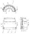
- the Fig. 1a to 1c show different views of the rear part of the panel 1 of jet engines for aircraft. How out Fig. 1c it can be seen, only half of the panel 1 is shown for the sake of clarity.
- the entire rear panel 1 of the jet engine consists of two such mirror-inverted parts of the panel 1.
- the thrust reverser 2 consists essentially of an outer engine cowling 3, the so-called “translating sleeve", which is slidably mounted in the longitudinal direction of the engine.
- the deflecting flaps 4 On the displaceable part of the outer engine cowling 3 are the deflecting flaps 4, which block the flow of air through the gap between the outer engine cowl 3 and the inner cowl 5 when the thrust reverser 2 is activated.
- the displaceable part of the outer engine cowling 3 slides on respective guide beams 6, 7, which are connected to the inner engine cowling 5.
- guide carriers 6 are arranged at the 12 o'clock position of the engine cowling 1 and guide carrier 7 at the 6 o'clock position of the engine cowling 1.
- the guide beams 6, 7 each consist of a base body 8, 9 and in each case at least one slide 10, 11, on which the Schubumledge coupled 2 is slidably mounted.
- the sliding devices 10, 11 consist of a groove, for example with Vietnamesesektorförmigem cross-section in which a corresponding complementary shaped element which is attached to the thrust reverser, in the longitudinal direction of the engine cowling 1 can be slidably mounted (not shown).
- the guide supports 6, 7 corresponding fittings 12, 13 for attachment to a support structure or for connection to another guide support 7.
- the upper guide support 6 via corresponding hinges (not shown), which with the fittings 12th be connected to a support structure, the so-called pylon, releasably and pivotally attached.
- the lower guide beams 7, however, are by connecting the fittings 13 (see Fig. 5 and 6 ) fixed with corresponding connecting elements, so that an accidental opening of the engine cowling 1 can not occur.
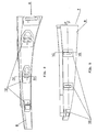
- the guide supports 6, 7 according to the invention are described in detail in FIGS Fig. 3 to 6 shown.
- the base body 8 is formed according to the invention by a hollow section 14 with a substantially closed cross-section.
- the base body 9 of the lower guide support 7 is formed by a hollow profile 15 with a substantially closed cross-section.
- the hollow profile 14, 15 of the base body 8, 9 of the guide beams 6, 7 made of carbon fiber reinforced plastic material according to the resin infusion, in particular RTM method. Due to the design of the guide support 6, 7 according to the invention by a hollow profile 14, 15 existing in conventional guide carriers made of metal innumerable stiffening ribs can be omitted, which is why the mold cost for the preparation of the resin infusion process is relatively low.
- the hollow profile 14, 15 gives the guide beams 6, 7 the required rigidity. Parts of the hollow profile 14, 15 can be prefabricated from carbon fabric and incorporated into the manufacturing process of the hollow section 14, 15.
- the parts 16, 17, which form the sliders 10, 11 are prefabricated from carbon fabric and are inserted in the production of the hollow sections 14, 15 by the resin infusion method in the mold.
- the fittings 12, 13 can in Hollow profile 14, 15 be integrated and manufactured in one piece with this.
- the fittings 12, 13 are made of carbon fiber reinforced plastic material by the resin infusion method and subsequently connected to the hollow section 14, 15, in particular glued, be. It is also possible that the fittings 12, 13 are made of metal and connected to the hollow section 14, 15, in particular glued, but also screwed or riveted, are.
- the hollow profile 14 and 15 respectively two flanges 18 and 19 to form the connection for the inner engine cowling 5.
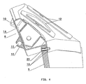
- FIG. 4 the connection of the inner engine cowling 5 on the hollow section 14 of the upper guide support 6 is shown.
- the inner engine cowling 5 with the hollow section 14, 15 are glued or via corresponding connecting elements 20, which are inserted through corresponding holes in the flanges 18, 19 take place. It is advantageous to use as few connecting elements 20 in order to carry out an exchange of the inner engine cowling 5 as quickly as possible.
Landscapes
- Engineering & Computer Science (AREA)
- Chemical & Material Sciences (AREA)
- Combustion & Propulsion (AREA)
- Mechanical Engineering (AREA)
- General Engineering & Computer Science (AREA)
- Moulding By Coating Moulds (AREA)
- Sliding-Contact Bearings (AREA)
- Bearings For Parts Moving Linearly (AREA)
- Cylinder Crankcases Of Internal Combustion Engines (AREA)
- Sawing (AREA)
- Telephone Function (AREA)
- Devices For Conveying Motion By Means Of Endless Flexible Members (AREA)
- Laminated Bodies (AREA)
Description
- Die Erfindung betrifft einen Führungsträger für die Verkleidung von Strahltriebwerken für Flugzeuge, umfassend einen durch ein Hohlprofil mit im Wesentlichen geschlossenem Querschnitt gebildeten Grundkörper mit zumindest einer Gleiteinrichtung zur verschieblichen Lagerung einer Schubumkehreinrichtung, mit einer Anbindung für eine innere Triebwerksverkleidung, und mit Beschlägen zur lösbaren und schwenkbaren Befestigung an einer Tragkonstruktion oder zur Verbindung mit einem anderen Führungsträger.
- Moderne Strahltriebwerke, wie sie hauptsächlich für den Antrieb von Flugzeugen eingesetzt werden, weisen einen so genannten Schubumkehrmechanismus auf. Die Schubumkehr ist zum Abbremsen des Flugzeugs am Boden durch Erzeugung von Schub entgegen der Bewegungsrichtung notwendig. Üblicherweise wird bei Strahltriebwerken durch geeignete Klappen (die so genannten "Blocker Doors") der Triebwerksstrahl nach vorne umgelenkt, wodurch dieser ein Bremsen des Flugzeugs bewirkt. Dadurch wird die Strecke, welche das Flugzeug zum Landen benötigt, verkürzt. Der Schubumkehrmechanismus enthält üblicherweise einen verschieblich gelagerten Teil der äußeren Triebwerksverkleidung, die so genannten "Translating Sleeve", an der die Umlenkklappen, welche schlussendlich zur Umlenkung des Luftstroms dienen, beweglich angeordnet sind. Die über die Umlenkklappen umgelenkte Luft wird durch einen Spalt in der Triebwerksverkleidung, welche sich zwischen dem nach hinten verschobenen Teil der äußeren Triebwerksverkleidung und der übrigen Triebwerksverkleidung ergibt, umgelenkt. Im normalen Betrieb des Triebwerks wird der Luftstrom durch einen zwischen einer äußeren und inneren Triebwerksverkleidung gebildeten Spalt gepresst, wodurch der Schub erzeugt wird.
- Die wesentlichen Teile einer Triebwerksverkleidung umfassen eine innere Triebwerksverkleidung, welche um das Strahltriebwerk angeordnet ist und eine äußere Triebwerksverkleidung sowie den in Längsrichtung verschieblich angeordneten Teil der äußeren Triebwerksverkleidung, der den Schubumkehrmechanismus bildet. Der in Längsrichtung des Triebwerks verschiebliche Teil der äußeren Triebwerksverkleidung gleitet auf insgesamt vier Führungsträgern, welche mit der inneren Triebwerksverkleidung verbunden sind. Die innere Verkleidung der Triebwerke besteht aus zwei im Wesentlichen halbzylinderförmigen Wandteilen, welche das Triebwerk umschließen. Die Verkleidung des Triebwerks muss so stabil ausgebildet sein, dass im Fall der Explosion eines Triebwerks Teile nicht nach außen geschleudert werden, wo sie weitere Flugzeugteile beschädigen könnten. Die Wandteile der inneren Triebwerksverkleidung sind sowohl oben (in der 12-Uhr-Position) als auch unten (in der 6-Uhr-Position) mit jeweils einem Führungsträger verbunden. Die Führungsträger bestehen üblicherweise aus Metall, wie beispielsweise Aluminium- oder Titanlegierungen und werden mit der inneren Triebwerksverkleidung durch Nieten und bzw. oder Schrauben verbunden. Die oberen Führungsträger an der 12-Uhr-Position der Triebwerksverkleidung, die so genannten "hinge beams", sind verschwenkbar mit einer Tragkonstruktion, dem so genannten Pylon, über entsprechende Scharniere verbunden. Die Scharniere werden über entsprechende Beschläge an den oberen Führungsträgern verbunden. Die unteren Führungsträger an der 6-Uhr-Position der Triebwerksverkleidung, die so genannten "latch beams", werden über entsprechende Verbindungselemente miteinander fix verbunden. Zur Befestigung dieser Verbindungselemente befinden sich an den unteren Führungsträgern ebenfalls entsprechende Beschläge.
- Bisherige Konstruktionen der Führungsträger sind relativ teuer in der Herstellung und weisen darüber hinaus relativ hohes Gewicht auf. Zur Reduktion des Gewichts werden die Wandteile der inneren Triebwerksverkleidung häufig aus Kunststoffverbundwerkstoff hergestellt. Im Bereich der Triebwerke treten enorm hohe Temperaturen auf, welchen insbesondere die Teile der inneren Triebwerksverkleidung ausgesetzt sind. Da Kunststoffverbundwerkstoff und Metalle sehr unterschiedliche Temperaturkoeffizienten aufweisen, kommt es bei Temperaturschwankungen zu unterschiedlichen Ausdehnungen der Wandteile aus Kunststoffverbundwerkstoff und der Führungsträger aus Metall. Dadurch treten insbesondere an der Verbindungsstelle zwischen den Teilen aus Kunststoffverbundwerkstoff und den Metallteilen besonders hohe Scherkräfte auf. Als Folge dessen müssen die Verbindungen zwischen Kunststoffteil und Metallteil entsprechend überdimensioniert werden und entsprechend viele Schrauben oder Nieten vorgesehen werden. Abgesehen vom höheren Aufwand und den höheren Kosten resultiert durch die höhere Anzahl von Verbindungselementen auch ein höheres Gewicht der Triebwerksverkleidung.
- Die
EP 586 000 B1 - Die
EP 540 193 A1 - Die
US 5 083 426 A beschreibt eine innere Triebwerksverkleidung, bei der die Wandteile, welche das Triebwerk umgeben, ebenfalls einstückig aus Kunststoffverbundwerkstoff hergestellt sind. - Die
US 6 584 763 B2 beschreibt eine Triebwerksverkleidung mit einem Schubumkehrmechanismus, wobei über die Beschaffenheit der Führungsträger und deren Verbindung mit der inneren Triebwerksverkleidung keine Information enthalten ist. - Die
US 5 863 014 A zeigt ein Strahltriebwerk für Flugzeuge mit einem Schubumkehrmechanismus, wobei der Führungsträger in Form eines Hohlprofils aufgebaut ist. - Die
EP 14 57 659 beschreibt einen Führungsträger mit den Merkmalen der Präambel des Anspruchs 1. - Es gab bereits Bestrebungen, zur Reduktion des Gewichts auch die Führungsträger der Triebwerksverkleidung aus faserverstärktem Kunststoffmaterial herzustellen. Aufgrund der hohen erforderlichen Steifigkeit dieser Bauteile war man jedoch gezwungen, besonders aufwändige Konstruktionen mit einer Vielzahl an Versteifungsstrukturen herzustellen, was mit einem besonders hohen Herstellungsaufwand, aber auch mit einem relativ hohen Gewicht verbunden war.
- Die Aufgabe der vorliegenden Erfindung besteht daher in der Schaffung eines oben genannten Führungsträgers für eine Triebwerksverkleidung, welcher möglichst geringes Gewicht aufweist und die oben beschriebenen Nachteile in Bezug auf die Wärmeausdehnung reduziert. Der Führungsträger soll trotz niedrigem Gewicht möglichst steif sein und den hohen Belastungen standhalten. Weiters soll der Führungsträger möglichst einfach herstellbar sein und möglichst gute Langzeiteigenschaften aufweisen.
- Gelöst wird die erfindungsgemäße Aufgabe dadurch, dass das Hohlprofil aus kohlenstofffaserverstärktem Kunststoffmaterial nach der Harz Infusions-Methode hergestellt ist. Durch den Aufbau des Grundkörpers des Führungsträgers in Form eines Hohlprofils mit im Wesentlichen geschlossenem Querschnitt wird die erforderliche Steifigkeit bei gleichzeitig dünnen Wandstärken und somit niedrigem Gewicht erzielt. Somit müssen, im Gegensatz zu Führungsträgern des Standes der Technik, welche aus Metall hergestellt sind und eine Reihe von Versteifungsrippen enthalten, keine aufwändigen Formen zur Herstellung verwendet werden, resultierend in einer einfacheren Herstellbarkeit und niedrigeren Herstellungskosten. Dadurch, dass auch der üblicherweise aus Metall hergestellte Führungsträger aus kohlenstofffaserverstärktem Kunststoffmaterial hergestellt wird, kann somit das Gewicht der Triebwerksverkleidung reduziert werden und auch das Problem der unterschiedlichen Wärmeausdehnung und somit der auftretenden Scherkräfte zwischen Führungsträger und innerer Triebwerksverkleidung weitestgehend reduziert werden. Durch ein Harz Infusions-Herstellungsverfahren ist die Bildung komplizierter dreidimensionaler Bauteile mit speziellen Eigenschaften möglich. Die Harz Infusions-Methode bringt gegenüber herkömmlichen Herstellungsmethoden unter Verwendung eines Autoklaven, in dem das Prepreg-Material ausgehärtet wird, Vorteile. Auch können die Teile gegenüber geschmiedeten und gefrästen Teilen aus Aluminium- und Titanlegierungen billiger hergestellt werden. Vorteilhafterweise wird der Führungsträger im Wesentlichen aus dem selben Material wie die innere Triebwerksverkleidung hergestellt. Dadurch weisen sowohl der Führungsträger als auch die innere Triebwerksverkleidung gleiche Wärmeausdehnung auf und es kommt zu keinen bzw. keinen wesentlichen Scherkräften an der Verbindung zwischen Führungsträger und innerer Triebwerksverkleidung. In der Folge können die Verbindungselemente reduziert und somit Gewicht eingespart werden. Das Hohlprofil kann Versteifungsstrukturen, insbesondere Versteifungsrippen, umfassen. Diese Versteifungsstrukturen geben dem Führungsträger eine höhere Steifigkeit bei gleichzeitig geringem Gewicht. Natürlich wird durch die Versteifungsstrukturen der Formenaufwand bei der Fertigung nach der Harz Infusions-Methode erhöht.
- Vorteilhafterweise ist das Hohlprofil aus kohlenstofffaserverstärktem Kunststoffmaterial nach der Resin Transfer Moulding (RTM)-Methode hergestellt.
- Teile des Hohlprofils können aus Carbongewebe vorgefertigt sein und bei der Herstellung des gesamten Hohlprofils aus kohlenstofffaserverstärktem Kunststoffmaterial nach der Harz Infusions-, insbesondere RTM-Methode eingebaut werden. Dadurch können komplexe Teile des Führungsträgers in einfacheren Formen vorgefertigt und dann bei der Herstellung nach dem Harz Infusions-Verfahren verwendet werden. Kohlenstofffasern haben hinsichtlich Gewicht und Festigkeitseigenschaften Vorteile.
- Die Beschläge der Führungsträger können im Hohlprofil des Grundkörpers integriert und mit diesem einstückig hergestellt sein. Dies erhöht zwar den Formenaufwand bei der Herstellung des Hohlprofils des Grundkörpers, es werden jedoch Verbindungen zwischen den Beschlägen und dem Hohlprofil des Grundkörpers vermieden.
- Alternativ dazu können die Beschläge auch aus kohlenstofffaserverstärktem Kunststoffmaterial nach der Harz Infusions-, insbesondere RTM-Methode hergestellt sein und anschließend mit dem fertigen Hohlprofil verbunden, insbesondere verklebt, werden. Durch diese Maßnahmen wird der Formenaufwand bei der Harz Infusions-Herstellung reduziert. Es wird aber eine Verklebung zwischen den Teilen erforderlich.
- Schließlich können die Beschläge auch in herkömmlicher Weise aus Metall hergestellt werden und mit dem Hohlprofil verbunden, insbesondere verklebt, werden.
- Wenn im Carbongewebe reaktive Materialien, wie z.B. Nylon, eingenäht oder eingewebt werden, können bestimmte Eigenschaften, wie Festigkeit oder Schlagzähigkeit, erhöht werden. Beispielsweise kann das verwendete Carbongewebe mit Nylon verwebt werden und nach Zugabe des Harzes das Nylonmaterial aufgelöst werden, wodurch die Schlagzähigkeit erhöht wird.
- Zur optimalen Verbindung der Führungsträger mit der inneren Triebwerksverkleidung weist das Hohlprofil zumindest zwei Flansche zur Bildung der Anbindung für die innere Triebwerksverkleidung auf, wobei das Ende der inneren Triebwerksverkleidung zwischen den Flanschen einsteckbar ist. Durch die Flansche wird eine optimale Einleitung der Kräfte in die innere Triebwerksverkleidung erzielt, wodurch weniger Verbindungselemente zur Verbindung der inneren Triebwerksverkleidung mit dem Hohlprofil notwendig sind.
- Gemäß einem weiteren Merkmal der Erfindung ist die innere Triebwerksverkleidung mit dem Hohlprofil verklebt. Durch die Verklebung fallen Verbindungselemente aus Metall weg bzw. kann deren Anzahl reduziert werden, was wiederum in einer Reduktion des Gesamtgewichts der Triebwerksverkleidung resultiert.
- Alternativ oder zusätzlich dazu können die Flansche auch zumindest eine Bohrung zur Aufnahme eines Verbindungselements, beispielsweise eines Bolzens, einer Schraube oder dergl. aufweisen. Dabei wird angestrebt, möglichst wenige Verbindungselemente zu verwenden, so dass ein Wechsel der inneren Triebwerksverkleidung rascher durchgeführt werden kann. Die Verwendung von Verbindungselementen im Gegensatz zu einer Klebeverbindung hat natürlich auch den Vorteil, dass eine Wartung bzw. ein Ersatz der durch thermische Belastung schneller alternden inneren Triebwerksverkleidung leicht bzw. überhaupt möglich ist.
- Im Falle einer Klebeverbindung können zusätzliche Deckschichten aus faserverstärktem Kunststoffmaterial mit der inneren Triebwerksverkleidung und dem Hohlprofil verklebt sein.
- Das Hohlprofil weist vorzugsweise Nuten zur Bildung der Gleiteinrichtung zur verschieblichen Lagerung der Schubumkehreinrichtung auf. Diese Nuten können bei der Herstellung des Hohlprofils nach der Harz Infusions-Methode angefertigt werden oder auch in einem eigenen Arbeitsschritt aus Carbongewebe hergestellt und danach in den Herstellungsvorgang des Hohlprofils integriert werden.
- Gemäß einem weiteren Merkmal der Erfindung weisen die Nuten kreissektorförmigen Querschnitt auf. In diesen kreissektorförmigen Nuten gleiten die an der Schubumkehreinrichtung bzw. dem in Längsrichtung des Triebwerks verschieblichen Teil der äußeren Triebwerksverkleidung angebrachten Gleitelemente in optimaler Weise.
- Die Erfindung wird anhand der beigefügten Zeichnungen noch weiter erläutert. Darin zeigen:
-
Fig. 1a die Seitenansicht auf den hinteren Teil einer Verkleidung eines Strahltriebwerks; -
Fig. 1b die Triebwerksverkleidung gemäßFig. 1a in Draufsicht; -
Fig. 1c die Triebwerksverkleidung gemäßFig. 1a in der Ansicht von vorne; - die
Fig. 2a bis 2c den Teil der Triebwerksverkleidung gemäß denFig. 1a bis 1c , ohne den Teil der äußeren Triebwerksverkleidung, der den Schubumkehrmechanismus bildet; -
Fig. 3 eine erfindungsgemäße Ausbildung eines oberen Führungsträgers; -
Fig. 4 ein Schnittbild durch den oberen Führungsträger gemäßFig. 3 entlang der Schnittlinie IV-IV; -
Fig. 5 eine erfindungsgemäße Ausbildung eines unteren Führungsträgers; und -
Fig. 6 ein Schnittbild durch den unteren Führungsträger gemäßFig. 5 entlang der Schnittlinie VI-VI. - Die
Fig. 1a bis 1c zeigen verschiedene Ansichten des hinteren Teils der Verkleidung 1 von Strahltriebwerken für Flugzeuge. Wie ausFig. 1c ersichtlich, ist der besseren Übersicht halber nur eine Hälfte der Verkleidung 1 dargestellt. Die gesamte hintere Verkleidung 1 des Strahltriebwerks besteht aus zwei derartigen spiegelbildlich zueinander angeordneten Teilen der Verkleidung 1. Die Schubumkehreinrichtung 2 besteht im Wesentlichen aus einer äußeren Triebwerksverkleidung 3, der so genannten "translating sleeve", welche in Längsrichtung des Triebwerks verschieblich gelagert ist. An dem verschieblichen Teil der äußeren Triebwerksverkleidung 3 befinden sich die Umlenkklappen 4, welche den Luftstrom durch den Spalt zwischen äußerer Triebwerksverkleidung 3 und innerer Triebwerksverkleidung 5 blockieren, wenn die Schubumkehreinrichtung 2 aktiviert ist. Der verschiebliche Teil der äußeren Triebwerksverkleidung 3 gleitet auf entsprechenden Führungsträgern 6, 7, welche mit der inneren Triebwerksverkleidung 5 verbunden sind. Dabei sind Führungsträger 6 an der 12-Uhr-Position der Triebwerksverkleidung 1 und Führungsträger 7 an der 6-Uhr-Position der Triebwerksverkleidung 1 angeordnet. - Wie besser aus den
Fig. 2a bis 2c , bei welchen die äußere Triebwerksverkleidung 3 der Schubumkehreinrichtung 2 gegenüber denFig. 1a bis 1c entfernt wurde, ersichtlich, bestehen die Führungsträger 6, 7 jeweils aus einem Grundkörper 8, 9 und jeweils zumindest einer Gleiteinrichtung 10, 11, auf welcher die Schubumkehreinrichtung 2 verschieblich gelagert ist. Die Gleiteinrichtungen 10, 11 bestehen aus einer Nut, beispielsweise mit kreissektorförmigem Querschnitt, in welcher ein entsprechend komplementär gestaltetes Element, welches an der Schubumkehreinrichtung befestigt ist, in Längsrichtung der Triebwerksverkleidung 1 verschiebbar gelagert werden kann (nicht dargestellt). Weiters enthalten die Führungsträger 6, 7 entsprechende Beschläge 12, 13 zur Befestigung an einer Tragkonstruktion oder zur Verbindung mit einem anderen Führungsträger 7. Zum Zwecke der Wartung des Triebwerks werden die oberen Führungsträger 6 über entsprechende Scharniere (nicht dargestellt), welche mit den Beschlägen 12 verbunden werden, an einer Tragkonstruktion, dem so genannten Pylon, lösbar und schwenkbar befestigt. Die unteren Führungsträger 7 hingegen werden durch Verbindung der Beschläge 13 (sieheFig. 5 und6 ) mit entsprechenden Verbindungselementen fixiert, so dass ein ungewolltes Öffnen der Triebwerksverkleidung 1 nicht auftreten kann. - Die erfindungsgemäßen Führungsträger 6, 7 sind im Detail in den
Fig. 3 bis 6 dargestellt. - In
Fig. 3 und dem Schnittbild gemäßFig. 4 ist ein oberer Führungsträger 6 gezeigt, dessen Grundkörper 8 erfindungsgemäß durch ein Hohlprofil 14 mit im Wesentlichen geschlossenem Querschnitt gebildet ist. - Ebenso ist gemäß
Fig. 5 und6 der Grundkörper 9 des unteren Führungsträgers 7 durch ein Hohlprofil 15 mit im Wesentlichen geschlossenem Querschnitt gebildet. - Erfindungsgemäß wird das Hohlprofil 14, 15 der Grundkörper 8, 9 der Führungsträger 6, 7 aus kohlenstofffaserverstärktem Kunststoffmaterial nach der Harz Infusions-, insbesondere RTM-Methode hergestellt. Aufgrund der erfindungsgemäßen Gestaltung der Führungsträger 6, 7 durch ein Hohlprofil 14, 15 können die bei üblichen Führungsträgern aus Metall vorhandenen unzähligen Versteifungsrippen entfallen, weshalb der Formenaufwand für die Herstellung nach dem Harz Infusions-Verfahren relativ gering ist. Das Hohlprofil 14, 15 verleiht den Führungsträgern 6, 7 die erforderliche Steifigkeit. Teile des Hohlprofils 14, 15 können aus Carbongewebe vorgefertigt werden und in das Herstellungsverfahren des Hohlprofils 14, 15 eingebunden werden. Beispielsweise können die Teile 16, 17, welche die Gleiteinrichtungen 10, 11 bilden, aus Carbongewebe vorgefertigt werden und bei der Herstellung der Hohlprofile 14, 15 nach der Harz Infusions-Methode in die Form eingelegt werden. Die Beschläge 12, 13 können im Hohlprofil 14, 15 integriert sein und mit diesem einstückig hergestellt werden. Ebenso können die Beschläge 12, 13 aus kohlenstofffaserverstärktem Kunststoffmaterial nach der Harz Infusions-Methode hergestellt werden und nachträglich mit dem Hohlprofil 14, 15 verbunden, insbesondere verklebt, werden. Ebenso ist es möglich, dass die Beschläge 12, 13 aus Metall hergestellt werden und mit dem Hohlprofil 14, 15 verbunden, insbesondere verklebt, aber auch verschraubt oder vernietet, werden.
- Zur optimalen Verbindung der Führungsträger 6, 7 mit der inneren Triebwerksverkleidung 5 weist das Hohlprofil 14 bzw. 15 jeweils zwei Flansche 18 bzw. 19 zur Bildung der Anbindung für die innere Triebwerksverkleidung 5 auf. In
Fig. 4 ist die Anbindung der inneren Triebwerksverkleidung 5 am Hohlprofil 14 des oberen Führungsträgers 6 dargestellt. Durch diese Verbindung über die Flansche 18, 19 wird eine optimale Einleitung der Kräfte vom Führungsträger 6, 7 in die innere Triebwerksverkleidung 5 erzielt, weshalb die Befestigung mit nur wenigen Befestigungselementen erfolgen kann. Dabei kann die innere Triebwerksverkleidung 5 mit dem Hohlprofil 14, 15 verklebt werden oder über entsprechende Verbindungselemente 20, welche durch entsprechende Bohrungen in den Flanschen 18, 19 gesteckt werden, erfolgen. Dabei ist es von Vorteil, möglichst wenige Verbindungselemente 20 zu verwenden, um einen Tausch der inneren Triebwerksverkleidung 5 möglichst rasch durchführen zu können. - Durch den erfindungsgemäßen Führungsträger 6, 7 können Triebwerksverkleidungen 1 mit niedrigerem Gewicht, dennoch aber ausreichender Steifigkeit hergestellt werden.
Claims (14)
- Führungsträger (6, 7) für die Verkleidung (1) von Strahltriebwerken für Flugzeuge, umfassend einen durch ein Hohlprofil (14, 15) mit im Wesentlichen geschlossenem Querschnitt gebildeten Grundkörper (8, 9) mit zumindest einer Gleiteinrichtung (10, 11) zur verschieblichen Lagerung einer Schubumkehreinrichtung (2), mit einer Anbindung für eine innere Triebwerksverkleidung (5), und mit Beschlägen (12, 13) zur lösbaren und schwenkbaren Befestigung an einer Tragkonstruktion oder zur Verbindung mit einem anderen Führungsträger (7), dadurch gekennzeichnet, dass das Hohlprofil (14, 15) aus kohlenstofffaserverstärktem Kunststoffmaterial nach der Harz Infusions-Methode hergestellt ist.
- Führungsträger (6, 7) nach Anspruch 1, dadurch gekennzeichnet, dass das Hohlprofil (14, 15) aus kohlenstofffaserverstärktem Kunststoffmaterial nach der Resin Transfer Moulding (RTM)-Methode hergestellt ist.
- Führungsträger (6, 7) nach Anspruch 1 oder 2, dadurch gekennzeichnet, dass Teile des Hohlprofils (14, 15) aus Carbongewebe vorgefertigt sind.
- Führungsträger (6, 7) nach einem der Ansprüche 1 bis 3, dadurch gekennzeichnet, dass die Beschläge (12, 13) im Hohlprofil des Grundkörpers (8, 9) integriert und mit diesem einstückig hergestellt sind.
- Führungsträger (6, 7) nach einem der Ansprüche 1 bis 3, dadurch gekennzeichnet, dass die Beschläge (12, 13) aus kohlenstofffaserverstärktem Kunststoffmaterial nach der Harz Infusions-Methode hergestellt sind und mit dem Hohlprofil (14, 15) verbunden, insbesondere verklebt, sind.
- Führungsträger (6, 7) nach einem der Ansprüche 1 bis 3, dadurch gekennzeichnet, dass die Beschläge (12, 13) aus Metall hergestellt sind und mit dem Hohlprofil (14, 15) verbunden, insbesondere verklebt, sind.
- Führungsträger (6, 7) nach einem der Ansprüche 3 bis 6, dadurch gekennzeichnet, dass im Carbongewebe reaktive Materialien, wie z.B. Nylon, eingenäht oder eingewebt sind.
- Führungsträger (6, 7) nach einem der Ansprüche 1 bis 7, dadurch gekennzeichnet, dass das Hohlprofil (14, 15) zwei Flansche (18, 19) zur Bildung der Anbindung für die innere Triebwerksverkleidung (5) aufweist, wobei das Ende der inneren Triebwerksverkleidung (5) zwischen den Flanschen (18, 19) einsteckbar ist.
- Führungsträger (6, 7) nach Anspruch 8, dadurch gekennzeichnet, dass die innere Triebwerksverkleidung (5) mit dem Hohlprofil (14, 15) verklebt ist.
- Führungsträger (6, 7) nach Anspruch 8 oder 9, dadurch gekennzeichnet, dass die Flansche (18, 19) zumindest eine Bohrung zur Aufnahme eines Verbindungselements (20), beispielsweise eines Bolzens, einer Schraube oder dergl., aufweisen.
- Führungsträger (6, 7) nach einem der Ansprüche 8 bis 10, dadurch gekennzeichnet, dass zusätzliche Deckschichten aus faserverstärktem Kunststoffmaterial mit der inneren Triebwerksverkleidung (5) und dem Hohlprofil (14, 15) verklebt sind.
- Führungsträger (6, 7) nach einem der Ansprüche 1 bis 11, dadurch gekennzeichnet, dass das Hohlprofil (14, 15) Nuten zur Bildung der Gleiteinrichtung (10, 11) zur verschieblichen Lagerung der Schubumkehreinrichtung (2) aufweist.
- Führungsträger (6, 7) nach Anspruch 12, dadurch gekennzeichnet, dass die Nuten aus Carbongewebe hergestellt und in den Herstellungsvorgang des Hohlprofils (14, 15) integriert sind.
- Führungsträger (6, 7) nach Anspruch 12 oder 13, dadurch gekennzeichnet, dass die Nuten kreissektorförmigen Querschnitt aufweisen.
Applications Claiming Priority (2)
| Application Number | Priority Date | Filing Date | Title |
|---|---|---|---|
| AT0106506A AT503290B1 (de) | 2006-06-23 | 2006-06-23 | Führungsträger für triebwerksverkleidungen |
| PCT/AT2007/000308 WO2007147193A1 (de) | 2006-06-23 | 2007-06-22 | Führungsträger für triebwerksverkleidungen |
Publications (2)
| Publication Number | Publication Date |
|---|---|
| EP2032830A1 EP2032830A1 (de) | 2009-03-11 |
| EP2032830B1 true EP2032830B1 (de) | 2009-10-21 |
Family
ID=38474506
Family Applications (1)
| Application Number | Title | Priority Date | Filing Date |
|---|---|---|---|
| EP07718515A Active EP2032830B1 (de) | 2006-06-23 | 2007-06-22 | Führungsträger für triebwerksverkleidungen |
Country Status (8)
| Country | Link |
|---|---|
| US (1) | US8136341B2 (de) |
| EP (1) | EP2032830B1 (de) |
| CN (1) | CN101479461B (de) |
| AT (2) | AT503290B1 (de) |
| CA (1) | CA2655369C (de) |
| DE (1) | DE502007001812D1 (de) |
| ES (1) | ES2332542T3 (de) |
| WO (1) | WO2007147193A1 (de) |
Families Citing this family (23)
| Publication number | Priority date | Publication date | Assignee | Title |
|---|---|---|---|---|
| US9759087B2 (en) | 2007-08-08 | 2017-09-12 | Rohr, Inc. | Translating variable area fan nozzle providing an upstream bypass flow exit |
| CN101939528B (zh) * | 2007-08-08 | 2013-07-24 | 罗尔股份有限公司 | 具有旁通流的面积可调风扇喷嘴 |
| FR2926605B1 (fr) * | 2008-01-18 | 2012-08-31 | Aircelle Sa | Structure 12 heures pour inverseur de poussee notamment a grilles |
| JP5405083B2 (ja) * | 2008-10-31 | 2014-02-05 | ゼネラル・エレクトリック・カンパニイ | ガスタービンエンジン逆スラスト装置用のバッフルシール |
| US9188026B2 (en) * | 2008-11-26 | 2015-11-17 | Mra Systems, Inc. | Apparatus for facilitating access to a nacelle interior and method of assembling the same |
| US8713910B2 (en) * | 2009-07-31 | 2014-05-06 | General Electric Company | Integrated thrust reverser/pylon assembly |
| US8322653B2 (en) * | 2009-09-11 | 2012-12-04 | Spirit Aerosystems, Inc. | Hybrid beam for a thrust reverser unit |
| US20110120078A1 (en) * | 2009-11-24 | 2011-05-26 | Schwark Jr Fred W | Variable area fan nozzle track |
| FR2954278B1 (fr) * | 2009-12-18 | 2012-01-20 | Aircelle 7303 | Structure support pour inverseur de poussee notamment a grilles |
| US8302907B2 (en) * | 2010-03-04 | 2012-11-06 | Spirit Aerosystems, Inc. | Hybrid torque box for a thrust reverser |
| FR2959487B1 (fr) * | 2010-04-29 | 2012-04-13 | Aircelle Sa | Nacelle pour moteur d'aeronef |
| US8875486B2 (en) | 2010-05-17 | 2014-11-04 | Rohr, Inc. | Guide system for nacelle assembly |
| US8511973B2 (en) | 2010-06-23 | 2013-08-20 | Rohr, Inc. | Guide system for nacelle assembly |
| FR2963949A1 (fr) * | 2010-08-18 | 2012-02-24 | Aircelle Sa | Poutre notamment pour inverseur de poussee a grilles |
| US10040563B1 (en) * | 2013-04-11 | 2018-08-07 | Geoffrey P. Pinto | Dual panel actuator system for jet engines |
| WO2015069350A2 (en) | 2013-08-28 | 2015-05-14 | United Technologies Corporation | Thrust reverser sliding door assembly |
| US9850850B2 (en) | 2013-10-23 | 2017-12-26 | Rohr, Inc. | Acoustically treated thrust reverser track beam |
| US9771161B2 (en) | 2015-07-16 | 2017-09-26 | Rohr, Inc | Beam with hybrid cross-sectional structure |
| US10161357B2 (en) | 2016-06-17 | 2018-12-25 | Rohr, Inc. | Acoustically treated thrust reverser track beam |
| FR3059299B1 (fr) * | 2016-11-30 | 2021-11-12 | Safran Nacelles | Nacelle de turboreacteur d’aeronef, ensemble propulsif et aeronef comportant une telle nacelle |
| US11931981B2 (en) * | 2018-01-29 | 2024-03-19 | General Electric Company | Reinforced composite blade and method of making a blade |
| CN108406703B (zh) * | 2018-04-03 | 2024-03-12 | 优利康达(天津)科技有限公司 | 一种整流罩设备 |
| FR3112573B1 (fr) * | 2020-07-20 | 2022-06-17 | Safran Nacelles | Inverseur de poussée comprenant des demi-ensembles pivotants et une poutre de liaison six-heures des demi-ensembles |
Family Cites Families (14)
| Publication number | Priority date | Publication date | Assignee | Title |
|---|---|---|---|---|
| FR2496766A1 (fr) * | 1980-12-23 | 1982-06-25 | Snecma | Dispositif de guidage de carenage mobile d'un systeme d'inversion de poussee |
| FR2516609A1 (fr) * | 1981-11-19 | 1983-05-20 | Snecma | Dispositif de fixation de deux pieces de revolution en materiaux ayant des coefficients de dilatation differents |
| US4541673A (en) * | 1983-05-19 | 1985-09-17 | The Boeing Company | Removable slider shoe for a translating sleeve used on a jet engine cowl and duct |
| US4722821A (en) * | 1983-12-30 | 1988-02-02 | The Boeing Company | Method of making a cascade basket for a thrust reverser |
| FR2611233B1 (fr) * | 1987-02-19 | 1991-05-10 | Hurel Dubois Avions | Groupe moto-propulseur d'avion du type a ventilateur capote equipe d'un inverseur de poussee a portes |
| US5083426A (en) * | 1989-10-02 | 1992-01-28 | Rohr Industries, Inc. | Integrated engine shroud for gas turbine engines |
| US5251435A (en) * | 1991-10-30 | 1993-10-12 | General Electric Company | Reverser inner cowl with integral bifurcation walls and core cowl |
| JPH06173772A (ja) | 1992-08-10 | 1994-06-21 | Boeing Co:The | 逆推進装置内壁およびそのサンドイッチ構造 |
| FR2734868B1 (fr) * | 1995-06-02 | 1997-08-14 | Hurel Dubois Avions | Ensemble d'inverseur de poussee a deux portes |
| EP0852290A1 (de) * | 1996-12-19 | 1998-07-08 | SOCIETE DE CONSTRUCTION DES AVIONS HUREL-DUBOIS (société anonyme) | Schubumkehrvorrichtung für ein Bläsertriebwerk |
| FR2777322B1 (fr) * | 1998-04-09 | 2000-07-07 | Snecma | Dispositif d'ancrage pour un organe d'activation de tuyere orientable |
| US6217283B1 (en) * | 1999-04-20 | 2001-04-17 | General Electric Company | Composite fan platform |
| US6584763B2 (en) * | 2001-08-01 | 2003-07-01 | Rohr, Inc. | Lock for the translating sleeve of a turbofan engine thrust reverser |
| US6824101B2 (en) * | 2003-02-17 | 2004-11-30 | The Boeing Company | Apparatus and method for mounting a cascade support ring to a thrust reverser |
-
2006
- 2006-06-23 AT AT0106506A patent/AT503290B1/de not_active IP Right Cessation
-
2007
- 2007-04-02 US US11/732,026 patent/US8136341B2/en active Active
- 2007-06-22 DE DE502007001812T patent/DE502007001812D1/de active Active
- 2007-06-22 WO PCT/AT2007/000308 patent/WO2007147193A1/de not_active Ceased
- 2007-06-22 ES ES07718515T patent/ES2332542T3/es active Active
- 2007-06-22 CN CN2007800236258A patent/CN101479461B/zh active Active
- 2007-06-22 AT AT07718515T patent/ATE446444T1/de active
- 2007-06-22 CA CA2655369A patent/CA2655369C/en active Active
- 2007-06-22 EP EP07718515A patent/EP2032830B1/de active Active
Also Published As
| Publication number | Publication date |
|---|---|
| AT503290A4 (de) | 2007-09-15 |
| US20070294996A1 (en) | 2007-12-27 |
| ATE446444T1 (de) | 2009-11-15 |
| AT503290B1 (de) | 2007-09-15 |
| CN101479461B (zh) | 2011-02-02 |
| ES2332542T3 (es) | 2010-02-08 |
| EP2032830A1 (de) | 2009-03-11 |
| CA2655369C (en) | 2014-10-07 |
| CN101479461A (zh) | 2009-07-08 |
| WO2007147193A1 (de) | 2007-12-27 |
| US8136341B2 (en) | 2012-03-20 |
| DE502007001812D1 (de) | 2009-12-03 |
| CA2655369A1 (en) | 2007-12-27 |
Similar Documents
| Publication | Publication Date | Title |
|---|---|---|
| AT503290B1 (de) | Führungsträger für triebwerksverkleidungen | |
| DE69837640T2 (de) | Äusseres Gondelverkleidungspanel einer Triebwerkgondel mit integrierten Führungsschienenverkleidungen und Verfahren zu dessen Herstellung | |
| DE69815961T3 (de) | Stützstruktur für Akustikplatten einer Triebwerksgondel | |
| DE102005027749B4 (de) | Auftriebserhöhende Klappe, insbesondere Nasenklappe, für einen aerodynamisch wirksamen Flügel | |
| EP2782811B1 (de) | Leichtbauelement für eine karosserie | |
| EP1108646B1 (de) | Strukturbauteil | |
| EP2499028B1 (de) | Modulare stossfängeranordnung für ein fahrzeug | |
| DE102017130884B4 (de) | Luftfahrzeug und Verfahren zum Herstellen eines Luftfahrzeugs | |
| WO2008000014A2 (de) | Leitschaufelanordnung für ein triebwerk | |
| DE102011120180A1 (de) | Karosseriebauteil | |
| DE102008050544A1 (de) | An der Tragfläche eines Flugzeugs angeordneter Vorflügel | |
| DE102007063596A1 (de) | Heckfensterrollo mit Hutablage als Trägerelement | |
| DE69200705T2 (de) | Thermoplastische, schmelzverbundene Vorderkante für die aerodynamischen Flächen eines Flugzeuges. | |
| EP2454151B1 (de) | Luft- oder raumfahrzeughülle | |
| EP2361753A1 (de) | Verfahren und Anordnung zur Herstellung eines einstückigen Hohlprofilbauteils mit Faserverbundwerkstoff | |
| EP2552774B1 (de) | Wandbauteil für ein luftfahrzeug | |
| DE102004025377B4 (de) | Fensterrahmen für Flugzeuge | |
| EP1438230B1 (de) | Trag- bzw. führungsvorrichtung für flugzeugkomponenten | |
| DE102014106930B4 (de) | Lasttragendes Verkleidungselement für eine Klappenverstellmechanik und Flugzeug mit einem solchen Verkleidungselement | |
| EP2520490A1 (de) | Verwendung eines Leichtbauelements | |
| EP2048077A2 (de) | Auftriebsklappenträgersystem | |
| DE102019109149A1 (de) | Schiene zum Befestigen von Ausstattungselementen in Flugzeugen, insbesondere von Sitzen, und Verfahren zur Herstellung | |
| DE102004025378B4 (de) | Fensterrahmen für Flugzeuge | |
| DE102005030939A1 (de) | Verfahren zur Herstellung eines im Wesentlichen schalenförmigen Bauteils | |
| DE102020134629A1 (de) | Verfahren zur Herstellung einer Außenverkleidung für Flugobjekte |
Legal Events
| Date | Code | Title | Description |
|---|---|---|---|
| PUAI | Public reference made under article 153(3) epc to a published international application that has entered the european phase |
Free format text: ORIGINAL CODE: 0009012 |
|
| 17P | Request for examination filed |
Effective date: 20081210 |
|
| AK | Designated contracting states |
Kind code of ref document: A1 Designated state(s): AT BE BG CH CY CZ DE DK EE ES FI FR GB GR HU IE IS IT LI LT LU LV MC MT NL PL PT RO SE SI SK TR |
|
| AX | Request for extension of the european patent |
Extension state: AL BA HR MK RS |
|
| GRAP | Despatch of communication of intention to grant a patent |
Free format text: ORIGINAL CODE: EPIDOSNIGR1 |
|
| DAX | Request for extension of the european patent (deleted) | ||
| GRAS | Grant fee paid |
Free format text: ORIGINAL CODE: EPIDOSNIGR3 |
|
| GRAA | (expected) grant |
Free format text: ORIGINAL CODE: 0009210 |
|
| AK | Designated contracting states |
Kind code of ref document: B1 Designated state(s): AT BE BG CH CY CZ DE DK EE ES FI FR GB GR HU IE IS IT LI LT LU LV MC MT NL PL PT RO SE SI SK TR |
|
| REG | Reference to a national code |
Ref country code: GB Ref legal event code: FG4D Free format text: NOT ENGLISH |
|
| REG | Reference to a national code |
Ref country code: CH Ref legal event code: EP |
|
| REG | Reference to a national code |
Ref country code: IE Ref legal event code: FG4D |
|
| REF | Corresponds to: |
Ref document number: 502007001812 Country of ref document: DE Date of ref document: 20091203 Kind code of ref document: P |
|
| REG | Reference to a national code |
Ref country code: ES Ref legal event code: FG2A Ref document number: 2332542 Country of ref document: ES Kind code of ref document: T3 |
|
| LTIE | Lt: invalidation of european patent or patent extension |
Effective date: 20091021 |
|
| NLV1 | Nl: lapsed or annulled due to failure to fulfill the requirements of art. 29p and 29m of the patents act | ||
| PG25 | Lapsed in a contracting state [announced via postgrant information from national office to epo] |
Ref country code: PT Free format text: LAPSE BECAUSE OF FAILURE TO SUBMIT A TRANSLATION OF THE DESCRIPTION OR TO PAY THE FEE WITHIN THE PRESCRIBED TIME-LIMIT Effective date: 20100222 Ref country code: FI Free format text: LAPSE BECAUSE OF FAILURE TO SUBMIT A TRANSLATION OF THE DESCRIPTION OR TO PAY THE FEE WITHIN THE PRESCRIBED TIME-LIMIT Effective date: 20091021 Ref country code: IS Free format text: LAPSE BECAUSE OF FAILURE TO SUBMIT A TRANSLATION OF THE DESCRIPTION OR TO PAY THE FEE WITHIN THE PRESCRIBED TIME-LIMIT Effective date: 20100221 Ref country code: LT Free format text: LAPSE BECAUSE OF FAILURE TO SUBMIT A TRANSLATION OF THE DESCRIPTION OR TO PAY THE FEE WITHIN THE PRESCRIBED TIME-LIMIT Effective date: 20091021 Ref country code: SE Free format text: LAPSE BECAUSE OF FAILURE TO SUBMIT A TRANSLATION OF THE DESCRIPTION OR TO PAY THE FEE WITHIN THE PRESCRIBED TIME-LIMIT Effective date: 20091021 |
|
| REG | Reference to a national code |
Ref country code: IE Ref legal event code: FD4D |
|
| PG25 | Lapsed in a contracting state [announced via postgrant information from national office to epo] |
Ref country code: SI Free format text: LAPSE BECAUSE OF FAILURE TO SUBMIT A TRANSLATION OF THE DESCRIPTION OR TO PAY THE FEE WITHIN THE PRESCRIBED TIME-LIMIT Effective date: 20091021 Ref country code: PL Free format text: LAPSE BECAUSE OF FAILURE TO SUBMIT A TRANSLATION OF THE DESCRIPTION OR TO PAY THE FEE WITHIN THE PRESCRIBED TIME-LIMIT Effective date: 20091021 Ref country code: LV Free format text: LAPSE BECAUSE OF FAILURE TO SUBMIT A TRANSLATION OF THE DESCRIPTION OR TO PAY THE FEE WITHIN THE PRESCRIBED TIME-LIMIT Effective date: 20091021 Ref country code: CY Free format text: LAPSE BECAUSE OF FAILURE TO SUBMIT A TRANSLATION OF THE DESCRIPTION OR TO PAY THE FEE WITHIN THE PRESCRIBED TIME-LIMIT Effective date: 20091021 |
|
| PG25 | Lapsed in a contracting state [announced via postgrant information from national office to epo] |
Ref country code: DK Free format text: LAPSE BECAUSE OF FAILURE TO SUBMIT A TRANSLATION OF THE DESCRIPTION OR TO PAY THE FEE WITHIN THE PRESCRIBED TIME-LIMIT Effective date: 20091021 Ref country code: IE Free format text: LAPSE BECAUSE OF FAILURE TO SUBMIT A TRANSLATION OF THE DESCRIPTION OR TO PAY THE FEE WITHIN THE PRESCRIBED TIME-LIMIT Effective date: 20091021 Ref country code: BG Free format text: LAPSE BECAUSE OF FAILURE TO SUBMIT A TRANSLATION OF THE DESCRIPTION OR TO PAY THE FEE WITHIN THE PRESCRIBED TIME-LIMIT Effective date: 20100121 Ref country code: RO Free format text: LAPSE BECAUSE OF FAILURE TO SUBMIT A TRANSLATION OF THE DESCRIPTION OR TO PAY THE FEE WITHIN THE PRESCRIBED TIME-LIMIT Effective date: 20091021 Ref country code: EE Free format text: LAPSE BECAUSE OF FAILURE TO SUBMIT A TRANSLATION OF THE DESCRIPTION OR TO PAY THE FEE WITHIN THE PRESCRIBED TIME-LIMIT Effective date: 20091021 |
|
| PLBE | No opposition filed within time limit |
Free format text: ORIGINAL CODE: 0009261 |
|
| STAA | Information on the status of an ep patent application or granted ep patent |
Free format text: STATUS: NO OPPOSITION FILED WITHIN TIME LIMIT |
|
| PG25 | Lapsed in a contracting state [announced via postgrant information from national office to epo] |
Ref country code: CZ Free format text: LAPSE BECAUSE OF FAILURE TO SUBMIT A TRANSLATION OF THE DESCRIPTION OR TO PAY THE FEE WITHIN THE PRESCRIBED TIME-LIMIT Effective date: 20091021 Ref country code: SK Free format text: LAPSE BECAUSE OF FAILURE TO SUBMIT A TRANSLATION OF THE DESCRIPTION OR TO PAY THE FEE WITHIN THE PRESCRIBED TIME-LIMIT Effective date: 20091021 |
|
| 26N | No opposition filed |
Effective date: 20100722 |
|
| PG25 | Lapsed in a contracting state [announced via postgrant information from national office to epo] |
Ref country code: GR Free format text: LAPSE BECAUSE OF FAILURE TO SUBMIT A TRANSLATION OF THE DESCRIPTION OR TO PAY THE FEE WITHIN THE PRESCRIBED TIME-LIMIT Effective date: 20100122 |
|
| BERE | Be: lapsed |
Owner name: FACC AG Effective date: 20100630 |
|
| PG25 | Lapsed in a contracting state [announced via postgrant information from national office to epo] |
Ref country code: MC Free format text: LAPSE BECAUSE OF NON-PAYMENT OF DUE FEES Effective date: 20100630 |
|
| PG25 | Lapsed in a contracting state [announced via postgrant information from national office to epo] |
Ref country code: IT Free format text: LAPSE BECAUSE OF NON-PAYMENT OF DUE FEES Effective date: 20100622 |
|
| PG25 | Lapsed in a contracting state [announced via postgrant information from national office to epo] |
Ref country code: MT Free format text: LAPSE BECAUSE OF FAILURE TO SUBMIT A TRANSLATION OF THE DESCRIPTION OR TO PAY THE FEE WITHIN THE PRESCRIBED TIME-LIMIT Effective date: 20091021 |
|
| PG25 | Lapsed in a contracting state [announced via postgrant information from national office to epo] |
Ref country code: BE Free format text: LAPSE BECAUSE OF NON-PAYMENT OF DUE FEES Effective date: 20100630 |
|
| REG | Reference to a national code |
Ref country code: CH Ref legal event code: PL |
|
| PG25 | Lapsed in a contracting state [announced via postgrant information from national office to epo] |
Ref country code: CH Free format text: LAPSE BECAUSE OF NON-PAYMENT OF DUE FEES Effective date: 20110630 Ref country code: LI Free format text: LAPSE BECAUSE OF NON-PAYMENT OF DUE FEES Effective date: 20110630 |
|
| PG25 | Lapsed in a contracting state [announced via postgrant information from national office to epo] |
Ref country code: HU Free format text: LAPSE BECAUSE OF FAILURE TO SUBMIT A TRANSLATION OF THE DESCRIPTION OR TO PAY THE FEE WITHIN THE PRESCRIBED TIME-LIMIT Effective date: 20100422 Ref country code: LU Free format text: LAPSE BECAUSE OF NON-PAYMENT OF DUE FEES Effective date: 20100622 Ref country code: NL Free format text: LAPSE BECAUSE OF FAILURE TO SUBMIT A TRANSLATION OF THE DESCRIPTION OR TO PAY THE FEE WITHIN THE PRESCRIBED TIME-LIMIT Effective date: 20091021 |
|
| PG25 | Lapsed in a contracting state [announced via postgrant information from national office to epo] |
Ref country code: TR Free format text: LAPSE BECAUSE OF FAILURE TO SUBMIT A TRANSLATION OF THE DESCRIPTION OR TO PAY THE FEE WITHIN THE PRESCRIBED TIME-LIMIT Effective date: 20091021 |
|
| REG | Reference to a national code |
Ref country code: FR Ref legal event code: PLFP Year of fee payment: 10 |
|
| REG | Reference to a national code |
Ref country code: FR Ref legal event code: PLFP Year of fee payment: 11 |
|
| REG | Reference to a national code |
Ref country code: FR Ref legal event code: PLFP Year of fee payment: 12 |
|
| P01 | Opt-out of the competence of the unified patent court (upc) registered |
Effective date: 20230522 |
|
| PGFP | Annual fee paid to national office [announced via postgrant information from national office to epo] |
Ref country code: DE Payment date: 20250618 Year of fee payment: 19 |
|
| PGFP | Annual fee paid to national office [announced via postgrant information from national office to epo] |
Ref country code: GB Payment date: 20250620 Year of fee payment: 19 |
|
| PGFP | Annual fee paid to national office [announced via postgrant information from national office to epo] |
Ref country code: FR Payment date: 20250627 Year of fee payment: 19 |
|
| PGFP | Annual fee paid to national office [announced via postgrant information from national office to epo] |
Ref country code: AT Payment date: 20250611 Year of fee payment: 19 |
|
| PGFP | Annual fee paid to national office [announced via postgrant information from national office to epo] |
Ref country code: ES Payment date: 20250718 Year of fee payment: 19 |
|
| PGFP | Annual fee paid to national office [announced via postgrant information from national office to epo] |
Ref country code: IT Payment date: 20250630 Year of fee payment: 19 |