EP2032060B1 - Drehmomentübertragungsmittel für eine einführvorrichtung - Google Patents
Drehmomentübertragungsmittel für eine einführvorrichtung Download PDFInfo
- Publication number
- EP2032060B1 EP2032060B1 EP07798873.1A EP07798873A EP2032060B1 EP 2032060 B1 EP2032060 B1 EP 2032060B1 EP 07798873 A EP07798873 A EP 07798873A EP 2032060 B1 EP2032060 B1 EP 2032060B1
- Authority
- EP
- European Patent Office
- Prior art keywords
- introducer
- ablation
- handle
- distal end
- proximal end
- Prior art date
- Legal status (The legal status is an assumption and is not a legal conclusion. Google has not performed a legal analysis and makes no representation as to the accuracy of the status listed.)
- Not-in-force
Links
- 238000012546 transfer Methods 0.000 title claims description 30
- 238000002679 ablation Methods 0.000 claims description 248
- 238000000034 method Methods 0.000 claims description 38
- 210000003492 pulmonary vein Anatomy 0.000 claims description 36
- 239000000463 material Substances 0.000 claims description 26
- 238000004513 sizing Methods 0.000 claims description 20
- 229910000831 Steel Inorganic materials 0.000 claims description 4
- 230000000284 resting effect Effects 0.000 claims description 4
- 239000010959 steel Substances 0.000 claims description 4
- 210000001519 tissue Anatomy 0.000 description 52
- 210000002216 heart Anatomy 0.000 description 20
- 238000011282 treatment Methods 0.000 description 17
- 238000002604 ultrasonography Methods 0.000 description 17
- 238000003780 insertion Methods 0.000 description 16
- 230000037431 insertion Effects 0.000 description 16
- 230000003902 lesion Effects 0.000 description 16
- 230000009969 flowable effect Effects 0.000 description 11
- 230000008901 benefit Effects 0.000 description 6
- 239000012528 membrane Substances 0.000 description 6
- 210000004165 myocardium Anatomy 0.000 description 6
- 230000004044 response Effects 0.000 description 6
- 229920002614 Polyether block amide Polymers 0.000 description 5
- 230000004913 activation Effects 0.000 description 5
- 238000001994 activation Methods 0.000 description 5
- 238000002955 isolation Methods 0.000 description 5
- HLXZNVUGXRDIFK-UHFFFAOYSA-N nickel titanium Chemical compound [Ti].[Ti].[Ti].[Ti].[Ti].[Ti].[Ti].[Ti].[Ti].[Ti].[Ti].[Ni].[Ni].[Ni].[Ni].[Ni].[Ni].[Ni].[Ni].[Ni].[Ni].[Ni].[Ni].[Ni].[Ni] HLXZNVUGXRDIFK-UHFFFAOYSA-N 0.000 description 5
- 229910001000 nickel titanium Inorganic materials 0.000 description 5
- 208000002847 Surgical Wound Diseases 0.000 description 4
- 230000001746 atrial effect Effects 0.000 description 4
- 230000008859 change Effects 0.000 description 4
- 239000012530 fluid Substances 0.000 description 4
- 238000005259 measurement Methods 0.000 description 4
- 229910001220 stainless steel Inorganic materials 0.000 description 4
- 206010003658 Atrial Fibrillation Diseases 0.000 description 3
- 238000010438 heat treatment Methods 0.000 description 3
- 230000007246 mechanism Effects 0.000 description 3
- 239000002184 metal Substances 0.000 description 3
- 229910052751 metal Inorganic materials 0.000 description 3
- 230000008569 process Effects 0.000 description 3
- 238000011084 recovery Methods 0.000 description 3
- FAPWRFPIFSIZLT-UHFFFAOYSA-M Sodium chloride Chemical compound [Na+].[Cl-] FAPWRFPIFSIZLT-UHFFFAOYSA-M 0.000 description 2
- 239000008280 blood Substances 0.000 description 2
- 210000004369 blood Anatomy 0.000 description 2
- 230000000694 effects Effects 0.000 description 2
- 210000005003 heart tissue Anatomy 0.000 description 2
- 229920001343 polytetrafluoroethylene Polymers 0.000 description 2
- 239000004810 polytetrafluoroethylene Substances 0.000 description 2
- 239000011780 sodium chloride Substances 0.000 description 2
- 239000010935 stainless steel Substances 0.000 description 2
- RYGMFSIKBFXOCR-UHFFFAOYSA-N Copper Chemical compound [Cu] RYGMFSIKBFXOCR-UHFFFAOYSA-N 0.000 description 1
- JOYRKODLDBILNP-UHFFFAOYSA-N Ethyl urethane Chemical compound CCOC(N)=O JOYRKODLDBILNP-UHFFFAOYSA-N 0.000 description 1
- 239000004677 Nylon Substances 0.000 description 1
- 239000004697 Polyetherimide Substances 0.000 description 1
- 229920004738 ULTEM® Polymers 0.000 description 1
- 238000011298 ablation treatment Methods 0.000 description 1
- 238000010521 absorption reaction Methods 0.000 description 1
- 230000004075 alteration Effects 0.000 description 1
- 239000003416 antiarrhythmic agent Substances 0.000 description 1
- 210000000709 aorta Anatomy 0.000 description 1
- 206010003119 arrhythmia Diseases 0.000 description 1
- 230000006793 arrhythmia Effects 0.000 description 1
- 210000001367 artery Anatomy 0.000 description 1
- 230000009286 beneficial effect Effects 0.000 description 1
- 230000005540 biological transmission Effects 0.000 description 1
- 230000017531 blood circulation Effects 0.000 description 1
- 210000005242 cardiac chamber Anatomy 0.000 description 1
- 230000002612 cardiopulmonary effect Effects 0.000 description 1
- 238000013153 catheter ablation Methods 0.000 description 1
- 239000003795 chemical substances by application Substances 0.000 description 1
- 239000002131 composite material Substances 0.000 description 1
- 239000012141 concentrate Substances 0.000 description 1
- 238000001816 cooling Methods 0.000 description 1
- 229910052802 copper Inorganic materials 0.000 description 1
- 239000010949 copper Substances 0.000 description 1
- 238000003745 diagnosis Methods 0.000 description 1
- 201000010099 disease Diseases 0.000 description 1
- 208000037265 diseases, disorders, signs and symptoms Diseases 0.000 description 1
- 229920001971 elastomer Polymers 0.000 description 1
- 239000000806 elastomer Substances 0.000 description 1
- PCHJSUWPFVWCPO-UHFFFAOYSA-N gold Chemical compound [Au] PCHJSUWPFVWCPO-UHFFFAOYSA-N 0.000 description 1
- 229910052737 gold Inorganic materials 0.000 description 1
- 239000010931 gold Substances 0.000 description 1
- 230000005484 gravity Effects 0.000 description 1
- 210000002837 heart atrium Anatomy 0.000 description 1
- 230000006872 improvement Effects 0.000 description 1
- 238000001746 injection moulding Methods 0.000 description 1
- 208000014674 injury Diseases 0.000 description 1
- 238000000608 laser ablation Methods 0.000 description 1
- 210000005246 left atrium Anatomy 0.000 description 1
- 210000004072 lung Anatomy 0.000 description 1
- 238000013507 mapping Methods 0.000 description 1
- 230000013011 mating Effects 0.000 description 1
- 150000002739 metals Chemical class 0.000 description 1
- 238000012986 modification Methods 0.000 description 1
- 230000004048 modification Effects 0.000 description 1
- 238000012544 monitoring process Methods 0.000 description 1
- 229920001778 nylon Polymers 0.000 description 1
- 239000004033 plastic Substances 0.000 description 1
- 229920003023 plastic Polymers 0.000 description 1
- 239000004417 polycarbonate Substances 0.000 description 1
- 229920000515 polycarbonate Polymers 0.000 description 1
- 229920001601 polyetherimide Polymers 0.000 description 1
- 229920000642 polymer Polymers 0.000 description 1
- 229920001296 polysiloxane Polymers 0.000 description 1
- -1 polytetrafluoroethylene Polymers 0.000 description 1
- 238000007674 radiofrequency ablation Methods 0.000 description 1
- 230000006903 response to temperature Effects 0.000 description 1
- 231100000241 scar Toxicity 0.000 description 1
- 238000001356 surgical procedure Methods 0.000 description 1
- 229920002725 thermoplastic elastomer Polymers 0.000 description 1
- 230000007704 transition Effects 0.000 description 1
- 230000008733 trauma Effects 0.000 description 1
- 210000005166 vasculature Anatomy 0.000 description 1
- 210000003462 vein Anatomy 0.000 description 1
- 210000001631 vena cava inferior Anatomy 0.000 description 1
- 210000002620 vena cava superior Anatomy 0.000 description 1
- 230000000007 visual effect Effects 0.000 description 1
Images







Classifications
-
- A—HUMAN NECESSITIES
- A61—MEDICAL OR VETERINARY SCIENCE; HYGIENE
- A61B—DIAGNOSIS; SURGERY; IDENTIFICATION
- A61B90/00—Instruments, implements or accessories specially adapted for surgery or diagnosis and not covered by any of the groups A61B1/00 - A61B50/00, e.g. for luxation treatment or for protecting wound edges
- A61B90/06—Measuring instruments not otherwise provided for
-
- A—HUMAN NECESSITIES
- A61—MEDICAL OR VETERINARY SCIENCE; HYGIENE
- A61B—DIAGNOSIS; SURGERY; IDENTIFICATION
- A61B17/00—Surgical instruments, devices or methods
- A61B17/34—Trocars; Puncturing needles
- A61B17/3403—Needle locating or guiding means
-
- A—HUMAN NECESSITIES
- A61—MEDICAL OR VETERINARY SCIENCE; HYGIENE
- A61B—DIAGNOSIS; SURGERY; IDENTIFICATION
- A61B18/00—Surgical instruments, devices or methods for transferring non-mechanical forms of energy to or from the body
- A61B18/04—Surgical instruments, devices or methods for transferring non-mechanical forms of energy to or from the body by heating
- A61B18/12—Surgical instruments, devices or methods for transferring non-mechanical forms of energy to or from the body by heating by passing a current through the tissue to be heated, e.g. high-frequency current
- A61B18/14—Probes or electrodes therefor
-
- A—HUMAN NECESSITIES
- A61—MEDICAL OR VETERINARY SCIENCE; HYGIENE
- A61B—DIAGNOSIS; SURGERY; IDENTIFICATION
- A61B18/00—Surgical instruments, devices or methods for transferring non-mechanical forms of energy to or from the body
- A61B2018/00005—Cooling or heating of the probe or tissue immediately surrounding the probe
- A61B2018/00011—Cooling or heating of the probe or tissue immediately surrounding the probe with fluids
- A61B2018/00029—Cooling or heating of the probe or tissue immediately surrounding the probe with fluids open
-
- A—HUMAN NECESSITIES
- A61—MEDICAL OR VETERINARY SCIENCE; HYGIENE
- A61B—DIAGNOSIS; SURGERY; IDENTIFICATION
- A61B18/00—Surgical instruments, devices or methods for transferring non-mechanical forms of energy to or from the body
- A61B18/04—Surgical instruments, devices or methods for transferring non-mechanical forms of energy to or from the body by heating
- A61B18/12—Surgical instruments, devices or methods for transferring non-mechanical forms of energy to or from the body by heating by passing a current through the tissue to be heated, e.g. high-frequency current
- A61B18/14—Probes or electrodes therefor
- A61B2018/1405—Electrodes having a specific shape
- A61B2018/1407—Loop
-
- A—HUMAN NECESSITIES
- A61—MEDICAL OR VETERINARY SCIENCE; HYGIENE
- A61B—DIAGNOSIS; SURGERY; IDENTIFICATION
- A61B90/00—Instruments, implements or accessories specially adapted for surgery or diagnosis and not covered by any of the groups A61B1/00 - A61B50/00, e.g. for luxation treatment or for protecting wound edges
- A61B90/06—Measuring instruments not otherwise provided for
- A61B2090/061—Measuring instruments not otherwise provided for for measuring dimensions, e.g. length
Definitions
- This invention relates generally to devices and methods for ablating tissue.
- the diagnosis and treatment of electrophysiological diseases of the heart and more specifically devices and methods for epicardial mapping and ablation for the treatment of atrial fibrillation, are described in connection with the devices and methods of the present invention. More particularly, the present invention relates to improvements to a sizer and introducer that result in increased torque transfer.
- Atrial fibrillation results from disorganized electrical activity in the heart muscle (the myocardium).
- the surgical maze procedure has been developed for treating atrial fibrillation, and involves the creation of a series of surgical incisions through the atrial myocardium in a preselected pattern so as to create conductive corridors of viable tissue bounded by scar tissue.
- transmural ablations of the heart may be used. Such ablations may be performed either from within the chambers of the heart (endocardial ablation), using endovascular devices (e.g., catheters) introduced through arteries or veins, or from outside the heart (epicardial ablation) using devices introduced into the patient's chest.
- endovascular devices e.g., catheters
- epicardial ablation e.g., catheters
- Various ablation techniques may be used, including, but not limited to, cryogenic ablation, radio frequency (RF) ablation, laser ablation, ultrasonic ablation, and microwave ablation.
- RF radio frequency
- the ablation devices are used to create elongated transmural lesions that is, lesions extending through a sufficient thickness of the myocardium to block electrical conduction forming the boundaries of the conductive corridors in the atrial myocardium.
- transmural ablation rather than surgical incision is the ability to perform ablation procedures without first establishing cardiopulmonary bypass (CPB).
- CPB cardiopulmonary bypass
- WO 2004/028233 A1 discloses the most relevant prior art.
- the invention is defined in claim 1.
- the kit includes an introducer that has an elongated flexible body having a proximal end and a distal end, and an intermediate portion therebetween, wherein the distal end forms at least a partial loop when in a resting, unbiased (i.e., relaxed) state.
- the elongated flexible body also includes a lumen extending from the proximal end to a point between the proximal end and a point at which the distal end begins to curve, as well as at least one torque imparting receptacle that is accessible via the lumen.
- the kit also includes a torque transfer device that has a handle and a shaft fixedly coupled to the handle.
- the cross section of the elongate body may vary, and is preferably larger at the proximal end than the distal end.
- the elongate body of the introducer may also include braided wire assembly to help transfer torque from the proximal end to the distal end.
- the sizing device for sizing at least a portion of a circumference around at least one pulmonary vein along an epicardial surface.
- the sizing device includes an elongated body having a distal end, a proximal end, and an intermediate portion therebetween, and the elongated body includes at least a partial loop near the distal end when in a relaxed state.
- the sizing device also includes a handle at the proximal end, and the elongated body includes a lumen extending from the proximal end to a point within the intermediate portion.
- the elongated flexible body also includes at least one receptacle accessible via the lumen, and the receptacle is configured to impart torque onto the intermediate portion of the elongated body.
- the sizing device also includes a shaft fixedly coupled to the handle and extending from the handle to the at least one receptacle to assist in transferring torque from the handle to the intermediate portion.
- the sizing device preferably includes a plurality of sizing indicators along a length of the elongated body, wherein the plurality of sizing indicators are indicative of a distance that is being measured by the at least a partial loop that is formed near the distal end of the sizing device when the sizing device is placed about a portion of a heart.
- the sizing device for sizing an area around one or more pulmonary veins along an epicardial surface.
- the sizing device includes an elongated body having a distal end, a proximal end, and an intermediate portion therebetween.
- the distal end is configured to form at least a partial loop when in a resting, unbiased shape, and the proximal end has a larger cross section than the distal end.
- the elongated body has an insert located at either the distal end or the intermediate portion.
- a handle is located at the proximal end of the elongated body, and a shaft is rigidly coupled to the handle and extends to the insert of the elongated body to assist in transferring torque from the handle to at least one of the distal end and the intermediate portion of the elongated body.
- the handle may be a snap-fit connector that is configured to receive an ablation device.
- the shaft is preferably made of a material that resists twisting forces, such as steel.
- the insert may be formed as a groove, such as on the head of a screw, and the shaft may have a flattened head, similar to a screwdriver, which mates with the grooved insert.
- the introducer may also be used estimate a measurement that is indicative of a circumference about at least a portion of the patient's heart. For example, the measurement may tell the user how many ablation elements are needed to encircle the portion of the patient's heart, such as to form a pulmonary vein isolation ablation lesion. Based on the measurement, the user may select an appropriate sized ablation device.
- the device of the present invention enables the selection and introduction of ablation devices to create a uniform, continuous, linear lesion during cardiac ablation.
- the sizer/introducer device can be better manipulated in part because of the increased ability to effect torque transfer from the proximal handle to the distal end of the introducer.
- An advantage of the present invention is that less time is needed to size and to introduce the ablation device in the tissue area to be treated.
- Another advantage of the present invention is that smaller incisions may be used by a surgeon during ablation treatment, which speeds the recovery process for the patient.
- Fig. 1 schematically illustrates an ablation system.
- Fig. 2 shows an introducer
- Fig. 3 is a side view of the introducer illustrated in Fig. 2 .
- Fig. 4 illustrates an ablation device for creating PV isolation ablations.
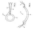
- Fig. 5 illustrates the ablation device of Fig. 4 in an open position.
- Fig. 6 shows the ablation device of Fig. 4 forming a closed loop.
- Fig. 7 illustrates the introducer of Fig. 2 being advanced around the pulmonary veins.
- Fig. 8 depicts the introducer extending around the pulmonary veins in order to size an ablation device.
- Fig. 9 shows the ablation device being connected to the introducer.
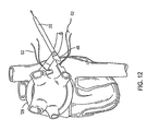
- Fig. 10 illustrates the ablation device coupled to the introducer and being advanced around the pulmonary veins via manipulation of the introducer.
- Fig. 11 illustrates the same thing as Fig. 10 at a later stage of the process.
- Fig. 13 is an expanded view of the connection between the introducer and the ablation device.
- Ablation system 10 includes a controller 12, which preferably operates to deliver focused ultrasound energy.
- Ablation system 10 may be used to wrap an ablation device 14 around the pulmonary veins at an epicardial location in order to create a pulmonary vein (PV) isolation ablation lesion.
- Ablation system 10 may further include a source 16 of a flowable material, which may be a bag of saline that provides a gravity feed to ablation device 14 via a standard luer connection 18.
- ablation device 14 includes a plurality of ablation elements 26 substantially aligned along a common axis and coupled together, preferably through integrally formed hinges in ablation device 14.
- substantially aligned along a common axis it is meant that there is little or no staggering between ablation elements 26 along the direction in which they are coupled together. It should be understood that ablation elements 26 may alternatively be coupled together with mechanical connections, rather than integrally formed hinges.
- a body 28 of ablation device 14 is preferably made of a polymeric material such as polycarbonate, polyetherimide (e.g., Ultem®), silicone, or urethane, and is preferably formed by injection molding.
- a polymeric material such as polycarbonate, polyetherimide (e.g., Ultem®), silicone, or urethane
- an outer surface of body 28 is smooth in order to limit the risk of catching ablation device 14 on patient tissue or otherwise causing trauma during insertion of ablation device 14.
- Ablation device 14 is configured to have a predetermined curvature that facilitates encircling an area of the heart while simultaneously permitting ablation device 14 to be straightened or flattened to minimize the overall width thereof.
- the latter (i.e., flattened) configuration facilitates insertion of ablation device 14 through a relatively smaller incision in the patient in order to reach the heart tissue, and thus is referred to herein as an "insertion configuration.”
- ablation device 14 is configured to permit at least two distinct configurations: a predetermined curvature (e.g., Fig. 5 ) to facilitate manipulation around the heart and a substantially straight, generally flattened shape (having little or no curvature) to facilitate insertion into the patient's body.
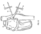
- Ablation device 14 may also be deformed into a third configuration, which is a generally closed loop as seen in Figs. 6 , 14 , and 15 . This third configuration will be described in further detail below.
- predetermined curvature is intended to convey that ablation device 14 is designed to assume a curved shape and maintain that general shape during certain intended manipulations. For example, while ablation device 14 may be maintained in a substantially straightened position for insertion, ablation device 14 is intended to resume and maintain a curved shape during manipulation about the heart. Additional forces may be applied on ablation device 14 in order to increase or decrease the degree of curvature, for example into the substantially closed loop third configuration illustrated in Fig. 6 .
- the use of "predetermined” is intended to convey that ablation device 14 maintains a generally curved shape while being positioned around a portion of the heart (that is, the "relaxed" state of ablation device 14, with no external forces applied thereto, is a generally curved configuration).
- ablation elements 26 are connected using a superelastic material, including, by way of example only, a memory metal such as Nitinol.
- a superelastic material is a material that can be subjected to very large strains without plastic deformation. The superelastic properties allow ablation device 14 to be substantially deformed to become substantially coplanar and then to return to the predetermined curvature.
- all ablation elements 26 may be interconnected using one or more strands of Nitinol, or another superelastic material, such that ablation device 14 may be substantially straightened for insertion into the patient through a relatively small incision, and thereafter manipulated into position about the heart in a generally curved configuration.
- the Nitinol or other superelastic material may take the form of a hinge wire that connects a plurality of ablation elements 26 to maintain the predetermined curvature.
- each ablation element 26 is contained in a housing, the edges of which may be angled to permit adjacent ablation elements 26 to have at least two relationships to one another: one in which they are substantially coplanar, resulting in a substantially flat configuration, and another in which they are at an angle, resulting in a generally curved configuration.
- the angle between the faces of adjacent ablation elements 26 when ablation device 14 is in its relaxed state may be adjusted based on the number of ablation elements 26, and may typically be between about 10 degrees and about 30 degrees.
- the hinges may be integrated wholly or partially into the housings.
- the adjustable configurations of ablation elements 26 may be implemented utilizing a spring system, such as a combination of mechanical hinges and/or springs.
- the mechanical hinges and/or springs may be used in conjunction with ablation elements 26 having angled edges 30 as described above.
- a standard guidewire structure (not shown), which generally includes a tightly coiled wire and, optionally, a core wire running therethrough, may be utilized to interconnect ablation elements 26.
- ablation device 14 may be deformed temporarily during insertion of ablation device 14 into the patient with the assistance of a sheath.
- the sheath applies a deforming force to ablation device 14 and assists in maintaining ablation elements 26 in a substantially straight insertion configuration.
- the sheath is a straight cylinder that is sized to accommodate ablation device 14 in the substantially straight insertion configuration.
- the sheath may be used to introduce ablation device 14 through an incision into the patient. Once ablation device 14 has been introduced through the incision, the sheath may be removed, and the tension caused by the superelastic wire or spring system will cause ablation device 14 to resume its predetermined curvature.
- a stylet may be used to deform ablation device 14 into the generally straight insertion configuration.
- Each ablation element 26 may include a guide tube shaped to receive the stylet therethrough.
- the guide tube may be internal to each ablation element 26 or mounted to the exterior of ablation device 14.
- the stylet applies a deforming force to ablation device 14 and assists in maintaining ablation elements 26 in a substantially straight configuration to facilitate insertion of ablation device 14 through an incision into the patient.
- the stylet may be withdrawn, at which time the restorative force caused by the superelastic wire or spring system will cause ablation device 14 to resume its predetermined curvature.
- Ablation elements 26 may be any element for directing and delivering ablating energy to the cardiac tissue, including, but not limited to, focused ultrasound elements, radio frequency (RF) elements, laser elements, and microwave elements.
- Ablation elements 26 preferably have a width of about 1 mm to about 15 mm, and more preferably of about 10 mm, and a length of about 2 mm to about 25 mm, and more preferably of about 12 mm.
- the RF element is coupled to an RF generator which transmits RF energy to the element.
- the RF element is preferably a stainless steel or gold plated copper electrode, although any suitable electrode may be used.
- ablation elements 26 are preferably spaced apart from the target tissue, by a distance of between about 0.5 mm to about 3 mm, and more preferably by about 1.5 mm.
- Ablation elements 26 are coupled to controller 12 via wires.
- the wires may be collectively incorporated into a plug 36 usable to couple ablation device 14 to controller 12 as shown in Fig. 1 .
- Controller 12 controls ablation, for example in the manner described herein.
- a source of ablation energy e.g., a signal generator
- One or more temperature sensors preferably thermocouples or thermistors, are positioned within recesses in the inner and outer lips of ablation device 14 in order to measure temperature. The temperature sensors are also coupled to controller 12, for example via plug 36, for monitoring purposes and to provide temperature feedback for controlling the ablation process as described herein.
- Each ablation element 26 may also have a membrane that contains the flowable material within a fluid chamber to provide a conformable interface with the tissue to be ablated.
- the membrane may include openings through which the flowable material may leak or weep, and each membrane may be fed by an individual inlet leading thereto.
- the flowable material is preferably supplied at an average flow rate of at least about 0.24 cc/sec, more preferably at least about 0.50 cc/sec, and most preferably at least about 1.0 cc/sec to each ablation element 26, although lower or higher flow rates may be used.
- the flowable material is preferably delivered to the inlet of ablation device 14 at a set pressure that results in the desired average flow rate through ablation elements 26.
- the flowable material may be heated or cooled as desired or required by passing it through a heat exchanger 44 prior to delivery to the inlet of ablation device 14 (e.g., luer connection 18 as seen in Fig. 1 ).
- the flowable material is preferably delivered at a temperature of no more than about 40 degrees C, and more preferably at a temperature of no more than about 25 degrees C, to cool the tissue and/or ablation elements 26.
- a fluid permeable, porous structure such as gauze, may be also positioned to hold the flowable material within the fluid chamber and prevent direct contact between ablation elements 26 and the tissue being ablated.
- the system further includes an introducer 20, illustrated in Figs. 2 and 3 , which is advanced around the pulmonary veins as shown in Figs. 7 and 8 and described below.
- introducer 20 preferably forms a substantially closed loop in an unbiased configuration, with a small offset near its distal tip 22 as shown in Fig. 3 .
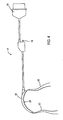
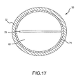
- Fig. 16 depicts introducer 20 and torque transfer device 60, which includes a rigid shaft 62 that is designed to be inserted into a lumen 61 ( Fig. 17 ) of introducer 20.
- torque transfer device 60 also includes a handle 64 on the proximal end. More preferably, handle 64 interlocks with a corresponding connection 46 on the proximal end of introducer 20.
- shaft 62 of torque transfer device 60 is made of a material that resists twisting forces, such as steel or stainless steel. Of course, any relatively rigid material may be used, including, without limitation, other metals and composite materials.
- Introducer 20 has an elongated flexible body having a proximal end 68, a distal end 70, and an intermediate portion 72 therebetween.
- Distal end 70 is configured to form at least a partial loop when in a resting, unbiased shape. That is, the relaxed configuration of distal end 70 is at least a partial loop.
- the elongated flexible body also includes lumen 61 extending from proximal end 68 to a point between proximal end 68 and the point at which distal end 70 begins to curve.
- Lumen 61 is designed to accommodate shaft 62 of torque transfer device 60.
- proximal end 68 of introducer 20 may include a connector, such as snap-fit connector 46, that is configured to receive handle 64 of torque transfer device 60. This helps to maximize torque transfer from handle 64 to proximal end 68 of introducer 20.
- Introducer 20 may be made using polymers, including, without limitation, etched polytetrafluoroethylene (PTFE), polyether block amides, nylon and other thermoplastic elastomers. Once such elastomer is Pebax® made by Arkema, Inc. Pebax of various durometers may also be used, including, without limitation, Pebax 30D to Pebax 70D.
- PTFE etched polytetrafluoroethylene
- Pebax® made by Arkema, Inc.
- Pebax of various durometers may also be used, including, without limitation, Pebax 30D to Pebax 70D.
- One of ordinary skill in the art will select the components to use in making introducer 20 based on the desired level of flexibility that is needed for a specific application of ablation system 10.
- the braided wire assembly may be formed in a standard braid pattern, for example, 16 wires at 45-60 picks per inch ("PPI").
- the braided wire assembly may have a varying braid density.
- the braided wire assembly may be characterized by a first braid density at proximal end 68 of introducer 20 and then transition to one or more different braid densities approaching distal end 70 of introducer 20.
- the braid density at distal end 70 may be greater or less than the braid density at proximal end 68.
- the number of picks per inch at the base (proximal end) is about 50 and the number of picks per inch at the depth at which the torque transfer device is inserted is about 10.
- the braided wire assembly is used in conjunction with torque transfer device 60, though it is also contemplated that the braided wire assembly may be used instead of torque transfer device 60.
- Introducer 20 may be used as a sizing device for sizing ablation device 14.
- introducer 20 may have size indicators 24 usable to determine the appropriate size of ablation device 14.
- the size of ablation device 14 is effectively determined by the number of ablation elements. It is also contemplated, however, that other methodologies for sizing ablation device 14 may be used.
- introducer 20 is inserted into the patient and passed through an incision in the pericardial reflection adjacent the right superior pulmonary vein adjacent the transverse pericardial sinus.
- introducer 20 is inserted in a generally straight configuration.
- a straightening introducer 74 ( Fig. 16 ) may be employed to good advantage in the insertion of introducer 20 into the patient.
- introducer 20 may be advanced through the transverse pericardial sinus, around the left superior and inferior pulmonary veins, and out through another incision in the pericardial reflection near the right inferior pulmonary vein.
- the appropriate size of ablation device 14 may then be read using indicators 24 imprinted on introducer 20. For example, in Fig. 8 , size indicators 24 of introducer 20 read "12," indicating that an ablation device 14 having 12 ablation elements will substantially encircle the pulmonary veins.
- ablation device 14 may be coupled to proximal end 68 of introducer 20 with any suitable connection, such as mating snap fit connectors 46 described above and shown in Figs. 9 , 13 , and 16 . It should be understood that the appropriate size of ablation device 14 may also be determined using a device or method independent of introducer 20. Ablation device 14 is preferably introduced into the patient while straightened, optionally through the use of a sheath, stylet, or other straightening device.
- Introducer 20 is then pulled further, as shown in Figs. 10 and 11 , in order to manipulate ablation device 14 and wrap ablation device 14 about the pulmonary veins.
- the sheath, stylet, or other straightening device may be removed in order to permit ablation device 14 to resume its predetermined curvature for manipulation about the pulmonary veins.
- introducer 20 may be detached from ablation device 14 by detaching a releasable assembly 48 from ablation device 14.
- releasable assembly 48 is detached by simply cutting one or more sutures 50 ( Fig. 13 ) that hold releasable assembly 48 to the device 14.
- snap fit connection 46 between introducer 20 and ablation device 14 may be releasable to permit decoupling introducer 20 at the same place introducer 20 is initially coupled to ablation device 24 without the need to cut one or more sutures 50.
- Ablation device 14 may then be locked to itself in a substantially closed-loop configuration to encircle all or part of the pulmonary veins.
- Device 14 has elongate elements, such as sutures 52, at both ends, which can be tensioned and cinched together to lock the ends of device 14 to each other using tourniquets 54 and suture snares 56 as shown in Figs. 6 , 14 , 15 , and 16 .
- ablation device 14 has two opposing pairs of sutures 52, though other numbers and configurations of sutures 52 are possible.
- Sutures 52 are tensioned using tourniquets 54 to approximate the ends of ablation device 14, such that tensioning sutures 52 forces the ends of ablation device 14 together.
- the sizing of ablation device 14 (which may be determined using introducer 20, as described above) provides a snug fit around all or part of the pulmonary veins such that tensioning sutures 52 forces ablation device 14 into contact with the epicardial surface.
- Hemostats 58 or other suitable devices may be used to pinch or crimp tourniquets 54 in order to secure ablation device 14 in place about the pulmonary veins as seen in Fig. 15 .
- ablation device 14 may utilize a locking mechanism, such as a buckle or other releasable locking mechanism, to be locked to itself and thereby secured in place about the pulmonary veins.
- Ablation device 14 may also contain a suction well to assist device 14 in adhering to the tissue to be ablated.
- the suction well may take any form, and is preferably formed between the inner and outer lips of body 28 of ablation device 14.
- the suction well may have a suction port coupled to a vacuum source through a lumen.
- the vacuum source may be activated to cause the suction well to hold ablation element 26 against the tissue to be ablated.
- the suction port preferably has a cross-sectional size that is no more than about 10% of the cross-sectional size of the lumen.
- Controller 12 preferably activates ablation elements 26 in a predetermined manner.
- predetermined manner is intended to refer to a non-random sequence.
- ablation is carried out at adjacent ablation elements 26.
- Ablation may also be carried out at a number of pairs of adjacent ablation elements 26, such as the first and second ablation elements 26 and the fifth and sixth ablation elements 26.
- another pair or pairs of adjacent ablation elements 26 are activated, such as the third and fourth and seventh and eighth ablation elements 26.
- the continuity of the ablation between adjacent ablation elements 26 may be confirmed in any suitable manner.
- controller 12 may energize every other ablation element 26, every third ablation element 26, or a limited number of ablation elements 26, such as no more than four. Controller 12 may also activate less than about 50%, and even less than about 30%, of the total ablation area at one time (for ablation device 14, a percentage of the total ablation area is effectively a percentage of the total number of ablation elements 26).
- ablation device 14 is designed to achieve and maintain particular near surface (NS) temperatures during an ablation procedure.
- ablation device 14 may be designed to maintain a near surface (NS) temperature of about 0 degree C to about 80 degrees C, more preferably about 20 degrees C to about 80 degrees C, and most preferably about 40 degrees C to about 80 degrees C.
- the temperature can be adjusted by changing the flow rate of the flowable material, the temperature of the flowable material, and/or the power delivered to ablation elements 26.
- ablation is controlled based on temperature measured by the temperature sensors.
- controller 12 may incorporate a multiplexer that delivers ablating energy only to those ablation elements 26 having a temperature below a threshold temperature.
- the multiplexer may deliver ablating energy only to the coldest ablation elements 26 or only to those ablation elements registering the coolest temperatures.
- the temperature response may be analyzed to determine the appropriate ablation technique.
- the analysis may be a comparison of the temperature response to temperature response curves of known tissue types.
- the temperature response curves may be developed empirically or may be calculated.
- the temperature response may also consider other variables input by the user, including, but not limited to, blood temperature, blood flow rate, and the presence and amount of fat.
- the amount of energy delivered to the tissue may also be taken into account in characterizing the tissue.
- controller 12 preferably determines the appropriate ablation technique to produce the desired far surface (FS) temperature.
- controller 12 determines the amount of time required to reach a desired FS temperature when the NS is maintained at a temperature of less than about 60 degrees C. Controller 12 preferably maintains an adequate flow rate and temperature of the flowable material to maintain the desired NS temperature. Controller 12 monitors the temperature of the NS with the temperature sensors. After the calculated amount of time has elapsed, controller 12 automatically stops delivering ablating energy to ablation elements 26. Alternatively, the ablation may take place until the NS reaches a target temperature as sensed by the temperature sensors. The continuity of the ablation may then be checked in any manner described herein.
- Ablation device 14 preferably delivers ultrasound energy focused in at least one dimension.
- ablation device 14 preferably delivers focused ultrasound having a focal length of about 2 mm to about 20 mm, more preferably of about 2 mm to about 12 mm, and most preferably of about 8 mm.
- a focus is spaced apart from a bottom (or contact) surface of ablation device 14 along a focal axis (FA) within the stated ranges.
- the focused ultrasound also forms an angle of about 10 degrees to about 170 degrees, more preferably of about 30 degrees to about 90 degrees, and most preferably of about 60 degrees relative to the FA.
- a piezoelectric transducer is utilized as an ultrasonic ablation element 26.
- the transducer is preferably mounted within a housing having an enclosure and a top that fits over the enclosure.
- the enclosure may have curved lips on both sides of the enclosure that generally conform to the curvature of the transducer.
- the transducer preferably has a length of about 0.43 inch, a width of about 0.35 inch, and a thickness of about 0.017 inch.
- the transducer has a radius of curvature (R) consistent with the preferred focal lengths described above.
- the transducer forms an angle (A) with the focus (F) within the preferred angle ranges described above.
- An advantage of using focused ultrasonic energy is that the energy can be concentrated within the tissue.
- Another advantage of using focused ultrasound is that the energy diverges after reaching the focus, thereby reducing the possibility of damaging tissue beyond the target tissue as compared to collimated ultrasonic energy.
- the collimated ultrasound energy not absorbed by the target tissue travels through the heart chamber and remains concentrated on a relatively small area when it reaches the endocardial surface on the other side of the chamber.
- the present invention reduces the likelihood of damage to other structures since the ultrasonic energy diverges beyond the focus and is spread over a larger area.
- the focused ultrasonic energy is preferably produced with a curved transducer
- the focused ultrasonic energy may be produced with any suitable structure.
- acoustic lensing may be used to provide focused ultrasound.
- the acoustic lens can be used with a flat piezoelectric element and matching layer.
- the ultrasound energy is preferably emitted directly toward the tissue, the ultrasound energy may also be reflected off a surface and directed toward the tissue.
- the energy may also be produced by a number of small transducers oriented to focus or concentrate ultrasonic energy, such as at least about 90% of the energy, within the preferred angle ranges and radius of curvature described herein when viewed along a longitudinal axis or along the FA.
- a multi-element acoustic phased array may be used to provide an acoustic beam-steering capability from one or more cells.
- One skilled in the art can also appreciate the use of multiple matching layers, focusing acoustic lenses, and non-focusing acoustic windows and the like.
- the focused energy may be produced in a number of different ways, including other ways not mentioned here.
- ablation device 14 is operated during two different time periods while varying at least one characteristic of ablation device 14, such as the frequency of the ablating energy, the power of the ablating energy, the position of the focus relative to the tissue, and/or the ablating time.
- ablation device 14 may be operated at varying frequencies over time to ablate tissue in a controlled manner.
- ablation device 14 is preferably operated to create a transmural lesion by controlling the delivery of energy to the tissue.
- ablation device 14 may, of course, be operated at a single frequency.
- the transducer is activated at a frequency of about 2 MHz to about 7 MHz, and preferably of about 3.5 MHz, and a power of about 80 watts to about 150 watts, and preferably of about 130 watts, in short bursts.
- the transducer may be activated for about 0.01 second to about 2.0 seconds, and preferably for about 1.2 seconds.
- the transducer is inactive for about 2 seconds to about 90 seconds, more preferably about 5 seconds to about 80 seconds, and most preferably about 45 seconds between activations. In this manner, a controlled amount of accumulated energy can be delivered to the tissue in short bursts to heat tissue at and near the focus while minimizing the impact of blood cooling at the FS.
Landscapes
- Health & Medical Sciences (AREA)
- Surgery (AREA)
- Life Sciences & Earth Sciences (AREA)
- Heart & Thoracic Surgery (AREA)
- Pathology (AREA)
- Oral & Maxillofacial Surgery (AREA)
- Engineering & Computer Science (AREA)
- Biomedical Technology (AREA)
- Nuclear Medicine, Radiotherapy & Molecular Imaging (AREA)
- Medical Informatics (AREA)
- Molecular Biology (AREA)
- Animal Behavior & Ethology (AREA)
- General Health & Medical Sciences (AREA)
- Public Health (AREA)
- Veterinary Medicine (AREA)
- Surgical Instruments (AREA)
Claims (12)
- Inserter, der dazu angepasst ist, eine Abtragungsvorrichtung in den zu behandelnden Bereich einzuführen und einen Bereich oder wenigstens einen Umfangsabschnitt um eine oder mehrere Lungenvenen entlang einer epikardialen Fläche abzumessen, wobei der Inserter aufweist:einen länglichen Körper mit einem distalen Ende (70), einem proximalen Ende (68) und einem dazwischen angeordneten mittleren Abschnitt (72), wobei das distale Ende (70) dazu ausgebildet ist, wenigstens eine Teilschlaufe zu bilden, wenn diese in einer ruhenden, nicht vorgespannten Form ist, und der längliche Körper einen Einsatz aufweist, der an dem distalen Ende (70) oder dem mittleren Abschnitt (72) angeordnet ist;einen am proximalen Ende des länglichen Körpers angeordneten Handgriff (64); undeinen Schaft (62), der fest mit dem Handgriff (64) verbunden ist und sich zum Unterstützen beim Übertragen von Drehmoment vom Handgriff (64) zum distalen Ende (70) und/oder zum mittleren Abschnitt (72) des länglichen Körpers zu dem Einsatz des länglichen Körpers erstreckt.
- Inserter nach Anspruch 1, bei dem
der längliche Körper ein Lumen (61) aufweist, das sich von dem proximalen Ende (68) zu einem Punkt innerhalb des mittleren Abschnitts (72) erstreckt;
der Einsatz wenigstens ein über das Lumen (61) zugänglicher Stecker (73) ist, wobei der Stecker (73) dazu ausgebildet ist, ein Drehmoment in den mittleren Abschnitt (72) des länglichen Körpers einzubringen; und
der Schaft (62) fest mit dem Handgriff (64) verbunden ist und sich zum Unterstützen beim Übertragen von Drehmoment vom Handgriff (64) zum mittleren Abschnitt (72) vom Handgriff (64) zu dem wenigstens einen Stecker (73) erstreckt. - Inserter nach Anspruch 2, bei dem der längliche, flexible Körper des Inserters (20) wenigstens zwei Stecker (73) umfasst und der Schaft (62) wenigstens zwei Enden aufweist, die dazu ausgebildet sind, in die wenigstens zwei Stecker (73) zu passen.
- Inserter nach einem der vorhergehenden Ansprüche, ferner mit einer Mehrzahl von Messindikatoren (24) entlang einer Länge des länglichen Körpers, wobei die Mehrzahl von Messindikatoren (24) eine Distanz anzeigen, die von der wenigstens einen Teilschlaufe, die in der Nähe des distalen Endes (70) des Inserters gebildet ist, gemessen wird.
- Inserter nach einem der vorhergehenden Ansprüche, bei dem das proximale Ende (68) des Inserters (20) ferner einen Verbinder aufweist, der dazu ausgebildet ist, den Handgriff (64) zu empfangen.
- Inserter nach Anspruch 5, bei dem das proximale Ende (68) des Inserters ferner einen Schnappverbinder (46) aufweist, der dazu ausgebildet ist, den Handgriff (64) zu empfangen.
- Inserter nach einem der vorhergehenden Ansprüche, bei dem ein Querschnitt des länglichen, flexiblen Körpers am proximalen Ende (68) größer als ein Querschnitt des länglichen, flexiblen Körpers am distalen Ende (70) ist.
- Inserter nach einem der vorhergehenden Ansprüche, bei dem der längliche Körper des Inserters (20) ferner eine geflochtene Drahtanordnung (71) aufweist, die sich vom proximalen Ende (68) in Richtung des distalen Endes (70) erstreckt.
- Inserter nach einem der vorhergehenden Ansprüche, bei dem der Schaft (62) aus einem Material besteht, das Verwindungskräften standhält.
- Inserter nach einem der vorhergehenden Ansprüche, bei dem der Schaft (62) aus Stahl besteht.
- Inserter nach einem der vorhergehenden Ansprüche, bei dem der Einsatz eine Kerbe aufweist und der Schaft (62) in einem flachen Kopf endet, der mit der Kerbe zusammenpasst.
- Bausatz zum Verwenden in einer lateralen Thorakotomieprozedur, mit:einem Inserter (20) nach einem der vorhergehenden Ansprüche, aufweisend:einen länglichen, flexiblen Körper, der ein proximales Ende (68), ein distales Ende (70) und einen dazwischen angeordneten mittleren Abschnitt (72) aufweist,bei dem das distale Ende (20) wenigstens eine Teilschlaufe in einem Ruhezustand bildet, wobei der längliche, flexible Körper ferner ein Lumen (61) aufweist, das sich dorthindurch vom proximalen Ende (68) zu einem Punkt zwischen dem proximalen Ende (68) und einem Punkt erstreckt, an dem das distale Ende (70) beginnt, sich zu krümmen,wobei der längliche, flexible Körper ferner wenigstens einen über das Lumen (61) zugänglichen Drehmomenteinbringstecker (73) umfasst, wobei der Stecker (73) dazu ausgebildet ist, ein Drehmoment in den mittleren Abschnitt (72) des länglichen Körpers einzubringen; undeine Drehmomentübertragungsvorrichtung (60) mit einem Handgriff (64) und einem Schaft (62), der fest an dem Handgriff (64) befestigt ist, wobei der Schaft (62) dazu ausgebildet ist, durch das Lumen (61) und in den wenigstens einen Stecker (73) eingerührt zu werden, wobei ein in den Handgriff (64) eingebrachtes Drehmoment über den Schaft (62) zum mittleren Abschnitt (72) des Inserters (20) übertragen wird.
Applications Claiming Priority (3)
| Application Number | Priority Date | Filing Date | Title |
|---|---|---|---|
| US81585306P | 2006-06-23 | 2006-06-23 | |
| US11/646,528 US20070299438A1 (en) | 2006-06-23 | 2006-12-28 | Torque transfer agent for introducer and method |
| PCT/US2007/071760 WO2007149968A2 (en) | 2006-06-23 | 2007-06-21 | Torque transfer agent for introducer and method |
Publications (4)
| Publication Number | Publication Date |
|---|---|
| EP2032060A2 EP2032060A2 (de) | 2009-03-11 |
| EP2032060A4 EP2032060A4 (de) | 2011-04-20 |
| EP2032060B1 true EP2032060B1 (de) | 2013-04-17 |
| EP2032060B9 EP2032060B9 (de) | 2013-06-26 |
Family
ID=38834382
Family Applications (1)
| Application Number | Title | Priority Date | Filing Date |
|---|---|---|---|
| EP07798873.1A Not-in-force EP2032060B9 (de) | 2006-06-23 | 2007-06-21 | Drehmomentübertragungsmittel für eine einführvorrichtung |
Country Status (5)
| Country | Link |
|---|---|
| US (1) | US20070299438A1 (de) |
| EP (1) | EP2032060B9 (de) |
| JP (1) | JP5090445B2 (de) |
| CN (1) | CN101472533B (de) |
| WO (1) | WO2007149968A2 (de) |
Families Citing this family (7)
| Publication number | Priority date | Publication date | Assignee | Title |
|---|---|---|---|---|
| US8102734B2 (en) * | 2007-02-08 | 2012-01-24 | St. Jude Medical, Atrial Fibrillation Division, Inc. | High intensity focused ultrasound transducer with acoustic lens |
| KR101497458B1 (ko) | 2011-08-25 | 2015-03-02 | 코비디엔 엘피 | 관강 조직의 치료용 시스템, 장치 및 방법 |
| AU2014284381B2 (en) | 2013-07-01 | 2019-04-18 | Zurich Medical Corporation | Apparatus and method for intravascular measurements |
| US10835183B2 (en) | 2013-07-01 | 2020-11-17 | Zurich Medical Corporation | Apparatus and method for intravascular measurements |
| US10736690B2 (en) | 2014-04-24 | 2020-08-11 | Medtronic Ardian Luxembourg S.A.R.L. | Neuromodulation catheters and associated systems and methods |
| CN111789588A (zh) * | 2020-07-29 | 2020-10-20 | 绍兴梅奥心磁医疗科技有限公司 | 标测导管 |
| WO2023107332A1 (en) * | 2021-12-06 | 2023-06-15 | Edwards Lifesciences Corporation | Sizer for left atrial appendage |
Family Cites Families (20)
| Publication number | Priority date | Publication date | Assignee | Title |
|---|---|---|---|---|
| US4763670A (en) * | 1986-09-19 | 1988-08-16 | Microvasive, Inc. | Microbiological specimen sampling device |
| US5908446A (en) * | 1994-07-07 | 1999-06-01 | Cardiac Pathways Corporation | Catheter assembly, catheter and multi-port introducer for use therewith |
| US5607462A (en) * | 1993-09-24 | 1997-03-04 | Cardiac Pathways Corporation | Catheter assembly, catheter and multi-catheter introducer for use therewith |
| US5497774A (en) * | 1993-11-03 | 1996-03-12 | Daig Corporation | Guiding introducer for left atrium |
| US5628316A (en) * | 1993-11-03 | 1997-05-13 | Swartz; John F. | Guiding introducer system for use in the right atrium |
| US5564440A (en) * | 1993-11-03 | 1996-10-15 | Daig Corporation | Method for mopping and/or ablation of anomalous conduction pathways |
| US5656028A (en) * | 1993-11-03 | 1997-08-12 | Daig Corporation | Process for the nonsurgical mapping and/or treatment of ectopic atrial tachycardia using a guiding introducer |
| US5427119A (en) * | 1993-11-03 | 1995-06-27 | Daig Corporation | Guiding introducer for right atrium |
| US5575766A (en) * | 1993-11-03 | 1996-11-19 | Daig Corporation | Process for the nonsurgical mapping and treatment of atrial arrhythmia using catheters guided by shaped guiding introducers |
| US5846223A (en) * | 1993-11-03 | 1998-12-08 | Daig Corporation | Diagnosis and treatment of atrial flutter in the right atrium |
| US5814027A (en) * | 1993-11-03 | 1998-09-29 | Daig Corporation | Guiding introducer used for medical procedures within the right ventricle associated with the right ventricular outflow track |
| US5690611A (en) * | 1994-07-08 | 1997-11-25 | Daig Corporation | Process for the treatment of atrial arrhythima using a catheter guided by shaped giding introducers |
| US5814029A (en) * | 1994-11-03 | 1998-09-29 | Daig Corporation | Guiding introducer system for use in ablation and mapping procedures in the left ventricle |
| US5823955A (en) * | 1995-11-20 | 1998-10-20 | Medtronic Cardiorhythm | Atrioventricular valve tissue ablation catheter and method |
| US7052493B2 (en) * | 1996-10-22 | 2006-05-30 | Epicor Medical, Inc. | Methods and devices for ablation |
| US6120500A (en) * | 1997-11-12 | 2000-09-19 | Daig Corporation | Rail catheter ablation and mapping system |
| EP1267986B1 (de) * | 2000-03-31 | 2006-05-10 | Medtronic, Inc. | Lenkmechanismus |
| US6733500B2 (en) * | 2000-03-31 | 2004-05-11 | Medtronic, Inc. | Method and system for delivering a medical electrical lead within a venous system |
| US7493156B2 (en) * | 2002-01-07 | 2009-02-17 | Cardiac Pacemakers, Inc. | Steerable guide catheter with pre-shaped rotatable shaft |
| US7369901B1 (en) * | 2004-02-11 | 2008-05-06 | Pacesetter, Inc. | Myocardial lead and lead system |
-
2006
- 2006-12-28 US US11/646,528 patent/US20070299438A1/en not_active Abandoned
-
2007
- 2007-06-21 CN CN2007800233245A patent/CN101472533B/zh not_active Expired - Fee Related
- 2007-06-21 EP EP07798873.1A patent/EP2032060B9/de not_active Not-in-force
- 2007-06-21 WO PCT/US2007/071760 patent/WO2007149968A2/en not_active Ceased
- 2007-06-21 JP JP2009516718A patent/JP5090445B2/ja not_active Expired - Fee Related
Also Published As
| Publication number | Publication date |
|---|---|
| US20070299438A1 (en) | 2007-12-27 |
| WO2007149968A2 (en) | 2007-12-27 |
| CN101472533A (zh) | 2009-07-01 |
| JP2009540959A (ja) | 2009-11-26 |
| EP2032060A4 (de) | 2011-04-20 |
| EP2032060A2 (de) | 2009-03-11 |
| CN101472533B (zh) | 2012-03-21 |
| EP2032060B9 (de) | 2013-06-26 |
| JP5090445B2 (ja) | 2012-12-05 |
| WO2007149968A3 (en) | 2008-11-27 |
Similar Documents
| Publication | Publication Date | Title |
|---|---|---|
| AU2007260895B2 (en) | Apparatus and method for ablating tissue | |
| CA2499223C (en) | Methods and devices for ablation | |
| US6645202B1 (en) | Apparatus and method for ablating tissue | |
| CA2450075C (en) | Methods and devices for ablation | |
| WO2008083318A2 (en) | Ablation device and method with connector | |
| JP2009540960A5 (de) | ||
| US20050245918A1 (en) | Methods and devices for ablation | |
| US20070293855A1 (en) | Methods and devices for ablation | |
| AU2002315167A1 (en) | Methods and devices for ablation | |
| EP2032060B9 (de) | Drehmomentübertragungsmittel für eine einführvorrichtung | |
| US7678109B2 (en) | Ablation device and method comprising movable ablation elements | |
| AU2007254588B2 (en) | Apparatus and method for ablating tissue |
Legal Events
| Date | Code | Title | Description |
|---|---|---|---|
| PUAI | Public reference made under article 153(3) epc to a published international application that has entered the european phase |
Free format text: ORIGINAL CODE: 0009012 |
|
| 17P | Request for examination filed |
Effective date: 20081119 |
|
| AK | Designated contracting states |
Kind code of ref document: A2 Designated state(s): AT BE BG CH CY CZ DE DK EE ES FI FR GB GR HU IE IS IT LI LT LU LV MC MT NL PL PT RO SE SI SK TR |
|
| AX | Request for extension of the european patent |
Extension state: AL BA HR MK RS |
|
| RAP1 | Party data changed (applicant data changed or rights of an application transferred) |
Owner name: ST. JUDE MEDICAL, ATRIAL FIBRILLATION DIVISION, IN |
|
| DAX | Request for extension of the european patent (deleted) | ||
| A4 | Supplementary search report drawn up and despatched |
Effective date: 20110322 |
|
| RIC1 | Information provided on ipc code assigned before grant |
Ipc: A61B 18/18 20060101AFI20080303BHEP Ipc: A61B 18/14 20060101ALI20110316BHEP |
|
| GRAP | Despatch of communication of intention to grant a patent |
Free format text: ORIGINAL CODE: EPIDOSNIGR1 |
|
| GRAS | Grant fee paid |
Free format text: ORIGINAL CODE: EPIDOSNIGR3 |
|
| GRAA | (expected) grant |
Free format text: ORIGINAL CODE: 0009210 |
|
| AK | Designated contracting states |
Kind code of ref document: B1 Designated state(s): AT BE BG CH CY CZ DE DK EE ES FI FR GB GR HU IE IS IT LI LT LU LV MC MT NL PL PT RO SE SI SK TR |
|
| REG | Reference to a national code |
Ref country code: GB Ref legal event code: FG4D |
|
| REG | Reference to a national code |
Ref country code: CH Ref legal event code: EP |
|
| REG | Reference to a national code |
Ref country code: IE Ref legal event code: FG4D |
|
| REG | Reference to a national code |
Ref country code: AT Ref legal event code: REF Ref document number: 606762 Country of ref document: AT Kind code of ref document: T Effective date: 20130515 |
|
| REG | Reference to a national code |
Ref country code: DE Ref legal event code: R096 Ref document number: 602007029852 Country of ref document: DE Effective date: 20130613 |
|
| REG | Reference to a national code |
Ref country code: AT Ref legal event code: MK05 Ref document number: 606762 Country of ref document: AT Kind code of ref document: T Effective date: 20130417 |
|
| REG | Reference to a national code |
Ref country code: LT Ref legal event code: MG4D |
|
| REG | Reference to a national code |
Ref country code: NL Ref legal event code: VDEP Effective date: 20130417 |
|
| PG25 | Lapsed in a contracting state [announced via postgrant information from national office to epo] |
Ref country code: BE Free format text: LAPSE BECAUSE OF FAILURE TO SUBMIT A TRANSLATION OF THE DESCRIPTION OR TO PAY THE FEE WITHIN THE PRESCRIBED TIME-LIMIT Effective date: 20130417 Ref country code: AT Free format text: LAPSE BECAUSE OF FAILURE TO SUBMIT A TRANSLATION OF THE DESCRIPTION OR TO PAY THE FEE WITHIN THE PRESCRIBED TIME-LIMIT Effective date: 20130417 Ref country code: IS Free format text: LAPSE BECAUSE OF FAILURE TO SUBMIT A TRANSLATION OF THE DESCRIPTION OR TO PAY THE FEE WITHIN THE PRESCRIBED TIME-LIMIT Effective date: 20130817 Ref country code: SE Free format text: LAPSE BECAUSE OF FAILURE TO SUBMIT A TRANSLATION OF THE DESCRIPTION OR TO PAY THE FEE WITHIN THE PRESCRIBED TIME-LIMIT Effective date: 20130417 Ref country code: LT Free format text: LAPSE BECAUSE OF FAILURE TO SUBMIT A TRANSLATION OF THE DESCRIPTION OR TO PAY THE FEE WITHIN THE PRESCRIBED TIME-LIMIT Effective date: 20130417 Ref country code: GR Free format text: LAPSE BECAUSE OF FAILURE TO SUBMIT A TRANSLATION OF THE DESCRIPTION OR TO PAY THE FEE WITHIN THE PRESCRIBED TIME-LIMIT Effective date: 20130718 Ref country code: ES Free format text: LAPSE BECAUSE OF FAILURE TO SUBMIT A TRANSLATION OF THE DESCRIPTION OR TO PAY THE FEE WITHIN THE PRESCRIBED TIME-LIMIT Effective date: 20130728 Ref country code: SI Free format text: LAPSE BECAUSE OF FAILURE TO SUBMIT A TRANSLATION OF THE DESCRIPTION OR TO PAY THE FEE WITHIN THE PRESCRIBED TIME-LIMIT Effective date: 20130417 Ref country code: FI Free format text: LAPSE BECAUSE OF FAILURE TO SUBMIT A TRANSLATION OF THE DESCRIPTION OR TO PAY THE FEE WITHIN THE PRESCRIBED TIME-LIMIT Effective date: 20130417 Ref country code: PT Free format text: LAPSE BECAUSE OF FAILURE TO SUBMIT A TRANSLATION OF THE DESCRIPTION OR TO PAY THE FEE WITHIN THE PRESCRIBED TIME-LIMIT Effective date: 20130819 |
|
| PG25 | Lapsed in a contracting state [announced via postgrant information from national office to epo] |
Ref country code: LV Free format text: LAPSE BECAUSE OF FAILURE TO SUBMIT A TRANSLATION OF THE DESCRIPTION OR TO PAY THE FEE WITHIN THE PRESCRIBED TIME-LIMIT Effective date: 20130417 Ref country code: CY Free format text: LAPSE BECAUSE OF FAILURE TO SUBMIT A TRANSLATION OF THE DESCRIPTION OR TO PAY THE FEE WITHIN THE PRESCRIBED TIME-LIMIT Effective date: 20130417 Ref country code: PL Free format text: LAPSE BECAUSE OF FAILURE TO SUBMIT A TRANSLATION OF THE DESCRIPTION OR TO PAY THE FEE WITHIN THE PRESCRIBED TIME-LIMIT Effective date: 20130417 Ref country code: BG Free format text: LAPSE BECAUSE OF FAILURE TO SUBMIT A TRANSLATION OF THE DESCRIPTION OR TO PAY THE FEE WITHIN THE PRESCRIBED TIME-LIMIT Effective date: 20130717 |
|
| PG25 | Lapsed in a contracting state [announced via postgrant information from national office to epo] |
Ref country code: EE Free format text: LAPSE BECAUSE OF FAILURE TO SUBMIT A TRANSLATION OF THE DESCRIPTION OR TO PAY THE FEE WITHIN THE PRESCRIBED TIME-LIMIT Effective date: 20130417 Ref country code: DK Free format text: LAPSE BECAUSE OF FAILURE TO SUBMIT A TRANSLATION OF THE DESCRIPTION OR TO PAY THE FEE WITHIN THE PRESCRIBED TIME-LIMIT Effective date: 20130417 Ref country code: CZ Free format text: LAPSE BECAUSE OF FAILURE TO SUBMIT A TRANSLATION OF THE DESCRIPTION OR TO PAY THE FEE WITHIN THE PRESCRIBED TIME-LIMIT Effective date: 20130417 Ref country code: SK Free format text: LAPSE BECAUSE OF FAILURE TO SUBMIT A TRANSLATION OF THE DESCRIPTION OR TO PAY THE FEE WITHIN THE PRESCRIBED TIME-LIMIT Effective date: 20130417 Ref country code: MC Free format text: LAPSE BECAUSE OF FAILURE TO SUBMIT A TRANSLATION OF THE DESCRIPTION OR TO PAY THE FEE WITHIN THE PRESCRIBED TIME-LIMIT Effective date: 20130417 |
|
| REG | Reference to a national code |
Ref country code: CH Ref legal event code: PL |
|
| PLBE | No opposition filed within time limit |
Free format text: ORIGINAL CODE: 0009261 |
|
| STAA | Information on the status of an ep patent application or granted ep patent |
Free format text: STATUS: NO OPPOSITION FILED WITHIN TIME LIMIT |
|
| PG25 | Lapsed in a contracting state [announced via postgrant information from national office to epo] |
Ref country code: NL Free format text: LAPSE BECAUSE OF FAILURE TO SUBMIT A TRANSLATION OF THE DESCRIPTION OR TO PAY THE FEE WITHIN THE PRESCRIBED TIME-LIMIT Effective date: 20130417 Ref country code: RO Free format text: LAPSE BECAUSE OF FAILURE TO SUBMIT A TRANSLATION OF THE DESCRIPTION OR TO PAY THE FEE WITHIN THE PRESCRIBED TIME-LIMIT Effective date: 20130417 |
|
| 26N | No opposition filed |
Effective date: 20140120 |
|
| REG | Reference to a national code |
Ref country code: IE Ref legal event code: MM4A |
|
| PG25 | Lapsed in a contracting state [announced via postgrant information from national office to epo] |
Ref country code: LI Free format text: LAPSE BECAUSE OF NON-PAYMENT OF DUE FEES Effective date: 20130630 Ref country code: CH Free format text: LAPSE BECAUSE OF NON-PAYMENT OF DUE FEES Effective date: 20130630 Ref country code: IE Free format text: LAPSE BECAUSE OF NON-PAYMENT OF DUE FEES Effective date: 20130621 |
|
| REG | Reference to a national code |
Ref country code: DE Ref legal event code: R097 Ref document number: 602007029852 Country of ref document: DE Effective date: 20140120 |
|
| PG25 | Lapsed in a contracting state [announced via postgrant information from national office to epo] |
Ref country code: MT Free format text: LAPSE BECAUSE OF FAILURE TO SUBMIT A TRANSLATION OF THE DESCRIPTION OR TO PAY THE FEE WITHIN THE PRESCRIBED TIME-LIMIT Effective date: 20130417 |
|
| REG | Reference to a national code |
Ref country code: FR Ref legal event code: PLFP Year of fee payment: 9 |
|
| PG25 | Lapsed in a contracting state [announced via postgrant information from national office to epo] |
Ref country code: TR Free format text: LAPSE BECAUSE OF FAILURE TO SUBMIT A TRANSLATION OF THE DESCRIPTION OR TO PAY THE FEE WITHIN THE PRESCRIBED TIME-LIMIT Effective date: 20130417 |
|
| PG25 | Lapsed in a contracting state [announced via postgrant information from national office to epo] |
Ref country code: HU Free format text: LAPSE BECAUSE OF FAILURE TO SUBMIT A TRANSLATION OF THE DESCRIPTION OR TO PAY THE FEE WITHIN THE PRESCRIBED TIME-LIMIT; INVALID AB INITIO Effective date: 20070621 Ref country code: LU Free format text: LAPSE BECAUSE OF NON-PAYMENT OF DUE FEES Effective date: 20130621 |
|
| PGFP | Annual fee paid to national office [announced via postgrant information from national office to epo] |
Ref country code: GB Payment date: 20150629 Year of fee payment: 9 |
|
| PGFP | Annual fee paid to national office [announced via postgrant information from national office to epo] |
Ref country code: FR Payment date: 20150617 Year of fee payment: 9 |
|
| PGFP | Annual fee paid to national office [announced via postgrant information from national office to epo] |
Ref country code: IT Payment date: 20150625 Year of fee payment: 9 |
|
| GBPC | Gb: european patent ceased through non-payment of renewal fee |
Effective date: 20160621 |
|
| REG | Reference to a national code |
Ref country code: FR Ref legal event code: ST Effective date: 20170228 |
|
| PG25 | Lapsed in a contracting state [announced via postgrant information from national office to epo] |
Ref country code: FR Free format text: LAPSE BECAUSE OF NON-PAYMENT OF DUE FEES Effective date: 20160630 |
|
| PG25 | Lapsed in a contracting state [announced via postgrant information from national office to epo] |
Ref country code: GB Free format text: LAPSE BECAUSE OF NON-PAYMENT OF DUE FEES Effective date: 20160621 |
|
| PG25 | Lapsed in a contracting state [announced via postgrant information from national office to epo] |
Ref country code: IT Free format text: LAPSE BECAUSE OF NON-PAYMENT OF DUE FEES Effective date: 20160621 |
|
| PGFP | Annual fee paid to national office [announced via postgrant information from national office to epo] |
Ref country code: DE Payment date: 20180627 Year of fee payment: 12 |
|
| REG | Reference to a national code |
Ref country code: DE Ref legal event code: R119 Ref document number: 602007029852 Country of ref document: DE |
|
| PG25 | Lapsed in a contracting state [announced via postgrant information from national office to epo] |
Ref country code: DE Free format text: LAPSE BECAUSE OF NON-PAYMENT OF DUE FEES Effective date: 20200101 |