EP2031501A2 - Apparatus for the culture and growth of cells to a three dimensional tissue - Google Patents
Apparatus for the culture and growth of cells to a three dimensional tissue Download PDFInfo
- Publication number
- EP2031501A2 EP2031501A2 EP20080011144 EP08011144A EP2031501A2 EP 2031501 A2 EP2031501 A2 EP 2031501A2 EP 20080011144 EP20080011144 EP 20080011144 EP 08011144 A EP08011144 A EP 08011144A EP 2031501 A2 EP2031501 A2 EP 2031501A2
- Authority
- EP
- European Patent Office
- Prior art keywords
- grid
- bypasses
- cells
- shells
- growing
- Prior art date
- Legal status (The legal status is an assumption and is not a legal conclusion. Google has not performed a legal analysis and makes no representation as to the accuracy of the status listed.)
- Granted
Links
Images


Classifications
-
- C—CHEMISTRY; METALLURGY
- C12—BIOCHEMISTRY; BEER; SPIRITS; WINE; VINEGAR; MICROBIOLOGY; ENZYMOLOGY; MUTATION OR GENETIC ENGINEERING
- C12M—APPARATUS FOR ENZYMOLOGY OR MICROBIOLOGY; APPARATUS FOR CULTURING MICROORGANISMS FOR PRODUCING BIOMASS, FOR GROWING CELLS OR FOR OBTAINING FERMENTATION OR METABOLIC PRODUCTS, i.e. BIOREACTORS OR FERMENTERS
- C12M25/00—Means for supporting, enclosing or fixing the microorganisms, e.g. immunocoatings
- C12M25/02—Membranes; Filters
-
- C—CHEMISTRY; METALLURGY
- C12—BIOCHEMISTRY; BEER; SPIRITS; WINE; VINEGAR; MICROBIOLOGY; ENZYMOLOGY; MUTATION OR GENETIC ENGINEERING
- C12M—APPARATUS FOR ENZYMOLOGY OR MICROBIOLOGY; APPARATUS FOR CULTURING MICROORGANISMS FOR PRODUCING BIOMASS, FOR GROWING CELLS OR FOR OBTAINING FERMENTATION OR METABOLIC PRODUCTS, i.e. BIOREACTORS OR FERMENTERS
- C12M21/00—Bioreactors or fermenters specially adapted for specific uses
- C12M21/08—Bioreactors or fermenters specially adapted for specific uses for producing artificial tissue or for ex-vivo cultivation of tissue
-
- C—CHEMISTRY; METALLURGY
- C12—BIOCHEMISTRY; BEER; SPIRITS; WINE; VINEGAR; MICROBIOLOGY; ENZYMOLOGY; MUTATION OR GENETIC ENGINEERING
- C12M—APPARATUS FOR ENZYMOLOGY OR MICROBIOLOGY; APPARATUS FOR CULTURING MICROORGANISMS FOR PRODUCING BIOMASS, FOR GROWING CELLS OR FOR OBTAINING FERMENTATION OR METABOLIC PRODUCTS, i.e. BIOREACTORS OR FERMENTERS
- C12M23/00—Constructional details, e.g. recesses, hinges
- C12M23/02—Form or structure of the vessel
-
- C—CHEMISTRY; METALLURGY
- C12—BIOCHEMISTRY; BEER; SPIRITS; WINE; VINEGAR; MICROBIOLOGY; ENZYMOLOGY; MUTATION OR GENETIC ENGINEERING
- C12M—APPARATUS FOR ENZYMOLOGY OR MICROBIOLOGY; APPARATUS FOR CULTURING MICROORGANISMS FOR PRODUCING BIOMASS, FOR GROWING CELLS OR FOR OBTAINING FERMENTATION OR METABOLIC PRODUCTS, i.e. BIOREACTORS OR FERMENTERS
- C12M41/00—Means for regulation, monitoring, measurement or control, e.g. flow regulation
Definitions
- the invention relates to an apparatus for the culture and growth of cells to a three dimensional tissue.
- reactors or fermentors are commonly used in the trade because they describe a controll mass transfer and a controll rate of reaction in the mass transfer.
- the apparatus for the culture and growth of cells to a three dimensional tissue of the invention consists of a laminar flow reactor, in which the growing of the cells takes place, a pump, a storage tank for a nutrient fluid and pipes connecting these parts to create a permanent circulation of the nutrient fluid through these parts.
- This is to obtain in an apparatus with a reactor whoose housing consists of three parts, two shells each with a hole used for an entrance or an outlet of the nutrient fluid, and between theese shells a chamber carrying a grid to support the biomaterial.
- the grid in the grid carrying chamber be surronded by a plurality of bypasses.
- theese bypasses it is possible to get a constant laminar flow in the whole area of the grid and it is further on possible to reach the maximum of the laminar flow without turbulences in this flow.
- the plurality of bypasses can be controlled by a handle or a motor to close the by-passes partly or completly to steer the run through of the nutrient fluid through the cell-mass.
- a slidable ring with the same scale of canals of the by-passes can be installed over the bypasses to cover and close the bypasses partly or completly.
- bypasses can have the form of an iris-diaphragm and an irisclamp to control the flow through theese bypasses.
- the shells of the reactor have each a flange to fasten one shell to the other shell and include between them the grid or the grid carring chamber.
- the shells include a big volume of fluid to create an equal flow of the fluid through the chamber between the two shells.
- one or more windows can be installed in the walls of the reactor showing the kind of flow and the growing of the cells.
- Another design of this apparatus has a grid carring a frame on the surface on the grid surrounding the center part of the grid for the growing of the cells und a another part surroundig the center part of the grid acting as a bypass.
- the apparatus can be equipped with a device for a simple take out the grid with the grown cell mass and to bring in a new grid for the growing cell mass located between the upper and the under shell consisting of a holder to carry a slidable carrier of the grid for growing the cell masses and the surrounding bypasses and consisting of an devive for moving the upper and the under shell away from the holder (to open the apparatus for taking out the grid with the grown cell mass) and to press the to shells against the holder (to close the apparatus for its working phase).
- a device for a simple take out the grid with the grown cell mass and to bring in a new grid for the growing cell mass located between the upper and the under shell consisting of a holder to carry a slidable carrier of the grid for growing the cell masses and the surrounding bypasses and consisting of an devive for moving the upper and the under shell away from the holder (to open the apparatus for taking out the grid with the grown cell mass) and to press the to shells against the holder (to close the apparatus for
- the carrier has on its upper side and on its under side sealings surrounding the grid and the bypasses to seal the carrier with the shells of the apparatus.
- the upper shell is slidable against the under shell in a direction of the flow of the nutrient fluid for a small distance to give the possibility to take out the carrier and to fill in a new carrier.
- the magnitude of the diameter of the canals is controlled by the motor for adjusting. It can have hydraulic means which press the shells and the sealings together in the growing phase of the cell mass to tighten the apparatus and which lift the upper shell from the under shell at the end of the growing process to give a possibility to take out the carrier out of the inner room between the two shells (it is the reactor room for the growing process) in an easy way.
- the laminar flow reactor 1 is connected with pump 2 by the pipe 3
- pipe 4 connects pump 3 with the storage tank 5 for the nutrient fluid and this tank is connected with the reactor 1 by pipe 6.
- the nutrient fluid flows in a circle from the tank 5 to the reactor1, from the reactor 1 to the pump 2 and from the pump 2 bach to the tank 5.
- a control box 7 controlls the velocity of the fluid in the pipes and holds the laminar flow in the reactor.
- Fig.2 is shown a crosssection of the reactor.
- Two shells 8,9 with a big interior 10 include and carry a chamber 11 with the grid 12 carrying the biomaterial.
- Each shell 8,9 has on its end a hole 13,14 connected with the pipes 3 and 4.
- In the frame 15 of the chamber 11 are in a circle many canals 17 used as bypasses.
- Theese are interrupted by a ring 18 with the same canals 17.
- By rotating the ring 18 with the handle 19 the bypasses are covered and closed partly or completly or are opend again.
- Fig.3 shows a view of the iris valve of a laminar flow reactor.
- the iris holder provided with a handle to rotate the iris in positions to let through more or less fluid.
- Fig.4 shows a reaktor with a grid 12 which is divided by a ring 22 in an inner part 23 where the cells are growing and an outer part 24 acting as bypass 17. Under the outer part 24 of the grid is situated a second grid (not shown) which can be rotated to covering the bypasses 17 partly or completly or to open the bypasses 17.
- a device 26 for a simple take out the grid 12 with the grown cell mass and to bring in a new grid 12 for the growing cell mass is shown in Fig.4 .
- This device 26 consists of a holder 27 with rails 28 on its both sides to carry a slidable carrier 29 of the grid 12 for growing the cell masses and the surrounding bypasses 17.
- the carrier 29 has on its upper side and on its under side sealings 30 surrounding the grid 12 and the bypasses 17 to seal the carrier 29 with the shells 8.9 of the apparatus.
- the upper shell 9 is slidable against the under shell 8 in a direction of the flow of the nutrient fluid for a small distance to give the possibility to take out the carrier 29 and to fill in a new carrier 29.
- the magnitude of the diameter of the canals is controlled by the motor for adjusting 31. It can be hydraulic means which press the shells and the sealings together in the growing phase of the cell mass to tighten the apparatus and which lift the upper shell from the under shell at the end of the growing process to give a possibility to take out the carrier 29 out of the inner room between the two shells (it is the reactor room for the growing process) in an easy way.
- In the carrier 29 is a shaft 32 connecting the motor 31 with the ring of by-passes 17 to controll the passage of the bypasses 17.
- a handle 33 helps to slide the carrier 29.
- Fig.7 shows a plate used as a shelter 34 with six holes 35.
- This shelter is to place on the grid 12 in the carrier if there is to observe the growth of cells in dependence with the time.
- each hole is brought a little part of a cell mass.
- the carrier is brought in in the apparatus. After each day (or hour or another time) of the growing one hole is closed by a cover put over one hole, then the next hole and so on to interrupt the flow of the nutrient through this hole. In this way it is possible to observe the growth on the grid in the holes.
Landscapes
- Health & Medical Sciences (AREA)
- Life Sciences & Earth Sciences (AREA)
- Engineering & Computer Science (AREA)
- Chemical & Material Sciences (AREA)
- Wood Science & Technology (AREA)
- Organic Chemistry (AREA)
- Bioinformatics & Cheminformatics (AREA)
- Zoology (AREA)
- Biomedical Technology (AREA)
- Genetics & Genomics (AREA)
- Sustainable Development (AREA)
- Microbiology (AREA)
- Biotechnology (AREA)
- Biochemistry (AREA)
- General Engineering & Computer Science (AREA)
- General Health & Medical Sciences (AREA)
- Immunology (AREA)
- Molecular Biology (AREA)
- Clinical Laboratory Science (AREA)
- Analytical Chemistry (AREA)
- Apparatus Associated With Microorganisms And Enzymes (AREA)
Abstract
Description
- The invention relates to an apparatus for the culture and growth of cells to a three dimensional tissue.
- Known in the art is a rotational reactor using continuous spin to mimic a microgravity environment. The spin reduces the hydro-dynamic shear ten-fold. The reduction of shear is important to maintain the cell structure and integrity. Another property in the design is the increased mass transfer to support large aggregates. A limitation with this design is that it cannot be used to adequately controll in the groth of large amounts of cells in a scaffold.
- Stirred methods, or suspension bioreactors, are commonly used in life sciences and chemical research. The major limitation of theese types of bioreactors is that the design cannot be transferred to industrial sizes. By scaling up such bioreactors, the resulting increase in the shear forces limits the sizes of cultures and hence limits the practical applications. Industriell scale bioreactors include for example, the Air Lift Bioreactor. The Air Lift reactor is a low input, high yield alternative to stirred tank bioreactors. Its low shear allows for good oxygen transfer, but the tissue culture sizes and volumes cannot be adequately controlled.
- The terms reactors or fermentors are commonly used in the trade because they describe a controll mass transfer and a controll rate of reaction in the mass transfer.
- is to build an apparatus for the culture and growth of cells in a homogenous thickness over a wide plain (surface) to a three dimensional tissue to be used e.g. in hospitals
- The apparatus for the culture and growth of cells to a three dimensional tissue of the invention consists of a laminar flow reactor, in which the growing of the cells takes place, a pump, a storage tank for a nutrient fluid and pipes connecting these parts to create a permanent circulation of the nutrient fluid through these parts.
- For the growing of the cells it is important, that the flow through the mass of growing cells is steady and laminar.
- This is to obtain in an apparatus with a reactor whoose housing consists of three parts, two shells each with a hole used for an entrance or an outlet of the nutrient fluid, and between theese shells a chamber carrying a grid to support the biomaterial.
- In this apparatus should the grid in the grid carrying chamber be surronded by a plurality of bypasses. With theese bypasses it is possible to get a constant laminar flow in the whole area of the grid and it is further on possible to reach the maximum of the laminar flow without turbulences in this flow.
- For this purpose it is important in this apparatus that the plurality of bypasses can be controlled by a handle or a motor to close the by-passes partly or completly to steer the run through of the nutrient fluid through the cell-mass.
- For this purpose it is also advantageous to have a grid in the form of a circle surounded by the channels of the bypasses.
- In this case a slidable ring with the same scale of canals of the by-passes can be installed over the bypasses to cover and close the bypasses partly or completly.
- In this apparatus the bypasses can have the form of an iris-diaphragm and an irisclamp to control the flow through theese bypasses.
- The shells of the reactor have each a flange to fasten one shell to the other shell and include between them the grid or the grid carring chamber.
- The shells include a big volume of fluid to create an equal flow of the fluid through the chamber between the two shells.
- In the housing of the reactor of this Installation one or more windows can be installed in the walls of the reactor showing the kind of flow and the growing of the cells.
- Another design of this apparatus has a grid carring a frame on the surface on the grid surrounding the center part of the grid for the growing of the cells und a another part surroundig the center part of the grid acting as a bypass.
- The apparatus can be equipped with a device for a simple take out the grid with the grown cell mass and to bring in a new grid for the growing cell mass located between the upper and the under shell consisting of a holder to carry a slidable carrier of the grid for growing the cell masses and the surrounding bypasses and consisting of an devive for moving the upper and the under shell away from the holder (to open the apparatus for taking out the grid with the grown cell mass) and to press the to shells against the holder (to close the apparatus for its working phase).
- The carrier has on its upper side and on its under side sealings surrounding the grid and the bypasses to seal the carrier with the shells of the apparatus. The upper shell is slidable against the under shell in a direction of the flow of the nutrient fluid for a small distance to give the possibility to take out the carrier and to fill in a new carrier. The magnitude of the diameter of the canals is controlled by the motor for adjusting. It can have hydraulic means which press the shells and the sealings together in the growing phase of the cell mass to tighten the apparatus and which lift the upper shell from the under shell at the end of the growing process to give a possibility to take out the carrier out of the inner room between the two shells (it is the reactor room for the growing process) in an easy way.
-
- Fig.1
- shows a block diagramm of the installation for the culture and growth, of cells to a three dimensional tissue.
- Fig 2
- shows a crosssection through the laminar flow reactor with a grid for growing cells surounded by bypasses.
- Fig.3
- shows a view of the iris valve of a laminar flow reactor.
- Fig.4
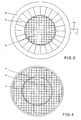
- shows a grid with a growing area in the midth and a surrounding bypass area.
- Fig.5
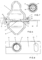
- shows a device for take out and bring in the grid carrier.
- Fig.6
- shows the grid carrier of
Fig.5 . - Fig.7
- a shelter over the grid with six holes to observe the growth
- In the block diagramm of
Fig. 1 thelaminar flow reactor 1 is connected withpump 2 by thepipe 3,pipe 4 connectspump 3 with thestorage tank 5 for the nutrient fluid and this tank is connected with thereactor 1 bypipe 6. The nutrient fluid flows in a circle from thetank 5 to the reactor1, from thereactor 1 to thepump 2 and from thepump 2 bach to thetank 5. - A
control box 7 controlls the velocity of the fluid in the pipes and holds the laminar flow in the reactor. - In
Fig.2 is shown a crosssection of the reactor. Twoshells big interior 10 include and carry achamber 11 with thegrid 12 carrying the biomaterial. Eachshell hole pipes frame 15 of thechamber 11 are in a circlemany canals 17 used as bypasses. Theese are interrupted by aring 18 with thesame canals 17. By rotating thering 18 with thehandle 19 the bypasses are covered and closed partly or completly or are opend again. - In this way can be obtained a continous laminar flow of the nutrient fluid through the reactor: The big inner of the
shells shells bypasses 17 surroundig thegrid 12 avoid turbulences of the fluid passing thegrid 12. -
Fig.3 shows a view of the iris valve of a laminar flow reactor. In this picture is the iris holder provided with a handle to rotate the iris in positions to let through more or less fluid. -
Fig.4 shows a reaktor with agrid 12 which is divided by aring 22 in aninner part 23 where the cells are growing and anouter part 24 acting asbypass 17. Under theouter part 24 of the grid is situated a second grid (not shown) which can be rotated to covering thebypasses 17 partly or completly or to open thebypasses 17. - In this apparatus there is the possibillity to install an automatic controll for holding the laminar flow by measuring the pressure in the
shell 9 behind thegrid 12 by a measuringinstrument 25 connected with thecontrol box 7 connected with a not shown motor moving thehandle 19 or another item to open and close the bypasses. - Also it is possible to install a device 26 for a simple take out the
grid 12 with the grown cell mass and to bring in anew grid 12 for the growing cell mass. The apparatus with this device 26 is shown inFig.4 . Between the upper 9 and theunder shell 8 is located this device 26. It consists of aholder 27 withrails 28 on its both sides to carry aslidable carrier 29 of thegrid 12 for growing the cell masses and the surrounding bypasses 17. Thecarrier 29 has on its upper side and on its under side sealings 30 surrounding thegrid 12 and thebypasses 17 to seal thecarrier 29 with the shells 8.9 of the apparatus. Theupper shell 9 is slidable against the undershell 8 in a direction of the flow of the nutrient fluid for a small distance to give the possibility to take out thecarrier 29 and to fill in anew carrier 29. The magnitude of the diameter of the canals is controlled by the motor for adjusting 31. It can be hydraulic means which press the shells and the sealings together in the growing phase of the cell mass to tighten the apparatus and which lift the upper shell from the under shell at the end of the growing process to give a possibility to take out thecarrier 29 out of the inner room between the two shells (it is the reactor room for the growing process) in an easy way. In thecarrier 29 is ashaft 32 connecting themotor 31 with the ring of by-passes 17 to controll the passage of thebypasses 17. Ahandle 33 helps to slide thecarrier 29. - In
Fig.7 shows a plate used as ashelter 34 with sixholes 35. This shelter is to place on thegrid 12 in the carrier if there is to observe the growth of cells in dependence with the time. In each hole is brought a little part of a cell mass. The carrier is brought in in the apparatus. After each day (or hour or another time) of the growing one hole is closed by a cover put over one hole, then the next hole and so on to interrupt the flow of the nutrient through this hole. In this way it is possible to observe the growth on the grid in the holes. -
- 1
- reactor
- 2
- pump
- 3
- pipe
- 4
- pipe
- 5
- storage tank
- 6
- pipe
- 7
- control box
- 8
- shell
- 9
- shell
- 10
- interior of the shell
- 11
- chamber
- 12
- grid
- 13
- hole (inlet)
- 14
- hole (outlet)
- 15
- flange
- 16
- frame
- 17
- canal for a bypass
- 18
- ring
- 19
- handle
- 20
- iris holder
- 21
- iris
- 22
- ring
- 23
- inner part of the grid
- 24
- outer part of the grid
- 25
- measure instrument
- 26
- device
- 27
- holder
- 28
- rail
- 29
- carrier
- 30
- sealing
- 31
- motor for adjusting
- 32
- shaft
- 33
- handle
- 34
- plate used as a shelter
- 35
- hole
Claims (15)
- Method for the growth of cells to a three dimensional tissue, in which biomaterial is taken on a grid , the grid is put in the midth of a laminar flow of a nutrient and the grid is brought in the midth of a circle of bypasses.
- Method according claim 1,
in which the bypasses are closed or opened to controll the flow to have a permanent laminar flow through the grid with its cells at the highest level without turbulences. - Apparatus for the culture and growth of cells to a three dimensional tissue, consisting of a laminar flow reactor, in which the growing of the cells takes place, a pump, a storage tank for a nutrient fluid and pipes connecting these parts to create a circulation of the nutrient fluid through these parts.
- Apparatus according claim 1
with a reactor whoose housing consists of three parts, two shells each with a hole used for an entrance or an outlet of the nutrient fluid and between theese shells a chamber carrying a grid to support the biomaterial. - Apparatus according claim 1 and 2,
with a grid carrying support what is surronded by a plurality of by-passes. - Apparatus according claim 5
with a support in form of a ring which has canals used as bypasses. - Apparatus according claim 3 to 6,
with a plurality of bypasses controlled by a handle or a motor to close the bypasses partly or completly to steer the run through of the nutrient fluid through the cell-mass. - Apparatus according claim 5
with a grid in the form of a circle surounded by the channels of the bypasses. - Apparatus according claim 7
with a slidable ring with the same scale of holes of the by-passes can be installed over the outlets or inlets of the bypasses to cover and close the bypasses partly or completly. - Apparatus according claim 1 to 4,
with a control unit in form of a slidable ring over the plurality of bypasses to steering the flow through the bypasses by covering the bypasses partly or completly. - Apparatus according claim 3 to 6,
with bypasses in Form of an iris-diaphragm and an irisclamp to control the flow through theese bypasses. - Apparatus according claim 3 to 6,
with shells having each a flange to fasten one shell to the other shell and including the grid bearing ring. - Apparatus according claim 3 to 6,
with shells including a big volume of fluid to create an equal flow of the fluid through the chamber between the two shells. - Apparatus according to claim 3 and 4
with a grid carriing a frame surrounding the center part of the grid for the growing of the cells und a surroundig part of the grid acting as a bypass. - Apparatus according claim 3 and 4,
with a device for a simple take out the grid with the grown cell mass and to bring in a new grid for the growing cell mass located between the upper and the under shell consisting of the first hand of a holder to carry a slidable carrier with the grid for growing the cell masses and the surrounding bypasses and consisting on the second hand of an devive for moving the upper and the under shell away from the holder (to open the apparatus for taking out the grid with the grown cell mass) and to press the to shells against the holder (to close the apparatus for its working phase).
Applications Claiming Priority (1)
| Application Number | Priority Date | Filing Date | Title |
|---|---|---|---|
| US11/895,645 US20090061508A1 (en) | 2007-08-27 | 2007-08-27 | Laminar flow reactor |
Publications (3)
| Publication Number | Publication Date |
|---|---|
| EP2031501A2 true EP2031501A2 (en) | 2009-03-04 |
| EP2031501A3 EP2031501A3 (en) | 2009-05-06 |
| EP2031501B1 EP2031501B1 (en) | 2015-08-05 |
Family
ID=40293662
Family Applications (1)
| Application Number | Title | Priority Date | Filing Date |
|---|---|---|---|
| EP08011144.6A Active EP2031501B1 (en) | 2007-08-27 | 2008-06-19 | Apparatus for the culture and growth of cells to a three dimensional tissue |
Country Status (2)
| Country | Link |
|---|---|
| US (1) | US20090061508A1 (en) |
| EP (1) | EP2031501B1 (en) |
Cited By (2)
| Publication number | Priority date | Publication date | Assignee | Title |
|---|---|---|---|---|
| WO2012045756A1 (en) | 2010-10-04 | 2012-04-12 | Medizinische Hochschule Hannover | Process for producing three-dimensional tissue |
| WO2012156682A1 (en) * | 2011-05-16 | 2012-11-22 | Parker Hannifin Manufacturing Limited | Bioreactor chamber |
Citations (1)
| Publication number | Priority date | Publication date | Assignee | Title |
|---|---|---|---|---|
| WO2006088029A1 (en) | 2005-02-15 | 2006-08-24 | School Juridical Person Kitasato Gakuen | Method of producing high-density cultured tissue and high-density cultured tissue |
Family Cites Families (8)
| Publication number | Priority date | Publication date | Assignee | Title |
|---|---|---|---|---|
| US4095974A (en) * | 1975-09-24 | 1978-06-20 | Thagard Technology Company | High temperature chemical reaction processes utilizing fluid-wall reactors |
| US6159739A (en) * | 1997-03-26 | 2000-12-12 | University Of Washington | Device and method for 3-dimensional alignment of particles in microfabricated flow channels |
| US6217937B1 (en) * | 1998-07-15 | 2001-04-17 | Cornell Research Foundation, Inc. | High throughput OMVPE apparatus |
| US7351376B1 (en) * | 2000-06-05 | 2008-04-01 | California Institute Of Technology | Integrated active flux microfluidic devices and methods |
| EP1485465A2 (en) * | 2002-02-28 | 2004-12-15 | Arizona Board of Regents, acting for and on behalf of Arizona State University | Microcapillary bioreactor for growth of biological tissue |
| US7115230B2 (en) * | 2003-06-26 | 2006-10-03 | Intel Corporation | Hydrodynamic focusing devices |
| EP1697494B1 (en) * | 2003-12-09 | 2012-02-22 | Ben-Gurion University Of The Negev Research And Development Authority | Pulse-medium perfusion bioreactor with improved mass transport for multiple 3-d cell constructs |
| WO2006122088A1 (en) * | 2005-05-09 | 2006-11-16 | Isolagen Technologies, Inc. | Cell culture apparatus |
-
2007
- 2007-08-27 US US11/895,645 patent/US20090061508A1/en not_active Abandoned
-
2008
- 2008-06-19 EP EP08011144.6A patent/EP2031501B1/en active Active
Patent Citations (1)
| Publication number | Priority date | Publication date | Assignee | Title |
|---|---|---|---|---|
| WO2006088029A1 (en) | 2005-02-15 | 2006-08-24 | School Juridical Person Kitasato Gakuen | Method of producing high-density cultured tissue and high-density cultured tissue |
Cited By (4)
| Publication number | Priority date | Publication date | Assignee | Title |
|---|---|---|---|---|
| WO2012045756A1 (en) | 2010-10-04 | 2012-04-12 | Medizinische Hochschule Hannover | Process for producing three-dimensional tissue |
| US9222074B2 (en) | 2010-10-04 | 2015-12-29 | Medizinische Hochschule Hannover | Process for producing three-dimensional tissue |
| WO2012156682A1 (en) * | 2011-05-16 | 2012-11-22 | Parker Hannifin Manufacturing Limited | Bioreactor chamber |
| US9422516B2 (en) | 2011-05-16 | 2016-08-23 | Parker-Hannifin Manufacturing Limited | Bioreactor chamber |
Also Published As
| Publication number | Publication date |
|---|---|
| EP2031501B1 (en) | 2015-08-05 |
| US20090061508A1 (en) | 2009-03-05 |
| EP2031501A3 (en) | 2009-05-06 |
Similar Documents
| Publication | Publication Date | Title |
|---|---|---|
| US9683208B2 (en) | Horizontal single use pressurizable modular multi-agitator microbial fermentator | |
| JP5657886B2 (en) | Reactor | |
| EP0368621B1 (en) | Method of separating living cells | |
| CN203196987U (en) | Anaerobic-aerobiotic compatible biological slurry reactor | |
| CN105255731A (en) | Circulation filling type cell culture system and bioreactor of circulation filling type cell culture system | |
| CN208266081U (en) | A kind of biogas residue aerobic compost reactor | |
| JPH08228762A (en) | Bioreactor and method of using the same | |
| EP2031501B1 (en) | Apparatus for the culture and growth of cells to a three dimensional tissue | |
| US5227066A (en) | Apparatus for separating living cells | |
| CN210584555U (en) | Auxiliary device for preparing compound in proportion for chemical explanation of middle school student | |
| CN210394377U (en) | Anaerobe culture system | |
| CN104195043B (en) | A kind of can the horizontal rotation type bio-reactor of sterilizing online | |
| RU2355751C1 (en) | Vortex reactor for carrying out biotechnological processes under microgravity conditions | |
| CN110819526A (en) | An in vitro simulation device for intestinal biomimetic fermentation and digestion | |
| CN208261508U (en) | A kind of innoxious landfill system of danger wastes | |
| CN204058482U (en) | A kind of can the horizontal rotation type bio-reactor of sterilizing online | |
| CN210030737U (en) | Lymphocyte culture apparatus for biological analysis | |
| CN107475112A (en) | A kind of full-automatic digestion facility separated for microcarrier with zooblast | |
| CN206970488U (en) | A kind of edible fungus fermented device | |
| CN207775218U (en) | A kind of full automatic microorganism installation for fermenting | |
| CN206599569U (en) | A kind of reactor for dry anaerobic fermentation | |
| CN105695313B (en) | A kind of positive conveyance tubular type bioreactor | |
| CN214539587U (en) | A simulation device for tailings pond silting phenomenon | |
| RU242452U1 (en) | Laboratory setup for studying hydrometallurgical processes involving microorganisms | |
| CN220531444U (en) | Experimental airtight circulation stirring mechanism with jacket temperature and ventilation functions |
Legal Events
| Date | Code | Title | Description |
|---|---|---|---|
| PUAI | Public reference made under article 153(3) epc to a published international application that has entered the european phase |
Free format text: ORIGINAL CODE: 0009012 |
|
| AK | Designated contracting states |
Kind code of ref document: A2 Designated state(s): AT BE BG CH CY CZ DE DK EE ES FI FR GB GR HR HU IE IS IT LI LT LU LV MC MT NL NO PL PT RO SE SI SK TR |
|
| AX | Request for extension of the european patent |
Extension state: AL BA MK RS |
|
| PUAL | Search report despatched |
Free format text: ORIGINAL CODE: 0009013 |
|
| AK | Designated contracting states |
Kind code of ref document: A3 Designated state(s): AT BE BG CH CY CZ DE DK EE ES FI FR GB GR HR HU IE IS IT LI LT LU LV MC MT NL NO PL PT RO SE SI SK TR |
|
| AX | Request for extension of the european patent |
Extension state: AL BA MK RS |
|
| RIC1 | Information provided on ipc code assigned before grant |
Ipc: C12M 3/00 20060101AFI20090327BHEP |
|
| RIN1 | Information on inventor provided before grant (corrected) |
Inventor name: RIZVI, SEYED W. H. Inventor name: GILLE, CHRISTOPH Inventor name: VON SCHROEDER, HERBERT P. Inventor name: HOLMES, CHRIS Inventor name: ISRAELOWITZ, MEIR |
|
| RIN1 | Information on inventor provided before grant (corrected) |
Inventor name: VON SCHROEDER, HERBERT P. Inventor name: RIZVI, SEYED W. H. Inventor name: GILLE, CHRISTOPH Inventor name: ISRAELOWITZ, MEIR Inventor name: HOLM, CHRIS |
|
| 17P | Request for examination filed |
Effective date: 20090915 |
|
| AKX | Designation fees paid |
Designated state(s): AT BE BG CH CY CZ DE DK EE ES FI FR GB GR HR HU IE IS IT LI LT LU LV MC MT NL NO PL PT RO SE SI SK TR |
|
| 17Q | First examination report despatched |
Effective date: 20140113 |
|
| GRAP | Despatch of communication of intention to grant a patent |
Free format text: ORIGINAL CODE: EPIDOSNIGR1 |
|
| INTG | Intention to grant announced |
Effective date: 20150327 |
|
| GRAS | Grant fee paid |
Free format text: ORIGINAL CODE: EPIDOSNIGR3 |
|
| GRAA | (expected) grant |
Free format text: ORIGINAL CODE: 0009210 |
|
| AK | Designated contracting states |
Kind code of ref document: B1 Designated state(s): AT BE BG CH CY CZ DE DK EE ES FI FR GB GR HR HU IE IS IT LI LT LU LV MC MT NL NO PL PT RO SE SI SK TR |
|
| REG | Reference to a national code |
Ref country code: GB Ref legal event code: FG4D |
|
| REG | Reference to a national code |
Ref country code: CH Ref legal event code: EP |
|
| REG | Reference to a national code |
Ref country code: AT Ref legal event code: REF Ref document number: 740734 Country of ref document: AT Kind code of ref document: T Effective date: 20150815 |
|
| REG | Reference to a national code |
Ref country code: IE Ref legal event code: FG4D |
|
| REG | Reference to a national code |
Ref country code: DE Ref legal event code: R096 Ref document number: 602008039352 Country of ref document: DE |
|
| REG | Reference to a national code |
Ref country code: AT Ref legal event code: MK05 Ref document number: 740734 Country of ref document: AT Kind code of ref document: T Effective date: 20150805 |
|
| REG | Reference to a national code |
Ref country code: LT Ref legal event code: MG4D |
|
| REG | Reference to a national code |
Ref country code: NL Ref legal event code: MP Effective date: 20150805 |
|
| PG25 | Lapsed in a contracting state [announced via postgrant information from national office to epo] |
Ref country code: GR Free format text: LAPSE BECAUSE OF FAILURE TO SUBMIT A TRANSLATION OF THE DESCRIPTION OR TO PAY THE FEE WITHIN THE PRESCRIBED TIME-LIMIT Effective date: 20151106 Ref country code: FI Free format text: LAPSE BECAUSE OF FAILURE TO SUBMIT A TRANSLATION OF THE DESCRIPTION OR TO PAY THE FEE WITHIN THE PRESCRIBED TIME-LIMIT Effective date: 20150805 Ref country code: LV Free format text: LAPSE BECAUSE OF FAILURE TO SUBMIT A TRANSLATION OF THE DESCRIPTION OR TO PAY THE FEE WITHIN THE PRESCRIBED TIME-LIMIT Effective date: 20150805 Ref country code: LT Free format text: LAPSE BECAUSE OF FAILURE TO SUBMIT A TRANSLATION OF THE DESCRIPTION OR TO PAY THE FEE WITHIN THE PRESCRIBED TIME-LIMIT Effective date: 20150805 Ref country code: NO Free format text: LAPSE BECAUSE OF FAILURE TO SUBMIT A TRANSLATION OF THE DESCRIPTION OR TO PAY THE FEE WITHIN THE PRESCRIBED TIME-LIMIT Effective date: 20151105 |
|
| PG25 | Lapsed in a contracting state [announced via postgrant information from national office to epo] |
Ref country code: HR Free format text: LAPSE BECAUSE OF FAILURE TO SUBMIT A TRANSLATION OF THE DESCRIPTION OR TO PAY THE FEE WITHIN THE PRESCRIBED TIME-LIMIT Effective date: 20150805 Ref country code: AT Free format text: LAPSE BECAUSE OF FAILURE TO SUBMIT A TRANSLATION OF THE DESCRIPTION OR TO PAY THE FEE WITHIN THE PRESCRIBED TIME-LIMIT Effective date: 20150805 Ref country code: IS Free format text: LAPSE BECAUSE OF FAILURE TO SUBMIT A TRANSLATION OF THE DESCRIPTION OR TO PAY THE FEE WITHIN THE PRESCRIBED TIME-LIMIT Effective date: 20151205 Ref country code: PT Free format text: LAPSE BECAUSE OF FAILURE TO SUBMIT A TRANSLATION OF THE DESCRIPTION OR TO PAY THE FEE WITHIN THE PRESCRIBED TIME-LIMIT Effective date: 20151207 Ref country code: SE Free format text: LAPSE BECAUSE OF FAILURE TO SUBMIT A TRANSLATION OF THE DESCRIPTION OR TO PAY THE FEE WITHIN THE PRESCRIBED TIME-LIMIT Effective date: 20150805 Ref country code: ES Free format text: LAPSE BECAUSE OF FAILURE TO SUBMIT A TRANSLATION OF THE DESCRIPTION OR TO PAY THE FEE WITHIN THE PRESCRIBED TIME-LIMIT Effective date: 20150805 Ref country code: PL Free format text: LAPSE BECAUSE OF FAILURE TO SUBMIT A TRANSLATION OF THE DESCRIPTION OR TO PAY THE FEE WITHIN THE PRESCRIBED TIME-LIMIT Effective date: 20150805 |
|
| PG25 | Lapsed in a contracting state [announced via postgrant information from national office to epo] |
Ref country code: NL Free format text: LAPSE BECAUSE OF FAILURE TO SUBMIT A TRANSLATION OF THE DESCRIPTION OR TO PAY THE FEE WITHIN THE PRESCRIBED TIME-LIMIT Effective date: 20150805 |
|
| PG25 | Lapsed in a contracting state [announced via postgrant information from national office to epo] |
Ref country code: DK Free format text: LAPSE BECAUSE OF FAILURE TO SUBMIT A TRANSLATION OF THE DESCRIPTION OR TO PAY THE FEE WITHIN THE PRESCRIBED TIME-LIMIT Effective date: 20150805 Ref country code: EE Free format text: LAPSE BECAUSE OF FAILURE TO SUBMIT A TRANSLATION OF THE DESCRIPTION OR TO PAY THE FEE WITHIN THE PRESCRIBED TIME-LIMIT Effective date: 20150805 Ref country code: IT Free format text: LAPSE BECAUSE OF FAILURE TO SUBMIT A TRANSLATION OF THE DESCRIPTION OR TO PAY THE FEE WITHIN THE PRESCRIBED TIME-LIMIT Effective date: 20150805 Ref country code: SK Free format text: LAPSE BECAUSE OF FAILURE TO SUBMIT A TRANSLATION OF THE DESCRIPTION OR TO PAY THE FEE WITHIN THE PRESCRIBED TIME-LIMIT Effective date: 20150805 Ref country code: CZ Free format text: LAPSE BECAUSE OF FAILURE TO SUBMIT A TRANSLATION OF THE DESCRIPTION OR TO PAY THE FEE WITHIN THE PRESCRIBED TIME-LIMIT Effective date: 20150805 |
|
| REG | Reference to a national code |
Ref country code: DE Ref legal event code: R097 Ref document number: 602008039352 Country of ref document: DE |
|
| PG25 | Lapsed in a contracting state [announced via postgrant information from national office to epo] |
Ref country code: RO Free format text: LAPSE BECAUSE OF FAILURE TO SUBMIT A TRANSLATION OF THE DESCRIPTION OR TO PAY THE FEE WITHIN THE PRESCRIBED TIME-LIMIT Effective date: 20150805 |
|
| PLBE | No opposition filed within time limit |
Free format text: ORIGINAL CODE: 0009261 |
|
| STAA | Information on the status of an ep patent application or granted ep patent |
Free format text: STATUS: NO OPPOSITION FILED WITHIN TIME LIMIT |
|
| REG | Reference to a national code |
Ref country code: FR Ref legal event code: PLFP Year of fee payment: 9 |
|
| 26N | No opposition filed |
Effective date: 20160509 |
|
| PG25 | Lapsed in a contracting state [announced via postgrant information from national office to epo] |
Ref country code: SI Free format text: LAPSE BECAUSE OF FAILURE TO SUBMIT A TRANSLATION OF THE DESCRIPTION OR TO PAY THE FEE WITHIN THE PRESCRIBED TIME-LIMIT Effective date: 20150805 |
|
| PG25 | Lapsed in a contracting state [announced via postgrant information from national office to epo] |
Ref country code: BE Free format text: LAPSE BECAUSE OF FAILURE TO SUBMIT A TRANSLATION OF THE DESCRIPTION OR TO PAY THE FEE WITHIN THE PRESCRIBED TIME-LIMIT Effective date: 20150805 |
|
| PG25 | Lapsed in a contracting state [announced via postgrant information from national office to epo] |
Ref country code: MC Free format text: LAPSE BECAUSE OF FAILURE TO SUBMIT A TRANSLATION OF THE DESCRIPTION OR TO PAY THE FEE WITHIN THE PRESCRIBED TIME-LIMIT Effective date: 20150805 |
|
| REG | Reference to a national code |
Ref country code: CH Ref legal event code: PL |
|
| GBPC | Gb: european patent ceased through non-payment of renewal fee |
Effective date: 20160619 |
|
| REG | Reference to a national code |
Ref country code: IE Ref legal event code: MM4A |
|
| PG25 | Lapsed in a contracting state [announced via postgrant information from national office to epo] |
Ref country code: LI Free format text: LAPSE BECAUSE OF NON-PAYMENT OF DUE FEES Effective date: 20160630 Ref country code: CH Free format text: LAPSE BECAUSE OF NON-PAYMENT OF DUE FEES Effective date: 20160630 |
|
| PG25 | Lapsed in a contracting state [announced via postgrant information from national office to epo] |
Ref country code: IE Free format text: LAPSE BECAUSE OF NON-PAYMENT OF DUE FEES Effective date: 20160619 Ref country code: GB Free format text: LAPSE BECAUSE OF NON-PAYMENT OF DUE FEES Effective date: 20160619 |
|
| REG | Reference to a national code |
Ref country code: FR Ref legal event code: PLFP Year of fee payment: 10 |
|
| PG25 | Lapsed in a contracting state [announced via postgrant information from national office to epo] |
Ref country code: HU Free format text: LAPSE BECAUSE OF FAILURE TO SUBMIT A TRANSLATION OF THE DESCRIPTION OR TO PAY THE FEE WITHIN THE PRESCRIBED TIME-LIMIT; INVALID AB INITIO Effective date: 20080619 Ref country code: CY Free format text: LAPSE BECAUSE OF FAILURE TO SUBMIT A TRANSLATION OF THE DESCRIPTION OR TO PAY THE FEE WITHIN THE PRESCRIBED TIME-LIMIT Effective date: 20150805 |
|
| REG | Reference to a national code |
Ref country code: FR Ref legal event code: PLFP Year of fee payment: 11 |
|
| PG25 | Lapsed in a contracting state [announced via postgrant information from national office to epo] |
Ref country code: LU Free format text: LAPSE BECAUSE OF NON-PAYMENT OF DUE FEES Effective date: 20160619 Ref country code: TR Free format text: LAPSE BECAUSE OF FAILURE TO SUBMIT A TRANSLATION OF THE DESCRIPTION OR TO PAY THE FEE WITHIN THE PRESCRIBED TIME-LIMIT Effective date: 20150805 Ref country code: MT Free format text: LAPSE BECAUSE OF NON-PAYMENT OF DUE FEES Effective date: 20160630 |
|
| PG25 | Lapsed in a contracting state [announced via postgrant information from national office to epo] |
Ref country code: BG Free format text: LAPSE BECAUSE OF FAILURE TO SUBMIT A TRANSLATION OF THE DESCRIPTION OR TO PAY THE FEE WITHIN THE PRESCRIBED TIME-LIMIT Effective date: 20150805 |
|
| P01 | Opt-out of the competence of the unified patent court (upc) registered |
Effective date: 20230601 |
|
| PGFP | Annual fee paid to national office [announced via postgrant information from national office to epo] |
Ref country code: DE Payment date: 20250605 Year of fee payment: 18 |
|
| PGFP | Annual fee paid to national office [announced via postgrant information from national office to epo] |
Ref country code: FR Payment date: 20250626 Year of fee payment: 18 |