EP2031424A1 - Antireflective structure and antireflective moulded body - Google Patents
Antireflective structure and antireflective moulded body Download PDFInfo
- Publication number
- EP2031424A1 EP2031424A1 EP08015126A EP08015126A EP2031424A1 EP 2031424 A1 EP2031424 A1 EP 2031424A1 EP 08015126 A EP08015126 A EP 08015126A EP 08015126 A EP08015126 A EP 08015126A EP 2031424 A1 EP2031424 A1 EP 2031424A1
- Authority
- EP
- European Patent Office
- Prior art keywords
- face
- fine protrusions
- diameter
- antireflective
- base face
- Prior art date
- Legal status (The legal status is an assumption and is not a legal conclusion. Google has not performed a legal analysis and makes no representation as to the accuracy of the status listed.)
- Granted
Links
- 230000003667 anti-reflective effect Effects 0.000 title claims abstract description 96
- 239000002245 particle Substances 0.000 claims description 25
- 239000000758 substrate Substances 0.000 claims description 24
- 229920005989 resin Polymers 0.000 claims description 13
- 239000011347 resin Substances 0.000 claims description 13
- 239000000463 material Substances 0.000 claims description 11
- 238000006243 chemical reaction Methods 0.000 claims description 5
- MQUIHBQDYYAEMH-UHFFFAOYSA-N methedrone Chemical compound CNC(C)C(=O)C1=CC=C(OC)C=C1 MQUIHBQDYYAEMH-UHFFFAOYSA-N 0.000 description 13
- 229920003229 poly(methyl methacrylate) Polymers 0.000 description 12
- 239000004926 polymethyl methacrylate Substances 0.000 description 12
- 238000002310 reflectometry Methods 0.000 description 12
- 239000011295 pitch Substances 0.000 description 11
- 238000012360 testing method Methods 0.000 description 11
- 239000004417 polycarbonate Substances 0.000 description 10
- 238000011156 evaluation Methods 0.000 description 7
- 239000010408 film Substances 0.000 description 7
- 239000012780 transparent material Substances 0.000 description 7
- YXFVVABEGXRONW-UHFFFAOYSA-N Toluene Chemical compound CC1=CC=CC=C1 YXFVVABEGXRONW-UHFFFAOYSA-N 0.000 description 6
- -1 polyethylene Polymers 0.000 description 6
- 239000004925 Acrylic resin Substances 0.000 description 5
- 230000006835 compression Effects 0.000 description 5
- 238000007906 compression Methods 0.000 description 5
- 238000010894 electron beam technology Methods 0.000 description 5
- 229920000515 polycarbonate Polymers 0.000 description 5
- VYPSYNLAJGMNEJ-UHFFFAOYSA-N Silicium dioxide Chemical compound O=[Si]=O VYPSYNLAJGMNEJ-UHFFFAOYSA-N 0.000 description 4
- 230000000052 comparative effect Effects 0.000 description 4
- PNEYBMLMFCGWSK-UHFFFAOYSA-N Alumina Chemical compound [O-2].[O-2].[O-2].[Al+3].[Al+3] PNEYBMLMFCGWSK-UHFFFAOYSA-N 0.000 description 3
- 239000011521 glass Substances 0.000 description 3
- 238000005259 measurement Methods 0.000 description 3
- 229920000178 Acrylic resin Polymers 0.000 description 2
- 238000012935 Averaging Methods 0.000 description 2
- XEEYBQQBJWHFJM-UHFFFAOYSA-N Iron Chemical compound [Fe] XEEYBQQBJWHFJM-UHFFFAOYSA-N 0.000 description 2
- 239000004952 Polyamide Substances 0.000 description 2
- 239000004793 Polystyrene Substances 0.000 description 2
- GWEVSGVZZGPLCZ-UHFFFAOYSA-N Titan oxide Chemical compound O=[Ti]=O GWEVSGVZZGPLCZ-UHFFFAOYSA-N 0.000 description 2
- 230000007423 decrease Effects 0.000 description 2
- 239000003822 epoxy resin Substances 0.000 description 2
- 229910052809 inorganic oxide Inorganic materials 0.000 description 2
- 230000001678 irradiating effect Effects 0.000 description 2
- 239000004973 liquid crystal related substance Substances 0.000 description 2
- 239000000203 mixture Substances 0.000 description 2
- BASFCYQUMIYNBI-UHFFFAOYSA-N platinum Chemical compound [Pt] BASFCYQUMIYNBI-UHFFFAOYSA-N 0.000 description 2
- 229920002647 polyamide Polymers 0.000 description 2
- 229920000647 polyepoxide Polymers 0.000 description 2
- 229920000728 polyester Polymers 0.000 description 2
- 229920000139 polyethylene terephthalate Polymers 0.000 description 2
- 239000005020 polyethylene terephthalate Substances 0.000 description 2
- 229920002223 polystyrene Polymers 0.000 description 2
- RMAQACBXLXPBSY-UHFFFAOYSA-N silicic acid Chemical compound O[Si](O)(O)O RMAQACBXLXPBSY-UHFFFAOYSA-N 0.000 description 2
- 239000000377 silicon dioxide Substances 0.000 description 2
- 239000007787 solid Substances 0.000 description 2
- 239000010409 thin film Substances 0.000 description 2
- 230000000007 visual effect Effects 0.000 description 2
- XQUPVDVFXZDTLT-UHFFFAOYSA-N 1-[4-[[4-(2,5-dioxopyrrol-1-yl)phenyl]methyl]phenyl]pyrrole-2,5-dione Chemical compound O=C1C=CC(=O)N1C(C=C1)=CC=C1CC1=CC=C(N2C(C=CC2=O)=O)C=C1 XQUPVDVFXZDTLT-UHFFFAOYSA-N 0.000 description 1
- XDLMVUHYZWKMMD-UHFFFAOYSA-N 3-trimethoxysilylpropyl 2-methylprop-2-enoate Chemical compound CO[Si](OC)(OC)CCCOC(=O)C(C)=C XDLMVUHYZWKMMD-UHFFFAOYSA-N 0.000 description 1
- 239000004641 Diallyl-phthalate Substances 0.000 description 1
- YCKRFDGAMUMZLT-UHFFFAOYSA-N Fluorine atom Chemical compound [F] YCKRFDGAMUMZLT-UHFFFAOYSA-N 0.000 description 1
- 229920000106 Liquid crystal polymer Polymers 0.000 description 1
- 239000004640 Melamine resin Substances 0.000 description 1
- 229920000877 Melamine resin Polymers 0.000 description 1
- 239000004696 Poly ether ether ketone Substances 0.000 description 1
- 229930182556 Polyacetal Natural products 0.000 description 1
- 239000004962 Polyamide-imide Substances 0.000 description 1
- 239000004695 Polyether sulfone Substances 0.000 description 1
- 239000004697 Polyetherimide Substances 0.000 description 1
- 239000004698 Polyethylene Substances 0.000 description 1
- 239000004734 Polyphenylene sulfide Substances 0.000 description 1
- 239000004743 Polypropylene Substances 0.000 description 1
- 239000004372 Polyvinyl alcohol Substances 0.000 description 1
- 229920001328 Polyvinylidene chloride Polymers 0.000 description 1
- BQCADISMDOOEFD-UHFFFAOYSA-N Silver Chemical compound [Ag] BQCADISMDOOEFD-UHFFFAOYSA-N 0.000 description 1
- 229920001807 Urea-formaldehyde Polymers 0.000 description 1
- MCMNRKCIXSYSNV-UHFFFAOYSA-N ZrO2 Inorganic materials O=[Zr]=O MCMNRKCIXSYSNV-UHFFFAOYSA-N 0.000 description 1
- 229920000122 acrylonitrile butadiene styrene Polymers 0.000 description 1
- 229920000180 alkyd Polymers 0.000 description 1
- 150000001408 amides Chemical class 0.000 description 1
- 229910002113 barium titanate Inorganic materials 0.000 description 1
- JRPBQTZRNDNNOP-UHFFFAOYSA-N barium titanate Chemical compound [Ba+2].[Ba+2].[O-][Ti]([O-])([O-])[O-] JRPBQTZRNDNNOP-UHFFFAOYSA-N 0.000 description 1
- QUDWYFHPNIMBFC-UHFFFAOYSA-N bis(prop-2-enyl) benzene-1,2-dicarboxylate Chemical compound C=CCOC(=O)C1=CC=CC=C1C(=O)OCC=C QUDWYFHPNIMBFC-UHFFFAOYSA-N 0.000 description 1
- 230000000903 blocking effect Effects 0.000 description 1
- 230000001914 calming effect Effects 0.000 description 1
- 238000005266 casting Methods 0.000 description 1
- 239000000919 ceramic Substances 0.000 description 1
- 239000003795 chemical substances by application Substances 0.000 description 1
- 235000009508 confectionery Nutrition 0.000 description 1
- 238000001816 cooling Methods 0.000 description 1
- 238000005520 cutting process Methods 0.000 description 1
- 238000013461 design Methods 0.000 description 1
- 230000002542 deteriorative effect Effects 0.000 description 1
- 239000006185 dispersion Substances 0.000 description 1
- 230000000694 effects Effects 0.000 description 1
- 238000005516 engineering process Methods 0.000 description 1
- IPZIVCLZBFDXTA-UHFFFAOYSA-N ethyl n-prop-2-enoylcarbamate Chemical compound CCOC(=O)NC(=O)C=C IPZIVCLZBFDXTA-UHFFFAOYSA-N 0.000 description 1
- 239000011737 fluorine Substances 0.000 description 1
- 229910052731 fluorine Inorganic materials 0.000 description 1
- 239000000446 fuel Substances 0.000 description 1
- PCHJSUWPFVWCPO-UHFFFAOYSA-N gold Chemical compound [Au] PCHJSUWPFVWCPO-UHFFFAOYSA-N 0.000 description 1
- 229910052737 gold Inorganic materials 0.000 description 1
- 239000010931 gold Substances 0.000 description 1
- 230000005484 gravity Effects 0.000 description 1
- 238000005286 illumination Methods 0.000 description 1
- 150000003949 imides Chemical class 0.000 description 1
- 229910052742 iron Inorganic materials 0.000 description 1
- 239000012948 isocyanate Substances 0.000 description 1
- 150000002513 isocyanates Chemical class 0.000 description 1
- 238000004519 manufacturing process Methods 0.000 description 1
- QSHDDOUJBYECFT-UHFFFAOYSA-N mercury Chemical compound [Hg] QSHDDOUJBYECFT-UHFFFAOYSA-N 0.000 description 1
- 229910052753 mercury Inorganic materials 0.000 description 1
- 238000000034 method Methods 0.000 description 1
- 238000012986 modification Methods 0.000 description 1
- 230000004048 modification Effects 0.000 description 1
- 238000000465 moulding Methods 0.000 description 1
- 239000011146 organic particle Substances 0.000 description 1
- RVTZCBVAJQQJTK-UHFFFAOYSA-N oxygen(2-);zirconium(4+) Chemical compound [O-2].[O-2].[Zr+4] RVTZCBVAJQQJTK-UHFFFAOYSA-N 0.000 description 1
- 238000011056 performance test Methods 0.000 description 1
- 239000005011 phenolic resin Substances 0.000 description 1
- 229910052697 platinum Inorganic materials 0.000 description 1
- 229920003192 poly(bis maleimide) Polymers 0.000 description 1
- 229920002492 poly(sulfone) Polymers 0.000 description 1
- 229920002312 polyamide-imide Polymers 0.000 description 1
- 229920001707 polybutylene terephthalate Polymers 0.000 description 1
- 229920006393 polyether sulfone Polymers 0.000 description 1
- 229920002530 polyetherether ketone Polymers 0.000 description 1
- 229920001601 polyetherimide Polymers 0.000 description 1
- 229920000573 polyethylene Polymers 0.000 description 1
- 239000003505 polymerization initiator Substances 0.000 description 1
- 238000006116 polymerization reaction Methods 0.000 description 1
- 229920005862 polyol Polymers 0.000 description 1
- 150000003077 polyols Chemical class 0.000 description 1
- 229920006324 polyoxymethylene Polymers 0.000 description 1
- 229920001955 polyphenylene ether Polymers 0.000 description 1
- 229920000069 polyphenylene sulfide Polymers 0.000 description 1
- 229920001155 polypropylene Polymers 0.000 description 1
- 229920002451 polyvinyl alcohol Polymers 0.000 description 1
- 229920000915 polyvinyl chloride Polymers 0.000 description 1
- 239000004800 polyvinyl chloride Substances 0.000 description 1
- 239000005033 polyvinylidene chloride Substances 0.000 description 1
- 238000003825 pressing Methods 0.000 description 1
- KCTAWXVAICEBSD-UHFFFAOYSA-N prop-2-enoyloxy prop-2-eneperoxoate Chemical compound C=CC(=O)OOOC(=O)C=C KCTAWXVAICEBSD-UHFFFAOYSA-N 0.000 description 1
- 238000002407 reforming Methods 0.000 description 1
- 230000003252 repetitive effect Effects 0.000 description 1
- 230000035945 sensitivity Effects 0.000 description 1
- 235000012239 silicon dioxide Nutrition 0.000 description 1
- 229920002050 silicone resin Polymers 0.000 description 1
- 229910052709 silver Inorganic materials 0.000 description 1
- 239000004332 silver Substances 0.000 description 1
- 229920006259 thermoplastic polyimide Polymers 0.000 description 1
- 229920002803 thermoplastic polyurethane Polymers 0.000 description 1
- 229920005992 thermoplastic resin Polymers 0.000 description 1
- 229920001187 thermosetting polymer Polymers 0.000 description 1
- 239000004408 titanium dioxide Substances 0.000 description 1
- 238000013519 translation Methods 0.000 description 1
- 150000003852 triazoles Chemical class 0.000 description 1
- 229920006337 unsaturated polyester resin Polymers 0.000 description 1
Images


Classifications
-
- G—PHYSICS
- G02—OPTICS
- G02B—OPTICAL ELEMENTS, SYSTEMS OR APPARATUS
- G02B1/00—Optical elements characterised by the material of which they are made; Optical coatings for optical elements
- G02B1/10—Optical coatings produced by application to, or surface treatment of, optical elements
- G02B1/11—Anti-reflection coatings
- G02B1/118—Anti-reflection coatings having sub-optical wavelength surface structures designed to provide an enhanced transmittance, e.g. moth-eye structures
-
- Y—GENERAL TAGGING OF NEW TECHNOLOGICAL DEVELOPMENTS; GENERAL TAGGING OF CROSS-SECTIONAL TECHNOLOGIES SPANNING OVER SEVERAL SECTIONS OF THE IPC; TECHNICAL SUBJECTS COVERED BY FORMER USPC CROSS-REFERENCE ART COLLECTIONS [XRACs] AND DIGESTS
- Y10—TECHNICAL SUBJECTS COVERED BY FORMER USPC
- Y10T—TECHNICAL SUBJECTS COVERED BY FORMER US CLASSIFICATION
- Y10T428/00—Stock material or miscellaneous articles
- Y10T428/24—Structurally defined web or sheet [e.g., overall dimension, etc.]
- Y10T428/24174—Structurally defined web or sheet [e.g., overall dimension, etc.] including sheet or component perpendicular to plane of web or sheet
Definitions
- the present invention relates to an antireflective structure which is excellent in electromagnetic wave antireflectivity as well as scratchproof.
- the present invention also relates to an antireflective molded body which includes the above antireflective structure and is preferably used as a non-reflective panel for bodies, various meters, displays and the like of vehicles (automobiles), ships, aircrafts and the like.
- a driver's seat of an automobile has a meter front cover which is embedded in a front face of a display where various meters such as speedometer, fuel meter and the like are received in combination.
- various meters such as speedometer, fuel meter and the like are received in combination.
- the scenery outside the vehicle is imaged in through a front window or a side window to the meter front cover, as the case may be, making it difficult to view the various meters of the display.
- a meter hood is disposed above the various meters for blocking an external light from entering the meter display.
- a structure including a plurality of thin films having different refractive indexes are conventionally known as a multilayer antireflective film which is used for preventing reflection of the light as stated above.
- JP2002267815 discloses an antireflective structure using a fine structure, where the antireflective structure is more excellent in lowering reflectivity than the above multilayer antireflective film.
- JP2002267815 discloses an antireflective structure where a myriad of fine irregularities (fine protrusions and dents) made of transparent material are formed on a surface of a transparent molded body at pitches each less than or equal to a wavelength of light such that the refractive index of the light varies in the thickness direction.
- occupancy of the air is limitlessly closer to 0%, which is a state substantially causing a refractive index of the transparent material.
- an intermediary part of the irregularities has an refractive index according to the cross section occupied by the transparent material.
- the refractive index of light continuously varies between the refractive index of air and the refractive index of transparent material in the thickness direction of the antireflective structure.
- the antireflective structure of JP2002267815 is more excellent than the multilayer antireflective film.
- JP2002267815 may cause scratches to the surface of the antireflective structure, as the case may be, deteriorating the antireflectivity.
- the object of the present invention is to provide the antireflective structure having both antireflectivity and scratchproof.
- an antireflective structure comprises: a substantially flat layer having a surface; a fine structure layer including: a myriad of truncated fine protrusions each including: a head end part, and a base face which is at least one of: a substantially circular base face of a truncated cone, the circular base face having a diameter D of a circle, and a substantially polygonal base face of a truncated pyramid, the polygonal base face having a diameter D of a circumscribing circle of the polygonal base face, the truncated fine protrusions being arranged on the surface of the flat layer in such a manner as to define a pitch, wherein, with a first reflective face formed in the head end part of each of the truncated fine protrusions, and a second reflective face formed between the truncated fine protrusions on the surface of the flat layer: each of the diameter D of the circle and the diameter D of the circums
- an antireflective structure comprises: a myriad of truncated fine protrusions each including: a head end part, and a base face which is at least one of: a substantially circular base face of a truncated cone, the circular base face having a diameter D of a circle, and a substantially polygonal base face of a truncated pyramid, the polygonal base face having a diameter D of a circumscribing circle of the polygonal base face, the truncated fine protrusions being arranged on a surface in such a manner as to define a pitch, wherein, with a first reflective face formed in the head end part of each of the truncated fine protrusions, and a second reflective face formed between the truncated fine protrusions on a base end side of the fine protrusions: each of the diameter D of the circle and the diameter D of the circumscribing circle is smaller than a wavelength ⁇ of an
- an antireflective molded body comprises: a substrate having a first face and a second face; and the antireflective structure according to the first aspect, wherein the antireflective structure is provided on at least one of the first face and the second face.
- an automobile component comprises: the antireflective molded body according to the third aspect.
- an antireflective structure and an antireflective molded body to which the antireflective structure including a fine structure layer is applied are to be set forth in detail, together with methods of producing the antireflective structure and antireflective molded body and referring to embodiments and examples.
- the antireflective structure of the present invention includes a myriad of fine protrusions each of which is shaped into a truncated cone or a truncated pyramid.
- each of i) a head end part of the fine protrusion and ii) an area between the truncated fine protrusions has a reflective face (2t, 2b).
- a base face of the fine protrusion is smaller in size than a wavelength of an incident electromagnetic wave.
- the fine protrusions are arranged such that a pitch of the fine protrusion is smaller in size than the above wavelength.
- Fig. 1 shows an antireflective structure 1, according to a first embodiment of the present invention.
- a myriad of fine protrusions 2 each having a flat head end part 2L and shaped substantially into a truncated cone or a truncated pyramid (truncated cone in Fig. 1 according to the first embodiment) are arranged such that a pitch P of the fine protrusion 2 is smaller than a wavelength ⁇ of an incident electromagnetic wave.
- the fine protrusions 20 form a fine structure layer 20.
- Fig. 1 also shows a flat layer 30 having a surface 30A on which the fine protrusions 2 are disposed.
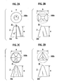
- a base face 2M of the fine protrusion 2 is smaller in size than the wavelength ⁇ of the incident electromagnetic wave. More specifically, in the case of the truncated cone, a diameter D of a circle 100a of the base face 2M of the fine protrusion 2 is smaller than the wavelength ⁇ of the incident electromagnetic wave (see Fig. 2A ). Likewise, in the case of the truncated pyramid, a diameter D of a circumscribing circle 100b of a base polygon 2M is smaller than the wavelength ⁇ of the incident electromagnetic wave (see Fig. 2B, Fig. 2C and Fig. 2D ).
- the above wavelength ⁇ of the incident electromagnetic wave can bring about the following: On each cross section in a thickness direction of the antireflective structure 1, a refractive index of the electromagnetic wave at each cross section is determined by a presence ratio (i.e., structural material relative to air). The electromagnetic wave's refractive index continuously varied from the air's refractive index to the structural material's refractive index in the thickness direction can bring about antireflectivity of the electromagnetic wave.
- the electromagnetic wave reflected from a flat area (second reflective face 2b - to be described afterward) between the fine protrusions 2 is offset by the electromagnetic wave reflected at the head end part 2L, thereby further lowering the reflection.
- the head end part 2L which is flat and smooth is unlikely to be scratched even when causing friction or having a contact with other members, thus minimizing an influence on the antireflectivity, to thereby meet both the electromagnetic wave antireflectivity and the scratchproof.
- the size of the fine protrusion 2 is to be set forth.
- the diameter D of the base face 2M meets D ⁇ ⁇ (wavelength of incident electromagnetic wave).
- D ⁇ 380 nm is preferred for antireflection of a visible light.
- D ⁇ 250 nm is preferred.
- D ⁇ 150 nm is preferred for antireflection of ultraviolet ray while D ⁇ 780 nm is preferred for antireflection of near-infrared ray.
- the diameter D of the base face 2M more than or equal to the wavelength ⁇ of the electromagnetic wave cannot make the pitch P (between adjacent fine protrusions 2) shorter than the wavelength ⁇ , thus causing diffraction of the electromagnetic wave, failing to accomplish the antireflection.
- the diameter D of the circumscribing circle 100b of the polygon is defined as the size of the base face 2M.
- a first occupancy Rt of a first reflective face 2t, a second occupancy Rb of a second reflective face 2b between the fine protrusions 2, and a height H of the fine protrusion 2 are essential.
- Each of the first occupancy Rt and the second occupancy Rb is sampled as a single repetitive unit of the antireflective structures 1.
- the first reflective face 2t is defined as a flat area at the head end part 2L of the fine protrusion 2, while the second reflective face 2b is formed on a base end side of the fine protrusion 2 and defined as a flat area between the adjacent fine protrusions 2.
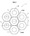
- the first occupancy Rt is defined as a ratio which is the first reflective face 2t's area relative to a unit area (in Fig. 3 , an area of a single unit forming a hexagon).
- the second occupancy Rb is defined as a ratio which is the second reflective face 2b's area relative to the above unit area forming the hexagon.
- a ratio Rt/Rb (first occupancy Rt relative to second occupancy Rb) of 0.2 to 2.0 can improve the antireflectivity of the electromagnetic wave.
- the ratio Rt/Rb of 0.5 to 1.6 is more preferable.
- the shape of the head end part 2L of the fine protrusion 2 is not specifically limited and therefore is not necessarily a complete flat face. In other words, dent, bulge or irregularity each of which is within a height of 20 nm do not influence the reflectivity.
- the height H of the fine protrusion 2 causes the greatest effect when the reflective electromagnetic wave at the head end part 2L is shifted by p/2 from the reflective electromagnetic wave from the second reflective face 2b between the fine protrusions 2 so as to offset the incident electromagnetic wave.
- An arbitrary value A within a range of 0.6 to 1.4 is preferable, and more preferably 0.8 to 1.2.
- the above average refractive index n is defined as a refractive index to the wavelength ⁇ of the incident electromagnetic wave.
- the height H of the fine protrusion 2 is small, making it impossible for the reflective electromagnetic wave from the first and second reflective faces 2t, 2b to make a lower reflection within a target wavelength.
- the lowest reflectivity at around 540 nm to 560 nm which is a wavelength range causing high sensitivity to the human eye.
- the height H's range which is variable with the types of electromagnetic waves may be the one calculated by the above expression (1), preferably, however, the height H is in a range of 80 nm to 160 nm for the range of the ultraviolet ray, 160 nm to 350 nm for the range of the visible light (more preferably, 160 nm to 240 nm) and 350 nm to 45 ⁇ m for the range of the infrared ray.
- the above average refractive index n is defined as the one obtained by averaging the refractive indexes from the head end part 2L of the fine protrusion 2 to the base face 2M (base end part or bottom) of the fine protrusion 2.
- the single unit fine protrusion 2 is divided into 100 pieces in a direction perpendicular to the direction of the height H of the fine protrusion 2 and then a refractive index is to be calculated from a ratio (solid relative to space) of the single unit, followed by averaging of the thus calculated refractive indexes.
- the fine protrusion 2 of the antireflective structure 1 of the present invention is truncated, specifically in Fig. 1 , shaped into a truncated cone.
- the fine protrusion 2 of the present invention may have a configuration of an imprecise truncated cone (i.e., having a curved generating line) or an imprecise truncated pyramid (i.e, having curved side faces), as long as the above imprecise truncated fine protrusion 2 has a cross section becoming gradually smaller from the base face 2M to the head end part 2L.
- a center line 12 connecting a first center O1 of the head end part 2L to a second center 02 of the base face 2M is not necessarily perpendicular to the base face 2M, otherwise may be inclined relative to the base face 2M (see also Fig. 4 to be described afterward).
- a ridge line 11 of the fine protrusion 2 connects an upper base with a lower base of a ladder-shaped (trapezoid) cross section which is perpendicular to the base face 2M and passes through a gravity center (i.e., first center O1) of the head end part 2L of the fine protrusion 2.
- the value X may be corrected by adding a constant
- Fig. 3 also shows a diameter d (head size d) of the head end part 2L.
- the shape of the base face 2M of the fine protrusion 2 may be any of the followings:
- the circle, quadrangle and hexagon are preferable since they are comparatively easy to produce and can be arranged in a packed manner.
- the diameter D is defined as the size of the base face 2M. More specifically, the diameter D is categorized as follows depending on shape of the base face 2M:
- the fine protrusions 2 each having the circular base face 2M can be arranged in a packed manner.
- the base face 2M of the fine protrusions 2 having any of the following shapes needs to be arranged in such a manner as to define gaps therebetween: an equilateral triangle, an equilateral square and an equilateral hexagon each of which allows the base faces 2M to be arranged on a flat face without gaps.
- Materials of the fine protrusion 2 may be basically the same as those of a substrate 201 to be described afterward. In view of improving the antireflectivity as well as durability, however, the fine protrusion 2 is preferably made of the following materials:
- the inorganic oxide-based particles are especially preferable due to:
- Shape of the above particles is not specifically limited, examples thereof including perfect sphere, rugby ball, kompeito (Japanese confectionery having protrusions), indeterminate form, porosity and the like.
- the particle too small in size is less likely to be exposed to the surface and causes increased resin wear. Meanwhile, the participle too large in size is less likely to enter the fine protrusion 2 during molding. In sum, too small or too large in size of the particle cannot improve durability of the fine protrusion 2.
- particles each having a diameter in a range of 10 nm to 50 nm (by sphericity conversion) is preferable, and more preferably 10 nm to 20 nm.
- Strength (compression strength) of the particle is preferably greater than or equal to 500 MPa. Compression strength less than 500 MPa, as the case may be, leads to wear and thereby decreases particle portion, thus failing to secure durability.
- the amount of added particles is preferably in a range of 20 weight % to 60 weight %.
- the antireflective structure 1 of the present invention is to be molded on a first face 201A or preferably on first and second faces 201A, 201B (both faces) of a substrate 201 (or a transparent substrate 201 in the case of visible light), to thereby form an antireflective molded body 200.
- the thus formed antireflective molded body 200 is applied to i) panels of various displays, ii) show windows and iii) transparent panels of exhibition cases, to thereby decrease reflection of an external light or of a room illumination, thus effectively preventing reflective images from being imaged in. As such, visibility (visual recognition) of image, display, room exhibit can be improved.
- antireflective molded body 200 can bring about like antireflectivity, specific examples of the various parts including: i) glasses of window or roof, ii) meter front cover, iii) head lamp, iv) rear finisher, v) film for frontmost face of display such as liquid crystal, and the like.
- Fig. 5 also shows an automobile component 300 to which the antireflective molded body 200 is applied.
- the antireflective molded body 200 of the present invention can be produced by the following operations:
- an active energy line setting resin intervened between the forming die and the substrate 201 irradiating an active energy line so as to set the resin can form the antireflective structure 1 on the surface (i.e., first face 201A) of the substrate 201, thereby forming the antireflective molded body 200.
- materials of the substrate 201 typically have transparency, examples of the materials including:
- examples of the active energy line setting resins which initiates polymerization by an irradiation of rays such as ultraviolet ray so as to be set include: ultraviolet ray setting acryl urethane resin, ultraviolet ray setting polyester acrylate resin, ultraviolet ray setting epoxy acrylate resin, ultraviolet ray setting polyol acrylate resin, ultraviolet ray setting epoxy resin and the like.
- typical examples of the active energy line include ultraviolet ray, X-ray, other electron beams or electromagnetic waves and the like, but not specifically limited thereto.
- an inorganic transparent material such as glass and the like may be used for the substrate 201.
- the antireflective structure 1 can be formed on the surface (i.e., first face 201 A) of the substrate 201 by the following operations:
- a mold developed by a commercial electron beam drawing device was used. The mold was heated to 170° C. Then, 10 MPa of a pressure was applied to first and second faces 201A, 201B (both faces) of a polycarbonate ("PC" for short) substrate 201 for 1 hr, followed by cooling at less than or equal to 70° C, to thereby prepare an antireflective molded body 200 having both faces each formed with the antireflective structure 1 where the fine protrusions 2 are arranged in a hexagonal packed structure (pitch P: 1000 nm), as shown in Table 1.
- Each of the fine protrusions 2 has the following specifications: 1) Overall configuration Truncated cone 2) Diameter D of base face 2M: 1000 nm 3) Diameter d of head end face 2L: 250 nm 4) Height H: 750 nm
- the thus prepared antireflective molded body 200 was subjected to an irradiation of an infrared ray having a wavelength of 2000 nm, so as to measure reflectivity at an incident angle of 0 degree and a measurement angle of 0 degree, to thereby evaluate antireflectivity.
- a surface of the antireflective molded body 200 was subjected to 5000 wiping operations (round trips, i.e., reciprocations) with a face pressure of 392 Pa, and then was subjected to a visual test for checking for scratches (scratchproof test).
- a mold developed by a like electron beam drawing device was used. Operations like those of the example 1 were repeated, to thereby prepare an antireflective molded body 200 including a polymethyl methacrylate ("PMMC" for short) substrate 201 having first and second faces 201A, 201B each formed with the antireflective structure 1 where the fine protrusions 2 are arranged in a hexagonal packed structure (pitch P: 300 nm), as shown in Table 1.
- PMMC polymethyl methacrylate
- the thus prepared antireflective molded body 200 was subjected to an irradiation of a visible light having a wavelength of 555 nm, so as to measure reflectivity at an incident angle of 0 degree and a measurement angle of 0 degree, to thereby evaluate antireflectivity.
- Table 2 shows results of the antireflectivity and scratchproof tests.
- an antireflective molded body 200 including a polymethyl methacrylate substrate 201 having first and second faces 201 A, 201B each formed with the antireflective structure 1 where the fine protrusions 2 are arranged in a hexagonal packed structure, as shown in Table 1.
- Each of the fine protrusions 2 has the following specifications:
- each of the thus prepared antireflective molded bodies 200 was subjected to the evaluations on reflectivity and scratchproof in a manner like that of the example 2.
- Table 2 shows results of the antireflectivity and scratchproof tests.
- an antireflective molded body 200 including a polymethyl methacrylate substrate 201 having first and second faces 201A and 201B each formed with the antireflective structure 1 where the fine protrusions 2 are arranged in a hexagonal packed structure, as shown in Table 1.
- Each of the fine protrusions 2 has the following specifications:
- each of the thus prepared antireflective molded bodies 200 was subjected to the evaluations on reflectivity and scratchproof in a manner like that of the example 2.
- Table 2 shows results of the antireflectivity and scratchproof tests.
- Toluene dispersed silica sol (sphericity conversion particle diameter: 30 nm, compression strength of particle: 6.2 GPa, concentration: 20 % solution) was mixed into 70 mass % of UV (ultraviolet) setting acrylic resin (polymethyl methacrylate) and 10 mass % of ⁇ methacryloxy propyl trimethoxy silane, such that solid content becomes 30 weight %. Then, the mixture was applied to a polymethyl methacrylate substrate 201 in such a manner as to form a film thickness of 50 ⁇ m.
- UV ultraviolet
- the mold same as that prepared in the example 1 was pressed on the surface of the film, followed by an ultraviolet ray irradiation for 10 minutes using a high pressure mercury lamp (80 W), to thereby prepare an antireflective molded body 200 including the antireflective structure 1 where the fine protrusions 2 made of resin and silica particle are arranged in a hexagonal packed structure, as shown in Table 1.
- Each of the fine protrusions 2 has the following specifications:
- the thus prepared antireflective molded body 200 was subjected to the evaluations on reflectivity and scratchproof in a manner like that of the example 1.
- Table 2 shows results of the antireflectivity and scratchproof tests.
- the thus prepared antireflective molded body 200 was subjected to the evaluations on reflectivity and scratchproof in a manner like that of the example 2.
- Table 2 shows results of the antireflectivity and scratchproof tests.
- an antireflective molded body 200 including a polymethyl methacrylate substrate 201 having first and second faces 201 A, 201B each formed with the antireflective structure 1 where the fine protrusions 2 are arranged in a hexagonal packed structure (pitch P: 200 nm), as shown in Table 1.
- P pitch P: 200 nm
- the thus prepared antireflective molded body 200 was subjected to the evaluations on reflectivity and scratchproof in a manner like that of the example 2.
- Table 2 shows results of the antireflectivity and scratchproof tests.
- PC denotes polycarbonate and PMMC denotes polymethyl methacrylate Section Incident wavelength ⁇ (nm)
- Substrate 201 Configuration and sizes of fine protrusion 2 Material Refractive index n Diameter D (nm) Diameter d (nm) Height H (nm) Arbitrary value
- n Diameter D
- nm Diameter d
- H (nm)
- Arbitrary value A First occupancy Rt Second occupancy Rb Ratio Rt/Rb Order m ⁇ of ridge line 11's linear expression (2) ⁇
- Example 1 2000 PC 1.20 1000 250 750 0.900 0.0567 0.0936 0.606 1 (straight)
- Example 2 555 PMMC 1.18 300 45 220 0.935 0.0204 0.0936 0.218 1 (straight)
- Example 3 555 PMMC 1.19 250 50 160 0.686 0.0363 0.0936 0.388 1 (straight)
- Example 4 555 PMMC 1.
- each of the examples 1 to 11 of the present invention shows a low reflectivity to the incident electromagnetic wave.
Landscapes
- Physics & Mathematics (AREA)
- General Physics & Mathematics (AREA)
- Optics & Photonics (AREA)
- Surface Treatment Of Optical Elements (AREA)
Abstract
Description
- The present invention relates to an antireflective structure which is excellent in electromagnetic wave antireflectivity as well as scratchproof.
- The present invention also relates to an antireflective molded body which includes the above antireflective structure and is preferably used as a non-reflective panel for bodies, various meters, displays and the like of vehicles (automobiles), ships, aircrafts and the like.
- In such fields as aircrafts, automobiles, ships and the like, antireflection of electromagnetic wave is necessary for such applications as: i) stealth technology not viewed on radar, ii) an IR measurement camera, a meter cover, a liquid crystal display which are used for measuring vehicle-to-vehicle distance, and the like.
- For example, a driver's seat of an automobile has a meter front cover which is embedded in a front face of a display where various meters such as speedometer, fuel meter and the like are received in combination. In this case, however, the scenery outside the vehicle is imaged in through a front window or a side window to the meter front cover, as the case may be, making it difficult to view the various meters of the display. For preventing the above invisibility, a meter hood is disposed above the various meters for blocking an external light from entering the meter display.
- A structure including a plurality of thin films having different refractive indexes are conventionally known as a multilayer antireflective film which is used for preventing reflection of the light as stated above.
- Japanese Patent Application Laid-Open No.
2002-267815 JP2002267815 -
JP2002267815 - When a myriad of fine irregularities (fine protrusions and dents) each of which is corrugated or triangular in cross section are formed on the surface, occupancy (ratio of presence) of the transparent material on the outermost surface of the irregularities is limitlessly closer to 0%, which is a state substantially causing a refractive index of air.
- Meanwhile, at the base face of the irregularities, occupancy of the air is limitlessly closer to 0%, which is a state substantially causing a refractive index of the transparent material.
- Furthermore, an intermediary part of the irregularities has an refractive index according to the cross section occupied by the transparent material.
- As such, the refractive index of light continuously varies between the refractive index of air and the refractive index of transparent material in the thickness direction of the antireflective structure.
- As a result, according to a principle like that of the multilayer antireflective film having a plurality of thin films with different refractive indexes which vary stepwise, the antireflective structure of
JP2002267815 - However,
JP2002267815 - It is an object of the present invention to provide an antireflective structure capable of improving antireflectivity of an electromagnetic wave and preventing damage to a head end part of each of fine protrusions of irregularities by optimizing shape of the head end part. In other words, the object of the present invention is to provide the antireflective structure having both antireflectivity and scratchproof.
- According to a first aspect of the present invention, an antireflective structure comprises: a substantially flat layer having a surface; a fine structure layer including: a myriad of truncated fine protrusions each including: a head end part, and a base face which is at least one of: a substantially circular base face of a truncated cone, the circular base face having a diameter D of a circle, and a substantially polygonal base face of a truncated pyramid, the polygonal base face having a diameter D of a circumscribing circle of the polygonal base face, the truncated fine protrusions being arranged on the surface of the flat layer in such a manner as to define a pitch, wherein, with a first reflective face formed in the head end part of each of the truncated fine protrusions, and a second reflective face formed between the truncated fine protrusions on the surface of the flat layer: each of the diameter D of the circle and the diameter D of the circumscribing circle is smaller than a wavelength λ of an incident electromagnetic wave, and the pitch is smaller than the wavelength λ of the incident electromagnetic wave.
- According to a second aspect of the present invention, an antireflective structure comprises: a myriad of truncated fine protrusions each including: a head end part, and a base face which is at least one of: a substantially circular base face of a truncated cone, the circular base face having a diameter D of a circle, and a substantially polygonal base face of a truncated pyramid, the polygonal base face having a diameter D of a circumscribing circle of the polygonal base face, the truncated fine protrusions being arranged on a surface in such a manner as to define a pitch, wherein, with a first reflective face formed in the head end part of each of the truncated fine protrusions, and a second reflective face formed between the truncated fine protrusions on a base end side of the fine protrusions: each of the diameter D of the circle and the diameter D of the circumscribing circle is smaller than a wavelength λ of an incident electromagnetic wave, and the pitch is smaller than the wavelength λ of the incident electromagnetic wave.
- According to a third aspect of the present invention, an antireflective molded body comprises: a substrate having a first face and a second face; and the antireflective structure according to the first aspect, wherein the antireflective structure is provided on at least one of the first face and the second face.
- According to a fourth aspect of the present invention, an automobile component comprises: the antireflective molded body according to the third aspect.
- Other objects and features of the present invention will become understood from the following description with reference to the accompanying drawings.
-
-
Fig. 1 is a perspective view of an antireflective structure of the present invention. -
Fig. 2A to Fig. 2D each show an example of a fine protrusion of the antireflective structure under the present invention,
where -
Fig. 2A is a first example showing that the fine protrusion is shaped into a truncated cone, -
Fig. 2B is a second example showing that the fine protrusion is shaped into a truncated rectangular pyramid, -
Fig. 2C is a third example showing that the fine protrusion is shaped into a truncated hexagonal pyramid, and -
Fig. 2D is a fourth example showing that the fine protrusion is shaped into a truncated triangular pyramid. -
Fig. 3 is a plan view of the antireflective structure for explaining a first occupancy which is an occupancy of a first reflective face of a head end part and a second occupancy which is an occupancy of a second reflective face between the adjacent fine protrusions. -
Fig. 4 shows a graph of an m-order linear expression for expressing configuration of a ridge line of the fine protrusion of the antireflective structure under the present invention. -
Fig. 5 shows an antireflective molded body and an automobile component to which the antireflective molded body is applied, under the present invention. - In the following, various embodiments of the present invention will be described in detail with reference to the accompanying drawings.
- For ease of understanding, the following description will contain various directional terms, such as left, right, upper, lower, forward, rearward and the like. However, such terms are to be understood with respect to only a drawing or drawings on which the corresponding part of element is illustrated.
- Hereinafter, an antireflective structure and an antireflective molded body to which the antireflective structure including a fine structure layer is applied are to be set forth in detail, together with methods of producing the antireflective structure and antireflective molded body and referring to embodiments and examples.
- The antireflective structure of the present invention includes a myriad of fine protrusions each of which is shaped into a truncated cone or a truncated pyramid.
- In the antireflective structure, each of i) a head end part of the fine protrusion and ii) an area between the truncated fine protrusions has a reflective face (2t, 2b). A base face of the fine protrusion is smaller in size than a wavelength of an incident electromagnetic wave. In addition, the fine protrusions are arranged such that a pitch of the fine protrusion is smaller in size than the above wavelength.
-
Fig. 1 shows anantireflective structure 1, according to a first embodiment of the present invention. In theantireflective structure 1 of the present invention, a myriad offine protrusions 2 each having a flathead end part 2L and shaped substantially into a truncated cone or a truncated pyramid (truncated cone inFig. 1 according to the first embodiment) are arranged such that a pitch P of thefine protrusion 2 is smaller than a wavelength λ of an incident electromagnetic wave. Thefine protrusions 20 form afine structure layer 20.Fig. 1 also shows aflat layer 30 having asurface 30A on which thefine protrusions 2 are disposed. Hereinabove, abase face 2M of thefine protrusion 2 is smaller in size than the wavelength λ of the incident electromagnetic wave. More specifically, in the case of the truncated cone, a diameter D of acircle 100a of thebase face 2M of thefine protrusion 2 is smaller than the wavelength λ of the incident electromagnetic wave (seeFig. 2A ). Likewise, in the case of the truncated pyramid, a diameter D of acircumscribing circle 100b of abase polygon 2M is smaller than the wavelength λ of the incident electromagnetic wave (seeFig. 2B, Fig. 2C and Fig. 2D ). - The above wavelength λ of the incident electromagnetic wave can bring about the following: On each cross section in a thickness direction of the
antireflective structure 1, a refractive index of the electromagnetic wave at each cross section is determined by a presence ratio (i.e., structural material relative to air). The electromagnetic wave's refractive index continuously varied from the air's refractive index to the structural material's refractive index in the thickness direction can bring about antireflectivity of the electromagnetic wave. - Meanwhile, since the
head end part 2L of each of thefine protrusions 2 is flattened, the electromagnetic wave reflected from a flat area (secondreflective face 2b - to be described afterward) between thefine protrusions 2 is offset by the electromagnetic wave reflected at thehead end part 2L, thereby further lowering the reflection. - Moreover, the
head end part 2L which is flat and smooth is unlikely to be scratched even when causing friction or having a contact with other members, thus minimizing an influence on the antireflectivity, to thereby meet both the electromagnetic wave antireflectivity and the scratchproof. - Hereinafter, the size of the
fine protrusion 2 is to be set forth. InFig. 2A showing thefine protrusion 2 shaped into the truncated cone, the diameter D of thebase face 2M meets D < λ (wavelength of incident electromagnetic wave). Especially, D ≤ 380 nm is preferred for antireflection of a visible light. From the viewpoint of preventing the reflective light's coloration which may be caused by diffraction, D ≤ 250 nm is preferred. In addition, D ≤ 150 nm is preferred for antireflection of ultraviolet ray while D ≤ 780 nm is preferred for antireflection of near-infrared ray. - In sum, the diameter D of the
base face 2M more than or equal to the wavelength λ of the electromagnetic wave cannot make the pitch P (between adjacent fine protrusions 2) shorter than the wavelength λ, thus causing diffraction of the electromagnetic wave, failing to accomplish the antireflection. - Moreover, in the case of the truncated pyramids as shown in
Fig. 2B (rectangular),Fig. 2C (hexagonal) andFig. 2D (triangular), the diameter D of the circumscribingcircle 100b of the polygon is defined as the size of thebase face 2M. - Under the present invention, for offsetting i) the electromagnetic wave reflected at the
head end part 2L by ii) the reflective electromagnetic wave caused from the flat area (secondreflective face 2b) between thefine protrusions 2, a first occupancy Rt of a firstreflective face 2t, a second occupancy Rb of a secondreflective face 2b between thefine protrusions 2, and a height H of thefine protrusion 2 are essential. - Each of the first occupancy Rt and the second occupancy Rb is sampled as a single repetitive unit of the
antireflective structures 1. - Specifically, in
Fig. 3 showing a plan view of theantireflective structure 1, the firstreflective face 2t is defined as a flat area at thehead end part 2L of thefine protrusion 2, while the secondreflective face 2b is formed on a base end side of thefine protrusion 2 and defined as a flat area between the adjacentfine protrusions 2. - The first occupancy Rt is defined as a ratio which is the first
reflective face 2t's area relative to a unit area (inFig. 3 , an area of a single unit forming a hexagon). Meanwhile, the second occupancy Rb is defined as a ratio which is the secondreflective face 2b's area relative to the above unit area forming the hexagon. - With the
antireflective structure 1 of the present invention, a ratio Rt/Rb (first occupancy Rt relative to second occupancy Rb) of 0.2 to 2.0 can improve the antireflectivity of the electromagnetic wave. The ratio Rt/Rb of 0.5 to 1.6 is more preferable. - As long as the above ranges of the ratio Rt/Rb are met, the shape of the
head end part 2L of thefine protrusion 2 is not specifically limited and therefore is not necessarily a complete flat face. In other words, dent, bulge or irregularity each of which is within a height of 20 nm do not influence the reflectivity. - Then, the height H of the
fine protrusion 2 causes the greatest effect when the reflective electromagnetic wave at thehead end part 2L is shifted by p/2 from the reflective electromagnetic wave from the secondreflective face 2b between thefine protrusions 2 so as to offset the incident electromagnetic wave. - Specifically, the height H is given by the following expression (1):

- An arbitrary value A within a range of 0.6 to 1.4 is preferable, and more preferably 0.8 to 1.2. The above average refractive index n is defined as a refractive index to the wavelength λ of the incident electromagnetic wave.
- When A < 0.6, the height H of the
fine protrusion 2 is small, making it impossible for the reflective electromagnetic wave from the first and secondreflective faces - When A > 1.4, the height H of the
fine protrusion 2 is large, thus calming the refractive index change. In this case, the antireflection can be secured to a certain extent, while the scratchproof is likely to be deteriorated. - Especially, for the purpose of antireflection of the visible light, it is preferred to design the lowest reflectivity at around 540 nm to 560 nm which is a wavelength range causing high sensitivity to the human eye.
- The height H's range which is variable with the types of electromagnetic waves may be the one calculated by the above expression (1), preferably, however, the height H is in a range of 80 nm to 160 nm for the range of the ultraviolet ray, 160 nm to 350 nm for the range of the visible light (more preferably, 160 nm to 240 nm) and 350 nm to 45 µm for the range of the infrared ray.
- In addition, the above average refractive index n is defined as the one obtained by averaging the refractive indexes from the
head end part 2L of thefine protrusion 2 to thebase face 2M (base end part or bottom) of thefine protrusion 2. - For calculating the average refractive index n, the single unit
fine protrusion 2 is divided into 100 pieces in a direction perpendicular to the direction of the height H of thefine protrusion 2 and then a refractive index is to be calculated from a ratio (solid relative to space) of the single unit, followed by averaging of the thus calculated refractive indexes. - As set forth above, the
fine protrusion 2 of theantireflective structure 1 of the present invention is truncated, specifically inFig. 1 , shaped into a truncated cone. However, not only having a configuration of a precise truncated cone (i.e., having a straight generating line) or a precise truncated pyramid (i.e., having a straight ridge line and flat side faces), thefine protrusion 2 of the present invention may have a configuration of an imprecise truncated cone (i.e., having a curved generating line) or an imprecise truncated pyramid (i.e, having curved side faces), as long as the above imprecise truncatedfine protrusion 2 has a cross section becoming gradually smaller from thebase face 2M to thehead end part 2L. - Moreover, a
center line 12 connecting a first center O1 of thehead end part 2L to asecond center 02 of thebase face 2M is not necessarily perpendicular to thebase face 2M, otherwise may be inclined relative to thebase face 2M (see alsoFig. 4 to be described afterward). - As such, not only the precise truncated cone or precise truncated pyramid, the language "truncated" of the present invention includes the following shapes:
- 1) a modified cone (such as bell shape or acorn shape) so configured as to have a flat head end part,
- 2) a modified cone (such as bell shape or acorn shape) so configured as to have an inclined head end part,
- 3) a modified pyramid (having curved side faces) so configured to have a flat head end part, and
- 4) a modified pyramid (having curved side faces) so configured as to have an inclined head end part.
- A
ridge line 11 of thefine protrusion 2 connects an upper base with a lower base of a ladder-shaped (trapezoid) cross section which is perpendicular to thebase face 2M and passes through a gravity center (i.e., first center O1) of thehead end part 2L of thefine protrusion 2. - It is preferable that the
ridge line 11 has a configuration given by the following linear expression (2) as shown inFig. 4 :
- With this, change ratio of the refractive indexes n from an apex 10 (imaginary) of the
fine protrusion 2 to thebase face 2M of thefine protrusion 2 becomes constant, thus more improving the antireflectivity. - In the linear expression (2):
- an X-axis is defined on the base side (
base face 2M) in the cross section which is perpendicular to thebase face 2M and passes through the first center O1 and thesecond center 02 which are connected by thecenter line 12, - "m" denotes an order (1 ≤ m≤ 1.5),
- "h" denotes a height from the
base face 2M to the apex 10 which is an intersection of an extension of thecenter line 12 with an extension of theridge line 11 and is disposed on a Z-axis. - In this case, depending on the position of the apex 10, the value X may be corrected by adding a constant
-
Fig. 3 also shows a diameter d (head size d) of thehead end part 2L. - Moreover, the shape of the
base face 2M of thefine protrusion 2 may be any of the followings: - 1) substantially circular shape such as circle, ellipse and oval,
- 2) polygons such as triangle, quadrangle, pentagon, hexagon, and
- 3) an intermediary shape between circle and polygon, which shape having outwardly swollen sides of polygons.
- Among the above, the circle, quadrangle and hexagon are preferable since they are comparatively easy to produce and can be arranged in a packed manner.
- In addition, with the
fine protrusion 2 as set forth above, it is the diameter D that is defined as the size of thebase face 2M. More specifically, the diameter D is categorized as follows depending on shape of thebase face 2M: - 1)
circular base face 2M: diameter D - 2) elliptical or
oval base face 2M: diameter of a longer (major) axis - 3)
polygonal base face 2M: diameter D circumscribing the polygon - From the viewpoint of forming the second
reflective face 2b on a base end side (i.e.,base face 2M) of the fine protrusion 2 (seeFig. 3 ), thefine protrusions 2 each having thecircular base face 2M can be arranged in a packed manner. - Contrary to the above, the
base face 2M of thefine protrusions 2 having any of the following shapes needs to be arranged in such a manner as to define gaps therebetween: an equilateral triangle, an equilateral square and an equilateral hexagon each of which allows the base faces 2M to be arranged on a flat face without gaps. - Materials of the
fine protrusion 2 may be basically the same as those of asubstrate 201 to be described afterward. In view of improving the antireflectivity as well as durability, however, thefine protrusion 2 is preferably made of the following materials: - i) resin (to be described afterward), and
- ii) particles each having a diameter in a range of 10 nm to 50 nm (by sphericity conversion).
- The above particles are not specifically limited, examples thereof including:
- 1) organic particles such as polymethyl methacrylate, polystyrene, amide, imide, polyester and the like,
- 2) inorganic oxide-based particles such as silicon dioxide, titanium dioxide, zirconium dioxide, aluminium oxide and the like,
- 3) metallic colloidal particles such as gold, silver, platinum, iron and the like,
- 4) ceramic-based particles such as barium titanate.
- For improving durability of the
fine protrusion 2, the inorganic oxide-based particles are especially preferable due to: - i) having a high compression strength, and
- ii) featuring a good adhesion to resin by reforming the surface of the particle.
- Shape of the above particles is not specifically limited, examples thereof including perfect sphere, rugby ball, kompeito (Japanese confectionery having protrusions), indeterminate form, porosity and the like.
- The particle too small in size is less likely to be exposed to the surface and causes increased resin wear. Meanwhile, the participle too large in size is less likely to enter the
fine protrusion 2 during molding. In sum, too small or too large in size of the particle cannot improve durability of thefine protrusion 2. As such, particles each having a diameter in a range of 10 nm to 50 nm (by sphericity conversion) is preferable, and more preferably 10 nm to 20 nm. - Strength (compression strength) of the particle is preferably greater than or equal to 500 MPa. Compression strength less than 500 MPa, as the case may be, leads to wear and thereby decreases particle portion, thus failing to secure durability.
- Too small an amount of added particles cannot improve durability of the
fine protrusion 2, leading to a fragile molded product (casting); while too large an amount of added particles may deteriorate dispersion of the particles, leading to a deteriorated transparency. As such, the amount of added particles is preferably in a range of 20 weight % to 60 weight %. - As shown in
Fig. 5 , theantireflective structure 1 of the present invention is to be molded on afirst face 201A or preferably on first andsecond faces transparent substrate 201 in the case of visible light), to thereby form an antireflective moldedbody 200. The thus formed antireflective moldedbody 200 is applied to i) panels of various displays, ii) show windows and iii) transparent panels of exhibition cases, to thereby decrease reflection of an external light or of a room illumination, thus effectively preventing reflective images from being imaged in. As such, visibility (visual recognition) of image, display, room exhibit can be improved. - Moreover, applying the above antireflective molded
body 200 to various components including those for automobiles can bring about like antireflectivity, specific examples of the various parts including: i) glasses of window or roof, ii) meter front cover, iii) head lamp, iv) rear finisher, v) film for frontmost face of display such as liquid crystal, and the like. -
Fig. 5 also shows anautomobile component 300 to which the antireflective moldedbody 200 is applied. - The antireflective molded
body 200 of the present invention can be produced by the following operations: - 1) preparing a forming die having fine dents which are a counterpart (converted shape) of a myriad of
fine protrusions 2 as set forth above, - 2) pressing the forming die and the
substrate 201 to each other in a state that at least one of the forming die and thesubstrate 201 is heated, and - 3) forming the
antireflective structure 1 on a surface (i.e.,first face 201A) of thesubstrate 201. - In addition, with an active energy line setting resin intervened between the forming die and the
substrate 201, irradiating an active energy line so as to set the resin can form theantireflective structure 1 on the surface (i.e.,first face 201A) of thesubstrate 201, thereby forming the antireflective moldedbody 200. - Preferably, materials of the
substrate 201 typically have transparency, examples of the materials including: - 1) thermoplastic resins such as polyethylene, polypropylene, polyvinyl alcohol, polyvinylidene chloride, polyethylene terephthalate, polyvinyl chloride, polystyrene, ABS resin, AS resin, acrylic resin, polyamide, polyacetal, polybutylene terephthalate, glass-reinforced polyethylene terephthalate, polycarbonate, modified polyphenylene ether, polyphenylene sulfide, polyetherether ketone, liquid crystalline polymer, fluorine resin, polyallate, polysulfone, polyethersulfone, polyamideimide, polyetherimide, thermoplastic polyimide and the like,
- 2) thermosetting resins such as phenol resin, melamine resin, urea resin, epoxy resin, unsaturated polyester resin, alkyd resin, silicone resin, diallyl phthalate resin, polyamide bismaleimide, polybisamide triazole and the like, and
- 3) a blend of two or more of the above.
- Moreover, examples of the active energy line setting resins which initiates polymerization by an irradiation of rays such as ultraviolet ray so as to be set include: ultraviolet ray setting acryl urethane resin, ultraviolet ray setting polyester acrylate resin, ultraviolet ray setting epoxy acrylate resin, ultraviolet ray setting polyol acrylate resin, ultraviolet ray setting epoxy resin and the like.
- If necessary:
- 1) polymerization initiator for causing radials by irradiating the active energy line may be used, and
- 2) setting agent such as isocyanate for setting the resin more solidly may be added.
- Hereinabove, typical examples of the active energy line include ultraviolet ray, X-ray, other electron beams or electromagnetic waves and the like, but not specifically limited thereto.
- In addition, an inorganic transparent material such as glass and the like may be used for the
substrate 201. - In this case, the
antireflective structure 1 can be formed on the surface (i.e.,first face 201 A) of thesubstrate 201 by the following operations: - 1) cutting a surface of the glass by means of an electron beam or the like.
- 2) flowing a melted inorganic transparent material into a mold having a configuration of the
antireflective structure 1 of the present invention. - Hereinafter, the present invention is to be set forth more in detail referring to examples. It is needless to say, however, that the present invention is not limited to the examples.
- A mold developed by a commercial electron beam drawing device was used. The mold was heated to 170° C. Then, 10 MPa of a pressure was applied to first and
second faces substrate 201 for 1 hr, followed by cooling at less than or equal to 70° C, to thereby prepare an antireflective moldedbody 200 having both faces each formed with theantireflective structure 1 where thefine protrusions 2 are arranged in a hexagonal packed structure (pitch P: 1000 nm), as shown in Table 1. Each of thefine protrusions 2 has the following specifications:1) Overall configuration Truncated cone 2) Diameter D of base face 2M:1000 nm 3) Diameter d of head end face 2L:250 nm 4) Height H: 750 nm - Then, the thus prepared antireflective molded
body 200 was subjected to an irradiation of an infrared ray having a wavelength of 2000 nm, so as to measure reflectivity at an incident angle of 0 degree and a measurement angle of 0 degree, to thereby evaluate antireflectivity. - Then, a surface of the antireflective molded
body 200 was subjected to 5000 wiping operations (round trips, i.e., reciprocations) with a face pressure of 392 Pa, and then was subjected to a visual test for checking for scratches (scratchproof test). - Scratchproof test criteria:
Table 2 shows results of the antireflectivity and scratchproof tests. Scratch visually found: Rejected Scratch visually not found: Accepted - A mold developed by a like electron beam drawing device was used. Operations like those of the example 1 were repeated, to thereby prepare an antireflective molded
body 200 including a polymethyl methacrylate ("PMMC" for short)substrate 201 having first andsecond faces antireflective structure 1 where thefine protrusions 2 are arranged in a hexagonal packed structure (pitch P: 300 nm), as shown in Table 1. Each of thefine protrusions 2 has the following specifications: - 1) Overall configuration Truncated cone
- 2) Diameter D of
base face 2M: 300 nm - 3) Diameter d of
head end face 2L: 45 nm - 4) Height H: 220 nm
- Then, the thus prepared antireflective molded
body 200 was subjected to an irradiation of a visible light having a wavelength of 555 nm, so as to measure reflectivity at an incident angle of 0 degree and a measurement angle of 0 degree, to thereby evaluate antireflectivity. - Then, the scratchproof test was implemented on a surface of the antireflective molded
body 200 in a manner like that according to the example 1. - Table 2 shows results of the antireflectivity and scratchproof tests.
- Operations like those of the example 2 were repeated, to thereby prepare an antireflective molded
body 200 including apolymethyl methacrylate substrate 201 having first andsecond faces antireflective structure 1 where thefine protrusions 2 are arranged in a hexagonal packed structure, as shown in Table 1. Each of thefine protrusions 2 has the following specifications: - 1) Overall configuration Truncated cone
- 2) Diameter D of
base face 2M: See Table 1 - 3) Diameter d of
head end face 2L: See Table 1 - 4) Height H: See Table 1
- Then, each of the thus prepared antireflective molded
bodies 200 was subjected to the evaluations on reflectivity and scratchproof in a manner like that of the example 2. - Table 2 shows results of the antireflectivity and scratchproof tests.
- Operations like those of the example 2 were repeated, to thereby prepare an antireflective molded
body 200 including apolymethyl methacrylate substrate 201 having first andsecond faces antireflective structure 1 where thefine protrusions 2 are arranged in a hexagonal packed structure, as shown in Table 1. Each of thefine protrusions 2 has the following specifications: - 1) Overall configuration Truncated cone
- 2) Diameter D of
base face 2M: See Table 1 - 3) Diameter d of
head end face 2L: See Table 1 - 4) Height H: See Table 1
- 5)
Ridge line 11 from outer periphery ofhead end face 2L to outer periphery ofbase face 2M: Given by the linear expression (2) with the order m =1.2 (for the example 6) and 1.5 (for the example 7) - Then, each of the thus prepared antireflective molded
bodies 200 was subjected to the evaluations on reflectivity and scratchproof in a manner like that of the example 2. - Table 2 shows results of the antireflectivity and scratchproof tests.
- Toluene dispersed silica sol (sphericity conversion particle diameter: 30 nm, compression strength of particle: 6.2 GPa, concentration: 20 % solution) was mixed into 70 mass % of UV (ultraviolet) setting acrylic resin (polymethyl methacrylate) and 10 mass % of γ methacryloxy propyl trimethoxy silane, such that solid content becomes 30 weight %. Then, the mixture was applied to a
polymethyl methacrylate substrate 201 in such a manner as to form a film thickness of 50 µm. - Then, the mold same as that prepared in the example 1 was pressed on the surface of the film, followed by an ultraviolet ray irradiation for 10 minutes using a high pressure mercury lamp (80 W), to thereby prepare an antireflective molded
body 200 including theantireflective structure 1 where thefine protrusions 2 made of resin and silica particle are arranged in a hexagonal packed structure, as shown in Table 1. Each of thefine protrusions 2 has the following specifications: - 1) Overall configuration Truncated cone
- 2) Diameter D of
base face 2M: See Table 1 - 3) Diameter d of
head end face 2L: See Table 1 - 4) Height H: See Table 1
- Then, the thus prepared antireflective molded
body 200 was subjected to the evaluations on reflectivity and scratchproof in a manner like that of the example 1. - Table 2 shows results of the antireflectivity and scratchproof tests.
- Operations like those of the example 10 were repeated, other than that the toluene dispersed silica sol (sphericity conversion particle diameter: 10 nm, compression strength of particle: 6.2 GPa, concentration: 30 % solution) was used and that the mold same as that in the example 3 was used, to thereby prepare an antireflective molded
body 200 like that of the example 10. - Then, the thus prepared antireflective molded
body 200 was subjected to the evaluations on reflectivity and scratchproof in a manner like that of the example 2. - Table 2 shows results of the antireflectivity and scratchproof tests.
- Operations like those of the example 2 were repeated by using a molded developed by the like electron beam drawing device, to thereby prepare an antireflective molded
body 200 including apolymethyl methacrylate substrate 201 having first andsecond faces antireflective structure 1 where thefine protrusions 2 are arranged in a hexagonal packed structure (pitch P: 200 nm), as shown in Table 1. Each of thefine protrusions 2 has the following specifications: - 1) Overall configuration Cone
- 2) Diameter D of
base face 2M: 200 nm - 3) Diameter d of
head end face 2L: 0 nm (not defined) - 4) Height H: 200 nm
- Then, the thus prepared antireflective molded
body 200 was subjected to the evaluations on reflectivity and scratchproof in a manner like that of the example 2. - Table 2 shows results of the antireflectivity and scratchproof tests.
[Table 1-A] - PC denotes polycarbonate and PMMC denotes polymethyl methacrylate Section Incident wavelength λ (nm) Substrate 201 Configuration and sizes of fine protrusion 2 Material Refractive index n Diameter D (nm) Diameter d (nm) Height H (nm) Arbitrary value A First occupancy Rt Second occupancy Rb Ratio Rt/Rb Order m {of ridge line 11's linear expression (2)} Example 1 2000 PC 1.20 1000 250 750 0.900 0.0567 0.0936 0.606 1 (straight) Example 2 555 PMMC 1.18 300 45 220 0.935 0.0204 0.0936 0.218 1 (straight) Example 3 555 PMMC 1.19 250 50 160 0.686 0.0363 0.0936 0.388 1 (straight) Example 4 555 PMMC 1.23 200 70 200 0.884 0.1110 0.0936 1.187 1 (straight) Example 5 555 PMMC 1.19 100 35 200 0.858 0.1110 0.0936 1.187 1 (straight) [Table 1-B] - PC denotes polycarbonate and PMMC denotes polymethyl methacrylate Section Incident wavelength λ (nm) Substrate 201 Configuration and sizes of fine protrusion 2 Material Refractive index n Diameter D (nm) Diameter d (nm) Height H (nm) Arbitrary value A First occupancy Rt Second occupancy Rb Ratio Rt/Rb Order m {of ridge line 11's linear expression (2)} Example 6 555 PMMC 1.27 200 40 240 1.098 0.0363 0.0936 0.388 1.2 Example 7 555 PMMC 1.24 200 80 240 1.072 0.1450 0.0936 1.550 1.5 Example 8 555 PMMC 1.25 200 90 160 0.721 0.1836 0.0936 1.962 1 (straight) Example 9 555 PMMC 1.21 100 30 320 1.395 0.0816 0.0936 0.872 1 (straight) Example 10 2000 PMMA+ particle 1.17 1000 250 750 0.900 0.0567 0.0936 0.606 1 (straight) Example 11 555 PMMA+ particle 1.19 250 50 160 0.686 0.0363 0.0936 0.388 1 (straight) [Table 1-C] - PC denotes polycarbonate and PMMC denotes polymethyl methacrylate Section Incident wavelength λ (nm) Substrate 201 Configuration and sizes of fine protrusion 2 Material Refractive index n Diameter D (nm) Diameter d (nm) Height H (nm) Arbitrary value A First occupancy Rt Second occupancy Rb Ratio Rt/Rb Order in {of ridge line 11's linear expression (2)} Comparative example 1 555 PMMC 1.17 200 0 200 0.843 0 0.0936 0 1 (straight) [Table 2] Section Performance tests Reflectivity (%) Scratchproof Example 1 0.38 Accepted Example 2 0.45 Accepted Example 3 0.39 Accepted Example 4 0.12 Accepted Example 5 0.12 Accepted Example 6 0.13 Accepted Example 7 0.21 Accepted Example 8 0.38 Accepted Example 9 0.16 Accepted Example 10 0.35 Accepted Example 11 0.38 Accepted Comparative example 1 1.20 Rejected - As a result, it was verified that each of the examples 1 to 11 of the present invention shows a low reflectivity to the incident electromagnetic wave.
- Contrary to the examples 1 to 11 of the present invention, the antireflective structure of the comparative example 1 is weak in antireflectivity as well as scratchproof due to the following: the fine protrusion is conical (not truncated) therefore the head end part has no reflective face (diameter d = 0) of the incident electromagnetic wave.
- In addition, the above evaluations do not show that scratchproof of each of the examples 10 and 11 is different from that of the examples 1 to 9. With more stringent evaluations, however, the examples 10 and 11 are supposed to be more excellent in scratchproof than the examples 1 to 9.
- Although the present invention has been described above by reference to an embodiment and examples, the present invention is not limited to the embodiment and examples described above. Further modifications or variations of those described above will occur to those skilled in the art, in light of the above teachings.
- This application is based on prior Japanese Patent Application Nos.
P2007-221442 P2008-075699 P2007-221442 P2008-075699 - The scope of the present invention is defined with reference to the following claims.
Claims (15)
- An antireflective structure (1) comprising:a substantially flat layer (30) having a surface (30A);a fine structure layer (20) including:wherein, with a first reflective face (2t) formed in the head end part (2L) of each of the truncated fine protrusions (2), and a second reflective face (2b) formed between the truncated fine protrusions (2) on the surface (30A) of the flat layer (30):a myriad of truncated fine protrusions (2) each including:a head end part (2L), anda base face (2M) which is at least one of:a substantially circular base face (2M) of a truncated cone (2), the circular base face (2M) having a diameter D of a circle (100a), anda substantially polygonal base face (2M) of a truncated pyramid (2), the polygonal base face (2M) having a diameter D of a circumscribing circle (100b) of the polygonal base face (2M),the truncated fine protrusions (2) being arranged on the surface (30A) of the flat layer (30) in such a manner as to define a pitch (P),each of the diameter D of the circle (100a) and the diameter D of the circumscribing circle (100b) is smaller than a wavelength λ of an incident electromagnetic wave (λ), andthe pitch (P) is smaller than the wavelength λ of the incident electromagnetic wave (λ).
- An antireflective structure (1) comprising:a myriad of truncated fine protrusions (2) each including:wherein, with a first reflective face (2t) formed in the head end part (2L) of each of the truncated fine protrusions (2), and a second reflective face (2b) formed between the truncated fine protrusions (2) on a base end side (2M) of the fine protrusions (2):a head end part (2L), anda base face (2M) which is at least one of:a substantially circular base face (2M) of a truncated cone (2), the circular base face (2M) having a diameter D of a circle (100a), anda substantially polygonal base face (2M) of a truncated pyramid (2), the polygonal base face (2M) having a diameter D of a circumscribing circle (100b) of the polygonal base face (2M),the truncated fine protrusions (2) being arranged on a surface (30A) in such a manner as to define a pitch (P),each of the diameter D of the circle (100a) and the diameter D of the circumscribing circle (100b) is smaller than a wavelength λ of an incident electromagnetic wave (λ), andthe pitch (P) is smaller than the wavelength λ of the incident electromagnetic wave (λ).
- The antireflective structure (1) according to any one of claims 1 and 2, wherein
a ratio (Rt/Rb) is in a range of 0.2 to 2, where the ratio (Rt/Rb) is given by dividing:a first occupancy (Rt) of the first reflective faces (2t), bya second occupancy (Rb) of the second reflective faces (2b), anda height H of each of the fine protrusions (2) is given by the following expression (1):
where n denotes an average refractive index of parts forming the fine protrusions (2) and A denotes an arbitrary value in a range of 0.6 to 1.4. - The antireflective structure (1) according to claim 3, wherein
the ratio (Rt/Rb) is in a range of 0.5 to 1.6. - The antireflective structure (1) according to claim 3, wherein
the arbitrary value A is in a range of 0.8 to 1.2. - The antireflective structure (1) according to any one of claims 1 to 5, wherein
a ridge line (11) of each of the truncated fine protrusions (2) is a curve which is so configured as to meet the following expression (2):
an X-axis is defined on the base face (2M) in a cross section which is perpendicular to the base face (2M) and passes through a first center (O1) of the head end part (2L) and a second center (02) of the base face (2M), the first center (O1) and the second center (02) being connected by a center line (12),
m denotes an order in a range of 1 to 1.5, and
h denotes a height from the base face (2M) to an apex (10) which is an intersection of an extension of the center line (12) with an extension of the ridge line (11) and is disposed on a Z-axis. - The antireflective structure (1) according to any one of claims 3 to 6, wherein
each of the diameter D of the circle (100a) and the diameter D of the circumscribing circle (100b) is less than or equal to 380 nm,
the pitch (P) is less than or equal to 380 nm, and
the height H of each of the fine protrusions (2) is in a range of 160 nm to 350 nm. - The antireflective structure (1) according to claim 7, wherein
the height H of each of the fine protrusions (2) is in a range of 160 nm to 240 nm. - The antireflective structure (1) according to any one of claims 3 to 6, wherein
the height H of each of the fine protrusions (2) is in a range of 80 nm to 160 nm - The antireflective structure (1) according to any one of claims 3 to 6, wherein
the height H of each of the fine protrusions (2) is in a range of 350 nm to 45 µm. - The antireflective structure (1) according to claim 7, wherein
the each of the diameter D of the circle (100a) and the diameter D of the circumscribing circle (100b) is less than or equal to 250 nm, and
the pitch (P) is less than or equal to 250 nm. - The antireflective structure (1) according to any one of claims 1 to 11, wherein
each of the fine protrusions (2) includes:a particle having a diameter in a range of 10 nm to 50 nm which is calculated by a sphericity conversion, anda resin. - An antireflective molded body (200) comprising:a substrate (201) having a first face (201 A) and a second face (201B); andthe antireflective structure (1) according to any one of claims 1 to 12,wherein the antireflective structure (1) is provided on at least one of the first face (201 A) and the second face (201B).
- The antireflective molded body (200) according to claim 13, wherein
the substrate (201) is transparent, and
a material of the fine protrusions (2) is substantially the same as a material of the substrate (201). - An automobile component (300) comprising:the antireflective molded body (200) according to any one of claims 13 and 14.
Applications Claiming Priority (2)
| Application Number | Priority Date | Filing Date | Title |
|---|---|---|---|
| JP2007221442 | 2007-08-28 | ||
| JP2008075699A JP2009075539A (en) | 2007-08-28 | 2008-03-24 | Antireflection structure and antireflection molded body |
Publications (2)
| Publication Number | Publication Date |
|---|---|
| EP2031424A1 true EP2031424A1 (en) | 2009-03-04 |
| EP2031424B1 EP2031424B1 (en) | 2011-03-09 |
Family
ID=39951695
Family Applications (1)
| Application Number | Title | Priority Date | Filing Date |
|---|---|---|---|
| EP08015126A Not-in-force EP2031424B1 (en) | 2007-08-28 | 2008-08-27 | Antireflective structure and antireflective moulded body |
Country Status (2)
| Country | Link |
|---|---|
| US (1) | US7940462B2 (en) |
| EP (1) | EP2031424B1 (en) |
Cited By (1)
| Publication number | Priority date | Publication date | Assignee | Title |
|---|---|---|---|---|
| RU2456710C1 (en) * | 2011-01-18 | 2012-07-20 | Государственное образовательное учреждение высшего профессионального образования "Саратовский государственный технический университет" (СГТУ) | Nanocomposite antireflection coating in form of thick film and method of making said coating |
Families Citing this family (17)
| Publication number | Priority date | Publication date | Assignee | Title |
|---|---|---|---|---|
| DE102009060223A1 (en) * | 2009-12-23 | 2011-06-30 | Max-Planck-Gesellschaft zur Förderung der Wissenschaften e.V., 80539 | Cone-shaped nanostructures on substrate surfaces, in particular optical elements, methods for their production and their use |
| JP5133465B2 (en) * | 2010-12-27 | 2013-01-30 | 三菱レイヨン株式会社 | Manufacturing method of laminated structure and processed product |
| US20120268822A1 (en) * | 2011-04-19 | 2012-10-25 | Bee Khuan Jaslyn Law | Antireflective hierarchical structures |
| EP2710418A1 (en) * | 2011-05-20 | 2014-03-26 | 3M Innovative Properties Company | Light management film |
| US9535548B2 (en) | 2012-05-31 | 2017-01-03 | Sharp Kabushiki Kaisha | Display device |
| WO2015029025A1 (en) * | 2013-08-26 | 2015-03-05 | B. G. Negev Technologies And Applications Ltd. (Ben-Gurion University) | Multi-spectral anti-reflective sub-wavelength structure for optical devices |
| US9851474B2 (en) * | 2014-07-10 | 2017-12-26 | Scivax Corporation | Optical component and method of producing the same |
| JP6356522B2 (en) * | 2014-07-29 | 2018-07-11 | ウシオ電機株式会社 | Fluorescent light emitting member, manufacturing method thereof, and fluorescent light source device |
| US9868135B2 (en) | 2015-05-06 | 2018-01-16 | The Boeing Company | Aerodynamic microstructures having sub-microstructures |
| US9714083B2 (en) | 2015-05-06 | 2017-07-25 | The Boeing Company | Color applications for aerodynamic microstructures |
| US9751618B2 (en) * | 2015-05-06 | 2017-09-05 | The Boeing Company | Optical effects for aerodynamic microstructures |
| US10105877B2 (en) | 2016-07-08 | 2018-10-23 | The Boeing Company | Multilayer riblet applique and methods of producing the same |
| JP7226915B2 (en) * | 2017-12-26 | 2023-02-21 | デクセリアルズ株式会社 | Concavo-convex structure, optical member, and electronic device |
| CN109765725B (en) * | 2019-03-26 | 2021-04-06 | 合肥京东方光电科技有限公司 | Collimation film, collimation backlight module, display module and display device |
| US20210263194A1 (en) * | 2020-02-26 | 2021-08-26 | United States Of America, As Represented By The Secretary Of The Army | Method for Manufacturing an Optical Component with a Coating |
| US12339441B2 (en) * | 2021-05-12 | 2025-06-24 | Cm Visual Technology Corporation | Optical film |
| US11987021B2 (en) | 2021-09-01 | 2024-05-21 | The Boeing Company | Multilayer riblet appliques |
Citations (2)
| Publication number | Priority date | Publication date | Assignee | Title |
|---|---|---|---|---|
| JP2002267815A (en) | 2001-03-08 | 2002-09-18 | Dainippon Printing Co Ltd | Anti-reflective molded article and method for producing the same |
| WO2006093748A2 (en) | 2005-02-25 | 2006-09-08 | Optimax Technology Corporation | Inorganic-organic hybrid nanocomposite antiglare and antireflection coatings |
Family Cites Families (2)
| Publication number | Priority date | Publication date | Assignee | Title |
|---|---|---|---|---|
| JP2003279705A (en) * | 2002-03-25 | 2003-10-02 | Sanyo Electric Co Ltd | Antireflection member |
| JP2005173457A (en) | 2003-12-15 | 2005-06-30 | Konica Minolta Holdings Inc | Optical element and optical system having antireflection structure |
-
2008
- 2008-08-27 US US12/199,120 patent/US7940462B2/en not_active Expired - Fee Related
- 2008-08-27 EP EP08015126A patent/EP2031424B1/en not_active Not-in-force
Patent Citations (2)
| Publication number | Priority date | Publication date | Assignee | Title |
|---|---|---|---|---|
| JP2002267815A (en) | 2001-03-08 | 2002-09-18 | Dainippon Printing Co Ltd | Anti-reflective molded article and method for producing the same |
| WO2006093748A2 (en) | 2005-02-25 | 2006-09-08 | Optimax Technology Corporation | Inorganic-organic hybrid nanocomposite antiglare and antireflection coatings |
Non-Patent Citations (6)
| Title |
|---|
| BLAESI B ET AL.: "KUNSTSTOFFE", vol. 92, 1 May 2002, CARL HANSER VERLAG, article "ANTIREFLECTION WITH MOTH-EYE STRUCTURES INJECTION MOUDLING OF FUNCTIONAL MICROSTRUCTURED SURFACES", pages: 15 - 18 |
| BLAESI B ET AL: "ANTIREFLECTION WITH MOTH-EYE STRUCTURES INJECTION MOUDLING OF FUNCTIONAL MICROSTRUCTURED SURFACES", KUNSTSTOFFE, CARL HANSER VERLAG, MUNCHEN, DE, vol. 92, no. 5, 1 May 2002 (2002-05-01), pages 15 - 18, XP001116633, ISSN: 0023-5563 * |
| HOBBS D S ET AL.: "Design, fabrication, and measured performance of antiflecting surface textures in infrared transmitting materials", PROCEEDINGS OF THE SPIE - THE INTERNATIONAL SOCIETY FOR OPTICAL ENGINEERING, SPIE, BELLINGHAM, VA; US, vol. 5786, no. 1, 28 March 2005 (2005-03-28), pages 349 - 364 |
| HOBBS D S ET AL: "Design, fabrication, and measured performance of anti-reflecting surface textures in infrared transmitting materials", PROCEEDINGS OF THE SPIE - THE INTERNATIONAL SOCIETY FOR OPTICAL ENGINEERING, SPIE, BELLINGHAM, VA; US, vol. 5786, no. 1, 28 March 2005 (2005-03-28), pages 349 - 364, XP002442432 * |
| STAVENGA D G ET AL.: "Light on the moth-eye corneal nipple array of butterflies", PROCEEDINGS - ROYAL SOCIETY, BIOLOGICAL SCIENCES, ROYAL SOCIETY, LONDON, GB, vol. 273, 6 December 2005 (2005-12-06), pages 661 - 667 |
| STAVENGA D G ET AL: "Light on the moth-eye corneal nipple array of butterflies", PROCEEDINGS - ROYAL SOCIETY, BIOLOGICAL SCIENCES, ROYAL SOCIETY , LONDON, GB, vol. 273, 6 December 2005 (2005-12-06), pages 661 - 667, XP002442428, ISSN: 0962-8452 * |
Cited By (1)
| Publication number | Priority date | Publication date | Assignee | Title |
|---|---|---|---|---|
| RU2456710C1 (en) * | 2011-01-18 | 2012-07-20 | Государственное образовательное учреждение высшего профессионального образования "Саратовский государственный технический университет" (СГТУ) | Nanocomposite antireflection coating in form of thick film and method of making said coating |
Also Published As
| Publication number | Publication date |
|---|---|
| EP2031424B1 (en) | 2011-03-09 |
| US7940462B2 (en) | 2011-05-10 |
| US20090061150A1 (en) | 2009-03-05 |
Similar Documents
| Publication | Publication Date | Title |
|---|---|---|
| US7940462B2 (en) | Antireflective structure and antireflective molded body | |
| CN101377554B (en) | Antireflective structure and antireflective molded body | |
| EP1830202A1 (en) | Anti-reflection fine structure, anti-reflection mold body, method of producing the anti-reflection mold body, and automobile part | |
| JP5170495B2 (en) | Antireflection microstructure and antireflection structure | |
| JP6424966B2 (en) | Image projection structure and image projection method | |
| KR101830969B1 (en) | Higher transmission light control film | |
| KR102111381B1 (en) | Antireflective article, image display device, production mold for antireflective article, and production method for antireflective article production mold | |
| KR101117366B1 (en) | Antistatic anti-glare film | |
| JP5146722B2 (en) | Antireflection structure and structure | |
| KR100928766B1 (en) | Anti-glare film and method for manufacturing same and display device using same | |
| JP7209461B2 (en) | Laminated glass for vehicles, image display systems and windshields | |
| JP2008191310A (en) | Anti-glare film | |
| JP2008122435A (en) | Water-repellent antireflection structure and manufacturing method thereof | |
| DE112020002285T5 (en) | vehicle | |
| KR20220154705A (en) | Optical filter, its manufacturing method and optical module | |
| JP2008090212A (en) | Anti-reflection optical structure, anti-reflection optical structure and manufacturing method thereof | |
| JP2009198626A (en) | Anti-reflective structure and anti-reflective molded body | |
| JP2023520061A (en) | retroreflective pigments and paints | |
| EP3199985A1 (en) | Antireflection member | |
| KR20220155310A (en) | Optical filter, its manufacturing method and optical module | |
| CN101034165A (en) | Anti-reflection structure, anti-reflection mold body, method of producing the anti-reflection mold body, and automobile part | |
| JP2007322763A (en) | Anti-reflection structure, anti-reflection structure and manufacturing method thereof | |
| JP2007322767A (en) | Anti-reflection structure, anti-reflection structure and manufacturing method thereof | |
| KR20220160620A (en) | Optical laminate, and polarizing plate, surface plate and image display device having the same | |
| CN118444519A (en) | Projection curtain and preparation method thereof |
Legal Events
| Date | Code | Title | Description |
|---|---|---|---|
| PUAI | Public reference made under article 153(3) epc to a published international application that has entered the european phase |
Free format text: ORIGINAL CODE: 0009012 |
|
| 17P | Request for examination filed |
Effective date: 20080827 |
|
| AK | Designated contracting states |
Kind code of ref document: A1 Designated state(s): AT BE BG CH CY CZ DE DK EE ES FI FR GB GR HR HU IE IS IT LI LT LU LV MC MT NL NO PL PT RO SE SI SK TR |
|
| AX | Request for extension of the european patent |
Extension state: AL BA MK RS |
|
| 17Q | First examination report despatched |
Effective date: 20090827 |
|
| AKX | Designation fees paid |
Designated state(s): DE FR GB |
|
| GRAP | Despatch of communication of intention to grant a patent |
Free format text: ORIGINAL CODE: EPIDOSNIGR1 |
|
| GRAS | Grant fee paid |
Free format text: ORIGINAL CODE: EPIDOSNIGR3 |
|
| GRAA | (expected) grant |
Free format text: ORIGINAL CODE: 0009210 |
|
| AK | Designated contracting states |
Kind code of ref document: B1 Designated state(s): DE FR GB |
|
| REG | Reference to a national code |
Ref country code: GB Ref legal event code: FG4D |
|
| REF | Corresponds to: |
Ref document number: 602008005374 Country of ref document: DE Date of ref document: 20110421 Kind code of ref document: P |
|
| REG | Reference to a national code |
Ref country code: DE Ref legal event code: R096 Ref document number: 602008005374 Country of ref document: DE Effective date: 20110421 |
|
| PLBE | No opposition filed within time limit |
Free format text: ORIGINAL CODE: 0009261 |
|
| STAA | Information on the status of an ep patent application or granted ep patent |
Free format text: STATUS: NO OPPOSITION FILED WITHIN TIME LIMIT |
|
| 26N | No opposition filed |
Effective date: 20111212 |
|
| REG | Reference to a national code |
Ref country code: DE Ref legal event code: R097 Ref document number: 602008005374 Country of ref document: DE Effective date: 20111212 |
|
| PGFP | Annual fee paid to national office [announced via postgrant information from national office to epo] |
Ref country code: GB Payment date: 20120822 Year of fee payment: 5 |
|
| PGFP | Annual fee paid to national office [announced via postgrant information from national office to epo] |
Ref country code: DE Payment date: 20120822 Year of fee payment: 5 Ref country code: FR Payment date: 20120823 Year of fee payment: 5 |
|
| GBPC | Gb: european patent ceased through non-payment of renewal fee |
Effective date: 20130827 |
|
| PG25 | Lapsed in a contracting state [announced via postgrant information from national office to epo] |
Ref country code: DE Free format text: LAPSE BECAUSE OF NON-PAYMENT OF DUE FEES Effective date: 20140301 |
|
| REG | Reference to a national code |
Ref country code: DE Ref legal event code: R119 Ref document number: 602008005374 Country of ref document: DE Effective date: 20140301 |
|
| REG | Reference to a national code |
Ref country code: FR Ref legal event code: ST Effective date: 20140430 |
|
| PG25 | Lapsed in a contracting state [announced via postgrant information from national office to epo] |
Ref country code: GB Free format text: LAPSE BECAUSE OF NON-PAYMENT OF DUE FEES Effective date: 20130827 |
|
| PG25 | Lapsed in a contracting state [announced via postgrant information from national office to epo] |
Ref country code: FR Free format text: LAPSE BECAUSE OF NON-PAYMENT OF DUE FEES Effective date: 20130902 |