EP2030935B1 - Cutting device for the transverse cutting of at least one material web - Google Patents
Cutting device for the transverse cutting of at least one material web Download PDFInfo
- Publication number
- EP2030935B1 EP2030935B1 EP20080171447 EP08171447A EP2030935B1 EP 2030935 B1 EP2030935 B1 EP 2030935B1 EP 20080171447 EP20080171447 EP 20080171447 EP 08171447 A EP08171447 A EP 08171447A EP 2030935 B1 EP2030935 B1 EP 2030935B1
- Authority
- EP
- European Patent Office
- Prior art keywords
- cutting
- cylinder
- cut
- transport
- material web
- Prior art date
- Legal status (The legal status is an assumption and is not a legal conclusion. Google has not performed a legal analysis and makes no representation as to the accuracy of the status listed.)
- Expired - Lifetime
Links
- 238000005520 cutting process Methods 0.000 title claims abstract description 130
- 239000000463 material Substances 0.000 title claims abstract description 27
- 230000001360 synchronised effect Effects 0.000 claims description 3
- 241000792859 Enema Species 0.000 description 3
- 239000007920 enema Substances 0.000 description 3
- 238000000034 method Methods 0.000 description 3
- 229940095399 enema Drugs 0.000 description 2
- 229920001875 Ebonite Polymers 0.000 description 1
- 238000006073 displacement reaction Methods 0.000 description 1
- 229940079360 enema for constipation Drugs 0.000 description 1
- 230000002093 peripheral effect Effects 0.000 description 1
Images


Classifications
-
- B—PERFORMING OPERATIONS; TRANSPORTING
- B65—CONVEYING; PACKING; STORING; HANDLING THIN OR FILAMENTARY MATERIAL
- B65H—HANDLING THIN OR FILAMENTARY MATERIAL, e.g. SHEETS, WEBS, CABLES
- B65H45/00—Folding thin material
- B65H45/12—Folding articles or webs with application of pressure to define or form crease lines
- B65H45/28—Folding in combination with cutting
-
- Y—GENERAL TAGGING OF NEW TECHNOLOGICAL DEVELOPMENTS; GENERAL TAGGING OF CROSS-SECTIONAL TECHNOLOGIES SPANNING OVER SEVERAL SECTIONS OF THE IPC; TECHNICAL SUBJECTS COVERED BY FORMER USPC CROSS-REFERENCE ART COLLECTIONS [XRACs] AND DIGESTS
- Y10—TECHNICAL SUBJECTS COVERED BY FORMER USPC
- Y10T—TECHNICAL SUBJECTS COVERED BY FORMER US CLASSIFICATION
- Y10T83/00—Cutting
- Y10T83/04—Processes
Definitions
- the invention relates to a cutting device for cross-cutting at least one material web according to the preamble of claim 1.
- Such a cutting device is z. B. used to dissect in a web-fed rotary printing machine printed paper webs into individual signatures.
- Known cutting devices of this type comprise a transport cylinder and a cutting cylinder, which are rotatable together and define a gap through which a transport path for the material web to be cut passes, and the cutting cylinder carries at least one knife, which cuts off a signature from the material web, if it passes through the gap.
- the DE 35 27 710 A1 and the EP 0 627 310 A1 disclose folders in which two folding blade cylinder act together with a jaw cylinder. Each of these folding blade is assigned a single knife cylinder.
- the DE 93 20 814 U discloses a method of operating a folder wherein two tracks are fed separately to a transfer cylinder.
- the DE 239 837 C describes a cutting device for the transverse cutting of material webs with a cutting and transport cylinder, which forms a cutting gap with two counter-cylinders.
- the invention is based on the object, a cutting device for transverse cutting to create at least one material web.
- the achievable with the present invention consist in particular in that it allows the joining of two webs of material, which are supplied to the transport cylinder on the two transport paths to a common product or the processing of a web with a very large number of layers by joining two Partial lanes allowed.
- the rotation of the two cutting cylinders is preferably synchronized so that the second cutting blade passes through the second cutting gap to one from the first cutting blade produced cut in the first lane meets.
- means are preferably provided for pulling apart the cut edges produced by the first knife when cutting the first web, so that the second knife, as it passes through the nip, encounters a gap of non-disappearing width in the gap first track abuts.
- the cutting device is preferably part of a folding apparatus, in particular, the transport cylinder can simultaneously act as a folding blade cylinder of the folder.
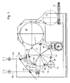
- Fig. 1 shows a schematic side view of a folder.
- This folder has two enemas 01; 02 for multilayer material webs 03; 04, in particular paper webs 03; 04, which in the following as inner or outer web 03; 04 are called.
- Both tracks 03; 04 each pass through a pair of draw rollers 06; 07 for adjusting their tension and meet a transport cylinder 11 in the amount of cutting gaps 08; 09 between the transport cylinder 11 on the one hand and one of the cutting cylinder 12; 13 on the other hand.
- the tracks contact 03; 04 preferably each first the transport cylinder 11 and then the cutting cylinder 12; 13, ie the tracks 03; 04 wrap around first the transport cylinder 11 and then the cutting cylinder 12; 13th
- Each cutting cylinder 12 and 13 has a circumference corresponding to at least one, preferably two lengths of the webs 03; 04 to be produced signatures and carries two cutting blades 14th
- the circumference of the transport cylinder 11 corresponds to more than five, in particular seven lengths of the signature. Seven at equal intervals in the peripheral surface of the transport cylinder 11 inserted counter cutting strips, z. B. hard rubber strips, serve as an abutment 15, each with the cutting of the webs 03; 04 cooperate with a cutting blade 14. Each of the abutment 15 is adjacent to a holding device 16, z. B. spur strip 16 with extendable puncture needles 23 (see Fig. 2 to 5 ) is arranged on the transport cylinder 11.
- the rotation of the two cutting cylinders 12; 13 is synchronized so that a cutting blade 14 of the cutting cylinder 13 always at the same time with a small gap between two successive, cut from the inner web 03 signatures and an abutment 15 passes through the cutting gap 09.
- Different techniques for creating this gap will be discussed below with reference to the Fig. 2 to 5 explained.
- the angular distance between the two cutting gaps 08; 09 is about 50 ° in the example shown here. This angular distance may differ from the angular distance of the spur strips 16 from each other (51.5 °) or a multiple thereof, so not at the two cutting gaps 08; 09 is cut simultaneously; even a half-integer multiple of this value is unfavorable from the viewpoint of vibration avoidance.
- each puncture strip 16 After passing through the cutting gap 09 each puncture strip 16 carries a total product, which is composed in each case of a cut off from the inner web 03 signature and a truncated from the outer web 04 signature. With each revolution of the transport cylinder 11 seven products are produced, as well as when both tracks 03; 04 in a conventional manner via a common inlet 01; 02 would be supplied. However, since the cutting of each signature on two cutting steps at the cutting gaps 08; 09 distributed, the force to be applied in each cutting step is lower, and a satisfactory synchronization of the machine is easier to maintain.
- FIG. 1 On the transport cylinder 11 are also seven in the FIG. 1 not shown folding blade attached, which are respectively extended upon reaching a gap 17 between the transport cylinder 11 and a jaw cylinder 18 to pass the transported on the transport cylinder 11 signatures on the jaw cylinder 18 in a conventional manner and to fold.
- the folded products are transferred from the jaw cylinder 18 to a paddle wheel 19 and are designed by the latter onto a conveyor belt 21.
- Fig. 2 shows a detailed view of the cutting gap 09 and its surroundings according to a first embodiment of the invention.
- Two of the seven puncture strips 16 of the transport cylinder 11 are in the Fig. 2 shown and with spur strips 16 '; Both are respectively pivotable about a shaft 22 and carry puncturing needles 23 which are oriented so that their protruding from the circumference of the transport cylinder 11 tip is further away from the center of the shaft 22 as their lying within the transport cylinder 11 base
- the puncturing needles 23 of the spur strip 16 ' are in a comparatively far extended position, in which they have previously also passed through the cutting gap 08. This same position is drawn in dashed lines at the location of the spur strip 16 ".
- the spur strip 16 is pivoted back into the interior of the transport cylinder 11. This pivoting movement causes a displacement of the point of intersection between the sprocket pins 23 and the surface of the transport cylinder 11 counter to the direction of rotation of the sprocket 16" Signature 24 compared to the position in which it was cut at the cutting gap 08 of the inner web 03, slightly shifted against the direction of rotation of the transport cylinder 11. After passing through the cutting gap 09, the spur strip 16 "returns to the position shown in dashed lines or even moves into an even further extended position so as to cancel out or overcompensate the backward shift of the signature 24.
- the signature is formed in each case 24 and immediately before truncated signature 27 a narrow gap 26, in which the cutting blade 14th engage and so the outer web 04 can press against the abutment 15 and cut, without running the risk, again one of the signatures 24; 27 to cut.
- Fig. 3 shows an alternative embodiment of the transport cylinder 11 and the cutting cylinder 13 in a partial section analogous to that of Fig. 2 ,
- the cutting cylinder 13 has for each cutting blade 14 on its outer circumference projecting bar 28 which passes through the cutting gap 09 in each case shortly before the associated cutting blade 14.
- a complementarily shaped groove 29 on the transport cylinder 11 is opposite the bar 28 at each nip passage, so that the bar 28 pushes a trailing edge portion of the 27 cut off from the inner web signature 27 and the outer web 04 in the groove 29.
- the spur strip 16 "pivots outwards again after its passage through the cutting gap 09 to generate the gap 26.
- a third embodiment is in Fig. 4 again shown with reference to a partial section of the transport cylinder 11 and the cutting cylinder 13.
- the cutting cylinder 13 is identical to that of Fig. 2
- the transport cylinder 11 differs by the arrangement of the shafts 22 about which the spurs 16 are pivotable. While in the embodiments of Fig. 2 and 3 These waves 22 are in the direction of rotation of the transport cylinder 11 in front of the point needles 23, they are in the embodiment of Fig. 4 arranged behind this.
- the orientation of the puncturing needles 23 with respect to the surface of the transport cylinder 11 is the same in all cases, they are slightly inclined against the surface normal in the direction of rotation of the transport cylinder 11 forward, so that acting on a spiked on the point needles 23 material tension this against the Surface of the transport cylinder 11 holds pressed.
- the outward movement of the puncturing needles 23 causes a shift of their intersection with the circumference of the transport cylinder 11 against the direction of movement and thus a departure of the leading edge of the held by the spur strip 16 ** signature 24 from the point of impact of the cutting blade 14 on the abutment 15th
- the puncturing needles 23 of the spur strip 16 *** are once again pulled back into the transport cylinder 11 in order to advance the signature 27 they hold in the circumferential direction and thus open the gap 26 at the level of the abutment 15
- a fourth embodiment of the cutting device is in Fig. 5 turn in a to Fig. 4 analog view shown.
- each of these segments 32 *, 32 **, ... is composed of a plurality of flexible blades, which are arranged in the axial direction of the transport cylinder 11 side by side and spaced by gaps. These columns are used in the transfer of the finished cut signatures 24; 27 at the jaw cylinder 18 respectively as outlet openings for prongs of a (not shown) folding blade.
- the ends of the fins are each in the circumferential direction of the Transport cylinder 11 sliding head strips 33 anchored.
- the segment 32 * is in a configuration in which the course of its lamellae corresponds to the cylindrical shape of the transport cylinder 11. After passage of such a segment 32 * through the cutting gap 09 whose head strips 33 are moved towards each other, so that its lamellae, as shown on the segment 32 ** form a project beyond the circumference of the transport cylinder 11 projection. As a result of this projection, the distance between the pin punctures 16 ** and 16 *** measured along the surface of the transport cylinder 11 is greater than that between the puncture strips 16 * and 16 **, the latter corresponds to the length of the signatures 24 generated at the cutting gap 08; 27. The bulge of the segment 32 ** therefore causes between the signatures 24 and 27, the gap 26 is formed, in which the cutting blade 14 of the cutting cylinder 13 can engage.
- the second cross-cutting device 11, 13 is disposed on the circumference of the transport cylinder 11 phase-shifted cutting.
- the section of the first cross-cutting device 11, 12 on the transport cylinder 11 takes place next to, in particular 10 mm next to, the other section of the second cross-cutting device 11, 13th
- the first and second cross-cutting devices 11, 13 are arranged in the circumferential direction on the transport cylinder 11.
- a further transport cylinder for transferring the signatures can be connected downstream in all modes of operation, which in turn can be followed by a jaw cylinder or a belt system.
- each of the tracks 03; 04 same patterns A and B in succession, ie in the transport direction.
- These patterns A and B are preferably printed with at least one forme cylinder of a printing unit which carries two identical patterns A or B on the circumference.
- the tracks 03; 04 are superimposed, so that signatures arise with superimposed patterns A and B, which pass in each case in the gap 17 to the subsequent Falklappenzylinder 18.
- the transport cylinder 11 does not necessarily have an odd-numbered division, but may also have an even division, preferably greater than 4 or 6.
- Patterns A, B, C, D preferably each designate two newspaper pages, A1, A2; B1, B2; C1, C2; D1, D2 each denote a newspaper page.
- Bahn 03 is at least one track 03; 04, but below is preferably one of several superimposed tracks 03; 04 existing strand to understand.
- the tracks 03; 04 are each printed with printing cylinders of printing units that either wear a pattern A or B on the circumference (single circumference) or two patterns A and B on the circumference (double circumference) wear.
- double-circumference form cylinder two similar patterns A, A and B, B or two different patterns A, B may be circumferentially arranged.
- the tracks carry 03; 04 in a first mode of operation one behind the other same pattern A or C and it will be on the transport cylinder 11 in a row at each Revolution same products formed and delivered directly to the subsequent jaw cylinder 18.
Abstract
Description
Die Erfindung betrifft eine Schneidvorrichtung zum Querschneiden wenigstens einer Materialbahn gemäß dem Oberbegriff des Anspruchs 1.The invention relates to a cutting device for cross-cutting at least one material web according to the preamble of claim 1.
Eine solche Schneidvorrichtung wird z. B. eingesetzt, um in einer Rollenrotationsdruckmaschine bedruckte Papierbahnen in einzelne Signaturen zu zerlegen.Such a cutting device is z. B. used to dissect in a web-fed rotary printing machine printed paper webs into individual signatures.
Bekannte Schneidvorrichtungen dieser Art umfassen einen Transportzylinder und einen Schneidzylinder, die gemeinsam drehbar sind und einen Spalt begrenzen, durch den ein Transportweg für die zu schneidende Materialbahn verläuft, und der Schneidzylinder trägt wenigstens ein Messer, das jeweils eine Signatur von der Materialbahn abschneidet, wenn es den Spalt durchläuft.Known cutting devices of this type comprise a transport cylinder and a cutting cylinder, which are rotatable together and define a gap through which a transport path for the material web to be cut passes, and the cutting cylinder carries at least one knife, which cuts off a signature from the material web, if it passes through the gap.
Die
Die
Die
Der Erfindung liegt die Aufgabe zugrunde, eine Schneidvorrichtung zum Querschneiden wenigstens einer Materialbahn zu schaffen.The invention is based on the object, a cutting device for transverse cutting to create at least one material web.
Die Aufgabe wird erfindungsgemäß durch die Merkmale des Anspruchs 1 gelöst.The object is achieved by the features of claim 1.
Die mit der Erfindung erzielbaren Vorteile bestehen insbesondere darin, dass sie das Zusammenfügen von zwei Materialbahnen, die auf den zwei Transportwegen dem Transportzylinder zugeführt werden, zu einem gemeinsamen Produkt ermöglicht bzw. die Verarbeitung einer Materialbahn mit einer sehr großen Zahl von Lagen durch Zusammenfügen aus zwei Teilbahnen erlaubt.The achievable with the present invention consist in particular in that it allows the joining of two webs of material, which are supplied to the transport cylinder on the two transport paths to a common product or the processing of a web with a very large number of layers by joining two Partial lanes allowed.
Die Verarbeitung von aus einer großen von Zahl von Lagen zusammengesetzten Materialbahnen mit herkömmlichen Schneidvorrichtungen bereitet aus mehreren Gründen Schwierigkeiten. Zum einen wirken Zugwalzen, die zum Einstellen einer erforderlichen Spannung der Materialbahn herkömmlicherweise vorgesehen werden, nur auf die jeweils äußersten Lagen der Materialbahn unmittelbar ein; auf die inneren Lagen wird ihre Kraft nur mittelbar durch Reibung der Materiallagen aneinander übertragen. Diese Reibungskräfte sind nicht exakt kontrollierbar, insbesondere dann nicht, wenn die Bahn um Kurven gelenkt werden muss, d. h. eine Walze umschlingt. Daher ist die Spannung der inneren Lagen einer solchen Bahn um so schlechter kontrollierbar, je größer die Zahl der Bahnen ist. Auch die zur Verarbeitung einer Bahn erforderlichen Kräfte, sei es beim Schneiden oder beim Einstechen von Punkturlöchern in die Bahn, sind um so größer, je größer die Zahl ihrer Lagen ist. Bei der Schneidvorrichtung sind diese Kräfte reduziert. Infolgedessen kann die Schneidvorrichtung ohne Qualitätseinbuße leichter und damit preiswerter als eine herkömmliche gebaut werden.The processing of material webs composed of a large number of layers with conventional cutting devices presents difficulties for several reasons. On the one hand, draw rolls, which are conventionally provided for setting a required tension of the material web, only act directly on the respectively outermost layers of the material web; on the inner layers their power is transferred only indirectly by friction of the material layers to each other. These frictional forces are not precisely controllable, especially not when the web needs to be steered around curves, i. H. a roll wraps around. Therefore, the larger the number of tracks, the less the tension of the inner layers of such a web is controllable. Also, the forces required to process a web, be it cutting or puncturing puncture holes in the web, are the greater, the greater the number of their layers. In the cutting device, these forces are reduced. As a result, the cutter can be made lighter and thus less expensive than a conventional one without sacrificing quality.
Um zu verhindern, dass beim Durchgang durch den zweiten Schneidspalt das zweite Schneidmesser erneut in die erste Bahn schneidet, ist die Drehung der zwei Schneidzylinder vorzugsweise so synchronisiert, dass das zweite Schneidmesser bei seinem Durchgang durch den zweiten Schneidspalt auf einen vom ersten Schneidmesser erzeugten Schnitt in der ersten Bahn trifft.In order to prevent the second cutting blade from again cutting into the first web when passing through the second cutting gap, the rotation of the two cutting cylinders is preferably synchronized so that the second cutting blade passes through the second cutting gap to one from the first cutting blade produced cut in the first lane meets.
Um das Treffen dieses Schnitts zu erleichtern, sind vorzugsweise Mittel vorgesehen, um die vom ersten Messer beim Schneiden der ersten Bahn an dieser erzeugten Schnittkanten auseinander zu rücken, so dass das zweite Messer bei seinem Durchgang durch den Spalt auf eine Lücke von nichtverschwindender Breite in der ersten Bahn stößt.In order to facilitate the making of this cut, means are preferably provided for pulling apart the cut edges produced by the first knife when cutting the first web, so that the second knife, as it passes through the nip, encounters a gap of non-disappearing width in the gap first track abuts.
Verschiedene bevorzugte Ausgestaltungen von Mitteln zum Auseinanderrücken der Schnittkanten sind in den Ausführungsbeispielen beschrieben.Various preferred embodiments of means for separating the cut edges are described in the embodiments.
Die Schneidvorrichtung ist vorzugsweise Teil eines Falzapparats, insbesondere kann der Transportzylinder gleichzeitig als Falzmesserzylinder des Falzapparats fungieren.The cutting device is preferably part of a folding apparatus, in particular, the transport cylinder can simultaneously act as a folding blade cylinder of the folder.
Ausführungsbeispiele der Erfindung sind in den Zeichnungen dargestellt und werden im folgenden näher beschrieben.Embodiments of the invention are illustrated in the drawings and will be described in more detail below.
Es zeigen:
- Fig. 1
- eine schematische Seitenansicht eines Falzapparats mit einer Schneidvorrichtung;
- Fig. 2 bis 5
- jeweils Teilschnitte des Transportzylinders und eines Schneidzylinders in unterschiedlichen Ausgestaltungen der Erfindung;
- Fig. 6
- eine Darstellung einer Betriebsweise;
- Fig. 7
- eine Darstellung einer anderen Betriebsweise.
- Fig. 1
- a schematic side view of a folding apparatus with a cutting device;
- Fig. 2 to 5
- each partial sections of the transport cylinder and a cutting cylinder in different embodiments of the invention;
- Fig. 6
- a representation of a mode of operation;
- Fig. 7
- a representation of another mode of operation.
Jeder Schneidzylinder 12 bzw. 13 hat einen Umfang entsprechend mindestens einer, vorzugsweise zweier Längen der aus den Bahnen 03; 04 herzustellenden Signaturen und trägt zwei Schneidmesser 14.Each
Der Umfang des Transportzylinders 11 entspricht mehr als fünf, insbesondere sieben Längen der Signatur. Sieben in gleichen Abständen in die Umfangsfläche des Transportzylinders 11 eingelassene Gegenschneidleisten, z. B. Hartgummistreifen, dienen als Widerlager 15, die jeweils beim Schneiden der Bahnen 03; 04 mit einem Schneidmesser 14 zusammenwirken. Jedem der Widerlager 15 benachbart ist jeweils eine Halteeinrichtung 16, z. B. Punkturleiste 16 mit ausfahrbaren Punkturnadeln 23 (siehe
In der in der
Die auf diese Weise von der inneren Bahn 03 abgeschnittene Signatur wird am Transportzylinder 11 weiter gefördert zum Schneidspalt 09, wo sich die äußere Bahn 04 darüber legt und ebenfalls von den Punkturnadeln 23 der Punkturleiste 16 aufgespießt wird.The cut off in this way from the
Die Drehung der zwei Schneidzylinder 12; 13 ist so synchronisiert, das ein Schneidmesser 14 des Schneidzylinders 13 immer gleichzeitig mit einer schmalen Lücke zwischen zwei aufeinander folgenden, aus der inneren Bahn 03 geschnittenen Signaturen und einem Widerlager 15 den Schneidspalt 09 durchläuft. Unterschiedliche Techniken zur Erzeugung dieser Lücke werden in folgenden noch anhand der
Der Winkelabstand zwischen den zwei Schneidspalten 08; 09 beträgt beim hier gezeigten Beispiel ca. 50°. Dieser Winkelabstand kann vom Winkelabstand der Punkturleisten 16 voneinander (51,5°) oder einem Vielfachen davon abweichen, damit nicht an den beiden Schneidspalten 08; 09 gleichzeitig geschnitten wird; auch ein halbzahliges Vielfaches dieses Werts ist unter dem Gesichtspunkt der Schwingungsvermeidung ungünstig.The angular distance between the two
Nach dem Durchgang durch den Schneidspalt 09 trägt jede Punkturleiste 16 ein Gesamtprodukt, das jeweils aus einem von der inneren Bahn 03 abgeschnittenen Signatur und einem von der äußeren Bahn 04 abgeschnittenen Signatur zusammengesetzt ist. Mit jeder Umdrehung des Transportzylinders 11 werden sieben Produkte erzeugt, genauso, wie wenn beide Bahnen 03; 04 in herkömmlicher Weise über einen gemeinsamen Einlauf 01; 02 zugeführt würden. Da sich allerdings das Abschneiden jeder einzelnen Signatur auf zwei Schneidschritte an den Schneidspalten 08; 09 verteilt, ist die in jedem Schneidschritt aufzubringende Kraft geringer, und ein befriedigender Gleichlauf der Maschine ist leichter aufrechtzuerhalten.After passing through the
Am Transportzylinder 11 sind ferner sieben in der
Im Vergleich hierzu ist die Punkturleiste 16" ein Stück weit ins Innere des Transportzylinders 11 zurückgeschwenkt. Diese Schwenkbewegung bewirkt eine Verschiebung des Schnittpunktes zwischen den Punkturnadeln 23 und der Oberfläche des Transportzylinders 11 entgegen dessen Drehrichtung. Durch diese Verschiebung ist die von der Punkturleiste 16" gehaltene Signatur 24 im Vergleich zu der Stellung, in der es am Schneidspalt 08 von der inneren Bahn 03 abgeschnitten wurde, geringfügig entgegen der Drehrichtung des Transportzylinders 11 verschoben. Nach dem Durchlauf durch den Schneidspalt 09 kehrt die Punkturleiste 16" in die gestrichelt gezeigte Stellung zurück oder geht gar in eine noch weiter ausgefahrene Stellung über, um so die Rückwärtsverschiebung der Signatur 24 wieder aufzuheben bzw. überzukompensieren. Auf diese Weise entsteht jeweils zwischen der Signatur 24 und einer unmittelbar zuvor abgeschnittenen Signatur 27 eine schmale Lücke 26, in die das Schneidmesser 14 eingreifen und so die äußere Bahn 04 gegen das Widerlager 15 pressen und durchtrennen kann, ohne Gefahr zu laufen, erneut auch eine der Signaturen 24; 27 zu schneiden.In comparison, the
Eine dritte Ausgestaltung ist in
Aus der veränderten Anordnung der Wellen 22 resultiert ein veränderter Ablauf der Schwenkbewegung der hier mit 16*; 16** bezeichneten Punkturleisten. Die Punkturleiste 16*, die noch weit vom Schneidspalt 09 entfernt ist, befindet sich in einer vergleichsweise wenig ausgefahrenen Position, in der ihre Punkturnadeln 23 weit genug über den Umfang des Transportzylinders 11 hinausreichen, um die innere Bahn 03 zu halten. Erst kurz vor Erreichen des Schneidspalts 09 wird die Punkturleiste 16* weiter ausgefahren, um auch die äußere Bahn 04 zu punktieren, wie an der Punkturleiste 16** zu erkenne. Bei dieser Ausgestaltung bewirkt die Auswärtsbewegung der Punkturnadeln 23 eine Verschiebung von deren Schnittpunkt mit dem Umfang des Transportzylinders 11 entgegen dessen Bewegungsrichtung und damit ein Abrücken des führenden Randes der von der Punkturleiste 16** gehaltenen Signatur 24 vom Auftreffpunkt des Schneidmessers 14 auf das Widerlager 15. Die Punkturnadeln 23 der Punkturleiste 16*** sind demgegenüber wieder ein Stück weiter in den Transportzylinder 11 zurückgezogen, um so die von ihnen gehaltene Signatur 27 in Umfangsrichtung vorzurücken und so die Lücke 26 in Höhe des Widerlagers 15 zu öffnenFrom the changed arrangement of the
Bei dieser Ausgestaltung werden mehrere Richtungswechsel in der Bewegung der Punkturnadeln 23 im Laufe einer Umdrehung des Transportzylinders 11 vermieden.In this embodiment, several changes of direction in the movement of the puncturing needles 23 are avoided in the course of a revolution of the
Eine vierte Ausgestaltung der Schneidvorrichtung ist in
Bei dieser Ausgestaltung sind am Umfang des Transportzylinders 11 jeweils zwischen zwei aufeinanderfolgenden Punkturleisten 16*, 16**, 16***,... Segmente 32*, 32**, ... zur Umfangsvergrößerung angeordnet. Jedes dieser Segmente 32*, 32**, ... setzt sich zusammen aus einer Mehrzahl von flexiblen Lamellen, die in axialer Richtung des Transportzylinders 11 nebeneinander angeordnet und durch Spalte beabstandet sind. Diese Spalte dienen bei der Übergabe der fertig geschnittenen Signaturen 24; 27 an den Falzklappenzylinder 18 jeweils als Austrittsöffnungen für Zinken eines (nicht dargestellten) Falzmessers. Die Enden der Lamellen sind jeweils an in Umfangsrichtung des Transportzylinders 11 verschiebbaren Kopfleisten 33 verankert.In this embodiment, on the circumference of the
Das Segment 32* befindet sich in einer Konfiguration, in der der Verlauf seiner Lamellen der Zylinderform des Transportzylinders 11 entspricht. Nach Durchgang eines solchen Segments 32* durch den Schneidspalt 09 werden dessen Kopfleisten 33 aufeinander zu verschoben, so das seine Lamellen, wie am Segment 32** gezeigt, einen über den Umfang des Transportzylinders 11 hinausgreifenden Vorsprung bilden. In Folge dieses Vorsprungs ist der entlang der Oberfläche des Transportzylinders 11 gemessene Abstand zwischen den Punkturleisten 16** und 16*** größer als der zwischen den Punkturleisten 16* und 16**, letzterer entspricht der Länge der am Schneidspalt 08 erzeugten Signaturen 24; 27. Die Ausbuchtung des Segments 32** bewirkt daher, dass zwischen den Signaturen 24 und 27 die Lücke 26 entsteht, in die das Schneidmesser 14 des Schneidzylinders 13 eingreifen kann.The
Die zweite Querschneideinrichtung 11, 13 ist auf den Umfang des Transportzylinder 11 phasenversetzt schneidend angeordnet.The second
Der Schnitt der ersten Querschneideinrichtung 11, 12 auf den Transportzylinder 11 erfolgt kurz neben, insbesondere 10 mm neben, dem andern Schnitt der zweiten Querschneideinrichtung 11, 13.The section of the first
Die erste und zweite Querschneideinrichtungen 11, 13 sind im Umfangsrichtung am Transportzylinder 11 angeordnet.The first and second
Anstelle des Falzklappenzylinders 18 kann in allen Betriebsweisen auch ein weiterer Transportzylinder zur Übernahme der Signaturen nachgeschalten sein, dem wiederum ein Falzklappenzylinder oder ein Bändersystem nachgeschaltet sein kann.Instead of the
Auch ist es möglich das jede der Bahnen 03; 04 gleiche Muster A bzw. B hintereinander, d. h. in Transportrichtung aufweist. Diese Muster A und B werden vorzugsweise mit mindestens einem Formzylinder einer Druckeinheit bedruckt, der am Umfang zwei gleiche Muster A oder B trägt. Die Bahnen 03; 04 werden übereinander geführt, so dass Signaturen mit übereinanderliegenden Muster A und B entstehen, die jeweils im Spalt 17 zu den nachfolgenden Falklappenzylinder 18 übergehen. Dazu muß der Transportzylinder 11 nicht zwingend eine ungeradzahlige Teilung aufweisen, sondern kann auch eine geradzahlige Teilung, vorzugsweise größer 4 oder 6 aufweisen.It is also possible that each of the
Die Muster A, B, C, D bezeichnen vorzugsweise jeweils zwei Zeitungsseiten, wobei A1, A2; B1, B2; C1, C2; D1, D2 jeweils eine Zeitungsseite bezeichnen.Patterns A, B, C, D preferably each designate two newspaper pages, A1, A2; B1, B2; C1, C2; D1, D2 each denote a newspaper page.
Unter der Bezeichnung Bahn 03; 04 ist mindestens eine Bahn 03; 04 zu verstehen, vorzugsweise ist darunter jedoch jeweils ein aus mehreren aufeinanderliegenden Bahnen 03; 04 bestehender Strang zu verstehen.Under the
Dabei können die Bahnen 03; 04 jeweils mit Formzylindern von Druckeinheiten bedruckt werden, die entweder ein Muster A bzw. B am Umfang tragen (Einfach-Umfang) oder zwei Muster A bzw. B am Umfang (Doppel-Umfang) tragen. Bei Doppel-Umfang-Formzylinder können zwei gleiche Muster A, A und B, B oder zwei verschiedene Muster A, B am Umfang angeordnet sein.The
Es sind daher vier Betriebsweisen möglich.There are therefore four modes of operation possible.
In einer ersten und zweiten Betriebsweise werden beide Bahnen 03; 04 vor dem ersten Einlauf 01; 02 auf dem Transportzylinder 11 zusammengeführt und mittels eines einzigen Schneidvorgangs getrennt.In a first and second mode of operation both
Dabei tragen die Bahnen 03; 04 in einer ersten Betriebsweise hintereinander gleiche Muster A bzw. C und es werden auf dem Transportzylinder 11 hintereinander bei jeder Umdrehung gleiche Produkte gebildet und direkt an den nachfolgenden Falzklappenzylinder 18 abgegeben.The tracks carry 03; 04 in a first mode of operation one behind the other same pattern A or C and it will be on the
In einer zweiten Betriebsweise tragen die Bahnen 03; 04 hintereinander alternierende Muster A, B bzw. C, D die bei einer ersten Umdrehung des mit einer ungeraden Anzahl von Feldern versehenen Transportzylinders 11 (= Sammelzylinder) alternierend auf den Transportzylinder 11 abgelegt werden und bei der zweiten Umdrehung zusätzlich mit einer zweiten Lage des falzenden Produktteiles versehen werden.In a second mode of operation, the
In einer dritten und vierten Betriebsweise werden zwei Bahnen 03; 04 getrennt zugeführt, wobei in der dritten Betriebsweise die Bahnen 03; 04 hintereinander alternierend Muster A, B bzw. C, D tragen.In a third and fourth mode of operation, two
Dabei werden bei einer ersten Umdrehung des Transportzylinders 11 (= Sammelzylinder) auf allen und jeder zweiten Punkturleiste 16 erst Signaturen mit Mustern A, C jeder Bahn 03; 04 geführt, so dass jetzt jede zweite Punkturleiste 16 eine Signatur mit Mustern A; C trägt und bei der zweiten Umdrehung werden dann nochmals von jeder Bahn 03; 04 zwei Signaturen mit Mustern B, D auf die Punkturleisten 16 geführt.In this case, in a first rotation of the transport cylinder 11 (= collecting cylinder) on all and every
Bei der zweiten Umdrehung der Transportzylinder 11 sind daher Signaturen von Mustern A, C, B, D auf den Punkturleisten 16 alternierend mit Punkturleisten 16, die lediglich Signaturen mit Mustern A, C tragen, wobei die Signaturen, d. h. das Produkt mit Mustern A, C, B, D jedes zweiten Feldes und den Falzklappenzylinder 18 übergeben werden.In the second rotation of the
In einer vierten Betriebsweise weisen die Bahnen 03; 04 hintereinander gleiche Muster A, A bzw. C, C auf, so dass bei jeder Umdrehung der Transportzylinder 11 jede Punkturleiste 16 Produkte mit Mustern A, C trägt, die bei Erreichen des Falzklappenzylinders 18 direkt an diesen übergeben werden.In a fourth mode of operation, the
- 0101
- Einlaufenema
- 0202
- Einlaufenema
- 0303
- Materialbahn, Papierbahn, erste Bahn, innere BahnMaterial web, paper web, first web, inner web
- 0404
- Materialbahn, Papierbahn, zweite Bahn, äußere BahnMaterial web, paper web, second web, outer web
- 0505
- --
- 0606
- Zugwalzenpaarpair of drawing rollers
- 0707
- Zugwalzenpaarpair of drawing rollers
- 0808
- Schneidspaltcutting gap
- 0909
- Schneidspaltcutting gap
- 1010
- --
- 1111
- Transportzylindertransport cylinder
- 1212
- Schneidzylindercutting cylinder
- 1313
- Schneidzylindercutting cylinder
- 1414
- Schneidmessercutting blade
- 1515
- Widerlagerabutment
- 1616
- Halteeinrichtung, PunkturleisteHolding device, spur strip
- 1717
- Spaltgap
- 1818
- Falzklappenzylinderjaw cylinder
- 1919
- Schaufelradpaddle wheel
- 2020
- --
- 2121
- Förderbandconveyor belt
- 2222
- Wellewave
- 2323
- PunkturnadelnPoint needles
- 2424
- Signatur, ProduktSignature, product
- 2525
- --
- 2626
- Lückegap
- 2727
- Signatur, ProduktSignature, product
- 2828
- Leistestrip
- 2929
- Rillegroove
- 3030
- --
- 3131
- --
- 3232
- Segmentsegment
- 3333
- Kopfleisteheader
- 16'16 '
- Halteeinrichtung, PunkturleisteHolding device, spur strip
- 16"16 "
- Halteeinrichtung, PunkturleisteHolding device, spur strip
- 16*16. *
- Halteeinrichtung, PunkturleisteHolding device, spur strip
- 16**16 **
- Halteeinrichtung, PunkturleisteHolding device, spur strip
- 16***16 ***
- Halteeinrichtung, PunkturleisteHolding device, spur strip
- 32*32 *
- Segmentsegment
- 32**32 **
- Segmentsegment
- AA
- Muster, Signatur mit Muster, Produkt mit MusterPattern, signature with pattern, product with pattern
- BB
- Muster, Signatur mit Muster, Produkt mit MusterPattern, signature with pattern, product with pattern
- CC
- Muster, Signatur mit Muster, Produkt mit MusterPattern, signature with pattern, product with pattern
- DD
- Muster, Signatur mit Muster, Produkt mit MusterPattern, signature with pattern, product with pattern
Claims (12)
- Cutting device for transverse cutting of at least one material web (03; 04) comprising a transport cylinder (11), the transport cylinder (11) being arranged so as to form a first cutting nip (08) with a first crosscutting device (11; 12), the transport cylinder (11) additionally being arranged so as to form a second cutting nip (09) with a second crosscutting device (11; 13), first crosscutting device (11; 12) and second crosscutting device (11; 13) being arranged offset in the circumferential direction of the transport cylinder (11), characterized in that the crosscutting devices (11, 12; 11, 13) have in each case a cutting cylinder (12; 13), in that the transport cylinder (11) and a first cutting cylinder (12) are rotatable together and bound a first cutting nip (08) through which a first transport path for a first material web (03) to be cut runs, the first cutting cylinder (12) carrying at least one cutting knife (14) for cutting off a first signature (24) from the first material web (03) during passage of the cutting knife (14) through the first cutting nip (08), in that a second transport path for a second material web (04) to be cut meets the first transport path on the transport cylinder (11), and in that a second cutting cylinder (13) is rotatable together with the transport cylinder (11) and together with this bounds a second cutting nip (09) through which both transport paths run, the second cutting cylinder (13) carrying at least one cutting knife (14) for cutting off a second signature (27) from the second material web (04) during passage of the cutting knife (14) through the second cutting nip (09), and in that the rotation of the two cutting cylinders (12; 13) is synchronized so that the second cutting knife (14), during its passage through the second cutting nip (09), meets a cut in the first material web (03), which cut is produced by the first cutting knife (14).
- Cutting device according to Claim 1, characterized in that the transport cylinder (11) has an abutment (15) for a cutting knife (14).
- Cutting device according to Claim 1, characterized in that the first crosscutting device (11, 12) is arranged so as to cut through a first material web (03) and the second crosscutting device (11, 13) is arranged so as to cut through a second material web (04).
- Cutting device according to Claim 1, characterized in that the second crosscutting device (11, 13) is arranged on the circumference of the transport cylinder (11) so as to cut with a phase offset.
- Cutting device according to Claim 4, characterized in that, on the transport cylinder (11), the cut of the first crosscutting device (11, 12) is effected close to, in particular less than 10 mm from, a cut of the second crosscutting device (11, 13).
- Cutting device according to Claim 1, characterized by means (16; 16'; 16"; 16*; 16**; 16***; 32*; 32**, 33) for drawing apart the cut edges produced by the first cutting knife (14) during cutting of the first material web (03) on said material web.
- Cutting device according to Claim 6, characterized in that the means (16; 16'; 16"; 16*; 16**; 16***; 32*; 32**, 33) for drawing apart the cut edges comprise a holding device (16"; 16**) for holding the first signature (24) cut off and for moving the first signature (24) in a direction opposite to the transport direction before the second cutting nip (09) is reached.
- Cutting device according to Claim 6 or 7, characterized in that the means (16; 16'; 16"; 16*; 16**; 16***; 32*; 32**, 33) for drawing apart the cut edges comprise a holding device (16"'; 16***) for holding the second signature (27) cut off and for moving the second signature (27) in the transport direction after passage through the second cutting nip (09).
- Cutting device according to Claims 7 or 8, characterized in that the holding device (16; 16'; 16"; 16*; 16**; 16***) is a pin strip (16; 16'; 16"; 16*; 16**; 16***).
- Cutting device according to any of Claims 6 to 9, characterized in that the means (16; 16'; 16"; 16*; 16**; 16***; 32*; 32**, 33) for drawing apart the cut edges comprise a groove (29) on the transport cylinder (11) and a strip (28) cooperating with the groove (29) and present on the second cutting cylinder (13).
- Cutting device according to Claim 1, characterized in that the circumference of the transport cylinder (11) is at least five signature lengths.
- Cutting device according to any of the preceding claims, characterized in that a lead-in (01; 02) is coordinated with each material web (03; 04).
Applications Claiming Priority (2)
| Application Number | Priority Date | Filing Date | Title |
|---|---|---|---|
| DE2002109190 DE10209190B4 (en) | 2002-03-04 | 2002-03-04 | Cutting device for cross cutting at least one material web |
| EP20030743293 EP1480903B1 (en) | 2002-03-04 | 2003-02-28 | Cutting device for the transverse cutting of at least one material web |
Related Parent Applications (2)
| Application Number | Title | Priority Date | Filing Date |
|---|---|---|---|
| EP03743293.7 Division | 2003-02-28 | ||
| EP20030743293 Division EP1480903B1 (en) | 2002-03-04 | 2003-02-28 | Cutting device for the transverse cutting of at least one material web |
Publications (2)
| Publication Number | Publication Date |
|---|---|
| EP2030935A1 EP2030935A1 (en) | 2009-03-04 |
| EP2030935B1 true EP2030935B1 (en) | 2010-03-10 |
Family
ID=27770928
Family Applications (2)
| Application Number | Title | Priority Date | Filing Date |
|---|---|---|---|
| EP20080171447 Expired - Lifetime EP2030935B1 (en) | 2002-03-04 | 2003-02-28 | Cutting device for the transverse cutting of at least one material web |
| EP20030743293 Expired - Lifetime EP1480903B1 (en) | 2002-03-04 | 2003-02-28 | Cutting device for the transverse cutting of at least one material web |
Family Applications After (1)
| Application Number | Title | Priority Date | Filing Date |
|---|---|---|---|
| EP20030743293 Expired - Lifetime EP1480903B1 (en) | 2002-03-04 | 2003-02-28 | Cutting device for the transverse cutting of at least one material web |
Country Status (9)
| Country | Link |
|---|---|
| US (1) | US7351189B2 (en) |
| EP (2) | EP2030935B1 (en) |
| JP (1) | JP4032029B2 (en) |
| CN (1) | CN1283535C (en) |
| AT (2) | ATE460376T1 (en) |
| AU (1) | AU2003227014A1 (en) |
| DE (3) | DE10209190B4 (en) |
| RU (1) | RU2283269C2 (en) |
| WO (1) | WO2003074402A1 (en) |
Families Citing this family (5)
| Publication number | Priority date | Publication date | Assignee | Title |
|---|---|---|---|---|
| DE102006042592B4 (en) * | 2006-09-11 | 2009-04-09 | Koenig & Bauer Aktiengesellschaft | folding |
| DE102007025797B4 (en) * | 2007-06-02 | 2009-02-26 | Koenig & Bauer Aktiengesellschaft | folding |
| DE102013017224A1 (en) * | 2013-10-17 | 2015-04-23 | Manroland Web Systems Gmbh | Method and device for processing a printing material web |
| EP3207803A1 (en) | 2016-02-17 | 2017-08-23 | Haas Food Equipment GmbH | Method of and device for cutting dough output by an extrusion machine |
| DE102018108982A1 (en) * | 2018-04-16 | 2019-10-17 | Manroland Goss Web Systems Gmbh | Clamping lever for attaching machining tools to a rotatably mounted element of a printing press |
Family Cites Families (18)
| Publication number | Priority date | Publication date | Assignee | Title |
|---|---|---|---|---|
| DE239837C (en) | ||||
| US2891791A (en) * | 1955-12-19 | 1959-06-23 | Miehle Goss Dexter Inc | Jaw folding mechanism |
| DE2846191C3 (en) * | 1978-10-24 | 1981-08-13 | Koenig & Bauer AG, 8700 Würzburg | Folder for web-fed rotary printing machines |
| DE3139117C1 (en) * | 1981-10-01 | 1983-04-21 | M.A.N.- Roland Druckmaschinen AG, 6050 Offenbach | Variable folder with a pair of cutting cylinders and a pair of tear-off rollers arranged below this |
| DE3151283C1 (en) * | 1981-12-24 | 1983-04-21 | M.A.N.- Roland Druckmaschinen AG, 6050 Offenbach | Folder |
| US4754959A (en) | 1985-08-02 | 1988-07-05 | M.A.N. Roland Druckmaschinen Aktiengesellschaft | Folding apparatus for transverse folding and transporting of two types of printed substrates |
| DE3527710A1 (en) * | 1985-08-02 | 1987-02-12 | Roland Man Druckmasch | FOLDING APPARATUS FOR CROSS FOLDING PRINTED COPIES |
| DE3637110C1 (en) * | 1986-10-31 | 1988-05-19 | Heidelberger Druckmasch Ag | Device for cutting and dividing a continuous flow of printed products |
| US5024128A (en) * | 1989-02-21 | 1991-06-18 | Campbell Jr Gaines P | Sheeter for web fed printing press |
| DE4316134C2 (en) * | 1993-05-13 | 1997-03-13 | Heidelberger Druckmasch Ag | Process for the transverse folding of webs and folder for carrying out the process |
| DE9320814U1 (en) | 1993-12-24 | 1995-02-09 | Koenig & Bauer Ag | Device for producing folded products |
| DE4344362C2 (en) | 1993-12-24 | 1998-02-26 | Koenig & Bauer Albert Ag | Device for producing folded products |
| JPH10194588A (en) | 1997-01-07 | 1998-07-28 | Toshiba Mach Co Ltd | Two-way folder for printer |
| US7338425B1 (en) * | 2000-01-12 | 2008-03-04 | Goss International Americas, Inc. | Variable length cutting device |
| DE10116346B4 (en) * | 2001-04-02 | 2006-03-02 | Koenig & Bauer Ag | folding |
| US6733431B2 (en) * | 2001-09-19 | 2004-05-11 | Heidelberger Druckmaschinen Ag | Device and method for folding newspapers with flexible inserting position |
| DE10209214B4 (en) * | 2002-03-04 | 2004-03-25 | Koenig & Bauer Ag | cutter |
| DE20321547U1 (en) * | 2003-06-12 | 2007-11-29 | Man Roland Druckmaschinen Ag | Cutting cylinder for cross-cutting a substrate web in a rotary printing machine |
-
2002
- 2002-03-04 DE DE2002109190 patent/DE10209190B4/en not_active Expired - Fee Related
-
2003
- 2003-02-28 RU RU2004120788A patent/RU2283269C2/en not_active IP Right Cessation
- 2003-02-28 EP EP20080171447 patent/EP2030935B1/en not_active Expired - Lifetime
- 2003-02-28 AT AT08171447T patent/ATE460376T1/en active
- 2003-02-28 DE DE50312521T patent/DE50312521D1/en not_active Expired - Lifetime
- 2003-02-28 WO PCT/DE2003/000673 patent/WO2003074402A1/en active Application Filing
- 2003-02-28 AT AT03743293T patent/ATE461148T1/en active
- 2003-02-28 JP JP2003572882A patent/JP4032029B2/en not_active Expired - Fee Related
- 2003-02-28 CN CNB038040824A patent/CN1283535C/en not_active Expired - Fee Related
- 2003-02-28 DE DE50312508T patent/DE50312508D1/en not_active Expired - Lifetime
- 2003-02-28 EP EP20030743293 patent/EP1480903B1/en not_active Expired - Lifetime
- 2003-02-28 US US10/505,872 patent/US7351189B2/en not_active Expired - Fee Related
- 2003-02-28 AU AU2003227014A patent/AU2003227014A1/en not_active Abandoned
Also Published As
| Publication number | Publication date |
|---|---|
| EP1480903A1 (en) | 2004-12-01 |
| CN1283535C (en) | 2006-11-08 |
| WO2003074402B1 (en) | 2004-03-04 |
| JP4032029B2 (en) | 2008-01-16 |
| US20050160889A1 (en) | 2005-07-28 |
| JP2005519007A (en) | 2005-06-30 |
| WO2003074402A1 (en) | 2003-09-12 |
| DE10209190B4 (en) | 2004-03-04 |
| US7351189B2 (en) | 2008-04-01 |
| RU2004120788A (en) | 2005-05-27 |
| AU2003227014A1 (en) | 2003-09-16 |
| EP1480903B1 (en) | 2010-03-17 |
| CN1633387A (en) | 2005-06-29 |
| DE10209190A1 (en) | 2003-09-25 |
| EP2030935A1 (en) | 2009-03-04 |
| ATE461148T1 (en) | 2010-04-15 |
| DE50312521D1 (en) | 2010-04-29 |
| ATE460376T1 (en) | 2010-03-15 |
| DE50312508D1 (en) | 2010-04-22 |
| RU2283269C2 (en) | 2006-09-10 |
Similar Documents
| Publication | Publication Date | Title |
|---|---|---|
| EP0859733B1 (en) | Process and device for producing multi-layered newspaper products with a tabloid section | |
| DE3527712A1 (en) | FOLDING APPARATUS WITH A COLLECTING DEVICE BEFORE THE THIRD FOLD | |
| EP2039640B1 (en) | Device and method for producing a printed product and printed product | |
| DE60111037T2 (en) | COMBINATION OF A ROTATION FOLDING MACHINE WITH A FOLDING CYLINDER FOR A PRINTING MACHINE | |
| EP1922276B1 (en) | Folding device | |
| EP1802466A2 (en) | Method and printing machine for producing a printed product with a number of volumes | |
| EP2030935B1 (en) | Cutting device for the transverse cutting of at least one material web | |
| DE10238736A1 (en) | Method and device for folding a printed product | |
| EP1483189B1 (en) | Cutting device | |
| EP1480902B1 (en) | Transport device | |
| DE19927920A1 (en) | Cutting device for folding apparatus of rotary printing press, in which one cylinder carries perforating cutter and other carries perforating counter-cutter | |
| DE102006057453B4 (en) | folding | |
| EP1620343B1 (en) | Rotary folder comprising a cutting device for cross-cutting at least one web | |
| DE4140365C2 (en) | Device for trimming a web of material | |
| DE102004005807B4 (en) | folding | |
| DE102016216429B4 (en) | Printed product, method and web-fed printing machine for producing a printed product | |
| DE102014207835B4 (en) | Method and printing machine for the production of printed products | |
| DE102014222387B4 (en) | Process for the production of a printed product as well as a printed product | |
| EP4282657A1 (en) | Folding apparatus of an offset web-fed printing press and offset web-fed printing press | |
| DE102012203102B4 (en) | Web printing machine and method for operating a web printing machine | |
| EP3398891A1 (en) | Device for producing collections of sheet-shaped printed products, and folding apparatus for folding collections of sheet-shaped printed products | |
| DE102011102542A1 (en) | Folding unit for web-fed rotary printing machine e.g. newspaper printing machine, has support cylinders that are located in common strand running space with respect to cutting cylinders for processing web strand | |
| DE10052475A1 (en) | Device and method for guiding a web after a cutting device |
Legal Events
| Date | Code | Title | Description |
|---|---|---|---|
| PUAI | Public reference made under article 153(3) epc to a published international application that has entered the european phase |
Free format text: ORIGINAL CODE: 0009012 |
|
| AC | Divisional application: reference to earlier application |
Ref document number: 1480903 Country of ref document: EP Kind code of ref document: P |
|
| AK | Designated contracting states |
Kind code of ref document: A1 Designated state(s): AT BE BG CH CY CZ DE DK EE ES FI FR GB GR HU IE IT LI LU MC NL PT SE SI SK TR |
|
| 17P | Request for examination filed |
Effective date: 20090218 |
|
| GRAP | Despatch of communication of intention to grant a patent |
Free format text: ORIGINAL CODE: EPIDOSNIGR1 |
|
| AKX | Designation fees paid |
Designated state(s): AT BE BG CH CY CZ DE DK EE ES FI FR GB GR HU IE IT LI LU MC NL PT SE SI SK TR |
|
| GRAS | Grant fee paid |
Free format text: ORIGINAL CODE: EPIDOSNIGR3 |
|
| GRAA | (expected) grant |
Free format text: ORIGINAL CODE: 0009210 |
|
| AC | Divisional application: reference to earlier application |
Ref document number: 1480903 Country of ref document: EP Kind code of ref document: P |
|
| AK | Designated contracting states |
Kind code of ref document: B1 Designated state(s): AT BE BG CH CY CZ DE DK EE ES FI FR GB GR HU IE IT LI LU MC NL PT SE SI SK TR |
|
| REG | Reference to a national code |
Ref country code: GB Ref legal event code: FG4D Free format text: NOT ENGLISH |
|
| REG | Reference to a national code |
Ref country code: CH Ref legal event code: EP |
|
| REG | Reference to a national code |
Ref country code: IE Ref legal event code: FG4D |
|
| REF | Corresponds to: |
Ref document number: 50312508 Country of ref document: DE Date of ref document: 20100422 Kind code of ref document: P |
|
| REG | Reference to a national code |
Ref country code: NL Ref legal event code: VDEP Effective date: 20100310 |
|
| PG25 | Lapsed in a contracting state [announced via postgrant information from national office to epo] |
Ref country code: SI Free format text: LAPSE BECAUSE OF FAILURE TO SUBMIT A TRANSLATION OF THE DESCRIPTION OR TO PAY THE FEE WITHIN THE PRESCRIBED TIME-LIMIT Effective date: 20100310 Ref country code: FI Free format text: LAPSE BECAUSE OF FAILURE TO SUBMIT A TRANSLATION OF THE DESCRIPTION OR TO PAY THE FEE WITHIN THE PRESCRIBED TIME-LIMIT Effective date: 20100310 |
|
| REG | Reference to a national code |
Ref country code: IE Ref legal event code: FD4D |
|
| PG25 | Lapsed in a contracting state [announced via postgrant information from national office to epo] |
Ref country code: SE Free format text: LAPSE BECAUSE OF FAILURE TO SUBMIT A TRANSLATION OF THE DESCRIPTION OR TO PAY THE FEE WITHIN THE PRESCRIBED TIME-LIMIT Effective date: 20100310 Ref country code: EE Free format text: LAPSE BECAUSE OF FAILURE TO SUBMIT A TRANSLATION OF THE DESCRIPTION OR TO PAY THE FEE WITHIN THE PRESCRIBED TIME-LIMIT Effective date: 20100310 Ref country code: NL Free format text: LAPSE BECAUSE OF FAILURE TO SUBMIT A TRANSLATION OF THE DESCRIPTION OR TO PAY THE FEE WITHIN THE PRESCRIBED TIME-LIMIT Effective date: 20100310 Ref country code: CY Free format text: LAPSE BECAUSE OF FAILURE TO SUBMIT A TRANSLATION OF THE DESCRIPTION OR TO PAY THE FEE WITHIN THE PRESCRIBED TIME-LIMIT Effective date: 20100310 Ref country code: GR Free format text: LAPSE BECAUSE OF FAILURE TO SUBMIT A TRANSLATION OF THE DESCRIPTION OR TO PAY THE FEE WITHIN THE PRESCRIBED TIME-LIMIT Effective date: 20100611 Ref country code: ES Free format text: LAPSE BECAUSE OF FAILURE TO SUBMIT A TRANSLATION OF THE DESCRIPTION OR TO PAY THE FEE WITHIN THE PRESCRIBED TIME-LIMIT Effective date: 20100621 |
|
| PG25 | Lapsed in a contracting state [announced via postgrant information from national office to epo] |
Ref country code: CZ Free format text: LAPSE BECAUSE OF FAILURE TO SUBMIT A TRANSLATION OF THE DESCRIPTION OR TO PAY THE FEE WITHIN THE PRESCRIBED TIME-LIMIT Effective date: 20100310 Ref country code: BG Free format text: LAPSE BECAUSE OF FAILURE TO SUBMIT A TRANSLATION OF THE DESCRIPTION OR TO PAY THE FEE WITHIN THE PRESCRIBED TIME-LIMIT Effective date: 20100610 Ref country code: SK Free format text: LAPSE BECAUSE OF FAILURE TO SUBMIT A TRANSLATION OF THE DESCRIPTION OR TO PAY THE FEE WITHIN THE PRESCRIBED TIME-LIMIT Effective date: 20100310 |
|
| PLBE | No opposition filed within time limit |
Free format text: ORIGINAL CODE: 0009261 |
|
| STAA | Information on the status of an ep patent application or granted ep patent |
Free format text: STATUS: NO OPPOSITION FILED WITHIN TIME LIMIT |
|
| PG25 | Lapsed in a contracting state [announced via postgrant information from national office to epo] |
Ref country code: IE Free format text: LAPSE BECAUSE OF FAILURE TO SUBMIT A TRANSLATION OF THE DESCRIPTION OR TO PAY THE FEE WITHIN THE PRESCRIBED TIME-LIMIT Effective date: 20100310 Ref country code: PT Free format text: LAPSE BECAUSE OF FAILURE TO SUBMIT A TRANSLATION OF THE DESCRIPTION OR TO PAY THE FEE WITHIN THE PRESCRIBED TIME-LIMIT Effective date: 20100712 Ref country code: DK Free format text: LAPSE BECAUSE OF FAILURE TO SUBMIT A TRANSLATION OF THE DESCRIPTION OR TO PAY THE FEE WITHIN THE PRESCRIBED TIME-LIMIT Effective date: 20100310 |
|
| 26N | No opposition filed |
Effective date: 20101213 |
|
| PG25 | Lapsed in a contracting state [announced via postgrant information from national office to epo] |
Ref country code: IT Free format text: LAPSE BECAUSE OF FAILURE TO SUBMIT A TRANSLATION OF THE DESCRIPTION OR TO PAY THE FEE WITHIN THE PRESCRIBED TIME-LIMIT Effective date: 20100310 |
|
| PGFP | Annual fee paid to national office [announced via postgrant information from national office to epo] |
Ref country code: CH Payment date: 20110225 Year of fee payment: 9 |
|
| BERE | Be: lapsed |
Owner name: KOENIG & BAUER A.G. Effective date: 20110228 |
|
| PG25 | Lapsed in a contracting state [announced via postgrant information from national office to epo] |
Ref country code: MC Free format text: LAPSE BECAUSE OF NON-PAYMENT OF DUE FEES Effective date: 20110228 |
|
| PG25 | Lapsed in a contracting state [announced via postgrant information from national office to epo] |
Ref country code: BE Free format text: LAPSE BECAUSE OF NON-PAYMENT OF DUE FEES Effective date: 20110228 |
|
| PGFP | Annual fee paid to national office [announced via postgrant information from national office to epo] |
Ref country code: FR Payment date: 20120229 Year of fee payment: 10 |
|
| PGFP | Annual fee paid to national office [announced via postgrant information from national office to epo] |
Ref country code: DE Payment date: 20120315 Year of fee payment: 10 |
|
| PGFP | Annual fee paid to national office [announced via postgrant information from national office to epo] |
Ref country code: GB Payment date: 20120221 Year of fee payment: 10 |
|
| REG | Reference to a national code |
Ref country code: CH Ref legal event code: PL |
|
| PG25 | Lapsed in a contracting state [announced via postgrant information from national office to epo] |
Ref country code: LI Free format text: LAPSE BECAUSE OF NON-PAYMENT OF DUE FEES Effective date: 20120229 Ref country code: CH Free format text: LAPSE BECAUSE OF NON-PAYMENT OF DUE FEES Effective date: 20120229 |
|
| REG | Reference to a national code |
Ref country code: AT Ref legal event code: MM01 Ref document number: 460376 Country of ref document: AT Kind code of ref document: T Effective date: 20110228 |
|
| PG25 | Lapsed in a contracting state [announced via postgrant information from national office to epo] |
Ref country code: AT Free format text: LAPSE BECAUSE OF NON-PAYMENT OF DUE FEES Effective date: 20110228 |
|
| PG25 | Lapsed in a contracting state [announced via postgrant information from national office to epo] |
Ref country code: LU Free format text: LAPSE BECAUSE OF NON-PAYMENT OF DUE FEES Effective date: 20110228 |
|
| PG25 | Lapsed in a contracting state [announced via postgrant information from national office to epo] |
Ref country code: TR Free format text: LAPSE BECAUSE OF FAILURE TO SUBMIT A TRANSLATION OF THE DESCRIPTION OR TO PAY THE FEE WITHIN THE PRESCRIBED TIME-LIMIT Effective date: 20100310 |
|
| GBPC | Gb: european patent ceased through non-payment of renewal fee |
Effective date: 20130228 |
|
| PG25 | Lapsed in a contracting state [announced via postgrant information from national office to epo] |
Ref country code: HU Free format text: LAPSE BECAUSE OF FAILURE TO SUBMIT A TRANSLATION OF THE DESCRIPTION OR TO PAY THE FEE WITHIN THE PRESCRIBED TIME-LIMIT Effective date: 20100310 |
|
| REG | Reference to a national code |
Ref country code: FR Ref legal event code: ST Effective date: 20131031 |
|
| REG | Reference to a national code |
Ref country code: DE Ref legal event code: R119 Ref document number: 50312508 Country of ref document: DE Effective date: 20130903 |
|
| PG25 | Lapsed in a contracting state [announced via postgrant information from national office to epo] |
Ref country code: DE Free format text: LAPSE BECAUSE OF NON-PAYMENT OF DUE FEES Effective date: 20130903 Ref country code: GB Free format text: LAPSE BECAUSE OF NON-PAYMENT OF DUE FEES Effective date: 20130228 Ref country code: FR Free format text: LAPSE BECAUSE OF NON-PAYMENT OF DUE FEES Effective date: 20130228 |