EP2030882B1 - A cowling assembly for a motorcycle and a motorcycle equiped with such a cowling assembly - Google Patents
A cowling assembly for a motorcycle and a motorcycle equiped with such a cowling assembly Download PDFInfo
- Publication number
- EP2030882B1 EP2030882B1 EP07017225A EP07017225A EP2030882B1 EP 2030882 B1 EP2030882 B1 EP 2030882B1 EP 07017225 A EP07017225 A EP 07017225A EP 07017225 A EP07017225 A EP 07017225A EP 2030882 B1 EP2030882 B1 EP 2030882B1
- Authority
- EP
- European Patent Office
- Prior art keywords
- support element
- assembly
- motorcycle
- extending
- receive
- Prior art date
- Legal status (The legal status is an assumption and is not a legal conclusion. Google has not performed a legal analysis and makes no representation as to the accuracy of the status listed.)
- Active
Links
Images




Classifications
-
- B—PERFORMING OPERATIONS; TRANSPORTING
- B62—LAND VEHICLES FOR TRAVELLING OTHERWISE THAN ON RAILS
- B62J—CYCLE SADDLES OR SEATS; AUXILIARY DEVICES OR ACCESSORIES SPECIALLY ADAPTED TO CYCLES AND NOT OTHERWISE PROVIDED FOR, e.g. ARTICLE CARRIERS OR CYCLE PROTECTORS
- B62J17/00—Weather guards for riders; Fairings or stream-lining parts not otherwise provided for
- B62J17/02—Weather guards for riders; Fairings or stream-lining parts not otherwise provided for shielding only the rider's front
-
- B—PERFORMING OPERATIONS; TRANSPORTING
- B62—LAND VEHICLES FOR TRAVELLING OTHERWISE THAN ON RAILS
- B62K—CYCLES; CYCLE FRAMES; CYCLE STEERING DEVICES; RIDER-OPERATED TERMINAL CONTROLS SPECIALLY ADAPTED FOR CYCLES; CYCLE AXLE SUSPENSIONS; CYCLE SIDECARS, FORECARS, OR THE LIKE
- B62K19/00—Cycle frames
- B62K19/30—Frame parts shaped to receive other cycle parts or accessories
Definitions
- the present invention relates to the field of motor cycles.
- the present invention relates to a front cowling assembly for a motor cycle and a respective motor cycle equipped with such a cowling assembly.
- the present invention relates to the way such a cowling assembly is mounted to and removed from a motor cycle.
- those accessories and/or equipments usually belonging to the front cowling element of a motor cycle may be cited; these accessories and/or component parts in turn may comprise a front cowling cover, rear mirrors, front headlights and/or direction indicators, the speedometer, the fuel level indicator, the oil pressure indicator, the cooling fluid level indicator and similar equipments.
- these accessories and/or component parts in turn may comprise a front cowling cover, rear mirrors, front headlights and/or direction indicators, the speedometer, the fuel level indicator, the oil pressure indicator, the cooling fluid level indicator and similar equipments.
- Still another disadvantage affecting the prior art solutions relates to the fact that the operator, for the purpose of removing component parts or accessories or even equipments from the cowling assembly is requested to stay beside the motor cycle; the same then furthermore applies when the component parts, accessories, or equipments have to be mounted again to the cowling assembly.
- cowling assemblies for motorcycles can be found in each of documents DE 103 42 106 A1 and DE 10 2004 057 132 A1
- an object of the present invention to provide a solution allowing to overcome the problems as stated above.
- the present invention is based on the consideration that the problems affecting the prior art solutions, in particular, the prior art cowling assemblies may be overcome if the cowling assembly, as a whole, can be mounted to and removed from the motor cycle.
- the overall cowling assembly may be assembled and/or finished first, and then subsequently mounted as a whole to the motor cycle.
- the possibility is offered to the operator to mount each of the accessories belonging to the cowling assembly singularly and in convenient conditions to the cowling assembly, so that this cowling assembly, along with the accessories mounted thereto, can be subsequently mounted to the motor cycle as a single piece or part.
- said cowling assembly may be first removed from the motor cycle as a whole, thus allowing the operator to work on one or more of the accessories or equipments of the motor cycle in easy and convenient conditions.
- Still a further consideration on which the present invention is made relates to the fact that the problems affecting the prior art solutions, in particular, the prior art cowling assemblies, can be overcome or at least, drastically reduced or minimized by providing a cowling assembly comprising a support element with fixing means adapted to allow said support element and the overall cowling assembly to be quickly mounted to and removed from the motor cycle.
- Another consideration on which the present invention is made relates to the fact that the operation for mounting and/or removing the cowling assembly may be further accelerated or speeded-up if the fixing means of the support element are located in a position easily accessible by an operator.
- the present invention is understood to be of particular advantage when applied to two-wheeled motor cycles, such as, for instance, motor bikes. For this reason, examples will be given in the following, in which corresponding embodiments of the front cowling assembly according to the present invention are applied to motor bikes. However, it has to be appreciated that the applications of the front cowling assembly according to the present invention are not limited to the case of motor bikes. On the contrary, the front cowling assembly according to the present invention may also be applied to other motor cycles and/or motor vehicles, in particular, to three or even four-wheeled motor cycles such as for instance, choppers, quads or the like.
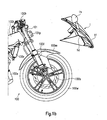
- FIG. 1a the front portion of a motor cycle 100 is depicted.
- Fig. 1a essentially the front portion of a motor cycle has been depicted whilst some portions or component parts or even accessories or equipments common to usual motor cycles have been omitted in Fig. 1 for the sake of clarity, the essential features of common motor cycles may be recognized when looking at Fig. 1a .
- These features relate in particular, to a front wheel 100w, with said front wheel 100w comprising a brake disk 100b and being supported by a front fork 100f; said front fork 100f supports moreover a front fender 100m provided to avoid the driver and/or passenger or even the motor cycle 100 from being splashed with mud or water lying on the bottom or the like.
- Side covering elements 100c are mounted to the motor cycle 100 on opposite sides thereof; components of the motor cycle 100 such as, for instance, the engine, the crankcase, the cylinder or the like have therefore to be understood as being located in the area defined by said side covering elements 100c, in combination, and therefore, as being located behind the right-side cover element 100c depicted in Fig. 1 .
- the motor cycle 100 further comprises a fuel tank 100t (partially covered by the side covering element 100c), along with a handlebar 100h provided with brake handles and corresponding cables extending therefrom.
- a front cowling assembly 1 is mounted to the motor cycle 100, with said front cowling assembly 1, supporting and/or comprising as depicted in Fig.
- the motor cycle 100 comprises, in the area defined by said side covering elements 100c, a radiator 100r and an exhaust gas purifying pipe 100e.
- the front fork 100f supporting the front wheel 100w and the front fender 100m extends from a steering tube 101 which is in turn fixed and/or connected to the main frame (not depicted in the drawings) of the motor cycle 100. It appears moreover from Fig.
- a fixing element 101p extends from the steering tube 101; as it will be better appreciated by means of the following disclosure, said fixing element 101p belongs to fixing means adapted to allow the front cowling assembly 1 to be mounted to the motor cycle 100 as depicted in Fig. 1a .
- the same considerations also apply to the front cowling assembly 1 depicted in Figs. 1a and 1b ; in fact, even if essentially only the rear mirrors 1h, the headlights 1f and the front direction indicators 1b have been explicitly identified in Fig. 1b as belonging or being supported by the front cowling assembly 1, it has to be appreciated that said front cowling assembly 1 is adapted to support other equipments in addition to those clearly depicted and identified in Fig. 1b .
- This additional equipments may comprise, for instance, a speedometer, a fuel level indicator, an oil pressure indicator, a cooling fluid level indicator and/or even further equipments usually needed by the driver to check and/or manage the functioning of the motor cycle 100.
- the front cowling assembly 1 Whilst further details and/or features of the front cowling assembly 1 according to the present invention will be comprehensively described in the following, it can be appreciated at present, when looking at Figs. 1a and 1b , in combination, that the basic idea of the present invention relates to the fact that the front cowling assembly 1 depicted therein may be mounted to and removed from the motor cycle 100 as a whole. That means, that for instance removing the front cowling assembly 1 from the motor cycle 100, results in all those accessories or equipments supported by said front cowling assembly 1 being also removed from the motor cycle 100 with a unique operation. The same applies when the front cowling assembly 1 has to be mounted to the motor cycle 100; mounting said front cowling assembly 1 to the motor cycle as depicted in Fig.
- said accessories and/or equipments supported by or belonging to the front cowling assembly 1 may comprise the rear mirrors 1h, the headlights 1f and the front direction indicators 1d identified in Fig. 1b , along with other accessories and/or equipments, such as a speedometer and/or similar control equipments.
- the operator when for instance, the need arises to repair or even substitute one of said equipment, let's say the fuel level indicator, the operator is not requested to stay beside the motor cycle and to work in difficult conditions; on the contrary, the possibility is given to the operator, to entirely remove the front cowling assembly 1 from the motor cycle, to put it for instance on a working table so as to be allowed to repair or substitute said fuel level indicator in convenient conditions, for instance, even sitting. Accordingly, the operator may turn or move the front cowling assembly 1 so as to dispose it in the most convenient position offering easy access to said fuel level indicator.
- the operations may therefore be accelerated and/or speeded up, with evident corresponding advantages in terms of reduced and/or contained costs.
- FIG. 2a and 2b some additional features and/or details of the front cowling assembly according to the present invention will be disclosed; in Figs. 2a and 2b , those features which have already been described with reference to Figs. 1a and 1b are identified by the same reference numerals.
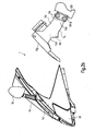
- the front cowling assembly 1 comprises a support element 1s and a front cowling cover 1c; moreover, as apparent from Fig. 2a , said front cowling cover is adapted to be supported by said support element 1s.
- fixing means may be provided, such as, for instance, clips, screws, bolts or the like.
- the rear mirrors 1h, the headlights 1f and the front direction indicators 1d are mounted directly to the front cowling cover 1c.
- said accessories are mounted to the support element 1s.
- the front cowling cover 1c will comprise corresponding apertures adapted to receive said accessories.
- the support element 1s (the shape and layout of which will be more comprehensively described in the following) comprises a front end portion or surface 1fp adapted to match with the front cowling cover 1c, along with a rear end portion 1sr.
- the support element 1s comprises a top or upper surface 1u, from which two opposite side walls 1ll and 1lr (see also, Fig. 4b ) extends downward so as to define a recess or cavity 1ca below said upper or top surface 1u.
- fixing means 1a are provided, with said fixing means 1a allowing the support element 1s to be connected or fixed through its rear end portion 1sr to the main frame of the motor cycle, in particular, to the plate 101p extending from the steering tube 1001.
- the front cowling assembly 1 may be mounted and removed as a whole, to and from the motor cycle 100, respectively by simply detaching from and fixing to, respectively the support element 1s of said front cowling assembly 1; these may, in particular, be obtained by acting on the fixing means 1a which co-operate with the protruding plate 101p extending from the steering tube 101.
- a simple, unique operation is therefore requested for removing from and/or mounting to the motor cycle 100, all the equipments supported by or belonging to the front cowling assembly 1, simultaneously.
- the position at which the fixing means 1a are located allows easy access to said fixing means 1a, so that mounting and/removing the whole front cowling assembly 1 results in being strongly simplified, thus resulting in the corresponding operations being accelerated and the resulting costs being reduced.
- the support element 1s comprises, in its rear end portion 1sr, a slot 1sl adapted to receive the protruding plate 101p.
- the support element 1s During mounting of the front cowling assembly 1 to the motor cycle, it is therefore requested first to act on the support element 1s so as to allow the protruding plate 101p to enter into the slot 100sl so as to be received inside said slot 100sl.
- said fixing means 1a are introduced into corresponding through holes provided in the opposite walls 1w defining the slot 1sl, with said fixing means being equally received into corresponding through holes provided in the protruding plate 101p.
- said fixing means 1a may comprise screws, bolts or the like. Screwing the fixing means 1a results in the walls 1w to be forced to come into abutment with the protruding plate 101p so that the support element 1s is stably and reliably fixed to the protruding plate 101p due to the resulting friction.
- both the through holes 1st provided in the rear end portion 1sr of the support element 1s and the corresponding through holes 101t provided in the protruding plate 101p of the steering tube 101 have an elongated curved shape. Even if said through holes 1st and 101t are adapted, like the circular through holes of the embodiment depicted in Fig. 3a to receive the screwing means 1a, said through holes 1st and 101t of the embodiment depicted in Fig. 3b allows to regulate the position of the support element 1s with respect to the protruding plate 101p and accordingly, with respect to the steering tube 101 and the overall main frame of the motor cycle.
- the most convenient inclination of the support element 1s and accordingly, of the whole front cowling assembly 1 with respect to the motor cycle may be selected by introducing the screwing means 1a into said through holes 1st and 101t, orienting the support element 1s until the desired position is reached and screwing the screwing means 1a so as to firmly fix the support element 1s to the protruding plate 101p in the desired position.
- the support element 1s comprises, in its front end portion 1fp fixing means 1f adapted to allow the left and right rear mirrors to be fixed to said support element 1s.
- the front cowling cover 1c will therefore comprise two corresponding apertures adapted to receive the fixing means 1ff and the corresponding bottom end portion of said left and right rear mirrors.
- the fixing means 1ff may be provided on said front cowling cover 1c so as to allow the left and right rear mirrors to be fixed directly to said front cowling cover 1c.
- Further through holes 1fo are provided in the front end portion 1fp of the support element 1s for the purpose of allowing the front cowling cover 1c to be fixed to said support element 1s.
- the shape and configuration of the support element 1s of the front cowling assembly according to the present invention may be well appreciated when looking at Fig. 4b ; it appears in fact, clearly, from Fig. 4b that said support element comprises a top or upper wall 1u from which side walls 1ll and 1lr extends on opposite sides thereof. Said side walls 1ll and 1lr come close to each other in proximity of the rear end portion 1sr of the support element 1s. It is in said rear end portion 1sr that there is provided the slot 1sl adapted to receive the protruding plate 101p extending from the steering tube 101 of the motor cycle (see also Fig. 3a ). According to the particular embodiment depicted in Fig.
- the slot 1sl is open at the bottom and closed at the top; this solution allows during mounting to the motorcycle of the cowling assembly 1 according to the present invention to be set on the protruding plate 101p so as to rest on said protruding plate 101p. This allows the assembly and/or mounting operation to be further simplified since the operator is allowed to use both hands for acting on the screwing means 1a without any need to use one hand for holding the front cowling assembly 1.
- the side walls 1ll and 1lr extend so as to come away from each other in proximity of the front end portion 1fb by means of which said side walls 1ll and 1lr are connected.
- a plurality of receiving seats or apertures 1si are provided; said receiving seats, recesses, cavities or even through apertures 1si are provided for allowing a corresponding plurality of equipments to be mounted to the support element 1s.
- said plurality of equipments may comprise a fuel level indicator, an oil pressure indicator, control lights or the like.
- a further main receiving seat, recess or aperture 1sk is formed in the top wall 1u of the support element 1s.
- These receiving seat or aperture is adapted to allow the speedometer of the motor cycle to be mounted to said support element 1s.
- the electrical cables and harness provided to supply electrical current to the plurality of equipments mounted to the upper wall 1u of the support element 1s will therefore extend from said equipments into the recess 1ca (see also, Fig. 2b ) defined by the upper wall 1u, in combination with the side walls 1ll, 1lr and the front end portion 1fp.
- a convenient receiving place for arranging said cables is therefore, provided.
- the electrical cables may be connected to one or more sockets or plugs also received in the cavity or recess 1ca.
- Corresponding plugs or sockets may therefore also be provided on the motor cycle, so that said cable may be disconnected by simply acting on said plugs or sockets. If only one socket or plug is provided to which all the electrical cables are connected and a unique corresponding socket or plug is provided on the side of the motor cycle, all said electrical cables may be connected or disconnected from a source of electrical power of the motor cycle (for instance, the battery) by simply connecting and/or disconnecting the unique socket and/or plug received for instance in the recess 1ca to and from a corresponding unique plug and/or socket provided on the motor cycle.
- a source of electrical power of the motor cycle for instance, the battery
- the present invention allows to overcome or at least to strongly reduce or minimize the drawbacks affecting the prior art front cowling assemblies.
- the front cowling assembly according to the present invention allows easy and quick mounting to and removing from the motor cycle, with corresponding evident advantages in terms of easy maintenance and corresponding reduced costs.
- a convenient orientation and/or inclination of the whole front cowling assembly with respect to the motor cycle.
- a convenient storing place is provided for arranging the cables provided for supplying electrical current to the equipments supported by or belonging to the front cowling assembly, a quick and easy way being also offered for the purpose of connecting and/or disconnecting said electrical cables to the source of electrical power of the motor cycle, for instance, the battery.
- the rear end portion of the support element of the front cowling assembly may be provided with a slot extending in a direction substantially horizontal, with said slot therefore being adapted to receive a corresponding protruding plate extending from the steering tube of the motor cycle in a direction substantially horizontal.
Landscapes
- Engineering & Computer Science (AREA)
- Mechanical Engineering (AREA)
- Motorcycle And Bicycle Frame (AREA)
- Automatic Cycles, And Cycles In General (AREA)
- Professional, Industrial, Or Sporting Protective Garments (AREA)
- Passenger Equipment (AREA)
Abstract
Description
- The present invention relates to the field of motor cycles. In particular, the present invention relates to a front cowling assembly for a motor cycle and a respective motor cycle equipped with such a cowling assembly. In more detail, the present invention relates to the way such a cowling assembly is mounted to and removed from a motor cycle.
- It is well known in the field of motor cycles, that during the design of component parts and/or accessories of motor cycles, attention has to be paid not only to the appearance and look or even shape of said component parts and/or accessories but also to the way same may be mounted to and removed from the motor cycle for which they have been designed. For instance, during the design of side covering elements adapted to be mounted to a motor cycle so as to protect parts of it such as the engine or the like, it has to be taken into particular consideration that said covering elements, once mounted to the motor cycle will influence the overall look and appearance of said motor cycle, as well as its aerodynamic or the like, which will therefore influence the overall performance of the motor cycle in terms of speed and fuel consumption; however, special attention has also to be paid to the way these protecting elements will be mounted to the motor cycle and removed therefrom as the need arises. In fact, if the process or mounting operation would reveal unduly long and/or troublesome, assembly of the overall motor cycle could also reveal to be difficult and/or troublesome, resulting in the assembly operation being unduly elongated, so that the production and manufacturing costs would also unduly increase, accordingly. The same consideration as stated above also applies to the removal and reassembly of said covering elements as soon as the need arises to remove them from the motor cycle, for instance, to gain access to component parts of said motor cycle for the purpose of repairing and/or substituting same. Should it reveal too difficult or troublesome to remove said covering elements from the motor cycle, the maintenance operations to be carried out would also be unduly elongated and troublesome, thus negatively affecting the maintenance cost which would also unduly increase accordingly. Among the accessories or component parts which need to be often, if not even regularly, removed from the motor cycle for inspection and/or maintenance purposes, those accessories and/or equipments usually belonging to the front cowling element of a motor cycle may be cited; these accessories and/or component parts in turn may comprise a front cowling cover, rear mirrors, front headlights and/or direction indicators, the speedometer, the fuel level indicator, the oil pressure indicator, the cooling fluid level indicator and similar equipments. Accordingly, many efforts have been made during the last years by the manufacturers of motor cycles, in an attempt to find adequate and convenient solutions allowing accessories of motor cycles to be easily, quickly and without the need of special tools, mounted to and removed from said motor cycles. In particular, many efforts have been dedicated to the purpose of finding adequate solutions as on how to mount and assemble the component parts and/or accessories usually belonging to the front cowling assembly of a motor cycle.
- However, in spite of all the efforts made, finding convenient solutions for easily and quickly mounting and removing as well as for assembling and disassembling accessories usually belonging to the front cowling assembly, did reveal to be a quite difficult task, so that, the solutions proposed in this sense and known in the prior art may not be regarded as satisfactory as required, the reason for that being as follows.
- For instance, solutions have been proposed according to which special fixing means, were used for the purpose of fixing predefined accessories or component parts to the motor cycle or a part of it such as, for instance, the front cowling assembly. However, these special fixing means have the disadvantage that they can only be used for a particular motor cycle, so that fixing means had to be designed and provided ad hoc for any particular motor cycle. Moreover, very often, when special fixing means are used, also corresponding special tools have to be provided for the purpose of operating and/or actuating said special fixing means. Among the special fixing means produced, special clips or the like may be cited, along with corresponding special tools adapted to allow said special clips to be operated. Other disadvantages affecting the solutions proposed in the past and known in the prior art relate to the fact that although each component part or accessory could be, in principle, mounted to and removed from the front cowling assembly, for instance using the special fixing means and the corresponding special tools cited above, the mounting and assembly operations did reveal nevertheless to be troublesome, due to the fact that said component parts and/or accessories have to be mounted to and removed from the cowling assembly singularly. However, since very often a large number of accessories or component parts or even equipments belongs to the cowling assembly , removing one of them from the cowling assembly for maintenance and/or reparation purposes is often rendered troublesome due to the reduced space at the disposal of the operator. Still another disadvantage affecting the prior art solutions relates to the fact that the operator, for the purpose of removing component parts or accessories or even equipments from the cowling assembly is requested to stay beside the motor cycle; the same then furthermore applies when the component parts, accessories, or equipments have to be mounted again to the cowling assembly.
- Further examples of cowling assemblies for motorcycles can be found in each of documents
DE 103 42 106 A1 andDE 10 2004 057 132 A1 - Accordingly, in view of the above, it is an object of the present invention to provide a solution allowing to overcome the problems as stated above. In particular, it is an object of the present invention to provide a convenient solution allowing accessories, component parts or even equipments of a motor cycle to be quickly and easily assembled and mounted to said motor cycle, as well as to be quickly removed from said motor cycle. Still in more detail, it is an object of the present invention to provide a convenient solution allowing the component parts, accessories or even equipments belonging usually to the cowling assembly of a motor cycle to be quickly assembled, mounted, as well as disassembled and removed, for instance, when the need arises to repair or even substitute one or more of these component parts, accessories and/or equipments.
- In general terms, the present invention is based on the consideration that the problems affecting the prior art solutions, in particular, the prior art cowling assemblies may be overcome if the cowling assembly, as a whole, can be mounted to and removed from the motor cycle. In fact, if this solution is adopted, the overall cowling assembly may be assembled and/or finished first, and then subsequently mounted as a whole to the motor cycle. In this way, the possibility is offered to the operator to mount each of the accessories belonging to the cowling assembly singularly and in convenient conditions to the cowling assembly, so that this cowling assembly, along with the accessories mounted thereto, can be subsequently mounted to the motor cycle as a single piece or part. Moreover, when the need arises to repair or even to substitute one of the accessories or equipments belonging to the cowling assembly, said cowling assembly may be first removed from the motor cycle as a whole, thus allowing the operator to work on one or more of the accessories or equipments of the motor cycle in easy and convenient conditions. Still a further consideration on which the present invention is made relates to the fact that the problems affecting the prior art solutions, in particular, the prior art cowling assemblies, can be overcome or at least, drastically reduced or minimized by providing a cowling assembly comprising a support element with fixing means adapted to allow said support element and the overall cowling assembly to be quickly mounted to and removed from the motor cycle. Another consideration on which the present invention is made relates to the fact that the operation for mounting and/or removing the cowling assembly may be further accelerated or speeded-up if the fixing means of the support element are located in a position easily accessible by an operator.
- On the basis of the considerations as stated above, the above objectives are solved by the features of
independent claims 1 and 13. - Further preferred embodiments of the present invention are laid down in the dependent claims.
- Further advantages, objects and features as well as embodiments of the present invention are defined in the appended claims and will become more apparent from the following detailed description when taken with reference to the accompanying drawings, in which identical corresponding parts are identified by the same reference numerals. In particular, in the drawings:
-
Fig. 1a relates to a schematic side view of a motor cycle equipped with a front cowling assembly according to the present invention; -
Fig. 1b relates to a schematic side view of a motor cycle and a front cowling assembly according to the present invention; -
Fig. 2a relates to a schematic side view in partial cross-section of a cowling assembly according to a first embodiment of the present invention; -
Fig. 2b relates to a schematic side view of the cowling cover and the support element of the front cowling assembly according to the present invention; -
Fig. 3a relates to a cross-sectional view of further details of the support element of the front cowling assembly according to the present invention; -
Fig. 3b relates to a schematic side view of a fixing solution allowing a support element of a cowling assembly according to a further embodiment of the present invention to be mounted to and removed from a motor cycle or a frame thereof; -
Fig. 4a relates to a schematic front view of the support element of the front cowling assembly according to the present invention; -
Fig. 4b relates to a schematic enlarged rear view of the support element of the front cowling assembly according to the present invention. - While the present invention is described with reference to the embodiments as illustrated in the following detailed description as well as in the drawings, it should be understood that the following detailed description as well as the drawings are not intended to limit the scope of the present invention to the particular illustrative embodiments disclosed, but rather, the described illustrative embodiments merely exemplify the various aspects and features of the present invention, the scope of which is defined by the appended claims.
- The present invention is understood to be of particular advantage when applied to two-wheeled motor cycles, such as, for instance, motor bikes. For this reason, examples will be given in the following, in which corresponding embodiments of the front cowling assembly according to the present invention are applied to motor bikes. However, it has to be appreciated that the applications of the front cowling assembly according to the present invention are not limited to the case of motor bikes. On the contrary, the front cowling assembly according to the present invention may also be applied to other motor cycles and/or motor vehicles, in particular, to three or even four-wheeled motor cycles such as for instance, choppers, quads or the like.
- In the following, some details and features of the front cowling assembly according to the present invention will be described with reference to
Figs. 1a and1b . - In
Fig. 1a , the front portion of amotor cycle 100 is depicted. Although inFig. 1a essentially the front portion of a motor cycle has been depicted whilst some portions or component parts or even accessories or equipments common to usual motor cycles have been omitted inFig. 1 for the sake of clarity, the essential features of common motor cycles may be recognized when looking atFig. 1a . These features relate in particular, to afront wheel 100w, with saidfront wheel 100w comprising abrake disk 100b and being supported by afront fork 100f; saidfront fork 100f supports moreover afront fender 100m provided to avoid the driver and/or passenger or even themotor cycle 100 from being splashed with mud or water lying on the bottom or the like.Side covering elements 100c are mounted to themotor cycle 100 on opposite sides thereof; components of themotor cycle 100 such as, for instance, the engine, the crankcase, the cylinder or the like have therefore to be understood as being located in the area defined by saidside covering elements 100c, in combination, and therefore, as being located behind the right-side cover element 100c depicted inFig. 1 . Themotor cycle 100 further comprises afuel tank 100t (partially covered by theside covering element 100c), along with ahandlebar 100h provided with brake handles and corresponding cables extending therefrom. Afront cowling assembly 1 is mounted to themotor cycle 100, with saidfront cowling assembly 1, supporting and/or comprising as depicted inFig. 1b , equipments and/or accessories such asrear mirrors 1h,headlights 1f andfront direction indicators 1d. With reference now toFig. 1b , where for the sake of clarity and convenience, theside covering elements 100c ofFig. 1a have been omitted, it can be appreciated that themotor cycle 100 comprises, in the area defined by saidside covering elements 100c, aradiator 100r and an exhaustgas purifying pipe 100e. It can be furthermore appreciated fromFig. 1b that thefront fork 100f supporting thefront wheel 100w and thefront fender 100m extends from asteering tube 101 which is in turn fixed and/or connected to the main frame (not depicted in the drawings) of themotor cycle 100. It appears moreover fromFig. 1b that a fixingelement 101p extends from thesteering tube 101; as it will be better appreciated by means of the following disclosure, said fixingelement 101p belongs to fixing means adapted to allow thefront cowling assembly 1 to be mounted to themotor cycle 100 as depicted inFig. 1a . - As anticipated above, some usual component parts and/or features or even equipments and/or accessories of common motor cycles have not been depicted in
Figs. 1a and1b for the sake of clarity; the features not depicted may relate, for instance, to a seat, a rear wheel, details of the engine and/or crankcase or even the cylinder, rear direction indicators or the like. Even if not strictly essential to the present invention, these omitted features and/or their equivalents have to be considered as being comprised in the motor cycle as depicted inFig. 1a and1b . - Moreover, the same considerations also apply to the
front cowling assembly 1 depicted inFigs. 1a and1b ; in fact, even if essentially only therear mirrors 1h, theheadlights 1f and the front direction indicators 1b have been explicitly identified inFig. 1b as belonging or being supported by thefront cowling assembly 1, it has to be appreciated that saidfront cowling assembly 1 is adapted to support other equipments in addition to those clearly depicted and identified inFig. 1b . This additional equipments may comprise, for instance, a speedometer, a fuel level indicator, an oil pressure indicator, a cooling fluid level indicator and/or even further equipments usually needed by the driver to check and/or manage the functioning of themotor cycle 100. - Whilst further details and/or features of the
front cowling assembly 1 according to the present invention will be comprehensively described in the following, it can be appreciated at present, when looking atFigs. 1a and1b , in combination, that the basic idea of the present invention relates to the fact that thefront cowling assembly 1 depicted therein may be mounted to and removed from themotor cycle 100 as a whole. That means, that for instance removing thefront cowling assembly 1 from themotor cycle 100, results in all those accessories or equipments supported by saidfront cowling assembly 1 being also removed from themotor cycle 100 with a unique operation. The same applies when thefront cowling assembly 1 has to be mounted to themotor cycle 100; mounting saidfront cowling assembly 1 to the motor cycle as depicted inFig. 1 a results in all the equipments and/accessories supported by said front cowling assembly 1 (and previously mounted thereto) being mounted simultaneously (with a unique operation) to themotor cycle 100. As stated above, said accessories and/or equipments supported by or belonging to thefront cowling assembly 1 may comprise therear mirrors 1h, theheadlights 1f and thefront direction indicators 1d identified inFig. 1b , along with other accessories and/or equipments, such as a speedometer and/or similar control equipments. Accordingly, when for instance, the need arises to repair or even substitute one of said equipment, let's say the fuel level indicator, the operator is not requested to stay beside the motor cycle and to work in difficult conditions; on the contrary, the possibility is given to the operator, to entirely remove thefront cowling assembly 1 from the motor cycle, to put it for instance on a working table so as to be allowed to repair or substitute said fuel level indicator in convenient conditions, for instance, even sitting. Accordingly, the operator may turn or move thefront cowling assembly 1 so as to dispose it in the most convenient position offering easy access to said fuel level indicator. The operations may therefore be accelerated and/or speeded up, with evident corresponding advantages in terms of reduced and/or contained costs. Furthermore, for those equipments and accessories of thefront cowling assembly 1, which are supplied with electrical current, the operator is even not requested to electrically disconnect the equipments to be repaired singularly, but as it will become more apparent with the following disclosure, all the equipments of thefront cowling assembly 1 may be automatically and simultaneously disconnected when saidfront cowling assembly 1 is removed from themotor cycle 100; this also allows to speed up the operations and furthermore to avoid any risk. However, when, on the contrary, there is no need to electrically disconnect the equipments of the cowling assembly, said cowling assembly may be removed from the motorcycle without disconnecting and/or interrupting the electrical cables by means of which said equipments are supplied with electrical current. - In the following, with reference to
Figs. 2a and2b , some additional features and/or details of the front cowling assembly according to the present invention will be disclosed; inFigs. 2a and2b , those features which have already been described with reference toFigs. 1a and1b are identified by the same reference numerals. - As apparent from
Fig. 2b , thefront cowling assembly 1 according to the present invention comprises asupport element 1s and afront cowling cover 1c; moreover, as apparent fromFig. 2a , said front cowling cover is adapted to be supported by saidsupport element 1s. In particular, to this end, fixing means may be provided, such as, for instance, clips, screws, bolts or the like. According to the particular embodiment of the present invention depicted inFigs. 2a and2b , therear mirrors 1h, theheadlights 1f and thefront direction indicators 1d are mounted directly to thefront cowling cover 1c. However, according to the exigencies and circumstances, other solutions are possible, according to which, for instance, said accessories are mounted to thesupport element 1s. In this case, thefront cowling cover 1c will comprise corresponding apertures adapted to receive said accessories. Thesupport element 1s (the shape and layout of which will be more comprehensively described in the following) comprises a front end portion or surface 1fp adapted to match with thefront cowling cover 1c, along with a rear end portion 1sr. Moreover, thesupport element 1s comprises a top orupper surface 1u, from which two opposite side walls 1ll and 1lr (see also,Fig. 4b ) extends downward so as to define a recess or cavity 1ca below said upper ortop surface 1u. As apparent fromFig. 2b , fixing means 1a are provided, with said fixing means 1a allowing thesupport element 1s to be connected or fixed through its rear end portion 1sr to the main frame of the motor cycle, in particular, to theplate 101p extending from the steering tube 1001. It can be therefore appreciated, when looking atFigs. 2a and2b , that once thefront cowling assembly 1 has been assembled as depicted inFig. 2a , i.e. with thefront cowling cover 1c fixed to thesupport element 1s, thefront cowling assembly 1 may be mounted and removed as a whole, to and from themotor cycle 100, respectively by simply detaching from and fixing to, respectively thesupport element 1s of saidfront cowling assembly 1; these may, in particular, be obtained by acting on the fixing means 1a which co-operate with the protrudingplate 101p extending from thesteering tube 101. A simple, unique operation is therefore requested for removing from and/or mounting to themotor cycle 100, all the equipments supported by or belonging to thefront cowling assembly 1, simultaneously. The position at which the fixing means 1a are located allows easy access to said fixing means 1a, so that mounting and/removing the wholefront cowling assembly 1 results in being strongly simplified, thus resulting in the corresponding operations being accelerated and the resulting costs being reduced. - In the following, with reference to
Figs. 3a and 3b , further details and/or features of the front cowling assembly according to the present invention will be further described; again those features which have been described above with reference to previous figures are identified inFigs. 3a and 3b by the same reference numerals. - In
Fig. 3a , the way thesupport element 1s is fixed to the frame of the motor cycle is depicted. In particular, as apparent fromFig. 3a (see alsoFig. 4b ), thesupport element 1s comprises, in its rear end portion 1sr, a slot 1sl adapted to receive the protrudingplate 101p. During mounting of thefront cowling assembly 1 to the motor cycle, it is therefore requested first to act on thesupport element 1s so as to allow the protrudingplate 101p to enter into the slot 100sl so as to be received inside said slot 100sl. Subsequently, the fixing means 1a are introduced into corresponding through holes provided in theopposite walls 1w defining the slot 1sl, with said fixing means being equally received into corresponding through holes provided in the protrudingplate 101p. According to the exigencies and/or circumstances, said fixing means 1a may comprise screws, bolts or the like. Screwing the fixing means 1a results in thewalls 1w to be forced to come into abutment with the protrudingplate 101p so that thesupport element 1s is stably and reliably fixed to the protrudingplate 101p due to the resulting friction. - According to the alternative embodiment depicted in
Fig. 3b both the through holes 1st provided in the rear end portion 1sr of thesupport element 1s and the corresponding through holes 101t provided in the protrudingplate 101p of thesteering tube 101 have an elongated curved shape. Even if said through holes 1st and 101t are adapted, like the circular through holes of the embodiment depicted inFig. 3a to receive the screwingmeans 1a, said through holes 1st and 101t of the embodiment depicted inFig. 3b allows to regulate the position of thesupport element 1s with respect to the protrudingplate 101p and accordingly, with respect to thesteering tube 101 and the overall main frame of the motor cycle. In particular, the most convenient inclination of thesupport element 1s and accordingly, of the wholefront cowling assembly 1 with respect to the motor cycle may be selected by introducing the screwingmeans 1a into said through holes 1st and 101t, orienting thesupport element 1s until the desired position is reached and screwing the screwingmeans 1a so as to firmly fix thesupport element 1s to the protrudingplate 101p in the desired position. - Further details and/or features of the front cowling assembly according to the present invention will be described in the following with reference to
Figs. 4a and 4b , wherein, as usual, features depicted therein and already described with reference to previous figures are identified by the same reference numerals. - As apparent from
Fig. 4a , thesupport element 1s comprises, in its front end portion 1fp fixing means 1f adapted to allow the left and right rear mirrors to be fixed to saidsupport element 1s. Thefront cowling cover 1c will therefore comprise two corresponding apertures adapted to receive the fixing means 1ff and the corresponding bottom end portion of said left and right rear mirrors. However, as stated above and according to the exigencies and circumstances, the fixing means 1ff may be provided on saidfront cowling cover 1c so as to allow the left and right rear mirrors to be fixed directly to saidfront cowling cover 1c. Further through holes 1fo are provided in the front end portion 1fp of thesupport element 1s for the purpose of allowing thefront cowling cover 1c to be fixed to saidsupport element 1s. - The shape and configuration of the
support element 1s of the front cowling assembly according to the present invention may be well appreciated when looking atFig. 4b ; it appears in fact, clearly, fromFig. 4b that said support element comprises a top orupper wall 1u from which side walls 1ll and 1lr extends on opposite sides thereof. Said side walls 1ll and 1lr come close to each other in proximity of the rear end portion 1sr of thesupport element 1s. It is in said rear end portion 1sr that there is provided the slot 1sl adapted to receive the protrudingplate 101p extending from thesteering tube 101 of the motor cycle (see alsoFig. 3a ). According to the particular embodiment depicted inFig. 4b , the slot 1sl is open at the bottom and closed at the top; this solution allows during mounting to the motorcycle of thecowling assembly 1 according to the present invention to be set on the protrudingplate 101p so as to rest on said protrudingplate 101p. This allows the assembly and/or mounting operation to be further simplified since the operator is allowed to use both hands for acting on the screwing means 1a without any need to use one hand for holding thefront cowling assembly 1. - The side walls 1ll and 1lr extend so as to come away from each other in proximity of the front end portion 1fb by means of which said side walls 1ll and 1lr are connected. Moreover, as apparent from
Fig. 4b , a plurality of receiving seats or apertures 1si are provided; said receiving seats, recesses, cavities or even through apertures 1si are provided for allowing a corresponding plurality of equipments to be mounted to thesupport element 1s. As anticipated above, said plurality of equipments may comprise a fuel level indicator, an oil pressure indicator, control lights or the like. A further main receiving seat, recess or aperture 1sk is formed in thetop wall 1u of thesupport element 1s. These receiving seat or aperture is adapted to allow the speedometer of the motor cycle to be mounted to saidsupport element 1s. The electrical cables and harness provided to supply electrical current to the plurality of equipments mounted to theupper wall 1u of thesupport element 1s will therefore extend from said equipments into the recess 1ca (see also,Fig. 2b ) defined by theupper wall 1u, in combination with the side walls 1ll, 1lr and the front end portion 1fp. A convenient receiving place for arranging said cables is therefore, provided. Moreover, according to the circumstances, the electrical cables may be connected to one or more sockets or plugs also received in the cavity or recess 1ca. Corresponding plugs or sockets may therefore also be provided on the motor cycle, so that said cable may be disconnected by simply acting on said plugs or sockets. If only one socket or plug is provided to which all the electrical cables are connected and a unique corresponding socket or plug is provided on the side of the motor cycle, all said electrical cables may be connected or disconnected from a source of electrical power of the motor cycle (for instance, the battery) by simply connecting and/or disconnecting the unique socket and/or plug received for instance in the recess 1ca to and from a corresponding unique plug and/or socket provided on the motor cycle. - It has therefore been demonstrated with the disclosure given above, that the present invention allows to overcome or at least to strongly reduce or minimize the drawbacks affecting the prior art front cowling assemblies. In particular, it has been demonstrated with the above disclosure that the front cowling assembly according to the present invention allows easy and quick mounting to and removing from the motor cycle, with corresponding evident advantages in terms of easy maintenance and corresponding reduced costs. It has, in fact, been demonstrated that for instance, when the need arises to repair or substitute one or more of the equipments supported by the front cowling assembly, the operator is not requested to work in inconvenient conditions (staying beside the motor cycle) but is allowed to remove, as a whole, the front cowling assembly according to the present invention from the motor cycle and then to proceed with the repair operation, once the front cowling assembly has been brought to a convenient location and brought into a convenient position so as to allow the operator to work in convenient conditions (for instance, sitting). It has furthermore been demonstrated that, since the front cowling assembly is fixed to the motor cycle by means of a support element, it is only requested, for the purpose of mounting and/or removing said front cowling assembly to and from the motor cycle, respectively, to fix or detach said support element to and from said motor cycle, respectively. Moreover, since said support element is fixed to a protruding plate extending from the steering wheel of the motor cycle, easy access is allowed to the fixing means of the cowling assembly according to the present invention adapted to co-operate with said protruding plate, so that mounting and removing the front cowling assembly to and from the motor cycle reveals to be a very easy and quick duty or task. Finally, due to the particular fixing means implemented in the front cowling assembly according to the present invention, it is also possible to easily and quickly select a convenient orientation and/or inclination of the whole front cowling assembly with respect to the motor cycle. Last, but not least, a convenient storing place is provided for arranging the cables provided for supplying electrical current to the equipments supported by or belonging to the front cowling assembly, a quick and easy way being also offered for the purpose of connecting and/or disconnecting said electrical cables to the source of electrical power of the motor cycle, for instance, the battery.
- While the present invention has been described with reference to the particular embodiments depicted in the drawings, it has to be understood that the present invention is not limited to the particular embodiments described but rather, that various elements and modifications may be introduced into the embodiments described without departing from the scope of the present invention, which is defined by the appended claims.
- For instance, it will appear clear to those skilled in the art that the rear end portion of the support element of the front cowling assembly according to the present invention may be provided with a slot extending in a direction substantially horizontal, with said slot therefore being adapted to receive a corresponding protruding plate extending from the steering tube of the motor cycle in a direction substantially horizontal.
Claims (22)
- A front cowling assembly (1) for a motorcycle (100) comprising a main frame, said assembly (1) comprising a support element (1s) supporting at least a front cowling cover (1c) and adapted to support at least a speed meter said support element (1s) being adapted to be fixed to and detached from said frame of said motorcycle (100) in such a way that fixing said support element (1s) to and detaching said support element (1s) from said frame results in said assembly (1) being fixed to and detached from said frame, respectively;
said support element (1s) comprising a front portion (1fp) facing contrary to a driver or passenger of said motorcycle (100) and a rear portion (1sr) opposite to said front portion (1fp) and facing toward a driver or passenger of said motorcycle (100) once said support element (1s) has been fixed to said frame, with said rear portion (1sr) of said support element (1s) being adapted to be fixed to and removed from said frame of said motorcycle (100);
characterized in that
said support element (1 s) comprises a top wall (1 u) adapted to support at least said speed meter and extending between said front portion (1fp) and said rear portion (1 sr), along with two opposite side walls (111, 11r) extending downwardly from said top wall (1u) and coming close to each other in proximity of said rear portion (1sr), in that in said rear portion (1sr) there is provided a slot (1sl), and in that said slot (1sl) is adapted to receive at least a portion of a plate (101p) extending from the steering tube (101) of said main frame of said motorcycle. - An assembly as claimed in claim 1;
characterized in that:Said two opposite walls (1ll, 1lr) comprise through holes (1st) adapted to receive fixing means (1a) for fixing said support element (1s) to said plate (101p) extending form said steering tube (101). - An assembly as claimed in claim 2;
characterized in that:Said through holes (1 st) are of the kind adapted to receive screwing means (1a). - An assembly as claimed in claim 3;
characterized in that:Said screwing means (1a) are adapted to be received into corresponding holes (101t) of said plate (101p) extending from said steering tube (101). - An assembly as claimed in one of claims 1 to 4;
characterized in that:Said slot (1sl) is defined by said two opposite side walls (1ll, 1lr) and extends in a direction substantially vertical so as to be adapted to receive at least a portion of said protruding plate (101p), with said protruding plate (101 p) extending substantially parallel to said steering tube (101). - An assembly as claimed in one of claims 1 to 4;
characterized in that:Said slot (1sl) extends in a direction substantially horizontal so as to be adapted to receive at least a portion of said protruding plate (101 p), with said protruding plate (101 p) extending substantially perpendicularly to said steering tube (101). - An assembly as claimed in one of claims 1 to 6;
characterized in that:Said support element (1s) further comprises a receiving recess (1ca) adapted to at least partially receive or accommodate the electrical harness or cables adapted to electrically connect said at least one speed meter to an electrical power source of said motorcycle (100). - An assembly as claimed in claim 7;
characterized in that:Said recess (1ca) is defined by said two opposite side walls (1ll, 1lr) extending downwardly from said top wall (1 u) of said support element (1 s). - An assembly as claimed in claim 8;
characterized in that:Said recess (1 ca) is located below said top wall (1 u) and between said front portion (1fp) and said rear portion (1sr) of said support element (1s) comprising said slot (1sl). - An assembly as claimed in one of claims 1 to 9;
characterized in that:Said cowling cover (1c) is mounted on said front portion (1fp) of said support element (1s). - An assembly as claimed in one of claims 1 to 10;
characterized in that:Said assembly further comprises at least one rear view mirror (1 h), and in that said at least one rear view mirror (1h) is mounted on said cowling cover (1c). - An assembly as claimed in one of claims 1 to 11;
characterized in that:Said assembly further comprises at least one head light (1f), and in that said at least one head light (1f) is mounted on said cowling cover (1c). - A support element (1s) for a motorcycle (100) comprising a main frame, said support element (1s) being adapted to support at least one front cowling cover (1c) and one speed meter of said motorcycle said support element (1s) being adapted to be fixed to and detached from said frame of said motorcycle (100), in such a way that fixing said support element (1s) to and detaching said support element (1s) from said frame results in said at least one cowling cover (1c) and speed meter being fixed to and detached from said frame, respectively, together with said support element (1s) as an assembly;
said support element (1s) comprising a front portion (1fp) facing contrary a driver or passenger of said motorcycle (100) and a rear portion (1sr) opposite to said front portion (1fp) and facing toward a driver or passenger of said motorcycle (100) once said support element (1s) has been fixed to said frame, with said rear portion (1sr) of said support element (1s) being adapted to be fixed to and removed from said frame of said motorcycle;
characterized in that
said support element comprises a top wall (1 u) adapted to support said at least one speed meter and extending between said front portion (1fp) and said rear portion (1sr), along with two opposite side walls (1ll, 1lr) extending downwardly from side top wall (1lu) and coming close to each other in proximity of said rear portion (1sr) in that in said rear portion (1sr) there is provided a slot (1sl), and in that
said slot (1sl) is adapted to receive at least a portion of a plate (101p) extending from the steering tube (101) of said main frame of said motorcycle. - A support element as claimed in claim 13;
characterized in that:Said two opposite walls (1ll, 1lr) comprise through holes (1st) adapted to receive fixing means (1 a) for fixing said support element (1 s) to said plate (101p) extending from said steering tube (101). - A support element as claimed in claim 14;
characterized in that:Said through holes (1 st) are of the kind adapted to receive screwing means (1a). - A support element as claimed in claim 15;
characterized in that:Said screwing means (1a) are adapted to be received into corresponding holes (101t) of said plate (101p) extending from said steering tube (101). - A support element as claimed in one of claims 13 to16;
characterized in that:Said slot (1sl) is defined by said two opposite side walls (1ll, 1lr) and extends in a direction substantially vertical so as to be adapted to receive at least a portion of said protruding plate (101p), with said protruding plate (101p) extending substantially parallel to said steering tube (101). - A support element as claimed in one of claims 1 to 16;
characterized in that:Said slot (1sl) extends in a direction substantially horizontal so as to be adapted to receive at least a portion of said protruding plate (101p), with said protruding plate (101p) extending substantially perpendicularly to said steering tube (101). - A support element as claimed in one of claims 13 to 18;
characterized in that:Said support element (1s) further comprises a receiving recess (1cs) adapted to at least partially receive or accommodate the electrical harness or cable adapted to electrically connect said at least one speed meter to an electrical power source of said motorcycle (100). - A support element as claimed in claim 19;
characterized in that:Said recess (1ca) is defined by said two opposite side walls (1ll, 1lr) extending downwardly from said top wall (1u) of said support element (1s). - A support element as claimed in claim 20;
characterized in that:Said recess (1ca) is located below said top wall (1u) and between said front portion (1fp) and said rear portion (1sr) of said support element (1s) comprising said slot (1sl). - A support element as claimed in one of claims 13 to 21;
characterized in that:It is said front portion (1fp) of said support element (1s) which is adapted to support said cowling cover (1c).
Priority Applications (3)
| Application Number | Priority Date | Filing Date | Title |
|---|---|---|---|
| AT07017225T ATE454309T1 (en) | 2007-09-03 | 2007-09-03 | FAIRING ARRANGEMENT FOR A MOTORCYCLE AND MOTORCYCLE EQUIPPED WITH SUCH A FAIRING ARRANGEMENT |
| DE602007004214T DE602007004214D1 (en) | 2007-09-03 | 2007-09-03 | A trim assembly for a motorcycle and motorcycle equipped with such a trim assembly |
| EP07017225A EP2030882B1 (en) | 2007-09-03 | 2007-09-03 | A cowling assembly for a motorcycle and a motorcycle equiped with such a cowling assembly |
Applications Claiming Priority (1)
| Application Number | Priority Date | Filing Date | Title |
|---|---|---|---|
| EP07017225A EP2030882B1 (en) | 2007-09-03 | 2007-09-03 | A cowling assembly for a motorcycle and a motorcycle equiped with such a cowling assembly |
Publications (2)
| Publication Number | Publication Date |
|---|---|
| EP2030882A1 EP2030882A1 (en) | 2009-03-04 |
| EP2030882B1 true EP2030882B1 (en) | 2010-01-06 |
Family
ID=38988302
Family Applications (1)
| Application Number | Title | Priority Date | Filing Date |
|---|---|---|---|
| EP07017225A Active EP2030882B1 (en) | 2007-09-03 | 2007-09-03 | A cowling assembly for a motorcycle and a motorcycle equiped with such a cowling assembly |
Country Status (3)
| Country | Link |
|---|---|
| EP (1) | EP2030882B1 (en) |
| AT (1) | ATE454309T1 (en) |
| DE (1) | DE602007004214D1 (en) |
Families Citing this family (2)
| Publication number | Priority date | Publication date | Assignee | Title |
|---|---|---|---|---|
| CN106314619B (en) * | 2015-06-24 | 2020-03-31 | 光阳工业股份有限公司 | Hood device of motorcycle |
| CN109131661B (en) * | 2018-07-28 | 2023-08-29 | 重庆隆鑫机车有限公司 | Motorcycle instrument mounting structure and motorcycle thereof |
Family Cites Families (2)
| Publication number | Priority date | Publication date | Assignee | Title |
|---|---|---|---|---|
| JP4168713B2 (en) | 2002-09-13 | 2008-10-22 | スズキ株式会社 | Front structure of motorcycle |
| DE102004057132A1 (en) | 2004-09-08 | 2006-07-20 | Bayerische Motoren Werke Ag | Front end module for motor cycle, has two carrier parts provided for fastening of encasing components, where module is fixed to frame of motorcycle and carrier parts are made of plastic, and partly consist of aluminium and/or magnesium |
-
2007
- 2007-09-03 EP EP07017225A patent/EP2030882B1/en active Active
- 2007-09-03 DE DE602007004214T patent/DE602007004214D1/en active Active
- 2007-09-03 AT AT07017225T patent/ATE454309T1/en not_active IP Right Cessation
Also Published As
| Publication number | Publication date |
|---|---|
| EP2030882A1 (en) | 2009-03-04 |
| DE602007004214D1 (en) | 2010-02-25 |
| ATE454309T1 (en) | 2010-01-15 |
Similar Documents
| Publication | Publication Date | Title |
|---|---|---|
| EP2165921B1 (en) | A fuel tank assembly for a motorcycle and a motorcycle equipped with such a fuel tank assembly | |
| CN103502087B (en) | Straddle-type vehicle | |
| EP3378745B1 (en) | Headlight for a saddled vehicle | |
| CN102869921B (en) | Structural headlamp assemblies for vehicular applications | |
| US7231996B2 (en) | Front end components for a saddle-type vehicle | |
| WO2014091826A1 (en) | Headlight device for motorcycle | |
| US20110273896A1 (en) | Headlamp device for two-wheeled motor vehicle | |
| EP2030882A1 (en) | A cowling assembly for a motorcycle and a motorcycle equiped with such a cowling assembly | |
| EP2077221B1 (en) | Straddle-type vehicle | |
| JP2007069678A (en) | Rear fender and saddle-ride type vehicle | |
| EP2033885B1 (en) | A side cover assembly for a motorcycle and a motorcycle equipped with such a side cover assembly | |
| JP5427672B2 (en) | Wiring structure of motorcycle license light | |
| EP4428019A1 (en) | Vehicle camera mounting structure | |
| CN115871792A (en) | All terrain vehicle | |
| JP6389966B2 (en) | Headlight mounting structure for motorcycles | |
| CN100418838C (en) | Pedal type motorcycle | |
| JP2004243992A (en) | Radiator grille mounting structure for saddle-ride type vehicles | |
| JP3583710B2 (en) | Motorcycle headlamp mounting structure | |
| JP2007069677A (en) | Rear structure of saddle riding type vehicle and saddle riding type vehicle | |
| CN210235173U (en) | Basket device and vehicle | |
| WO2022113106A1 (en) | Electrical components for saddle type vehicle | |
| JP2022144720A (en) | Lighting tool unit | |
| EP4212418B1 (en) | Straddled vehicle | |
| JP2009056892A (en) | Motorcycle light | |
| CN101513904A (en) | Motorcycle front lamp assembly |
Legal Events
| Date | Code | Title | Description |
|---|---|---|---|
| PUAI | Public reference made under article 153(3) epc to a published international application that has entered the european phase |
Free format text: ORIGINAL CODE: 0009012 |
|
| 17P | Request for examination filed |
Effective date: 20080612 |
|
| AK | Designated contracting states |
Kind code of ref document: A1 Designated state(s): AT BE BG CH CY CZ DE DK EE ES FI FR GB GR HU IE IS IT LI LT LU LV MC MT NL PL PT RO SE SI SK TR |
|
| AX | Request for extension of the european patent |
Extension state: AL BA HR MK RS |
|
| GRAP | Despatch of communication of intention to grant a patent |
Free format text: ORIGINAL CODE: EPIDOSNIGR1 |
|
| RIN1 | Information on inventor provided before grant (corrected) |
Inventor name: PROSERPIO, CRISTIANO Inventor name: TISHIHARU, SHIGETA Inventor name: TISCI, RICCARDO |
|
| AKX | Designation fees paid |
Designated state(s): AT BE BG CH CY CZ DE DK EE ES FI FR GB GR HU IE IS IT LI LT LU LV MC MT NL PL PT RO SE SI SK TR |
|
| GRAS | Grant fee paid |
Free format text: ORIGINAL CODE: EPIDOSNIGR3 |
|
| GRAA | (expected) grant |
Free format text: ORIGINAL CODE: 0009210 |
|
| AK | Designated contracting states |
Kind code of ref document: B1 Designated state(s): AT BE BG CH CY CZ DE DK EE ES FI FR GB GR HU IE IS IT LI LT LU LV MC MT NL PL PT RO SE SI SK TR |
|
| REG | Reference to a national code |
Ref country code: GB Ref legal event code: FG4D |
|
| REG | Reference to a national code |
Ref country code: CH Ref legal event code: EP |
|
| REG | Reference to a national code |
Ref country code: IE Ref legal event code: FG4D |
|
| REF | Corresponds to: |
Ref document number: 602007004214 Country of ref document: DE Date of ref document: 20100225 Kind code of ref document: P |
|
| REG | Reference to a national code |
Ref country code: NL Ref legal event code: VDEP Effective date: 20100106 |
|
| PG25 | Lapsed in a contracting state [announced via postgrant information from national office to epo] |
Ref country code: SI Free format text: LAPSE BECAUSE OF FAILURE TO SUBMIT A TRANSLATION OF THE DESCRIPTION OR TO PAY THE FEE WITHIN THE PRESCRIBED TIME-LIMIT Effective date: 20100106 |
|
| LTIE | Lt: invalidation of european patent or patent extension |
Effective date: 20100106 |
|
| PG25 | Lapsed in a contracting state [announced via postgrant information from national office to epo] |
Ref country code: AT Free format text: LAPSE BECAUSE OF FAILURE TO SUBMIT A TRANSLATION OF THE DESCRIPTION OR TO PAY THE FEE WITHIN THE PRESCRIBED TIME-LIMIT Effective date: 20100106 |
|
| PG25 | Lapsed in a contracting state [announced via postgrant information from national office to epo] |
Ref country code: NL Free format text: LAPSE BECAUSE OF FAILURE TO SUBMIT A TRANSLATION OF THE DESCRIPTION OR TO PAY THE FEE WITHIN THE PRESCRIBED TIME-LIMIT Effective date: 20100106 Ref country code: ES Free format text: LAPSE BECAUSE OF FAILURE TO SUBMIT A TRANSLATION OF THE DESCRIPTION OR TO PAY THE FEE WITHIN THE PRESCRIBED TIME-LIMIT Effective date: 20100417 Ref country code: IS Free format text: LAPSE BECAUSE OF FAILURE TO SUBMIT A TRANSLATION OF THE DESCRIPTION OR TO PAY THE FEE WITHIN THE PRESCRIBED TIME-LIMIT Effective date: 20100506 Ref country code: LT Free format text: LAPSE BECAUSE OF FAILURE TO SUBMIT A TRANSLATION OF THE DESCRIPTION OR TO PAY THE FEE WITHIN THE PRESCRIBED TIME-LIMIT Effective date: 20100106 Ref country code: PT Free format text: LAPSE BECAUSE OF FAILURE TO SUBMIT A TRANSLATION OF THE DESCRIPTION OR TO PAY THE FEE WITHIN THE PRESCRIBED TIME-LIMIT Effective date: 20100506 |
|
| PG25 | Lapsed in a contracting state [announced via postgrant information from national office to epo] |
Ref country code: FI Free format text: LAPSE BECAUSE OF FAILURE TO SUBMIT A TRANSLATION OF THE DESCRIPTION OR TO PAY THE FEE WITHIN THE PRESCRIBED TIME-LIMIT Effective date: 20100106 Ref country code: LV Free format text: LAPSE BECAUSE OF FAILURE TO SUBMIT A TRANSLATION OF THE DESCRIPTION OR TO PAY THE FEE WITHIN THE PRESCRIBED TIME-LIMIT Effective date: 20100106 Ref country code: PL Free format text: LAPSE BECAUSE OF FAILURE TO SUBMIT A TRANSLATION OF THE DESCRIPTION OR TO PAY THE FEE WITHIN THE PRESCRIBED TIME-LIMIT Effective date: 20100106 |
|
| PG25 | Lapsed in a contracting state [announced via postgrant information from national office to epo] |
Ref country code: CY Free format text: LAPSE BECAUSE OF FAILURE TO SUBMIT A TRANSLATION OF THE DESCRIPTION OR TO PAY THE FEE WITHIN THE PRESCRIBED TIME-LIMIT Effective date: 20100106 Ref country code: EE Free format text: LAPSE BECAUSE OF FAILURE TO SUBMIT A TRANSLATION OF THE DESCRIPTION OR TO PAY THE FEE WITHIN THE PRESCRIBED TIME-LIMIT Effective date: 20100106 Ref country code: GR Free format text: LAPSE BECAUSE OF FAILURE TO SUBMIT A TRANSLATION OF THE DESCRIPTION OR TO PAY THE FEE WITHIN THE PRESCRIBED TIME-LIMIT Effective date: 20100407 Ref country code: SE Free format text: LAPSE BECAUSE OF FAILURE TO SUBMIT A TRANSLATION OF THE DESCRIPTION OR TO PAY THE FEE WITHIN THE PRESCRIBED TIME-LIMIT Effective date: 20100106 Ref country code: RO Free format text: LAPSE BECAUSE OF FAILURE TO SUBMIT A TRANSLATION OF THE DESCRIPTION OR TO PAY THE FEE WITHIN THE PRESCRIBED TIME-LIMIT Effective date: 20100106 Ref country code: BE Free format text: LAPSE BECAUSE OF FAILURE TO SUBMIT A TRANSLATION OF THE DESCRIPTION OR TO PAY THE FEE WITHIN THE PRESCRIBED TIME-LIMIT Effective date: 20100106 |
|
| PLBE | No opposition filed within time limit |
Free format text: ORIGINAL CODE: 0009261 |
|
| STAA | Information on the status of an ep patent application or granted ep patent |
Free format text: STATUS: NO OPPOSITION FILED WITHIN TIME LIMIT |
|
| PG25 | Lapsed in a contracting state [announced via postgrant information from national office to epo] |
Ref country code: CZ Free format text: LAPSE BECAUSE OF FAILURE TO SUBMIT A TRANSLATION OF THE DESCRIPTION OR TO PAY THE FEE WITHIN THE PRESCRIBED TIME-LIMIT Effective date: 20100106 Ref country code: BG Free format text: LAPSE BECAUSE OF FAILURE TO SUBMIT A TRANSLATION OF THE DESCRIPTION OR TO PAY THE FEE WITHIN THE PRESCRIBED TIME-LIMIT Effective date: 20100406 Ref country code: SK Free format text: LAPSE BECAUSE OF FAILURE TO SUBMIT A TRANSLATION OF THE DESCRIPTION OR TO PAY THE FEE WITHIN THE PRESCRIBED TIME-LIMIT Effective date: 20100106 |
|
| 26N | No opposition filed |
Effective date: 20101007 |
|
| PG25 | Lapsed in a contracting state [announced via postgrant information from national office to epo] |
Ref country code: DK Free format text: LAPSE BECAUSE OF FAILURE TO SUBMIT A TRANSLATION OF THE DESCRIPTION OR TO PAY THE FEE WITHIN THE PRESCRIBED TIME-LIMIT Effective date: 20100106 |
|
| PG25 | Lapsed in a contracting state [announced via postgrant information from national office to epo] |
Ref country code: IT Free format text: LAPSE BECAUSE OF FAILURE TO SUBMIT A TRANSLATION OF THE DESCRIPTION OR TO PAY THE FEE WITHIN THE PRESCRIBED TIME-LIMIT Effective date: 20100106 |
|
| PG25 | Lapsed in a contracting state [announced via postgrant information from national office to epo] |
Ref country code: MC Free format text: LAPSE BECAUSE OF NON-PAYMENT OF DUE FEES Effective date: 20100930 |
|
| PG25 | Lapsed in a contracting state [announced via postgrant information from national office to epo] |
Ref country code: IE Free format text: LAPSE BECAUSE OF NON-PAYMENT OF DUE FEES Effective date: 20100903 |
|
| PG25 | Lapsed in a contracting state [announced via postgrant information from national office to epo] |
Ref country code: MT Free format text: LAPSE BECAUSE OF FAILURE TO SUBMIT A TRANSLATION OF THE DESCRIPTION OR TO PAY THE FEE WITHIN THE PRESCRIBED TIME-LIMIT Effective date: 20100106 |
|
| REG | Reference to a national code |
Ref country code: CH Ref legal event code: PL |
|
| PG25 | Lapsed in a contracting state [announced via postgrant information from national office to epo] |
Ref country code: CH Free format text: LAPSE BECAUSE OF NON-PAYMENT OF DUE FEES Effective date: 20110930 Ref country code: LI Free format text: LAPSE BECAUSE OF NON-PAYMENT OF DUE FEES Effective date: 20110930 |
|
| PG25 | Lapsed in a contracting state [announced via postgrant information from national office to epo] |
Ref country code: LU Free format text: LAPSE BECAUSE OF NON-PAYMENT OF DUE FEES Effective date: 20100903 Ref country code: HU Free format text: LAPSE BECAUSE OF FAILURE TO SUBMIT A TRANSLATION OF THE DESCRIPTION OR TO PAY THE FEE WITHIN THE PRESCRIBED TIME-LIMIT Effective date: 20100707 |
|
| PG25 | Lapsed in a contracting state [announced via postgrant information from national office to epo] |
Ref country code: TR Free format text: LAPSE BECAUSE OF FAILURE TO SUBMIT A TRANSLATION OF THE DESCRIPTION OR TO PAY THE FEE WITHIN THE PRESCRIBED TIME-LIMIT Effective date: 20100106 |
|
| REG | Reference to a national code |
Ref country code: FR Ref legal event code: PLFP Year of fee payment: 10 |
|
| REG | Reference to a national code |
Ref country code: FR Ref legal event code: PLFP Year of fee payment: 11 |
|
| REG | Reference to a national code |
Ref country code: FR Ref legal event code: PLFP Year of fee payment: 12 |
|
| P01 | Opt-out of the competence of the unified patent court (upc) registered |
Effective date: 20230424 |
|
| PGFP | Annual fee paid to national office [announced via postgrant information from national office to epo] |
Ref country code: DE Payment date: 20250919 Year of fee payment: 19 |
|
| PGFP | Annual fee paid to national office [announced via postgrant information from national office to epo] |
Ref country code: GB Payment date: 20250918 Year of fee payment: 19 |
|
| PGFP | Annual fee paid to national office [announced via postgrant information from national office to epo] |
Ref country code: FR Payment date: 20250919 Year of fee payment: 19 |