EP2030818B1 - Mixed air flow directing device, in particular for a heating, ventilating and/or air conditioning system of a vehicle - Google Patents
Mixed air flow directing device, in particular for a heating, ventilating and/or air conditioning system of a vehicle Download PDFInfo
- Publication number
- EP2030818B1 EP2030818B1 EP08162962A EP08162962A EP2030818B1 EP 2030818 B1 EP2030818 B1 EP 2030818B1 EP 08162962 A EP08162962 A EP 08162962A EP 08162962 A EP08162962 A EP 08162962A EP 2030818 B1 EP2030818 B1 EP 2030818B1
- Authority
- EP
- European Patent Office
- Prior art keywords
- flap
- distribution
- mixing
- mixed airflow
- generating
- Prior art date
- Legal status (The legal status is an assumption and is not a legal conclusion. Google has not performed a legal analysis and makes no representation as to the accuracy of the status listed.)
- Active
Links
- 238000010438 heat treatment Methods 0.000 title claims description 22
- 238000004378 air conditioning Methods 0.000 title claims description 14
- 230000002093 peripheral effect Effects 0.000 claims description 6
- 238000007599 discharging Methods 0.000 claims 1
- 238000009434 installation Methods 0.000 description 35
- 238000009423 ventilation Methods 0.000 description 15
- 238000005273 aeration Methods 0.000 description 2
- 230000004907 flux Effects 0.000 description 2
- 238000001816 cooling Methods 0.000 description 1
- 230000001419 dependent effect Effects 0.000 description 1
- 238000005315 distribution function Methods 0.000 description 1
- 230000002452 interceptive effect Effects 0.000 description 1
- 230000002045 lasting effect Effects 0.000 description 1
- 238000004519 manufacturing process Methods 0.000 description 1
- 239000000463 material Substances 0.000 description 1
- 238000000465 moulding Methods 0.000 description 1
- 239000002245 particle Substances 0.000 description 1
- 238000005192 partition Methods 0.000 description 1
Images


Classifications
-
- B—PERFORMING OPERATIONS; TRANSPORTING
- B60—VEHICLES IN GENERAL
- B60H—ARRANGEMENTS OF HEATING, COOLING, VENTILATING OR OTHER AIR-TREATING DEVICES SPECIALLY ADAPTED FOR PASSENGER OR GOODS SPACES OF VEHICLES
- B60H1/00—Heating, cooling or ventilating [HVAC] devices
- B60H1/00642—Control systems or circuits; Control members or indication devices for heating, cooling or ventilating devices
- B60H1/00664—Construction or arrangement of damper doors
- B60H1/00671—Damper doors moved by rotation; Grilles
- B60H1/00678—Damper doors moved by rotation; Grilles the axis of rotation being in the door plane, e.g. butterfly doors
-
- B—PERFORMING OPERATIONS; TRANSPORTING
- B60—VEHICLES IN GENERAL
- B60H—ARRANGEMENTS OF HEATING, COOLING, VENTILATING OR OTHER AIR-TREATING DEVICES SPECIALLY ADAPTED FOR PASSENGER OR GOODS SPACES OF VEHICLES
- B60H1/00—Heating, cooling or ventilating [HVAC] devices
- B60H1/00642—Control systems or circuits; Control members or indication devices for heating, cooling or ventilating devices
- B60H1/00664—Construction or arrangement of damper doors
- B60H1/00671—Damper doors moved by rotation; Grilles
- B60H1/00685—Damper doors moved by rotation; Grilles the door being a rotating disc or cylinder or part thereof
-
- B—PERFORMING OPERATIONS; TRANSPORTING
- B60—VEHICLES IN GENERAL
- B60H—ARRANGEMENTS OF HEATING, COOLING, VENTILATING OR OTHER AIR-TREATING DEVICES SPECIALLY ADAPTED FOR PASSENGER OR GOODS SPACES OF VEHICLES
- B60H1/00—Heating, cooling or ventilating [HVAC] devices
- B60H1/00642—Control systems or circuits; Control members or indication devices for heating, cooling or ventilating devices
- B60H1/00814—Control systems or circuits characterised by their output, for controlling particular components of the heating, cooling or ventilating installation
- B60H1/00821—Control systems or circuits characterised by their output, for controlling particular components of the heating, cooling or ventilating installation the components being ventilating, air admitting or air distributing devices
- B60H1/00835—Damper doors, e.g. position control
- B60H1/00842—Damper doors, e.g. position control the system comprising a plurality of damper doors; Air distribution between several outlets
Definitions
- the present invention is in the field of heating, ventilation and / or air conditioning, in particular a motor vehicle. It relates to an integrated distribution flap in such an installation, a device for generating a mixed air flow equipped with such a distribution flap and an installation housing such a device.
- a mixing device comprising a shutter is known from the document DE 101 61 997 which is considered the closest prior art.
- a motor vehicle is commonly equipped with a heating, ventilation and / or air conditioning system which is intended to regulate the temperature of the air contained inside the passenger compartment of the vehicle.
- the installation comprises a housing delimited by a partition through which openings are provided, including at least one air inlet and at least one air outlet.
- the housing houses a blower or motor-fan unit for circulating a flow of air from the air inlet to the air outlet and means for heat treatment of the air flow to heat and / or cool the flow of air prior to distribution inside the passenger compartment through the air outlet.
- the means for heat treatment of the air flow comprise an evaporator which is, in particular, intended to cool the flow of air passing therethrough and a radiator, possibly associated with an additional radiator, notably electrical consisting of a series of electrical resistors. which is intended to heat the flow of air passing through it.
- the evaporator is placed after the air inlet of the housing so that all of the incoming air flow is cooled. A fraction of the cooled air stream is heated by the radiator.
- the housing comprises a device capable of generating a mixed air flow from the cooled air flow and the heated air flow. These measures comprises a mixing chamber of a cold air flow from the cooled air flow and a hot air flow from the heated air flow.
- the mixing chamber is delimited by a casing constituting the housing. This envelope is provided with a cold air intake inlet, an inlet of the hot air flow and at least one outlet of the mixed air flow.
- the mixing chamber constitutes an enclosure inside which a mixing flap is movable between a first position in which it closes the inlet mouth of the cold air flow, and a second position in which it closes the mouth of admission of the hot air flow inside the mixing chamber.
- a mixing flap When the mixing flap is placed in an intermediate position between the first and the second position, it allows the simultaneous passage of a cold air flow and a hot air flow in respective variable proportions to generate a flow of air. mixed air inside the mixing chamber.
- Such mixing flap is for example of the type 'drum' mobile in rotation about an axis.
- the mixing flap comprises a closure wall shaped as a cylinder portion constituting a shutter member of the intake port of the cold air flow and / or the inlet of the flow of air. 'hot air.
- the closure wall is connected to the axis of rotation of the mixing flap via flanges, in particular shaped as a circular disk portion.
- the housing is provided with at least one mixed air outlet equipped with a distribution flap.
- This distribution flap is operable between an open position in which it allows a flow of air through the air outlet and a closed position in which it prohibits such circulation.
- An air distribution channel is in aeraulic communication with the mixed air outlet for conveying the mixed air flow to a specific area of the passenger compartment, such as a front zone and / or a rear zone, a zone right and / or a left zone, a foot zone, or even an area defined by any combination of these criteria.
- the distribution flap is indifferently articulated on the housing or in the distribution channel.
- the distribution flap consists mainly of a wall delimited by a peripheral periphery which is of a conformation similar to that of the mixed air outlet.
- the wall is able to register inside the opening forming the mixed air outlet to close the latter.
- the wall is rotatable about itself around a hinge element that it comprises, so that the distribution flap can be placed in any position between its open position and its closing position.
- such an installation is bulky and the terms of connection of the air distribution channel with the mixed air outlet are complex and cause an increase in the overall size of the installation. More particularly, such a mixed air outlet is frequently placed in an inaccessible zone of the installation so that the distribution channel has a complex conformation, generally source of pressure losses for the mixed air flow conveyed by the distribution channel. Moreover, the space allocated to such an air outlet can be reduced. It follows that this channel is likely to have a smaller section. This is not satisfactory with regard to the operation and performance of the installation. It finally emerges that such a distribution component deserves to be improved in order to enable easy and rapid a Vogellic communication of the distribution channel with the corresponding mixed air outlet.
- a first object of the present invention is to provide a distribution flap which is adapted to equip a heating, ventilation and / or air conditioning of a motor vehicle being disposed in any place of the latter and in particular near a structural element that it comprises.
- a second object of the present invention is to provide a device for generating a mixed air flow equipped with such a distribution flap whose compactness is the largest possible.
- a third object of the present invention is to provide a heating, ventilation and / or air conditioning system for diffusing an effective and lasting air flow of an area of the passenger compartment of the vehicle from a mixed air flow whose pressure losses are reduced to the maximum, this mixed air flow being conveyed by a distribution channel whose conformation is simple, preferably rectilinear.
- a fourth object of the present invention is to provide such an installation which also allows airing with the best thermal performance possible a cabin area requiring a mixed air flow relatively hotter or colder than other flows of air leaving the installation ..
- the present invention provides a device for generating a mixed air flow comprising a mixing chamber housing a mixing flap, and comprising at least one distribution flap rotatable around a hinge element.
- the mixing flap comprises a lateral passage allowing rotation of the distribution flap.
- the shape of the flap is dependent on the disposition of the area of a vent and its location in the heating, ventilation and / or air conditioning system.
- the mixing flap comprises a closure wall, an axis of rotation and at least one flange forming a connection between the closure wall and the axis of rotation of the mixing flap.
- the flange is disposed at a distance D from an extreme edge of the mixing flap providing the lateral passage between the extreme edge and the flange of the mixing flap.
- the mixing flap and the distribution flaps operate in the same area of the heating, ventilation and / or air conditioning system. More particularly, the mixing flap does not include flanges that are arranged at the ends of the mixing flap. Thus, the available space makes it possible to house the distribution flap.
- the hinge element of the distribution flap is preferably orthogonal to the axis of rotation of the mixing flap.
- the hinge element of the distribution flap is arranged according to the architecture of the heating, ventilation and / or air conditioning system.
- the axis of rotation of the mixing flap and the articulation element of the distribution flap can therefore be orthogonal to each other, parallel to each other or else arranged in different directions.
- the articulation element of the distribution flap is articulated on an envelope delimiting the mixing chamber or on a distribution channel of the mixed air flow.
- the distribution channel of the mixed air flow is in aeration relationship with a discharge outlet of the mixed air flow formed through the casing.
- the distribution channel is adapted to be operated to ventilate a specific area of the passenger compartment of the vehicle, such as a front ventilation zone, a front foot zone, a rear foot zone or a zone back.
- the aeraulic link between the distribution channel and the envelope is arranged in an easily accessible zone so that the distribution channel has a simple overall configuration, preferably rectilinear, and in any case free of sudden variations in geometries generating pressure losses for the mixed air flow conveyed by the distribution channel.
- the outlet mouth of the mixed air flow is likely to be disposed near an inlet mouth of a flow of hot air formed through the casing so that the mixed air flow transported through the dispensing channel can ventilate an area of the passenger compartment of the vehicle requiring ventilation that is frequently hotter than other areas, such as a back or front foot zone.
- the outlet mouth of the mixed air flow is likely to be disposed near an inlet mouth of a cold air flow formed through the casing so that the flow of air mixed air conveyed through the distribution channel may ventilate an area of the passenger compartment of the vehicle requiring aeration frequently cooler than other areas.
- the flange is formed of at least two connecting arms between the axis of rotation and the shutter wall of the mixing flap, which, according to an alternative embodiment, define together with the closure wall a recess for a passage of the mixed air flow.
- a particular embodiment of the distribution flap consists in that the flap comprises a wall comprising a clearance adapted to constitute a passage for the axis of rotation of the mixing flap.
- the wall is delimited by a peripheral periphery comprising two points of inflection delimiting the clearance.
- the clearance provided in the proi is delimited by a first curve C1.
- This clearance constitutes a passage for an obstacle placed on the trajectory of the distribution flap when rotating on itself. It finally emerges that such a distribution flap is likely to be installed anywhere in a heating, ventilation and / or air conditioning installation, and in particular closer to a structural element that includes the latter. . It follows that the overall compactness of the installation is significantly improved. Moreover, the presence of such a clearance allows a saving of material for the realization of the dispensing flap and gives it an ease of production, particularly by molding.
- the distribution flap and the mixing flap are able to be arranged close to each other, the release of the distribution flap constituting a passage for the axis of rotation of the mixing flap. .
- the combination of the mixing and dispensing functions as presented in the present invention makes it possible to obtain the most compact installation possible.
- a heating, ventilation and / or air conditioning system according to the invention is mainly recognizable in that it houses such a device for generating a mixed air flow.
- a heating, ventilation and / or air conditioning system 1 is intended to equip a motor vehicle to regulate the temperature of the air contained in the passenger compartment of the vehicle.
- the installation 1 comprises a housing 2 provided with an air inlet 3 and a plurality of air outlets 4.
- the housing 2 houses a blower, not shown in the figures, for circulating a flow of air 5 from the air inlet 3 to the air outlets 4.
- the housing 2 also houses a filter 6 to retain particles carried by the air stream 5. Downstream of the filter 6 in the direction of flow of the air air flow 5, the housing 2 houses an evaporator 7 for cooling the incoming air flow into a cold air flow.
- the cold air flow is distributed in a first fraction of air flow admitted inside a mixing chamber 10, visible on the figures 2 and 3 , and in a second fraction of air flow admitted inside a heating chamber 12.
- This distribution is for example carried out by means of an air distribution member 13, in particular of the butterfly shutter type whose only axis is visible in the figures.
- the heating chamber 12 houses a radiator 14 and an additional radiator 15, in particular thermal resistors, for heating the second fraction of air flow, prior to its evacuation from the heating chamber 12 to the mixing chamber 10.
- the mixed air flow is discharged from the mixing chamber 10 by the air outlets 4.
- the supply of the air outlets 4 may to be done directly or through an air distribution channel 18 to feed a particular area of the passenger compartment of the vehicle.
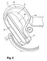
- FIGS. 2 , 3 , 5 and 6 show views schematically representing in perspective a device for generating a mixed air flow participating in the installation and equipped with the dispensing shutter respectively illustrated in the open and closed position.
- figures 5 and 6 are enlarged views of the present invention respectively detailed at figures 2 and 3 .
- the installation 1 is shown schematically in perspective in which the distribution channel 18 has been removed.
- the mixing chamber 10 is advantageously equipped with at least one mixed air outlet 16 which is formed through a casing 17 delimiting the mixing chamber 10 and constituting the casing 2.
- Such a location of the outlet d Mixed air 16 limits the overall size of the installation 1 and gives the installation 1 improved compactness.
- such a location makes it possible to easily place aerated communication air outlet 16 mixed with the air distribution channel 18, visible on the figure 1 , in an area of the facility 1 easily accessible.
- the distribution channel 18 is likely to have a simple conformation, preferably predominantly rectilinear, which tends to reduce the pressure losses experienced by the mixed air flow conveyed by the distribution channel 18 while ensuring an overall compactness optimized.
- the mixed air outlet 16 is equipped with a distribution flap 19 which is rotatable on itself between an open position, represented on the figures 2 and 5 , in which it allows a flow of air through the mixed air outlet 16 to the distribution channel 18 and a closed position, shown in FIGS. figures 3 and 6 in which it prohibits air circulation through the mixed air outlet 16.
- the distribution flap 19 consists of a wall 20. It is rotatable about a hinge member 21.
- the hinge element 21 of the distribution flap 19, for example an axis, is articulated on the envelope 17 delimiting the mixing chamber 10.
- the distribution flap 19 is articulated in the distribution channel 18 which is in aeraulic relationship with a discharge outlet 40 of the mixed air flow provided at through the envelope 17.
- the installation 1 is schematically represented in perspective the installation as detailed on the figures 2 and 3 in which the distribution flap 19 has been removed.
- the mixing chamber 10 houses a mixing flap 22 movable between two extreme positions. In a first extreme position, the mixing flap 22 closes an inlet mouth of the cold air flow formed through the casing 17. In a second extreme position, the mixing flap 22 closes an inlet mouth of the flow of hot air formed through the casing 17.
- the inlet of the cold air flow is an air passage for the first fraction of air flow admitted directly inside a mixing chamber While the inlet mouth of the hot air flow constitutes an air passage for the second fraction of air flow admitted inside a heating chamber 12.
- the mixing flap 22 is articulated on the housing 2 via an axis of rotation 25.
- the mixing flap 22 comprises at least one flange 30 constituting a connection between the axis of rotation 25 and a closure wall 28 of the mixing flap 22.
- the closure wall 28 is intended to at least partially close one of the inlet mouths of the cold air flow and / or the hot air flow, so as to generate a flow mixed air whose temperature may range between that of the first fraction of cold air flow and that of the second fraction of air flow admitted inside a heating chamber 12.
- the mixing flap 22 comprises two lateral flanges 30 between which a medial flange 31 is interposed.
- the lateral flanges 30 are arranged at a distance from one another. distance D of a respective extreme edge 32 of the mixing flap 22.
- This offset of the side flanges 30 towards the inside of the mixing flap 22 allows to provide a lateral passage 33 in which each of the distribution flaps 19 is able to be movable in rotation around the hinge member 21.
- the distribution flaps 19 are moved in the lateral passage 33 of the mixing flap 22.
- the distance D between the flange 30 and the end edge 32 of the mixing flap 22 is between 10% and 30% of a length L of the mixing flap.
- the figure 8 differs from the example described in figure 7 by the position of the mixing flap 22.
- the mixing flap 22 has been rotated clockwise about the axis 25 relative to the position which was its own. figure 7 .
- the position of the distribution flaps 19 in figures 7 and 8 has not been modified.
- the geometry of the distribution flaps 19 and the presence of side passages 33 in the mixing flap 22 allow the movement of the mixing flap 22 without interfering with the distribution flaps 19.
- the lateral flanges 30 are respectively formed of two connecting arms 34 between the axis of rotation 25 and the closure wall 28. These link arms 34 delimit together with the closure wall 28 a recess 35 for the passage of the mixed air flow.
- the figures 9 and 10 show also the possibility of moving the distribution flaps 19 and the mixing flap 22 around their respective rotational axes 25 and AB without the distribution flaps 19 interfere with the mixing flap 22 and vice versa.
- the distribution flaps 19 are, for a first, in the closed position and, for a second, in the open position.
- the first distribution flap to rotate about its axis of rotation AB to come into open position while the second distribution flap to rotate about its axis of rotation AB to come into closed position.
- the mixing flap 22 has rotated clockwise about its axis of rotation 25 between the arrangements described respectively in FIGS. figures 9 and 10 .
- the wall 20 of the distribution flap 19 is preferably flat and has a clearance 38 allowing the passage of the axis of rotation 25 of the mixing flap 22.
- the wall 20 of the distribution flap 19 is preferably flat and is delimited by a peripheral periphery 36 which has two points of inflection P and P '. These two points of inflection P and P 'delimit the clearance 38.
- the peripheral periphery 36 is constituted by the first curve C1 and a second curve C2 which comprises three curve portions PC2 which are each formed of a respective arc of a circle. Two successive PC2 curve portions are connected together by a straight portion 37.
- the length of the curve C2 is preferably greater than twice the length of the curve C1.
- the hinge element 21 of the distribution flap 19 has two common points A, B with the second curve C2.
- the first curve C1 delimits a clearance 38 opening at the periphery 36, this clearance 38 being formed through the dispensing flap 19 to allow rotational mobility of the dispensing flap 19 despite the presence in the vicinity of the flap.
- This clearance 38 advantageously allows to combine the cold and hot air flow mixing functions of the mixing flap 22 and distribution of a mixed air flow by the distribution flap 19 within the most limited possible space.
- the object of the present invention as described in connection with the various examples detailed above is to provide a device for dispensing a mixed air flow comprising a mixing chamber housing a mixing flap and at least one distribution flap arranged in a compact, simple and satisfactory manner with regard to the operation and performance of the installation.
- the present invention finds particular application in heating, ventilation and / or air conditioning systems and in particular in the field of motor vehicle equipment.
Landscapes
- Physics & Mathematics (AREA)
- Thermal Sciences (AREA)
- Engineering & Computer Science (AREA)
- Mechanical Engineering (AREA)
- Air-Conditioning For Vehicles (AREA)
- Instructional Devices (AREA)
- Luminescent Compositions (AREA)
- Air-Flow Control Members (AREA)
Abstract
Description
La présente invention est du domaine des installations de chauffage, de ventilation et/ou de climatisation, notamment d'un véhicule automobile. Elle a pour objet un volet de distribution intégré dans une telle installation, un dispositif de génération d'un flux d'air mixé équipé d'un tel volet de distribution ainsi qu'une installation logeant un tel dispositif.The present invention is in the field of heating, ventilation and / or air conditioning, in particular a motor vehicle. It relates to an integrated distribution flap in such an installation, a device for generating a mixed air flow equipped with such a distribution flap and an installation housing such a device.
Un dispositif de mixage comprenant un volet est connu du document
Un véhicule automobile est couramment équipé d'une installation de chauffage, de ventilation et/ou de climatisation qui est destinée à réguler la température de l'air contenu à l'intérieur de l'habitacle du véhicule. L'installation comprend un boîtier délimité par une cloison à travers laquelle sont ménagées des ouvertures, dont au moins une entrée d'air et au moins une sortie d'air. Le boîtier loge un pulseur ou groupe moto-ventilateur pour faire circuler un flux d'air depuis l'entrée d'air vers la sortie d'air et des moyens de traitement thermique du flux d'air pour réchauffer et/ou refroidir le flux d'air préalablement à sa distribution à l'intérieur de l'habitacle à travers la sortie d'air. Les moyens de traitement thermique du flux d'air comprennent un évaporateur qui est, notamment, destiné à refroidir le flux d'air qui le traverse et un radiateur, éventuellement associé à un radiateur additionnel, notamment électrique constitués d'une série de résistances électriques, qui est destiné à réchauffer le flux d'air qui le traverse.A motor vehicle is commonly equipped with a heating, ventilation and / or air conditioning system which is intended to regulate the temperature of the air contained inside the passenger compartment of the vehicle. The installation comprises a housing delimited by a partition through which openings are provided, including at least one air inlet and at least one air outlet. The housing houses a blower or motor-fan unit for circulating a flow of air from the air inlet to the air outlet and means for heat treatment of the air flow to heat and / or cool the flow of air prior to distribution inside the passenger compartment through the air outlet. The means for heat treatment of the air flow comprise an evaporator which is, in particular, intended to cool the flow of air passing therethrough and a radiator, possibly associated with an additional radiator, notably electrical consisting of a series of electrical resistors. which is intended to heat the flow of air passing through it.
Plus précisément, l'évaporateur est placé après l'entrée d'air du boîtier de sorte que la totalité du flux d'air entrant soit refroidi. Une fraction du flux d'air refroidi est réchauffée par le radiateur. Le boîtier comporte un dispositif apte à générer un flux d'air mixé à partir du flux d'air refroidi et du flux d'air réchauffé. Ce dispositif comprend une chambre de mixage d'un flux d'air froid issu du flux d'air refroidi et d'un flux d'air chaud issu du flux d'air réchauffé. La chambre de mixage est délimitée par une enveloppe constitutive du boîtier. Cette enveloppe est pourvue d'une bouche d'admission du flux d'air froid, d'une bouche d'admission du flux d'air chaud et d'au moins une bouche d'évacuation du flux d'air mixé. La chambre de mixage constitue une enceinte à l'intérieur de laquelle un volet de mixage est mobile entre une première position dans laquelle il obture la bouche d'admission du flux d'air froid, et une deuxième position dans laquelle il obture la bouche d'admission du flux d'air chaud à l'intérieur de la chambre de mixage. Lorsque le volet de mixage est placé en une position intermédiaire entre la première et la deuxième position, il autorise le passage simultané d'un flux d'air froid et d'un flux d'air chaud en proportions respectives variables pour générer un flux d'air mixé à l'intérieur de la chambre de mixage.Specifically, the evaporator is placed after the air inlet of the housing so that all of the incoming air flow is cooled. A fraction of the cooled air stream is heated by the radiator. The housing comprises a device capable of generating a mixed air flow from the cooled air flow and the heated air flow. These measures comprises a mixing chamber of a cold air flow from the cooled air flow and a hot air flow from the heated air flow. The mixing chamber is delimited by a casing constituting the housing. This envelope is provided with a cold air intake inlet, an inlet of the hot air flow and at least one outlet of the mixed air flow. The mixing chamber constitutes an enclosure inside which a mixing flap is movable between a first position in which it closes the inlet mouth of the cold air flow, and a second position in which it closes the mouth of admission of the hot air flow inside the mixing chamber. When the mixing flap is placed in an intermediate position between the first and the second position, it allows the simultaneous passage of a cold air flow and a hot air flow in respective variable proportions to generate a flow of air. mixed air inside the mixing chamber.
Un tel volet de mixage est par exemple du type 'tambour' mobile en rotation autour d'un axe. Dans ce cas, le volet de mixage comprend une paroi d'obturation conformée en une portion de cylindre constituant un organe d'obturation de la bouche d'admission du flux d'air froid et/ou de la bouche d'admission du flux d'air chaud. La paroi d'obturation est reliée à l'axe de rotation du volet de mixage par l'intermédiaire de flasques, en particulier conformés en une portion de disque circulaire.Such mixing flap is for example of the type 'drum' mobile in rotation about an axis. In this case, the mixing flap comprises a closure wall shaped as a cylinder portion constituting a shutter member of the intake port of the cold air flow and / or the inlet of the flow of air. 'hot air. The closure wall is connected to the axis of rotation of the mixing flap via flanges, in particular shaped as a circular disk portion.
Le boîtier est pourvu d'au moins une sortie d'air mixé équipée d'un volet de distribution. Ce volet de distribution est manoeuvrable entre une position d'ouverture dans laquelle il autorise une circulation d'air à travers la sortie d'air et une position de fermeture dans laquelle il interdit une telle circulation. Un canal de distribution d'air est en communication aéraulique avec la sortie d'air mixé pour acheminer le flux d'air mixé vers une zone spécifique de l'habitacle, telle qu'une zone avant et/ou une zone arrière, une zone droite et/ou une zone gauche, une zone de pied, voire une zone définie par une quelconque combinaison de ces critères. Le volet de distribution est indifféremment articulé sur le boîtier ou dans le canal de distribution. Pour connaître un environnement technologique de la présente invention, on pourra par exemple se reporter au document
Le volet de distribution est principalement constitué d'une paroi délimitée par un pourtour périphérique qui est d'une conformation semblable à celle de la sortie d'air mixé. En d'autres termes, la paroi est apte à s'inscrire à l'intérieur de l'ouverture formant la sortie d'air mixé pour obturer cette dernière. Pour ce faire, la paroi est mobile en rotation sur elle-même autour d'un élément d'articulation qu'il comporte, de telle sorte que le volet de distribution puisse être placé en une quelconque position comprise entre sa position d'ouverture et sa position de fermeture.The distribution flap consists mainly of a wall delimited by a peripheral periphery which is of a conformation similar to that of the mixed air outlet. In other words, the wall is able to register inside the opening forming the mixed air outlet to close the latter. To do this, the wall is rotatable about itself around a hinge element that it comprises, so that the distribution flap can be placed in any position between its open position and its closing position.
D'une manière générale, une telle installation s'avère volumineuse et les modalités de raccordement du canal de distribution d'air avec la sortie d'air mixé sont complexes et engendrent un accroissement de l'encombrement global de l'installation. Plus particulièrement, une telle sortie d'air mixé est fréquemment placée en une zone difficilement accessible de l'installation de sorte que le canal de distribution présente une conformation complexe, généralement source de pertes de charge pour le flux d'air mixé véhiculé par le canal de distribution. Par ailleurs, l'espace alloué à une telle sortie d'air peut être réduit. Il en découle que ce canal est susceptible de présenter une section d'autant plus réduite. Ceci n'est pas satisfaisant au regard du fonctionnement et du rendement de l'installation. Il en ressort finalement qu'un tel volet de distribution mérite d'être amélioré pour permettre une mise en communication aéraulique aisée et rapide du canal de distribution avec la sortie d'air mixé correspondante.In general, such an installation is bulky and the terms of connection of the air distribution channel with the mixed air outlet are complex and cause an increase in the overall size of the installation. More particularly, such a mixed air outlet is frequently placed in an inaccessible zone of the installation so that the distribution channel has a complex conformation, generally source of pressure losses for the mixed air flow conveyed by the distribution channel. Moreover, the space allocated to such an air outlet can be reduced. It follows that this channel is likely to have a smaller section. This is not satisfactory with regard to the operation and performance of the installation. It finally emerges that such a distribution component deserves to be improved in order to enable easy and rapid aeraulic communication of the distribution channel with the corresponding mixed air outlet.
Un premier but de la présente invention est de proposer un volet de distribution qui soit apte à équiper une installation de chauffage, de ventilation et/ou de climatisation d'un véhicule automobile en étant disposé en un quelconque endroit de cette dernière et notamment à proximité d'un élément structurel que celle-ci comporte.A first object of the present invention is to provide a distribution flap which is adapted to equip a heating, ventilation and / or air conditioning of a motor vehicle being disposed in any place of the latter and in particular near a structural element that it comprises.
Un deuxième but de la présente invention est de proposer un dispositif de génération d'un flux d'air mixé équipé d'un tel volet de distribution dont la compacité soit la plus importante possible.A second object of the present invention is to provide a device for generating a mixed air flow equipped with such a distribution flap whose compactness is the largest possible.
Un troisième but de la présente invention est de proposer une installation de chauffage, de ventilation et/ou de climatisation permettant une diffusion d'un flux d'air efficace et pérenne d'une zone de l'habitacle du véhicule à partir d'un flux d'air mixé dont les pertes de charge sont réduites au maximum, ce flux d'air mixé étant véhiculé par un canal de distribution dont la conformation est simple, préférentiellement rectiligne.A third object of the present invention is to provide a heating, ventilation and / or air conditioning system for diffusing an effective and lasting air flow of an area of the passenger compartment of the vehicle from a mixed air flow whose pressure losses are reduced to the maximum, this mixed air flow being conveyed by a distribution channel whose conformation is simple, preferably rectilinear.
Un quatrième but de la présente invention est de proposer une telle installation qui permette de surcroit d'aérer avec les meilleures performances thermiques possible une zone de l'habitacle requérant un flux d'air mixé relativement plus chaud ou plus froid que d'autres flux d'air sortant de l'installation..A fourth object of the present invention is to provide such an installation which also allows airing with the best thermal performance possible a cabin area requiring a mixed air flow relatively hotter or colder than other flows of air leaving the installation ..
Pour ce faire, la présente invention propose un dispositif de génération d'un flux d'air mixé comportant une chambre de mixage logeant un volet de mixage, et comprenant au moins un volet de distribution mobile en rotation autour d'un élément d'articulation. Le volet de mixage comporte un passage latéral permettant la rotation du volet de distribution.To do this, the present invention provides a device for generating a mixed air flow comprising a mixing chamber housing a mixing flap, and comprising at least one distribution flap rotatable around a hinge element. . The mixing flap comprises a lateral passage allowing rotation of the distribution flap.
La forme du volet est dépendante de la disposition de la zone d'une bouche d'évacuation et de sa localisation dans l'installation de chauffage, de ventilation et/ou de climatisation.The shape of the flap is dependent on the disposition of the area of a vent and its location in the heating, ventilation and / or air conditioning system.
Selon une variante de la présente invention, le volet de mixage comporte une paroi d'obturation, un axe de rotation et au moins un flasque formant une liaison entre la paroi d'obturation et l'axe de rotation du volet de mixage.According to a variant of the present invention, the mixing flap comprises a closure wall, an axis of rotation and at least one flange forming a connection between the closure wall and the axis of rotation of the mixing flap.
Alternativement, le flasque est disposé à une distance D d'un bord extrême du volet de mixage ménageant le passage latéral entre le bord extrême et le flasque du volet de mixage.Alternatively, the flange is disposed at a distance D from an extreme edge of the mixing flap providing the lateral passage between the extreme edge and the flange of the mixing flap.
Selon la présente invention, le volet de mixage et les volets de distribution évoluent dans la même zone de l'installation de chauffage, de ventilation et/ou de climatisation. Plus particulièrement, le volet de mixage ne comprend pas de flasques qui soient disposés aux extrémités du volet de mixage. Ainsi, l'espace disponible permet de loger le volet de distribution.According to the present invention, the mixing flap and the distribution flaps operate in the same area of the heating, ventilation and / or air conditioning system. More particularly, the mixing flap does not include flanges that are arranged at the ends of the mixing flap. Thus, the available space makes it possible to house the distribution flap.
L'élément d'articulation du volet de distribution est préférentiellement orthogonal à l'axe de rotation du volet de mixage.The hinge element of the distribution flap is preferably orthogonal to the axis of rotation of the mixing flap.
Néanmoins, selon diverses variantes de réalisation, l'élément d'articulation du volet de distribution est agencé en fonction de l'architecture de l'installation de chauffage, de ventilation et/ou de climatisation. Ainsi, l'axe de rotation du volet de mixage et l'élément d'articulation du volet de distribution peuvent donc être orthogonaux entre eux, parallèles entre eux ou alors agencés dans des directions différentes.Nevertheless, according to various alternative embodiments, the hinge element of the distribution flap is arranged according to the architecture of the heating, ventilation and / or air conditioning system. Thus, the axis of rotation of the mixing flap and the articulation element of the distribution flap can therefore be orthogonal to each other, parallel to each other or else arranged in different directions.
L'élément d'articulation du volet de distribution est articulé sur une enveloppe délimitant la chambre de mixage ou sur un canal de distribution du flux d'air mixé.The articulation element of the distribution flap is articulated on an envelope delimiting the mixing chamber or on a distribution channel of the mixed air flow.
De façon préférentielle, le canal de distribution du flux d'air mixé est en relation aéraulique avec une bouche d'évacuation du flux d'air mixé ménagée à travers l'enveloppe.Preferably, the distribution channel of the mixed air flow is in aeration relationship with a discharge outlet of the mixed air flow formed through the casing.
Ces dispositions sont telles que le canal de distribution est apte à être exploité pour aérer une zone spécifique de l'habitacle du véhicule, telle qu'une zone d'aération avant, une zone de pied avant, une zone de pied arrière ou une zone arrière. La liaison aéraulique entre le canal de distribution et l'enveloppe est ménagée en une zone aisément accessible de telle sorte que le canal de distribution présente une conformation globale simple, préférentiellement rectiligne, et en tout état de cause exempte de variations de géométries brusques génératrices de pertes de charge pour le flux d'air mixé véhiculé par le canal de distribution.These provisions are such that the distribution channel is adapted to be operated to ventilate a specific area of the passenger compartment of the vehicle, such as a front ventilation zone, a front foot zone, a rear foot zone or a zone back. The aeraulic link between the distribution channel and the envelope is arranged in an easily accessible zone so that the distribution channel has a simple overall configuration, preferably rectilinear, and in any case free of sudden variations in geometries generating pressure losses for the mixed air flow conveyed by the distribution channel.
La bouche d'évacuation du flux d'air mixé est susceptible d'être disposée à proximité d'une bouche d'admission d'un flux d'air chaud ménagée à travers l'enveloppe de telle sorte que le flux d'air mixé véhiculé par l'intermédiaire du canal de distribution puisse aérer une zone de l'habitacle du véhicule requérant une aération fréquemment plus chaude que d'autres zones, telle qu'une zone de pied arrière ou avant.The outlet mouth of the mixed air flow is likely to be disposed near an inlet mouth of a flow of hot air formed through the casing so that the mixed air flow transported through the dispensing channel can ventilate an area of the passenger compartment of the vehicle requiring ventilation that is frequently hotter than other areas, such as a back or front foot zone.
Alternativement, la bouche d'évacuation du flux d'air mixé est susceptible d'être disposée à proximité d'une bouche d'admission d'un flux d'air froid ménagée à travers l'enveloppe de telle sorte que le flux d'air mixé véhiculé par l'intermédiaire du canal de distribution puisse aérer une zone de l'habitacle du véhicule requérant une aération fréquemment plus froide que d'autres zones.Alternatively, the outlet mouth of the mixed air flow is likely to be disposed near an inlet mouth of a cold air flow formed through the casing so that the flow of air mixed air conveyed through the distribution channel may ventilate an area of the passenger compartment of the vehicle requiring aeration frequently cooler than other areas.
De préférence, le flasque est formé d'au moins deux bras de liaison entre l'axe de rotation et la paroi d'obturation du volet de mixage, qui, selon une variante de réalisation, délimitent conjointement avec la paroi d'obturation un évidement pour un passage du flux d'air mixé.Preferably, the flange is formed of at least two connecting arms between the axis of rotation and the shutter wall of the mixing flap, which, according to an alternative embodiment, define together with the closure wall a recess for a passage of the mixed air flow.
Selon la présente invention, un exemple particulier de réalisation du volet de distribution consiste en ce que le volet comporte une paroi comprenant un dégagement apte à constituer un passage pour l'axe de rotation du volet de mixage. En particulier, la paroi est délimitée par un pourtour périphérique comportant deux points d'inflexion délimitant le dégagement.According to the present invention, a particular embodiment of the distribution flap consists in that the flap comprises a wall comprising a clearance adapted to constitute a passage for the axis of rotation of the mixing flap. In particular, the wall is delimited by a peripheral periphery comprising two points of inflection delimiting the clearance.
Le dégagement prévu dans la proi est délimité par une première courbe C1. Ce dégagement constitue un passage pour un obstacle placé sur la trajectoire du volet de distribution lors de la rotation sur lui-même. Il en ressort finalement qu'un tel volet de distribution est susceptible d'être installé en un quelconque endroit d'une installation de chauffage, de ventilation et/ou de climatisation, et notamment au plus près d'un élément structurel que comprend cette dernière. Il en découle que la compacité globale de l'installation est améliorée de façon conséquente. Par ailleurs, la présence d'un tel dégagement permet une économie de matière pour la réalisation du volet de distribution et lui confère une aisance de réalisation, par moulage notamment.The clearance provided in the proi is delimited by a first curve C1. This clearance constitutes a passage for an obstacle placed on the trajectory of the distribution flap when rotating on itself. It finally emerges that such a distribution flap is likely to be installed anywhere in a heating, ventilation and / or air conditioning installation, and in particular closer to a structural element that includes the latter. . It follows that the overall compactness of the installation is significantly improved. Moreover, the presence of such a clearance allows a saving of material for the realization of the dispensing flap and gives it an ease of production, particularly by molding.
Ainsi, selon la présente invention, le volet de distribution et le volet de mixage sont aptes à être disposés à proximité l'un de l'autre, le dégagement du volet de distribution constituant un passage pour l'axe de rotation du volet de mixage. Il en ressort une meilleure compacité du dispositif de génération du flux d'air mixé qui procure de surcroît une fonction de distribution du flux d'air mixé. La combinaison des fonctions de mixage et de distribution telle que présentée dans la présente invention permet d'obtenir une installation la plus compacte possible.Thus, according to the present invention, the distribution flap and the mixing flap are able to be arranged close to each other, the release of the distribution flap constituting a passage for the axis of rotation of the mixing flap. . This results in a better compactness of the device for generating the mixed air flow which additionally provides a distribution function of the mixed air flow. The combination of the mixing and dispensing functions as presented in the present invention makes it possible to obtain the most compact installation possible.
Une installation de chauffage, de ventilation et/ou de climatisation selon l'invention est principalement reconnaissable en ce qu'elle loge un tel dispositif de génération d'un flux d'air mixé.A heating, ventilation and / or air conditioning system according to the invention is mainly recognizable in that it houses such a device for generating a mixed air flow.
La présente invention sera mieux comprise, et des détails apparaîtront, à la lecture de la description qui va être faite de diverses formes de réalisation données à titre d'exemple et détaillées dans les figures des planches annexées, dans lesquelles :
- La
figure 1 représente schématiquement en perspective une installation de chauffage, de ventilation et/ou de climatisation selon la présente invention. - La
figure 2 représente schématiquement en perspective l'installation illustrée sur la figure précédente dans laquelle un canal de distribution a été enlevé, un volet de distribution intégré à l'installation étant disposé en position d'ouverture. - La
figure 3 représente schématiquement en perspective l'installation illustrée sur la figure précédente, le volet de distribution intégré à l'installation étant disposé en position de fermeture. - La
figure 4 représente schématiquement en perspective l'installation représentée sur lesfigures 2 et 3 dans laquelle le volet de distribution a été enlevé. - Les
figures 5 et 6 représentent schématiquement en perspective un dispositif de génération d'un flux d'air mixé participant de l'installation et équipé du volet de distribution respectivement illustré en position d'ouverture et de fermeture. - Les
figures 7 à 10 représentent schématiquement en perspective un volet de mixage et des volets de distribution intégré au dispositif de génération d'un flux d'air mixé illustré sur lesfigures 5 et 6 .
- The
figure 1 schematically shows in perspective a heating, ventilation and / or air conditioning system according to the present invention. - The
figure 2 schematically represents in perspective the installation illustrated in the previous figure in which a distribution channel has been removed, a distribution flap integrated in the installation being disposed in the open position. - The
figure 3 schematically represents in perspective the installation illustrated in the previous figure, the integrated distribution flap in the installation being arranged in the closed position. - The
figure 4 schematically represents in perspective the installation represented on thefigures 2 and3 in which the dispensing flap has been removed. - The
figures 5 and6 schematically represent in perspective a device for generating a mixed air flow participating in the installation and equipped with the dispensing shutter respectively illustrated in the open and closed position. - The
Figures 7 to 10 schematically show in perspective a mixing flap and distribution flaps integrated to the device for generating a mixed air flow illustrated on thefigures 5 and6 .
Sur les
Les
Sur les
La sortie d'air mixé 16 est équipée d'un volet de distribution 19 qui est mobile en rotation sur lui-même entre une position d'ouverture, représentée sur les
Le volet de distribution 19 est constitué d'une paroi 20. Il est mobile en rotation autour d'un élément d'articulation 21. L'élément d'articulation 21 du volet de distribution 19, par exemple un axe, est articulé sur l'enveloppe 17 délimitant la chambre de mixage 10. Selon une autre forme de réalisation, le volet de distribution 19 est articulé dans le canal de distribution 18 qui est en relation aéraulique avec une bouche d'évacuation 40 du flux d'air mixé ménagée à travers l'enveloppe 17.The
Sur la
Le volet de mixage 22 est articulé sur le boîtier 2 par l'intermédiaire d'un axe de rotation 25. Le volet de mixage 22 comporte au moins un flasque 30 constituant une liaison entre l'axe de rotation 25 et une paroi d'obturation 28 du volet de mixage 22. La paroi d'obturation 28 est destinée à obturer au moins partiellement l'une des bouches d'admission du flux d'air froid et/ou du flux d'air chaud, de manière à générer un flux d'air mixé dont la température peut s'échelonner entre celle de la première fraction de flux d'air froid et celle de la deuxième fraction de flux d'air admise à l'intérieur d'une chambre de chauffage 12.The mixing
Sur les
Préférentiellement, la distance D entre le flasque 30 et le bord extrême 32 du volet de mixage 22 est comprise entre 10% et 30% d'une longueur L du volet de mixage.Preferably, the distance D between the
La
Sur la variante de réalisation illustrée sur la
Les
En
Sur l'ensemble des déplacements, les volets de distribution 19 et le volet de mixage 22, bien que se trouvant dans des espaces communs, ne sont pas en contact l'un avec l'autre et ainsi n'interagissent pas les uns avec les autres.On all movements, the distribution flaps 19 and the mixing
De façon préférentielle, la paroi 20 du volet de distribution 19 est préférentiellement plane et comporte un dégagement 38 permettant le passage de l'axe de rotation 25 du volet de mixage 22.Preferably, the
Selon un exemple particulier de réalisation des volets de distribution tels que décrit en
Plus particulièrement, les deux points d'inflexion P et P' délimitent le dégagement 38 par une première courbe C1 qui comprend au moins une portion de courbe PC1 dont le centre de courbure O1 est situé à l'extérieur du pourtour périphérique 36.More particularly, the two inflection points P and P 'delimit the
Le pourtour périphérique 36 est constitué par la première courbe C1 et une deuxième courbe C2 qui comprend trois portions de courbe PC2 qui sont chacune formées d'un arc de cercle respectif. Deux portions de courbe PC2 successives sont reliées entre elles par une portion de droite 37. La longueur de la courbe C2 est de préférence supérieure au double de la longueur de la courbe C1. On notera par ailleurs que l'élément d'articulation 21 du volet de distribution 19 comporte deux points communs A, B avec la deuxième courbe C2.The
Ces dispositions sont telles que la première courbe C1 délimite un dégagement 38 débouchant au pourtour périphérique 36, ce dégagement 38 étant ménagé à travers le volet de distribution 19 pour autoriser une mobilité en rotation du volet de distribution 19 malgré la présence à proximité du volet de distribution 19 d'un élément structurel de l'installation 1, tel que l'axe de rotation 25 du volet de mixage 22. Ce dégagement 38 permet avantageusement de combiner les fonctions de mixage de flux d'air froid et chaud du volet de mixage 22 et de distribution d'un flux d'air mixé par le volet de distribution 19 à l'intérieur d'un espace le plus limité possible.These arrangements are such that the first curve C1 delimits a
L'objet de la présente invention telle que décrit en relation avec les différents exemples détaillés précédemment est de réaliser un dispositif de distribution d'un flux d'air mixé comportant une chambre de mixage logeant un volet de mixage et au moins un volet de distribution agencés de façon compacte, simple et satisfaisante au regard du fonctionnement et du rendement de l'installation.The object of the present invention as described in connection with the various examples detailed above is to provide a device for dispensing a mixed air flow comprising a mixing chamber housing a mixing flap and at least one distribution flap arranged in a compact, simple and satisfactory manner with regard to the operation and performance of the installation.
La présente invention trouve une application particulière dans les installations de chauffage, ventilation et/ou climatisation et en particulier dans le domaine des équipements des véhicules automobiles.The present invention finds particular application in heating, ventilation and / or air conditioning systems and in particular in the field of motor vehicle equipment.
Bien évidemment, l'invention n'est pas limitée aux modes de réalisation décrits précédemment et fournis uniquement à titre d'exemple et englobe d'autres variantes que pourra envisager l'homme du métier dans le cadre des revendications et notamment toutes combinaisons des différents modes de réalisation décrits précédemment.Obviously, the invention is not limited to the embodiments described above and provided solely by way of example and encompasses other variants that may be considered by those skilled in the art within the scope of the claims and in particular any combination of different embodiments described above.
Claims (12)
- Device for distributing a mixed airflow comprising a mixing chamber (10) housing a mixing flap (22) and comprising at least one distribution flap (19) movable in rotation about an articulation element (21) between an open position in which it allows air to circulate through an air outlet and a closed position in which it prevents such circulation, characterized in that the mixing flap (22) comprises a lateral passage (33) allowing the distribution flap (19) to rotate.
- Device for generating a mixed airflow according to Claim 1, characterized in that the mixing flap (22) comprises a shut-off wall (28), a rotation axle (25) and at least one flange (30, 31) forming a connection between the shut-off wall (28) and the rotation axle (25) of the mixing flap (22).
- Device for generating a mixed airflow according to Claim 2, characterized in that the flange (30, 31) is positioned a distance D away from an end edge (32) of the mixing flap (22) creating the lateral passage (33) between the end edge (32) and the flange (30, 31) of the mixing flap (22).
- Device for generating a mixed airflow according to Claim 2 or 3, characterized in that the articulation element (21) of the distribution flap (19) is orthogonal to the rotation axle (25) of the mixing flap (22).
- Device for generating a mixed airflow according to any one of the preceding claims, characterized in that the articulation element (21) of the distribution flap (19) is articulated to a casing (17) delimiting the mixing chamber (17).
- Device for generating a mixed airflow according to any one of the preceding claims, characterized in that the articulation element (21) of the distribution flap (19) is articulated to a distribution duct (18) for distributing the mixed airflow.
- Device for generating a mixed airflow according to Claim, characterized in that the distribution duct (18) for distributing the mixed airflow is in aeraulic communication with an outlet (40) for discharging the mixed airflow, which outlet is formed through the casing (17).
- Device for generating a mixed airflow according to any one of Claims 2 to 7, characterized in that the flange (30, 31) comprises at least two connecting arms (34) between the rotation axle (25) and the shut-off wall (28).
- Device for generating a mixed airflow according to Claim 8, characterized in that the connecting arms (34) of the flange (30, 31) delimit together with the shut-off wall (28) a recess (35) for the passage of the mixed airflow.
- Device for generating a mixed airflow according to one of Claims 2 to 9, characterized in that the distribution flap (19) for distributing an airflow comprises a wall (20) that has a cut-out (38) able to form a passage for the rotation axle (25) of the mixing flap (22).
- Device for generating a mixed airflow according to Claim 10, characterized in that the wall (20) is delimited by a peripheral perimeter (36) comprising two points of inflexion (P, P') delimiting the cut-out (38).
- Heating, ventilating and/or air conditioning system housing a device for generating a mixed airflow according to any one of the preceding claims.
Applications Claiming Priority (1)
| Application Number | Priority Date | Filing Date | Title |
|---|---|---|---|
| FR0706065A FR2920511B1 (en) | 2007-08-29 | 2007-08-29 | DEVICE FOR DISPENSING A MIXED AIR FLOW, IN PARTICULAR FOR A HEATING, VENTILATION AND / OR AIR CONDITIONING INSTALLATION OF A MOTOR VEHICLE |
Publications (2)
| Publication Number | Publication Date |
|---|---|
| EP2030818A1 EP2030818A1 (en) | 2009-03-04 |
| EP2030818B1 true EP2030818B1 (en) | 2010-03-10 |
Family
ID=39233079
Family Applications (1)
| Application Number | Title | Priority Date | Filing Date |
|---|---|---|---|
| EP08162962A Active EP2030818B1 (en) | 2007-08-29 | 2008-08-26 | Mixed air flow directing device, in particular for a heating, ventilating and/or air conditioning system of a vehicle |
Country Status (5)
| Country | Link |
|---|---|
| EP (1) | EP2030818B1 (en) |
| AT (1) | ATE460300T1 (en) |
| DE (1) | DE602008000780D1 (en) |
| ES (1) | ES2340447T3 (en) |
| FR (1) | FR2920511B1 (en) |
Cited By (1)
| Publication number | Priority date | Publication date | Assignee | Title |
|---|---|---|---|---|
| DE102019128461A1 (en) * | 2019-10-22 | 2021-04-22 | Mann+Hummel Gmbh | Flow system for fluids with a switching device |
Families Citing this family (3)
| Publication number | Priority date | Publication date | Assignee | Title |
|---|---|---|---|---|
| JP4444347B2 (en) | 2008-05-29 | 2010-03-31 | 三菱重工業株式会社 | Air conditioner for vehicles |
| DE102010029297A1 (en) * | 2010-05-26 | 2011-12-01 | Behr Gmbh & Co. Kg | Plant for controlling at least two air streams |
| DE102010031475A1 (en) * | 2010-07-16 | 2012-01-19 | Behr Gmbh & Co. Kg | Air mixing door assembly |
Family Cites Families (5)
| Publication number | Priority date | Publication date | Assignee | Title |
|---|---|---|---|---|
| FR2800328B1 (en) * | 1999-10-27 | 2002-01-11 | Valeo Climatisation | IMPROVED DISTRIBUTION DEVICE OF AN AIR FLOW IN A VENTILATION, HEATING AND / OR AIR CONDITIONING SYSTEM OF A MOTOR VEHICLE |
| DE10127347A1 (en) * | 2001-06-06 | 2002-12-12 | Valeo Klimasysteme Gmbh | Mechanism for controlling air guides of car heater comprises control cylinders connected to central, motorized shaft which have guide grooves in which levers attached to guides move |
| FR2829064B1 (en) | 2001-08-30 | 2005-01-14 | Valeo Climatisation | DEVICE FOR GENERATION OF A FLOW OF AIR AT REGULATED TEMPERATURE FOR THE PASSENGER CABIN OF A MOTOR VEHICLE AND HEATING AND/OR AIR CONDITIONING APPARATUS COMPRISING THIS DEVICE |
| DE10161997A1 (en) * | 2001-12-18 | 2003-06-05 | Daimler Chrysler Ag | Air conditioning or heating unit has cold air control unit arranged so that as it moves to reduce aperture, its coverage of air inlet surface of heat exchanger is reduced |
| US8091623B2 (en) * | 2004-10-01 | 2012-01-10 | Behr Gmbh & Co. Kg | Air mixer vent |
-
2007
- 2007-08-29 FR FR0706065A patent/FR2920511B1/en not_active Expired - Fee Related
-
2008
- 2008-08-26 DE DE602008000780T patent/DE602008000780D1/en active Active
- 2008-08-26 ES ES08162962T patent/ES2340447T3/en active Active
- 2008-08-26 EP EP08162962A patent/EP2030818B1/en active Active
- 2008-08-26 AT AT08162962T patent/ATE460300T1/en not_active IP Right Cessation
Cited By (1)
| Publication number | Priority date | Publication date | Assignee | Title |
|---|---|---|---|---|
| DE102019128461A1 (en) * | 2019-10-22 | 2021-04-22 | Mann+Hummel Gmbh | Flow system for fluids with a switching device |
Also Published As
| Publication number | Publication date |
|---|---|
| ES2340447T3 (en) | 2010-06-02 |
| FR2920511A1 (en) | 2009-03-06 |
| EP2030818A1 (en) | 2009-03-04 |
| DE602008000780D1 (en) | 2010-04-22 |
| FR2920511B1 (en) | 2009-10-23 |
| ATE460300T1 (en) | 2010-03-15 |
Similar Documents
| Publication | Publication Date | Title |
|---|---|---|
| EP2709863B1 (en) | Heating, ventilation and/or air-conditioning apparatus including an air flow channel bypassing a heat exchanger | |
| EP2030818B1 (en) | Mixed air flow directing device, in particular for a heating, ventilating and/or air conditioning system of a vehicle | |
| EP1514707B1 (en) | Improved air temperature control of a passenger cell heating and/or air conditioning device | |
| EP2889168B1 (en) | Heating, ventilation and/or air conditioning device | |
| WO2018020105A1 (en) | Heating, ventilation and/or air conditioning device for a motor vehicle | |
| EP2243646B1 (en) | Thermal treatment box for thermal treatment of an air flow | |
| FR3054489A1 (en) | AIR FLOW CONTROL DEVICE FOR A HEATING, VENTILATION AND / OR AIR CONDITIONING DEVICE FOR A MOTOR VEHICLE | |
| EP2528758B1 (en) | Heating, ventilation and/or air conditioning system, in particular for an electric automobile vehicle | |
| FR2903345A1 (en) | DEVICE FOR PREVENTILATION, VENTILATION, HEATING AND / OR AIR CONDITIONING OF A VEHICLE HABITACLE UTILIZING A PULSER AND THERMOELECTRIC UNITS WITH PELTIER EFFECT | |
| EP3481655B1 (en) | Heating, ventilation and/or air conditioning device for a motor vehicle | |
| EP1514708B1 (en) | Heating and/or air conditioning device for vehicle compartment, with sophisticated aerothermic management | |
| EP2106941B1 (en) | Heating, ventilating and / or air conditioning apparatus for motor vehicle | |
| EP4135989A1 (en) | Heating, ventilation and/or air-conditioning device for a motor vehicle | |
| FR2795684A1 (en) | Air conditioner for motor vehicle interior has casing with mixing chamber feeding conditioned air to front of interior and fresh air to rear | |
| WO2021209409A1 (en) | Heating, ventilation and/or air-conditioning device for a motor vehicle | |
| WO2017162990A1 (en) | Air-conditioning housing for motor vehicle passenger compartment and air treatment system comprising such a housing | |
| FR2920110A1 (en) | Shutter's e.g. distribution shutter, implementation controlling device for ventilating, heating and air-conditioning installation of motor vehicle, has maneuver unit including cams respectively assigned to maneuver of shutters | |
| FR2814703A1 (en) | Air flow adjuster for vehicle climate control includes flaps fixed on shaft to direct several air flows to several air guide channels | |
| EP2836381B1 (en) | Device for the thermal conditioning of a vehicle passenger compartment | |
| WO2023175006A1 (en) | Motorised ventilation unit | |
| FR2863945A1 (en) | Thermal assembly for motor vehicle, has butterfly valve arranged in mixing zone for mixing and/or distributing air flow in direction of cab interior, and cross supporting beam supporting valve for mixing and/or distributing air flow | |
| FR3014027A1 (en) | HEATING, VENTILATION AND / OR AIR CONDITIONING INSTALLATION FOR A MOTOR VEHICLE | |
| FR3034047A1 (en) | DEVICE FOR HEATING, VENTILATION AND / OR AIR CONDITIONING FOR A MOTOR VEHICLE |
Legal Events
| Date | Code | Title | Description |
|---|---|---|---|
| PUAI | Public reference made under article 153(3) epc to a published international application that has entered the european phase |
Free format text: ORIGINAL CODE: 0009012 |
|
| AK | Designated contracting states |
Kind code of ref document: A1 Designated state(s): AT BE BG CH CY CZ DE DK EE ES FI FR GB GR HR HU IE IS IT LI LT LU LV MC MT NL NO PL PT RO SE SI SK TR |
|
| AX | Request for extension of the european patent |
Extension state: AL BA MK RS |
|
| 17P | Request for examination filed |
Effective date: 20090731 |
|
| GRAP | Despatch of communication of intention to grant a patent |
Free format text: ORIGINAL CODE: EPIDOSNIGR1 |
|
| AKX | Designation fees paid |
Designated state(s): AT BE BG CH CY CZ DE DK EE ES FI FR GB GR HR HU IE IS IT LI LT LU LV MC MT NL NO PL PT RO SE SI SK TR |
|
| GRAS | Grant fee paid |
Free format text: ORIGINAL CODE: EPIDOSNIGR3 |
|
| GRAA | (expected) grant |
Free format text: ORIGINAL CODE: 0009210 |
|
| AK | Designated contracting states |
Kind code of ref document: B1 Designated state(s): AT BE BG CH CY CZ DE DK EE ES FI FR GB GR HR HU IE IS IT LI LT LU LV MC MT NL NO PL PT RO SE SI SK TR |
|
| REG | Reference to a national code |
Ref country code: GB Ref legal event code: FG4D Free format text: NOT ENGLISH |
|
| REG | Reference to a national code |
Ref country code: CH Ref legal event code: EP |
|
| REG | Reference to a national code |
Ref country code: IE Ref legal event code: FG4D |
|
| REF | Corresponds to: |
Ref document number: 602008000780 Country of ref document: DE Date of ref document: 20100422 Kind code of ref document: P |
|
| REG | Reference to a national code |
Ref country code: ES Ref legal event code: FG2A Ref document number: 2340447 Country of ref document: ES Kind code of ref document: T3 |
|
| REG | Reference to a national code |
Ref country code: NL Ref legal event code: VDEP Effective date: 20100310 |
|
| PG25 | Lapsed in a contracting state [announced via postgrant information from national office to epo] |
Ref country code: LT Free format text: LAPSE BECAUSE OF FAILURE TO SUBMIT A TRANSLATION OF THE DESCRIPTION OR TO PAY THE FEE WITHIN THE PRESCRIBED TIME-LIMIT Effective date: 20100310 Ref country code: HR Free format text: LAPSE BECAUSE OF FAILURE TO SUBMIT A TRANSLATION OF THE DESCRIPTION OR TO PAY THE FEE WITHIN THE PRESCRIBED TIME-LIMIT Effective date: 20100310 Ref country code: NO Free format text: LAPSE BECAUSE OF FAILURE TO SUBMIT A TRANSLATION OF THE DESCRIPTION OR TO PAY THE FEE WITHIN THE PRESCRIBED TIME-LIMIT Effective date: 20100610 |
|
| LTIE | Lt: invalidation of european patent or patent extension |
Effective date: 20100310 |
|
| PG25 | Lapsed in a contracting state [announced via postgrant information from national office to epo] |
Ref country code: SI Free format text: LAPSE BECAUSE OF FAILURE TO SUBMIT A TRANSLATION OF THE DESCRIPTION OR TO PAY THE FEE WITHIN THE PRESCRIBED TIME-LIMIT Effective date: 20100310 Ref country code: PL Free format text: LAPSE BECAUSE OF FAILURE TO SUBMIT A TRANSLATION OF THE DESCRIPTION OR TO PAY THE FEE WITHIN THE PRESCRIBED TIME-LIMIT Effective date: 20100310 Ref country code: AT Free format text: LAPSE BECAUSE OF FAILURE TO SUBMIT A TRANSLATION OF THE DESCRIPTION OR TO PAY THE FEE WITHIN THE PRESCRIBED TIME-LIMIT Effective date: 20100310 Ref country code: LV Free format text: LAPSE BECAUSE OF FAILURE TO SUBMIT A TRANSLATION OF THE DESCRIPTION OR TO PAY THE FEE WITHIN THE PRESCRIBED TIME-LIMIT Effective date: 20100310 Ref country code: FI Free format text: LAPSE BECAUSE OF FAILURE TO SUBMIT A TRANSLATION OF THE DESCRIPTION OR TO PAY THE FEE WITHIN THE PRESCRIBED TIME-LIMIT Effective date: 20100310 |
|
| REG | Reference to a national code |
Ref country code: IE Ref legal event code: FD4D |
|
| PG25 | Lapsed in a contracting state [announced via postgrant information from national office to epo] |
Ref country code: EE Free format text: LAPSE BECAUSE OF FAILURE TO SUBMIT A TRANSLATION OF THE DESCRIPTION OR TO PAY THE FEE WITHIN THE PRESCRIBED TIME-LIMIT Effective date: 20100310 Ref country code: SE Free format text: LAPSE BECAUSE OF FAILURE TO SUBMIT A TRANSLATION OF THE DESCRIPTION OR TO PAY THE FEE WITHIN THE PRESCRIBED TIME-LIMIT Effective date: 20100310 Ref country code: NL Free format text: LAPSE BECAUSE OF FAILURE TO SUBMIT A TRANSLATION OF THE DESCRIPTION OR TO PAY THE FEE WITHIN THE PRESCRIBED TIME-LIMIT Effective date: 20100310 Ref country code: GR Free format text: LAPSE BECAUSE OF FAILURE TO SUBMIT A TRANSLATION OF THE DESCRIPTION OR TO PAY THE FEE WITHIN THE PRESCRIBED TIME-LIMIT Effective date: 20100611 Ref country code: CY Free format text: LAPSE BECAUSE OF FAILURE TO SUBMIT A TRANSLATION OF THE DESCRIPTION OR TO PAY THE FEE WITHIN THE PRESCRIBED TIME-LIMIT Effective date: 20100310 Ref country code: RO Free format text: LAPSE BECAUSE OF FAILURE TO SUBMIT A TRANSLATION OF THE DESCRIPTION OR TO PAY THE FEE WITHIN THE PRESCRIBED TIME-LIMIT Effective date: 20100310 |
|
| PG25 | Lapsed in a contracting state [announced via postgrant information from national office to epo] |
Ref country code: SK Free format text: LAPSE BECAUSE OF FAILURE TO SUBMIT A TRANSLATION OF THE DESCRIPTION OR TO PAY THE FEE WITHIN THE PRESCRIBED TIME-LIMIT Effective date: 20100310 Ref country code: IS Free format text: LAPSE BECAUSE OF FAILURE TO SUBMIT A TRANSLATION OF THE DESCRIPTION OR TO PAY THE FEE WITHIN THE PRESCRIBED TIME-LIMIT Effective date: 20100710 Ref country code: BG Free format text: LAPSE BECAUSE OF FAILURE TO SUBMIT A TRANSLATION OF THE DESCRIPTION OR TO PAY THE FEE WITHIN THE PRESCRIBED TIME-LIMIT Effective date: 20100610 |
|
| PLBE | No opposition filed within time limit |
Free format text: ORIGINAL CODE: 0009261 |
|
| STAA | Information on the status of an ep patent application or granted ep patent |
Free format text: STATUS: NO OPPOSITION FILED WITHIN TIME LIMIT |
|
| PG25 | Lapsed in a contracting state [announced via postgrant information from national office to epo] |
Ref country code: IE Free format text: LAPSE BECAUSE OF FAILURE TO SUBMIT A TRANSLATION OF THE DESCRIPTION OR TO PAY THE FEE WITHIN THE PRESCRIBED TIME-LIMIT Effective date: 20100310 Ref country code: DK Free format text: LAPSE BECAUSE OF FAILURE TO SUBMIT A TRANSLATION OF THE DESCRIPTION OR TO PAY THE FEE WITHIN THE PRESCRIBED TIME-LIMIT Effective date: 20100310 |
|
| 26N | No opposition filed |
Effective date: 20101213 |
|
| BERE | Be: lapsed |
Owner name: VALEO SYSTEMES THERMIQUES Effective date: 20100831 |
|
| PG25 | Lapsed in a contracting state [announced via postgrant information from national office to epo] |
Ref country code: MC Free format text: LAPSE BECAUSE OF NON-PAYMENT OF DUE FEES Effective date: 20100831 |
|
| PG25 | Lapsed in a contracting state [announced via postgrant information from national office to epo] |
Ref country code: BE Free format text: LAPSE BECAUSE OF NON-PAYMENT OF DUE FEES Effective date: 20100831 |
|
| PG25 | Lapsed in a contracting state [announced via postgrant information from national office to epo] |
Ref country code: MT Free format text: LAPSE BECAUSE OF FAILURE TO SUBMIT A TRANSLATION OF THE DESCRIPTION OR TO PAY THE FEE WITHIN THE PRESCRIBED TIME-LIMIT Effective date: 20100310 |
|
| PG25 | Lapsed in a contracting state [announced via postgrant information from national office to epo] |
Ref country code: HU Free format text: LAPSE BECAUSE OF FAILURE TO SUBMIT A TRANSLATION OF THE DESCRIPTION OR TO PAY THE FEE WITHIN THE PRESCRIBED TIME-LIMIT Effective date: 20100911 Ref country code: LU Free format text: LAPSE BECAUSE OF NON-PAYMENT OF DUE FEES Effective date: 20100826 |
|
| PG25 | Lapsed in a contracting state [announced via postgrant information from national office to epo] |
Ref country code: TR Free format text: LAPSE BECAUSE OF FAILURE TO SUBMIT A TRANSLATION OF THE DESCRIPTION OR TO PAY THE FEE WITHIN THE PRESCRIBED TIME-LIMIT Effective date: 20100310 |
|
| REG | Reference to a national code |
Ref country code: CH Ref legal event code: PL |
|
| GBPC | Gb: european patent ceased through non-payment of renewal fee |
Effective date: 20120826 |
|
| PG25 | Lapsed in a contracting state [announced via postgrant information from national office to epo] |
Ref country code: LI Free format text: LAPSE BECAUSE OF NON-PAYMENT OF DUE FEES Effective date: 20120831 Ref country code: CH Free format text: LAPSE BECAUSE OF NON-PAYMENT OF DUE FEES Effective date: 20120831 |
|
| PG25 | Lapsed in a contracting state [announced via postgrant information from national office to epo] |
Ref country code: GB Free format text: LAPSE BECAUSE OF NON-PAYMENT OF DUE FEES Effective date: 20120826 Ref country code: PT Free format text: LAPSE BECAUSE OF NON-PAYMENT OF DUE FEES Effective date: 20100310 |
|
| REG | Reference to a national code |
Ref country code: FR Ref legal event code: PLFP Year of fee payment: 9 |
|
| PGFP | Annual fee paid to national office [announced via postgrant information from national office to epo] |
Ref country code: IT Payment date: 20160818 Year of fee payment: 9 |
|
| REG | Reference to a national code |
Ref country code: FR Ref legal event code: PLFP Year of fee payment: 10 |
|
| REG | Reference to a national code |
Ref country code: FR Ref legal event code: PLFP Year of fee payment: 11 |
|
| PG25 | Lapsed in a contracting state [announced via postgrant information from national office to epo] |
Ref country code: IT Free format text: LAPSE BECAUSE OF NON-PAYMENT OF DUE FEES Effective date: 20170826 |
|
| PGFP | Annual fee paid to national office [announced via postgrant information from national office to epo] |
Ref country code: CZ Payment date: 20190718 Year of fee payment: 12 Ref country code: ES Payment date: 20190917 Year of fee payment: 12 |
|
| PG25 | Lapsed in a contracting state [announced via postgrant information from national office to epo] |
Ref country code: CZ Free format text: LAPSE BECAUSE OF NON-PAYMENT OF DUE FEES Effective date: 20200826 |
|
| REG | Reference to a national code |
Ref country code: ES Ref legal event code: FD2A Effective date: 20220110 |
|
| PG25 | Lapsed in a contracting state [announced via postgrant information from national office to epo] |
Ref country code: ES Free format text: LAPSE BECAUSE OF NON-PAYMENT OF DUE FEES Effective date: 20200827 |
|
| P01 | Opt-out of the competence of the unified patent court (upc) registered |
Effective date: 20230528 |
|
| PGFP | Annual fee paid to national office [announced via postgrant information from national office to epo] |
Ref country code: FR Payment date: 20230828 Year of fee payment: 16 Ref country code: DE Payment date: 20230808 Year of fee payment: 16 |