EP2029492B1 - Device for electrochemical water preparation - Google Patents
Device for electrochemical water preparation Download PDFInfo
- Publication number
- EP2029492B1 EP2029492B1 EP07725261.7A EP07725261A EP2029492B1 EP 2029492 B1 EP2029492 B1 EP 2029492B1 EP 07725261 A EP07725261 A EP 07725261A EP 2029492 B1 EP2029492 B1 EP 2029492B1
- Authority
- EP
- European Patent Office
- Prior art keywords
- cathode
- electrode
- cell
- electrolysis device
- anode
- Prior art date
- Legal status (The legal status is an assumption and is not a legal conclusion. Google has not performed a legal analysis and makes no representation as to the accuracy of the status listed.)
- Not-in-force
Links
Images
Classifications
-
- C—CHEMISTRY; METALLURGY
- C02—TREATMENT OF WATER, WASTE WATER, SEWAGE, OR SLUDGE
- C02F—TREATMENT OF WATER, WASTE WATER, SEWAGE, OR SLUDGE
- C02F1/00—Treatment of water, waste water, or sewage
- C02F1/46—Treatment of water, waste water, or sewage by electrochemical methods
-
- C—CHEMISTRY; METALLURGY
- C02—TREATMENT OF WATER, WASTE WATER, SEWAGE, OR SLUDGE
- C02F—TREATMENT OF WATER, WASTE WATER, SEWAGE, OR SLUDGE
- C02F1/00—Treatment of water, waste water, or sewage
- C02F1/46—Treatment of water, waste water, or sewage by electrochemical methods
- C02F1/461—Treatment of water, waste water, or sewage by electrochemical methods by electrolysis
- C02F1/46104—Devices therefor; Their operating or servicing
- C02F1/4618—Devices therefor; Their operating or servicing for producing "ionised" acidic or basic water
-
- C—CHEMISTRY; METALLURGY
- C02—TREATMENT OF WATER, WASTE WATER, SEWAGE, OR SLUDGE
- C02F—TREATMENT OF WATER, WASTE WATER, SEWAGE, OR SLUDGE
- C02F1/00—Treatment of water, waste water, or sewage
- C02F1/46—Treatment of water, waste water, or sewage by electrochemical methods
- C02F1/461—Treatment of water, waste water, or sewage by electrochemical methods by electrolysis
-
- C—CHEMISTRY; METALLURGY
- C02—TREATMENT OF WATER, WASTE WATER, SEWAGE, OR SLUDGE
- C02F—TREATMENT OF WATER, WASTE WATER, SEWAGE, OR SLUDGE
- C02F2103/00—Nature of the water, waste water, sewage or sludge to be treated
- C02F2103/10—Nature of the water, waste water, sewage or sludge to be treated from quarries or from mining activities
-
- C—CHEMISTRY; METALLURGY
- C02—TREATMENT OF WATER, WASTE WATER, SEWAGE, OR SLUDGE
- C02F—TREATMENT OF WATER, WASTE WATER, SEWAGE, OR SLUDGE
- C02F2201/00—Apparatus for treatment of water, waste water or sewage
- C02F2201/46—Apparatus for electrochemical processes
- C02F2201/461—Electrolysis apparatus
- C02F2201/46105—Details relating to the electrolytic devices
- C02F2201/4611—Fluid flow
-
- C—CHEMISTRY; METALLURGY
- C02—TREATMENT OF WATER, WASTE WATER, SEWAGE, OR SLUDGE
- C02F—TREATMENT OF WATER, WASTE WATER, SEWAGE, OR SLUDGE
- C02F2201/00—Apparatus for treatment of water, waste water or sewage
- C02F2201/46—Apparatus for electrochemical processes
- C02F2201/461—Electrolysis apparatus
- C02F2201/46105—Details relating to the electrolytic devices
- C02F2201/46115—Electrolytic cell with membranes or diaphragms
-
- C—CHEMISTRY; METALLURGY
- C02—TREATMENT OF WATER, WASTE WATER, SEWAGE, OR SLUDGE
- C02F—TREATMENT OF WATER, WASTE WATER, SEWAGE, OR SLUDGE
- C02F2201/00—Apparatus for treatment of water, waste water or sewage
- C02F2201/46—Apparatus for electrochemical processes
- C02F2201/461—Electrolysis apparatus
- C02F2201/46105—Details relating to the electrolytic devices
- C02F2201/4618—Supplying or removing reactants or electrolyte
Definitions
- the present invention relates to an electrolysis apparatus for water purification, comprising a cathode, an anode and an ion exchange membrane, which is arranged between the cathode and anode and is held at least peripherally in the edge region.
- the invention is directed to an electrolysis device for purifying acidic waters, comprising a cathode, an anode and an ion exchange membrane, wherein the membrane between the cathode and anode is arranged and is held at least circumferentially in the edge region, wherein on the upper and lower edge region of the Electrolysis apparatus a plurality of inlets and outlets are arranged, which are connected to the cathode or the anode chamber, so that forms a plug flow in the cathode and the anode space, which has a laminar profile in the ideal case.
- the resulting protons are saturated by the sulfate ions migrating into the anode space, wherein first sulfuric acid is formed and concentrated.
- sulfate ions are oxidized to peroxodisulfate and enriched in the anode compartment. Subsequent processes make it possible to obtain these products.
- the hydrogen formed in the cathode reaction can subsequently be utilized as a product.
- Electrolysis cells as they are known for industrial use in chlor-alkali electrolysis, are in the DE 196 41125 described. Among other things, these cells consist of a cathodic and anodic half-shell, in which the cathode or the anode are arranged. Between the electrodes, the ion exchange membrane is located, and the interior of each half shell is divided by the electrode into an electrode space and an electrode back space. The electrode space is bounded by the membrane and the electrode and the electrode back space by the electrode and the respective cell rear wall. Each cell has an inlet and an outlet.
- An electrolysis device for water purification comprising a cathode, an anode and an edge region held between the electrodes arranged ion exchange membrane, wherein in the upper and lower edge region of the electrolysis device, a plurality of inflows and outflows is arranged.
- the anode can be designed as an expanded metal and the cathode plate-shaped flat.
- This publication discloses an electrolysis apparatus having at least three electrode spaces, wherein an anion exchange membrane is arranged in each case between two cathode spaces, which serves for the separation of the electrode spaces.
- flow distribution components are provided, which are preferably integrated into the cell frame construction of the electrolysis cell.
- the object of the invention is thus to disclose a device which is suitable for fluids with low ion concentrations and is characterized in the normal operation by a low energy consumption.
- the object of the present invention is to provide an electrolysis device for water purification which has a cathode, an anode and an ion exchange membrane, the ion exchange membrane being arranged between the cathode and anode and at least circulating in the water Edge area is held.
- a plurality of inlets and outlets are arranged on the upper and lower edge region of the electrolysis device, which are fluidically connected to the cathode or the anode space.
- the electrode distance from the ion exchange membrane is a maximum of 5 mm and does not fall below 1.5 mm.
- the electrolysis device is constructed in the catfish of single cells.
- a single cell consists essentially of two half-shells, wherein the outermost edge of the half-shells is formed as a circumferential flange, which is followed by a peripheral edge of a cell edge which surrounds the cell rear wall.
- the electrodes are fixed by means of webs from the inside to the respective cell rear wall and the webs opposite, on the membrane side facing the electrode side, spacer elements for fixing the membrane and force transmission are arranged.
- the electrode and the anode and cathode compartments are subdivided into several parallel compartments.
- a plurality of such individual cells are suspended in a holding device plane-parallel behind one another, clamped together and flowed through successively perpendicular to the membrane or electrode surfaces from the stream.
- the inflows and outflows from the membrane are arranged behind the electrode, and each compartment is assigned at least one inlet and one outlet.
- a further improvement consists in that the space between the cell rear wall and the electrode, that is to say the electrode rear space, is filled with an inert material by more than 90%, so that the water is conducted in normal operation to small edge flows in the space between electrode and membrane. Ideally, the back of the electrode is completely closed.
- the inert material in the region of the inlets and outlets is shaped or has a corresponding recess in that one or more channels are formed parallel to the upper and lower cell wall.
- the fluid then flows through the gap into the cathode or anode space which results between the edge of the respective electrode and the cell edge.
- this gap between upper and lower edge of the electrodes and cell edge is at least 0.5 mm and at most 5 mm wide.
- the cathode Since the volume flow in the cathode half-shell is very large, the cathode additionally has at the upper and at the lower edge, recesses, bores or the like.
- the water flowing into the cathode rear space can thus be passed in a suitable manner into the cathode space without the pressure in the supply line having to be greatly increased.
- the anode is designed as expanded metal and the cathode as a flat plate.
- the filling bodies filling the back of the electrode are advantageously formed on the vertical edges for dewatering the back of the electrode and to prevent corrosion.
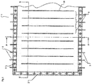
- FIG. 1 shows the electrolysis cell 1 in a plan view.
- bobendurdh Uniten 3 are provided at regular intervals.
- a plurality of inlets 5 are arranged.
- the entire electrolysis cell 1 is divided into compartments 8, wherein each compartment 8 is associated with an inlet 5 and a drain 7.
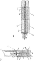
- the sectional view Fig. 2 shows the inlet region of the electrolysis cell 1 in a vertical sectional view along the line A.
- the cathode half-shell 9 has between the cathode 10 and the ion exchange membrane 11 has a cathode chamber 12.
- a filler 14 is inserted from a plastic, which is cut at an angle to the inlet 5, so that below the cell edge 6, a channel 15 is formed with a triangular cross-section.
- the closure of the cathode rear space 13 leads to a complete deflection of the fluid in the cells via the edge gap 16 and openings 17 in the cathode 10 in the region of the channel 15 in the cathode compartment 12.
- the contact strip 20 is further shown, via which adjacent electrolysis cells 1 in electrical contact with each other.
- the structure of the anode half-shell 18 and the components contained therein is substantially identical. Not provided are additional openings 17 in the anode 19 in the vicinity of the edge gap 16, since the volume flows are smaller than on the cathode side.
- Fig. 3 shows a sectional view taken along the line B of Fig.1 , Evident are the packing 14, which are introduced into the back spaces of the electrodes, each packing 14 fills exactly a compartment 8 and the compartments 8 are formed by the webs 21, which hold the electrodes and are connected to the rear wall of the respective cell half-shell.
- spacers 23 are arranged in the region of the webs, which fix the ion exchange membrane 11 locally.
Description
Die vorliegende Erfindung betrifft eine Elektrolysevorrichtung zur Wasserreinigung, umfassend eine Kathode, eine Anode und eine lonenaustauschmembran, die zwischen der Kathode und Anode angeordnet ist und mindestens umlaufend im Randbereich gehalten wird. Die Erfindung richtet sich auf eine Elektrolysevorrichtung zur Reinigung von sauren Wässern, die eine Kathode, eine Anode und eine Ionenaustauschmembran umfasst, wobei die Membran zwischen der Kathode und Anode angeordnet ist und mindestens umlaufend im Randbereich gehalten wird, wobei auf dem oberen und unteren Randbereich der Elektrolysevorrichtung eine Vielzahl von Zu- und Abläufen angeordnet sind, die mit dem Kathodenbeziehungsweise dem Anodenraum verbunden sind, so dass sich im Kathoden und dem Anodenraum eine Pfropfenströmung ausbildet, die im idealen Fall ein laminares Profil aufweist.The present invention relates to an electrolysis apparatus for water purification, comprising a cathode, an anode and an ion exchange membrane, which is arranged between the cathode and anode and is held at least peripherally in the edge region. The invention is directed to an electrolysis device for purifying acidic waters, comprising a cathode, an anode and an ion exchange membrane, wherein the membrane between the cathode and anode is arranged and is held at least circumferentially in the edge region, wherein on the upper and lower edge region of the Electrolysis apparatus a plurality of inlets and outlets are arranged, which are connected to the cathode or the anode chamber, so that forms a plug flow in the cathode and the anode space, which has a laminar profile in the ideal case.
Die Sanierung schwefelsaurer Wässer aus Tagebaurestseen wird aufgrund der großen Wassermengen zur Zeit vor allem durch die Flutung mit ggf. konditioniertem Fremdwasser durchgeführt. Dieses Verfahren ist jedoch unter anderem stark begrenzt durch das zur Verfügung stehende Wasserangebot, den Aufwand zur Überleitung und die abzupuffernde Basenkapazität. Eine Sanierung der Restlochgewässer durch Kalkung ist in den meisten Fällen wegen des hohen stöchiometrischen Überschusses an basischen Stoffen unwirtschaftlich.The remediation of sulfuric acid waters from opencast mining lakes is currently being carried out mainly by the flooding with possibly conditioned extraneous water due to the large amounts of water. However, this method is, among other things, severely limited by the available water supply, the cost of the transfer and the base capacity to be buffered. Remediation of the residual hole waters by liming is in most cases uneconomical because of the high stoichiometric excess of basic substances.
In der
- (1)
4H+ + 4e- -> 2H2
- (2)
4H2O + 4e- -> 2H2 + 4OH-
- (1)
4H + + 4e - -> 2H 2
- (2)
4H 2 O + 4e - -> 2H 2 + 4OH -
In gleicher Weise wirkt prinzipiell die simultan ablaufende elektrochemische Reduktion von im Wasser gelösten Sauerstoff zu Hydroxidionen neutralisierend.
- (3)
2H2O + O2+ 4e- -> 4OH-
- (3)
2H 2 O + O 2 + 4e - -> 4OH -
Die Reaktion (3) trägt jedoch nur geringfügig zur kathodischen Wasseraufbereitung bei. Durch den Einsatz einer Ionenaustauschmembran zwischen Anoden- und Kathodenraum der Elektrolysezelle wird zusätzlich erreicht, dass zur Anhebung des pH-Wertes, und der damit einher gehenden Hydrolyse und Fällung von Aluminium- und Schwermetallionen, auch der Salzgehalt der Wässer erheblich vermindert wird. Dabei wird eine Kopplung des kathodischen Wasseraufbereitungsprozesses mit einem anodischen Syntheseprozess vorgesehen. Bei Vorhandensein von Sulfationen können anodisch folgende Reaktionen ablaufen:
- (4)
2H2O -> 4H- + O2 + 4e-
- (5)
2SO4 2- -> S2O8 2- + 2e-
- (4)
2H 2 O -> 4H - + O 2 + 4e -
- (5)
2SO 4 2- > S 2 O 8 2- + 2e -
Bei einer Reaktion gemäß der Gleichung (4) werden die entstehenden Protonen durch die in den Anodenraum wandernden Sulfationen abgesättigt, wobei zunächst Schwefelsäure gebildet und aufkonzentriert wird. Im zweiten Fall werden Sulfationen zu Peroxodisulfat oxidiert und im Anodenraum angereichert. Durch nachfolgende Prozesse ist eine Gewinnung dieser Produkte möglich. In ähnlicher Weise kann der in der Kathodenreaktion gebildete Wasserstoff nachfolgend als Produkt verwertet werden.In a reaction according to equation (4), the resulting protons are saturated by the sulfate ions migrating into the anode space, wherein first sulfuric acid is formed and concentrated. In the second case sulfate ions are oxidized to peroxodisulfate and enriched in the anode compartment. Subsequent processes make it possible to obtain these products. Similarly, the hydrogen formed in the cathode reaction can subsequently be utilized as a product.
An diesen im Prinzip bekannten Verfahren und den bekannten Vorrichtungen ist nachteilig, dass bei den bekannten Elektrolysevorrichtungen sehr hohe Stromspannungen angelegt werden müssen, um Fluide zu reinigen, deren Ionenkonzentration im Vergleich zu klassischen Elektrolyseverfahren, wie bspw. der Chlor-Alkali-Elektrolyse, sehr gering sind und entsprechend schlecht leiten. Aus der
Aufgabe der Erfindung ist es somit, eine Vorrichtung zu offenbaren, die für Fluide mit geringen Ionenkonzentrationen geeignet ist und sich im bestimmungsgemäßen Betrieb durch einen geringen Energiebedarf auszeichnet.The object of the invention is thus to disclose a device which is suitable for fluids with low ion concentrations and is characterized in the normal operation by a low energy consumption.
Die Lösung dieser Aufgabe liefert eine Elektrolysevorrichtung zur Wasserreinigung mit den Merkmalen des Anspruchs 1. Die vorliegende Anmeldung offenbart eine Elektrolysevorrichtung zur Wasserreinigung, die eine Kathode, eine Anode und eine lonenaustauschmembran aufweist, wobei die Ionenaustauschmembran zwischen der Kathode und Anode angeordnet ist und mindestens umlaufend im Randbereich gehalten wird. Dabei sind auf dem oberen und unteren Randbereich der Elektrolysevorrichtung eine Vielzahl von Zu- und Abläufen angeordnet, die mit dem Kathoden- bzw. dem Anodenraum fluidisch verbunden sind.The object of the present invention is to provide an electrolysis device for water purification which has a cathode, an anode and an ion exchange membrane, the ion exchange membrane being arranged between the cathode and anode and at least circulating in the water Edge area is held. In this case, a plurality of inlets and outlets are arranged on the upper and lower edge region of the electrolysis device, which are fluidically connected to the cathode or the anode space.
Es wurde gefunden, dass sich ein weitgehend laminares Strömungsprofil mit relativ engem Verweilzeitspektrum, das durch eine Pfropfenströmung beschrieben werden kann, sich in der erfindungsgemäßen Vorrichtung ausbildet. Beim Einsatz dieser Vorrichtung konnten sehr gute Abbauergebnisse, bei gleichzeitig geringem Stromverbrauch beobachtet werden. Zum Aufbau einer stabilen laminar geschichteten Strömung und gleichzeitig geringem Stromverbrauch beträgt der Elektrodenabstand von der Ionentauschermembran maximal 5 mm und unterschreitet 1,5 mm nicht.It has been found that a largely laminar flow profile with a relatively narrow residence time spectrum, which can be described by a plug flow, is formed in the device according to the invention. When using this device very good degradation results could be observed with low power consumption. To build up a stable laminar layered flow and at the same time low power consumption, the electrode distance from the ion exchange membrane is a maximum of 5 mm and does not fall below 1.5 mm.
Eine vorteilhafte Ausführungsform besteht darin, dass die Elektrolysevorrichtung in der Bauwelse von Einzelzellen konstruiert Ist. Eine derartige Einzelzelle besteht im Wesentlichen aus zwei Halbschalen, wobei der äußerste Rand der Halbschalen als umlaufender Flansch ausgebildet ist, an den sich nach einer umlaufenden Kante ein Zellenrand anschließt, der die Zellenrückwand umrandet. Die Elektroden sind mittels Stegen von innen an der jeweiligen Zellenrückwand befestigt und den Stegen gegenüber, auf der der Membran zugewandten Elektrodenseite, sind Abstandselemente zur Fixierung der Membran und Kraftdurchleitung angeordnet. Dadurch wird die Elektrode sowie der Anoden- und Kathodenraum in mehrere parallele Kompartimente unterteilt.An advantageous embodiment is that the electrolysis device is constructed in the catfish of single cells. Such a single cell consists essentially of two half-shells, wherein the outermost edge of the half-shells is formed as a circumferential flange, which is followed by a peripheral edge of a cell edge which surrounds the cell rear wall. The electrodes are fixed by means of webs from the inside to the respective cell rear wall and the webs opposite, on the membrane side facing the electrode side, spacer elements for fixing the membrane and force transmission are arranged. As a result, the electrode and the anode and cathode compartments are subdivided into several parallel compartments.
Im bestimmungsgemäßen Betrieb werden eine Vielzahl derartiger Einzelzellen in einer Haltevorrichtung planparallel hintereinander aufgehängt, miteinander verspannt und nacheinander senkrecht zu den Membran bzw. Elektrodenflächen vom Strom durchflössen.In normal operation, a plurality of such individual cells are suspended in a holding device plane-parallel behind one another, clamped together and flowed through successively perpendicular to the membrane or electrode surfaces from the stream.
Vorteilhafter Weise sind die Zu- und Abläufe von der Membran aus gesehen hinter der Elektrode angeordnet und jedem Kompartiment ist mindestens ein Zulauf und ein Ablauf zugeordnet. Eine weitere Verbesserung besteht darin, dass der Raum zwischen Zellenrückwand und Elektrode, also der Elektrodenrückraum, über90 % mit einem inerten Material gefüllt ist, so dass das Wasser im bestimmungsgemäßen Betrieb bis auf geringe Randströmungen in dem Raum zwischen Elektrode und Membran geleitet wird. Idealerweise wird der Elektrodenrückraum vollständig geschlossen.Advantageously, the inflows and outflows from the membrane are arranged behind the electrode, and each compartment is assigned at least one inlet and one outlet. A further improvement consists in that the space between the cell rear wall and the electrode, that is to say the electrode rear space, is filled with an inert material by more than 90%, so that the water is conducted in normal operation to small edge flows in the space between electrode and membrane. Ideally, the back of the electrode is completely closed.
Zur verbesserten Strömungsführung für die Zu- und Ableitung von Fluiden ist das inerte Material im Bereich der Zu- und Abläufe so geformt oder weist eine entsprechende Aussparung auf, dass parallel zur oberen und unteren Zellenwand ein oder mehrere Kanäle ausgebildet sind. Das Fluid strömt dann durch den Spalt in den Kathoden- oder Anodenräum, welcher sich zwischen dem Rand der Jeweiligen Elektrode und dem Zellenrand ergibt. Idealerweise ist dieser Spalt zwischen oberer und unterer Kante der Elektroden und Zellenrand mindestens 0,5 mm und maximal 5 mm breit.For improved flow guidance for the supply and discharge of fluids, the inert material in the region of the inlets and outlets is shaped or has a corresponding recess in that one or more channels are formed parallel to the upper and lower cell wall. The fluid then flows through the gap into the cathode or anode space which results between the edge of the respective electrode and the cell edge. Ideally, this gap between upper and lower edge of the electrodes and cell edge is at least 0.5 mm and at most 5 mm wide.
Da der Volumenstrom auf in der Kathodenhalbschale sehr groß ist, weist die Kathode zusätzlich an der oberen und an der unteren Kante, Aussparungen, Bohrungen oder dergleichen auf. Das in den Kathodenrückraum einströmende Wasser kann somit in geeigneter Weise in den Kathodenraum geleitet werden, ohne dass der Druck in der Zuleitung stark erhöht werden muss.Since the volume flow in the cathode half-shell is very large, the cathode additionally has at the upper and at the lower edge, recesses, bores or the like. The water flowing into the cathode rear space can thus be passed in a suitable manner into the cathode space without the pressure in the supply line having to be greatly increased.
Idealerweise ist bei der erfindungsgemäßen Vorrichtung die Anode als Streckmetall und die Kathode als ebene Platte ausgebildet. Die den Elektrodenrückraum ausfüllenden Füllkörper, sind vorteilhafterweise an den senkrecht verlaufenden Kanten zur Entwässerung des Elektrodenrückraums und zur Vermeidung von Korrosion abgefasst.Ideally, in the device according to the invention, the anode is designed as expanded metal and the cathode as a flat plate. The filling bodies filling the back of the electrode are advantageously formed on the vertical edges for dewatering the back of the electrode and to prevent corrosion.
Nachfolgend werden in
Die gesamte Elektrolysezelle 1 ist in Kompartimente 8 aufgeteilt, wobei jedem Kompartiment 8 ein Zulauf 5 und ein Ablauf 7 zugeordnet ist. Die Schnittdarstellung
Der Aufbau der Anodenhalbschale 18 und der dort enthaltenen Komponenten ist im Wesentlichen identisch. Nicht vorgesehen sind zusätzliche Öffnungen 17 in der Anode 19 in der Nähe des Randspaltes 16, da die Volumenströme kleiner sind als auf der Kathodenseite.The structure of the anode half-
- 11
- Elektrolysezelleelectrolysis cell
- 22
- ZellenfranschZellenfransch
- 33
- SchraubendurchführungenScrew bushings
- 44
- Zellenrand (oberer)Cell border (upper)
- 55
- ZulaufIntake
- 66
- Zellenrand (unterer)Cell border (lower)
- 77
- Ablaufprocedure
- 88th
- Kompartimentcompartment
- 99
- KathodenhalbschaleCathode half-shell
- 1010
- Kathodecathode
- 1111
- lonenaustauschmembranion-exchange membrane
- 1212
- Kathodenraumcathode space
- 1313
- KathodenrückraumCathode back chamber
- 1414
- Füllkörperpacking
- 1515
- Kanalchannel
- 1616
- Randspaltmarginal gap
- 1717
- Öffnungenopenings
- 1818
- AnodenhalbschaleAnode half shell
- 1919
- Anodeanode
- 2020
- Kontaktleistecontact strip
- 2121
- Stegweb
- 2222
- Anodenraumanode chamber
- 2323
- Abstandshalterspacer
Claims (6)
- Electrolysis device for the purification of water, comprising a cathode, an anode and an ion exchange membrane, which is arranged between the cathode and the anode and is held at least circumferentially in the peripheral area,
characterized in that(a) the electrolysis device is structurally designed in the form of individual cells and is substantially formed by two half-shells,(i) wherein the outermost border of the half-shells is formed as a circumferential flange, which is adjoined after a circumferential edge by a cell border which borders the rear wall of the cell,(ii) wherein the electrodes are attached from the inside to the respective cell rear wall by means of webs and, opposite the webs, on the electrode side facing the membrane, spacing elements are arranged for fixing the membrane and conducting the power, whereby the electrode and the anode and cathode chambers that form between the respective electrode and the membrane are subdivided into a number of parallel compartments,(iii) wherein the space between the cell rear wall and the electrode is filled to over 90% with an inert material, so that, during operation as intended, the water is directed into the space between the electrode and the membrane apart from small peripheral flows, and(b) a multiplicity of feed inlets and discharge outlets are arranged on the upper and lower peripheral regions of the electrolysis device. - Electrolysis device for the purification of water according to Claim 1,
characterized in that
the feed inlets and discharge outlets are arranged behind the electrode, as seen from the membrane, and each compartment is assigned at least one feed inlet and one discharge outlet. - Electrolysis device for the purification of water according to Claim 2,
characterized in that
in the region of the feed inlets and discharge outlets, the inert material is shaped in such a way, or has such an aperture, that one or more channels are formed parallel to the cell wall. - Electrolysis device for the purification of water according to Claims 1 to 3,
characterized in that
the upper and lower edges of the electrodes are at a distance from the cell border of at least 0.5 mm and at most 5 mm. - Electrolysis device for the purification of water according to Claims 1 to 4,
characterized in that
the cathode comprises openings, apertures or the like at the upper edge and the lower edge that respectively lie opposite the feed inlets and discharge outlets. - Electrolysis device for the purification of water according to Claims 1 to 5,
characterized in that
the anode is formed as an expanded metal mesh and the cathode is formed as a planar sheet.
Priority Applications (1)
| Application Number | Priority Date | Filing Date | Title |
|---|---|---|---|
| PL07725261T PL2029492T3 (en) | 2006-06-16 | 2007-05-16 | Device for electrochemical water preparation |
Applications Claiming Priority (2)
| Application Number | Priority Date | Filing Date | Title |
|---|---|---|---|
| DE102006028168A DE102006028168A1 (en) | 2006-06-16 | 2006-06-16 | Apparatus for electrochemical water treatment |
| PCT/EP2007/004345 WO2007144055A1 (en) | 2006-06-16 | 2007-05-16 | Device for electrochemical water preparation |
Publications (2)
| Publication Number | Publication Date |
|---|---|
| EP2029492A1 EP2029492A1 (en) | 2009-03-04 |
| EP2029492B1 true EP2029492B1 (en) | 2017-10-18 |
Family
ID=38326275
Family Applications (1)
| Application Number | Title | Priority Date | Filing Date |
|---|---|---|---|
| EP07725261.7A Not-in-force EP2029492B1 (en) | 2006-06-16 | 2007-05-16 | Device for electrochemical water preparation |
Country Status (11)
| Country | Link |
|---|---|
| US (1) | US8444833B2 (en) |
| EP (1) | EP2029492B1 (en) |
| JP (1) | JP5069292B2 (en) |
| KR (1) | KR101398341B1 (en) |
| CN (1) | CN101472846B (en) |
| BR (1) | BRPI0713279B1 (en) |
| CA (1) | CA2655437C (en) |
| DE (1) | DE102006028168A1 (en) |
| PL (1) | PL2029492T3 (en) |
| RU (1) | RU2440302C2 (en) |
| WO (1) | WO2007144055A1 (en) |
Families Citing this family (9)
| Publication number | Priority date | Publication date | Assignee | Title |
|---|---|---|---|---|
| KR101300482B1 (en) * | 2010-03-31 | 2013-09-02 | 순천대학교 산학협력단 | Air Pollutants Removal Apparatus using Mediated Ions and Reductants, And Operation Method Thereof |
| MX2015003700A (en) * | 2012-09-21 | 2015-10-30 | Reoxcyn Discoveries Group Inc | Cell for electrolyzing a liquid. |
| DE102015118352A1 (en) | 2015-10-27 | 2017-04-27 | Thyssenkrupp Uhde Chlorine Engineers Gmbh | Electrolyzer for electrochemical water treatment |
| CN106145275A (en) * | 2016-06-30 | 2016-11-23 | 浙江科源环境科技有限公司 | A kind of closed piston flow electrocatalysis device and method of wastewater treatment |
| RU175909U1 (en) * | 2016-10-31 | 2017-12-22 | Алексей Сергеевич Горшков | Individually portable device for electrochemical treatment of drinking water |
| EP3357868A1 (en) * | 2017-02-07 | 2018-08-08 | Bwt Aktiengesellschaft | Water softening device and method to operate a water softening device |
| DE102017217361A1 (en) | 2017-09-29 | 2019-04-04 | Thyssenkrupp Uhde Chlorine Engineers Gmbh | electrolyzer |
| RU2769530C2 (en) * | 2020-03-03 | 2022-04-01 | Сергей Викторович Ивченко | Flow electrolytic cell and method of producing activated water therein |
| US11431012B1 (en) * | 2021-08-09 | 2022-08-30 | Verdagy, Inc. | Electrochemical cell with gap between electrode and membrane, and methods to use and manufacture thereof |
Family Cites Families (40)
| Publication number | Priority date | Publication date | Assignee | Title |
|---|---|---|---|---|
| US3976550A (en) * | 1971-09-22 | 1976-08-24 | Oronzio De Nora Implanti Elettrochimici S.P.A. | Horizontal, planar, bipolar diaphragm cells |
| US3823081A (en) * | 1972-12-18 | 1974-07-09 | Kettering Scient Res Inc | Acid mine water treatment process |
| US4149952A (en) * | 1975-04-15 | 1979-04-17 | Asahi Glass Co. Ltd. | Electrolytic cell |
| JPS51119681A (en) * | 1975-04-15 | 1976-10-20 | Asahi Glass Co Ltd | A cell frame for an electrolizer |
| US4065376A (en) * | 1976-05-04 | 1977-12-27 | Diamond Shamrock Corporation | Electrolytic cell |
| US4056458A (en) * | 1976-08-26 | 1977-11-01 | Diamond Shamrock Corporation | Monopolar membrane electrolytic cell |
| US4137145A (en) * | 1978-01-03 | 1979-01-30 | Hooker Chemicals & Plastics Corp. | Separating web for electrolytic apparatuses |
| US4210511A (en) * | 1979-03-08 | 1980-07-01 | Billings Energy Corporation | Electrolyzer apparatus and electrode structure therefor |
| US4233146A (en) * | 1979-03-09 | 1980-11-11 | Allied Chemical Corporation | Cell flow distributors |
| US4244802A (en) * | 1979-06-11 | 1981-01-13 | Diamond Shamrock Corporation | Monopolar membrane cell having metal laminate cell body |
| GB2058409A (en) | 1979-09-07 | 1981-04-08 | Nat Res Dev | Controlling ph or ion concentration of a stream |
| US4295953A (en) * | 1980-01-02 | 1981-10-20 | Chlorine Engineers Corp., Ltd. | Filter press type ion exchange membrane-method electrolysis cell |
| JPS5743992A (en) * | 1980-08-29 | 1982-03-12 | Asahi Glass Co Ltd | Electrolyzing method for alkali chloride |
| JPS57108278A (en) * | 1980-12-26 | 1982-07-06 | Asahi Glass Co Ltd | Double-electrode filter press type electrolytic cell |
| DE3108255C2 (en) * | 1981-03-05 | 1986-05-07 | Kernforschungsanlage Jülich GmbH, 5170 Jülich | Assembly unit for electrolysis cells for alkaline water electrolysis and process for producing the same |
| US4346150A (en) * | 1981-06-01 | 1982-08-24 | Exxon Research & Engineering Co. | Electrochemical construction |
| DE3373632D1 (en) * | 1982-05-27 | 1987-10-22 | Geesthacht Gkss Forschung | Membrane stack assembly |
| DE3420483A1 (en) * | 1984-06-01 | 1985-12-05 | Hoechst Ag, 6230 Frankfurt | BIPOLAR ELECTROLYSIS WITH GAS DIFFUSION CATHODE |
| US4588483A (en) * | 1984-07-02 | 1986-05-13 | Olin Corporation | High current density cell |
| DE3439265A1 (en) * | 1984-10-26 | 1986-05-07 | Hoechst Ag, 6230 Frankfurt | ELECTROLYSIS APPARATUS WITH HORIZONTALLY ARRANGED ELECTRODES |
| DE3501261A1 (en) * | 1985-01-16 | 1986-07-17 | Uhde Gmbh, 4600 Dortmund | ELECTROLYSIS |
| DE3614005A1 (en) | 1986-04-25 | 1987-10-29 | Westfael Elekt Werke | METHOD FOR DESCONDING SMOKE GAS |
| BE1004364A3 (en) * | 1989-08-11 | 1992-11-10 | Solvay | Chassis for electrolyser type filter press and electrolyser monopolar type of filter press. |
| JP3094735B2 (en) * | 1992-12-08 | 2000-10-03 | トーホーテック株式会社 | Electrolytic ionic water generator |
| JP3213213B2 (en) * | 1995-09-06 | 2001-10-02 | ホシザキ電機株式会社 | Electrolytic cell |
| DE19624023B9 (en) | 1996-06-17 | 2009-05-20 | Verein für Kernverfahrenstechnik und Analytik Rossendorf e.V. | Process for the remediation of acidic, iron-containing open cast mining water |
| DE19641125A1 (en) * | 1996-10-05 | 1998-04-16 | Krupp Uhde Gmbh | Electrolysis apparatus for the production of halogen gases |
| DE19740637A1 (en) | 1997-09-16 | 1999-04-01 | Abb Research Ltd | Flow regulator for varnish spray pistol |
| JP3145347B2 (en) * | 1997-10-22 | 2001-03-12 | 株式会社ケミコート | Method for producing electrolytic ionic water and generated water |
| US6294073B1 (en) | 1997-10-22 | 2001-09-25 | Chemicoat & Co., Ltd. | Manufacturing method and apparatus of alkaline ionized water |
| US6464945B1 (en) * | 1999-03-11 | 2002-10-15 | Delphi Technologies, Inc. | Non-thermal plasma exhaust NOx reactor |
| JP2000308887A (en) * | 1999-04-27 | 2000-11-07 | Matsushita Electric Ind Co Ltd | Water purifying device |
| WO2001083378A1 (en) * | 2000-04-27 | 2001-11-08 | Nippon Oil Corporation | Method and apparatus for clarification treatment of water |
| JP2004188398A (en) * | 2002-12-06 | 2004-07-08 | Chemicoat & Co Ltd | Flowing water type highly electrolyzed water producing apparatus |
| JP2004324190A (en) * | 2003-04-24 | 2004-11-18 | Shinko Plant Kensetsu Kk | Hand washing device using ozone water, and ozone water concentration maintaining device |
| US7309408B2 (en) * | 2003-06-11 | 2007-12-18 | Alfonso Gerardo Benavides | Industrial wastewater treatment and metals recovery apparatus |
| DE202004006303U1 (en) * | 2003-11-26 | 2004-11-04 | Altmeier, Patrik, Dr. | Electro-chemical assembly processes brine that is used in the preparation of drinking water has cells sub-divided by diaphragm partition |
| JP4394942B2 (en) * | 2003-12-22 | 2010-01-06 | 株式会社Ihiシバウラ | Electrolytic ozonizer |
| DE102004026447B4 (en) * | 2004-05-29 | 2009-09-10 | Verein für Kernverfahrenstechnik und Analytik Rossendorf e.V. | Process and apparatus for separating sulfate ions from waters and for introducing buffer capacity into waters |
| KR200397851Y1 (en) * | 2005-04-12 | 2005-10-10 | 김상수 | Electrolytic cell for sea water |
-
2006
- 2006-06-16 DE DE102006028168A patent/DE102006028168A1/en not_active Ceased
-
2007
- 2007-05-16 KR KR1020087030002A patent/KR101398341B1/en active IP Right Grant
- 2007-05-16 CA CA2655437A patent/CA2655437C/en not_active Expired - Fee Related
- 2007-05-16 JP JP2009514653A patent/JP5069292B2/en not_active Expired - Fee Related
- 2007-05-16 RU RU2009101163/05A patent/RU2440302C2/en active
- 2007-05-16 US US12/308,444 patent/US8444833B2/en active Active
- 2007-05-16 PL PL07725261T patent/PL2029492T3/en unknown
- 2007-05-16 BR BRPI0713279A patent/BRPI0713279B1/en not_active IP Right Cessation
- 2007-05-16 WO PCT/EP2007/004345 patent/WO2007144055A1/en active Application Filing
- 2007-05-16 CN CN200780022554XA patent/CN101472846B/en not_active Expired - Fee Related
- 2007-05-16 EP EP07725261.7A patent/EP2029492B1/en not_active Not-in-force
Non-Patent Citations (1)
| Title |
|---|
| None * |
Also Published As
| Publication number | Publication date |
|---|---|
| CA2655437C (en) | 2014-09-23 |
| CN101472846B (en) | 2012-08-22 |
| KR20090020599A (en) | 2009-02-26 |
| EP2029492A1 (en) | 2009-03-04 |
| US8444833B2 (en) | 2013-05-21 |
| DE102006028168A1 (en) | 2007-12-20 |
| CA2655437A1 (en) | 2007-12-21 |
| CN101472846A (en) | 2009-07-01 |
| BRPI0713279B1 (en) | 2018-09-04 |
| RU2009101163A (en) | 2010-07-27 |
| BRPI0713279A2 (en) | 2012-02-28 |
| JP5069292B2 (en) | 2012-11-07 |
| WO2007144055A1 (en) | 2007-12-21 |
| RU2440302C2 (en) | 2012-01-20 |
| KR101398341B1 (en) | 2014-05-22 |
| PL2029492T3 (en) | 2018-04-30 |
| US20100294653A1 (en) | 2010-11-25 |
| JP2009539588A (en) | 2009-11-19 |
Similar Documents
| Publication | Publication Date | Title |
|---|---|---|
| EP2029492B1 (en) | Device for electrochemical water preparation | |
| AT401739B (en) | DEVICE FOR TREATING METAL CONTAINING LIQUIDS BY ION EXCHANGE AND SIMULTANEOUSLY OR PERIODICALLY REGENERATING THE ION EXCHANGE RESIN BY ELECTRODIALYSIS | |
| DE4444114C2 (en) | Electrochemical half cell with pressure compensation | |
| DE60017104T2 (en) | WATER TREATMENT PROCESS | |
| DE3014885A1 (en) | ELECTRODE ARRANGEMENT | |
| DE2435185A1 (en) | BIPOLAR ELECTROLYTE CELL | |
| EP2697410B1 (en) | Alternative installation of a gas diffusion electrode in an electrochemical cell having percolator technology | |
| DE2646463A1 (en) | PLATE ELECTRODE FOR AN ELECTROLYSIS CELL | |
| DE2856882A1 (en) | ELECTROLYZING DEVICE AND METHOD FOR PRODUCING CHLORINE BY ELECTROLYZING | |
| WO2015128076A1 (en) | Method for electrochemically producing electrolyzed water | |
| DE4003516C2 (en) | Electrode element for electrolytic purposes and its use | |
| DE1467067A1 (en) | Electrolytic cell | |
| WO2009030203A2 (en) | Electrolysis cell with a high electric current capacity for producing an ozone-oxygen mixture | |
| EP0337050A1 (en) | Process and apparatus for the partial or total demineralisation of water | |
| DE2923818C2 (en) | ||
| DE2538000B2 (en) | Bipolar electrode construction for a membrane-free electrolysis cell | |
| DE102004026447A1 (en) | Process and apparatus for separating sulfate ions from waters and for introducing buffer capacity into waters | |
| EP0383927A1 (en) | Method and electrolyzer for softening water | |
| DD270934A5 (en) | ELECTROLYTIC CELL | |
| EP2141264B1 (en) | Apparatus for producing an oxygen/hydrogen mixture | |
| DE4224492C1 (en) | Apparatus for the electrolytic treatment of liquids with an anode and a cathode chamber and their use | |
| WO2017072091A1 (en) | Electrolyzer for electrochemical water treatment | |
| DE2933652C2 (en) | ||
| DE4312600A1 (en) | Small desalination plant based on ion exchangers with electrolytically producible regeneration agents and process for their operation | |
| DE3046294C2 (en) |
Legal Events
| Date | Code | Title | Description |
|---|---|---|---|
| PUAI | Public reference made under article 153(3) epc to a published international application that has entered the european phase |
Free format text: ORIGINAL CODE: 0009012 |
|
| 17P | Request for examination filed |
Effective date: 20081119 |
|
| AK | Designated contracting states |
Kind code of ref document: A1 Designated state(s): AT BE BG CH CY CZ DE DK EE ES FI FR GB GR HU IE IS IT LI LT LU LV MC MT NL PL PT RO SE SI SK TR |
|
| AX | Request for extension of the european patent |
Extension state: AL BA HR MK RS |
|
| 17Q | First examination report despatched |
Effective date: 20090309 |
|
| RIN1 | Information on inventor provided before grant (corrected) |
Inventor name: STOLP, WOLFRAM Inventor name: KIEFER, RANDOLF Inventor name: BAEUMER, ULF-STEFFEN Inventor name: DULLE, KARL-HEINZ Inventor name: WOLTERING, PETER Inventor name: OELMANN, STEFAN |
|
| RAP1 | Party data changed (applicant data changed or rights of an application transferred) |
Owner name: THYSSENKRUPP UHDE GMBH |
|
| DAX | Request for extension of the european patent (deleted) | ||
| RAP1 | Party data changed (applicant data changed or rights of an application transferred) |
Owner name: THYSSENKRUPP INDUSTRIAL SOLUTIONS AG |
|
| RIC1 | Information provided on ipc code assigned before grant |
Ipc: C02F 103/10 20060101ALN20170110BHEP Ipc: C02F 1/461 20060101AFI20170110BHEP |
|
| GRAP | Despatch of communication of intention to grant a patent |
Free format text: ORIGINAL CODE: EPIDOSNIGR1 |
|
| INTG | Intention to grant announced |
Effective date: 20170222 |
|
| GRAS | Grant fee paid |
Free format text: ORIGINAL CODE: EPIDOSNIGR3 |
|
| GRAJ | Information related to disapproval of communication of intention to grant by the applicant or resumption of examination proceedings by the epo deleted |
Free format text: ORIGINAL CODE: EPIDOSDIGR1 |
|
| GRAL | Information related to payment of fee for publishing/printing deleted |
Free format text: ORIGINAL CODE: EPIDOSDIGR3 |
|
| INTC | Intention to grant announced (deleted) | ||
| RIC1 | Information provided on ipc code assigned before grant |
Ipc: C02F 103/10 20060101ALN20170704BHEP Ipc: C02F 1/461 20060101AFI20170704BHEP |
|
| GRAR | Information related to intention to grant a patent recorded |
Free format text: ORIGINAL CODE: EPIDOSNIGR71 |
|
| GRAA | (expected) grant |
Free format text: ORIGINAL CODE: 0009210 |
|
| INTG | Intention to grant announced |
Effective date: 20170907 |
|
| RAP1 | Party data changed (applicant data changed or rights of an application transferred) |
Owner name: THYSSENKRUPP UHDE CHLORINE ENGINEERS GMBH |
|
| AK | Designated contracting states |
Kind code of ref document: B1 Designated state(s): AT BE BG CH CY CZ DE DK EE ES FI FR GB GR HU IE IS IT LI LT LU LV MC MT NL PL PT RO SE SI SK TR |
|
| REG | Reference to a national code |
Ref country code: GB Ref legal event code: FG4D Free format text: NOT ENGLISH |
|
| REG | Reference to a national code |
Ref country code: CH Ref legal event code: EP |
|
| REG | Reference to a national code |
Ref country code: AT Ref legal event code: REF Ref document number: 937772 Country of ref document: AT Kind code of ref document: T Effective date: 20171115 Ref country code: IE Ref legal event code: FG4D Free format text: LANGUAGE OF EP DOCUMENT: GERMAN |
|
| REG | Reference to a national code |
Ref country code: DE Ref legal event code: R096 Ref document number: 502007015916 Country of ref document: DE |
|
| REG | Reference to a national code |
Ref country code: NL Ref legal event code: MP Effective date: 20171018 |
|
| REG | Reference to a national code |
Ref country code: LT Ref legal event code: MG4D |
|
| PG25 | Lapsed in a contracting state [announced via postgrant information from national office to epo] |
Ref country code: NL Free format text: LAPSE BECAUSE OF FAILURE TO SUBMIT A TRANSLATION OF THE DESCRIPTION OR TO PAY THE FEE WITHIN THE PRESCRIBED TIME-LIMIT Effective date: 20171018 |
|
| PG25 | Lapsed in a contracting state [announced via postgrant information from national office to epo] |
Ref country code: LT Free format text: LAPSE BECAUSE OF FAILURE TO SUBMIT A TRANSLATION OF THE DESCRIPTION OR TO PAY THE FEE WITHIN THE PRESCRIBED TIME-LIMIT Effective date: 20171018 Ref country code: FI Free format text: LAPSE BECAUSE OF FAILURE TO SUBMIT A TRANSLATION OF THE DESCRIPTION OR TO PAY THE FEE WITHIN THE PRESCRIBED TIME-LIMIT Effective date: 20171018 Ref country code: ES Free format text: LAPSE BECAUSE OF FAILURE TO SUBMIT A TRANSLATION OF THE DESCRIPTION OR TO PAY THE FEE WITHIN THE PRESCRIBED TIME-LIMIT Effective date: 20171018 Ref country code: SE Free format text: LAPSE BECAUSE OF FAILURE TO SUBMIT A TRANSLATION OF THE DESCRIPTION OR TO PAY THE FEE WITHIN THE PRESCRIBED TIME-LIMIT Effective date: 20171018 |
|
| PG25 | Lapsed in a contracting state [announced via postgrant information from national office to epo] |
Ref country code: LV Free format text: LAPSE BECAUSE OF FAILURE TO SUBMIT A TRANSLATION OF THE DESCRIPTION OR TO PAY THE FEE WITHIN THE PRESCRIBED TIME-LIMIT Effective date: 20171018 Ref country code: BG Free format text: LAPSE BECAUSE OF FAILURE TO SUBMIT A TRANSLATION OF THE DESCRIPTION OR TO PAY THE FEE WITHIN THE PRESCRIBED TIME-LIMIT Effective date: 20180118 Ref country code: GR Free format text: LAPSE BECAUSE OF FAILURE TO SUBMIT A TRANSLATION OF THE DESCRIPTION OR TO PAY THE FEE WITHIN THE PRESCRIBED TIME-LIMIT Effective date: 20180119 Ref country code: IS Free format text: LAPSE BECAUSE OF FAILURE TO SUBMIT A TRANSLATION OF THE DESCRIPTION OR TO PAY THE FEE WITHIN THE PRESCRIBED TIME-LIMIT Effective date: 20180218 |
|
| REG | Reference to a national code |
Ref country code: DE Ref legal event code: R097 Ref document number: 502007015916 Country of ref document: DE |
|
| PG25 | Lapsed in a contracting state [announced via postgrant information from national office to epo] |
Ref country code: EE Free format text: LAPSE BECAUSE OF FAILURE TO SUBMIT A TRANSLATION OF THE DESCRIPTION OR TO PAY THE FEE WITHIN THE PRESCRIBED TIME-LIMIT Effective date: 20171018 Ref country code: SK Free format text: LAPSE BECAUSE OF FAILURE TO SUBMIT A TRANSLATION OF THE DESCRIPTION OR TO PAY THE FEE WITHIN THE PRESCRIBED TIME-LIMIT Effective date: 20171018 Ref country code: DK Free format text: LAPSE BECAUSE OF FAILURE TO SUBMIT A TRANSLATION OF THE DESCRIPTION OR TO PAY THE FEE WITHIN THE PRESCRIBED TIME-LIMIT Effective date: 20171018 |
|
| PLBE | No opposition filed within time limit |
Free format text: ORIGINAL CODE: 0009261 |
|
| STAA | Information on the status of an ep patent application or granted ep patent |
Free format text: STATUS: NO OPPOSITION FILED WITHIN TIME LIMIT |
|
| PG25 | Lapsed in a contracting state [announced via postgrant information from national office to epo] |
Ref country code: RO Free format text: LAPSE BECAUSE OF FAILURE TO SUBMIT A TRANSLATION OF THE DESCRIPTION OR TO PAY THE FEE WITHIN THE PRESCRIBED TIME-LIMIT Effective date: 20171018 Ref country code: IT Free format text: LAPSE BECAUSE OF FAILURE TO SUBMIT A TRANSLATION OF THE DESCRIPTION OR TO PAY THE FEE WITHIN THE PRESCRIBED TIME-LIMIT Effective date: 20171018 |
|
| 26N | No opposition filed |
Effective date: 20180719 |
|
| PG25 | Lapsed in a contracting state [announced via postgrant information from national office to epo] |
Ref country code: MT Free format text: LAPSE BECAUSE OF FAILURE TO SUBMIT A TRANSLATION OF THE DESCRIPTION OR TO PAY THE FEE WITHIN THE PRESCRIBED TIME-LIMIT Effective date: 20171018 |
|
| PG25 | Lapsed in a contracting state [announced via postgrant information from national office to epo] |
Ref country code: SI Free format text: LAPSE BECAUSE OF FAILURE TO SUBMIT A TRANSLATION OF THE DESCRIPTION OR TO PAY THE FEE WITHIN THE PRESCRIBED TIME-LIMIT Effective date: 20171018 |
|
| REG | Reference to a national code |
Ref country code: CH Ref legal event code: PL |
|
| REG | Reference to a national code |
Ref country code: BE Ref legal event code: MM Effective date: 20180531 |
|
| PG25 | Lapsed in a contracting state [announced via postgrant information from national office to epo] |
Ref country code: MC Free format text: LAPSE BECAUSE OF FAILURE TO SUBMIT A TRANSLATION OF THE DESCRIPTION OR TO PAY THE FEE WITHIN THE PRESCRIBED TIME-LIMIT Effective date: 20171018 |
|
| REG | Reference to a national code |
Ref country code: IE Ref legal event code: MM4A |
|
| PG25 | Lapsed in a contracting state [announced via postgrant information from national office to epo] |
Ref country code: LI Free format text: LAPSE BECAUSE OF NON-PAYMENT OF DUE FEES Effective date: 20180531 Ref country code: CH Free format text: LAPSE BECAUSE OF NON-PAYMENT OF DUE FEES Effective date: 20180531 |
|
| PG25 | Lapsed in a contracting state [announced via postgrant information from national office to epo] |
Ref country code: LU Free format text: LAPSE BECAUSE OF NON-PAYMENT OF DUE FEES Effective date: 20180516 |
|
| PG25 | Lapsed in a contracting state [announced via postgrant information from national office to epo] |
Ref country code: IE Free format text: LAPSE BECAUSE OF NON-PAYMENT OF DUE FEES Effective date: 20180516 Ref country code: FR Free format text: LAPSE BECAUSE OF NON-PAYMENT OF DUE FEES Effective date: 20180531 |
|
| PG25 | Lapsed in a contracting state [announced via postgrant information from national office to epo] |
Ref country code: BE Free format text: LAPSE BECAUSE OF NON-PAYMENT OF DUE FEES Effective date: 20180531 |
|
| REG | Reference to a national code |
Ref country code: AT Ref legal event code: MM01 Ref document number: 937772 Country of ref document: AT Kind code of ref document: T Effective date: 20180516 |
|
| PG25 | Lapsed in a contracting state [announced via postgrant information from national office to epo] |
Ref country code: AT Free format text: LAPSE BECAUSE OF NON-PAYMENT OF DUE FEES Effective date: 20180516 |
|
| PG25 | Lapsed in a contracting state [announced via postgrant information from national office to epo] |
Ref country code: TR Free format text: LAPSE BECAUSE OF FAILURE TO SUBMIT A TRANSLATION OF THE DESCRIPTION OR TO PAY THE FEE WITHIN THE PRESCRIBED TIME-LIMIT Effective date: 20171018 |
|
| PG25 | Lapsed in a contracting state [announced via postgrant information from national office to epo] |
Ref country code: PT Free format text: LAPSE BECAUSE OF FAILURE TO SUBMIT A TRANSLATION OF THE DESCRIPTION OR TO PAY THE FEE WITHIN THE PRESCRIBED TIME-LIMIT Effective date: 20171018 Ref country code: HU Free format text: LAPSE BECAUSE OF FAILURE TO SUBMIT A TRANSLATION OF THE DESCRIPTION OR TO PAY THE FEE WITHIN THE PRESCRIBED TIME-LIMIT; INVALID AB INITIO Effective date: 20070516 |
|
| PG25 | Lapsed in a contracting state [announced via postgrant information from national office to epo] |
Ref country code: CY Free format text: LAPSE BECAUSE OF FAILURE TO SUBMIT A TRANSLATION OF THE DESCRIPTION OR TO PAY THE FEE WITHIN THE PRESCRIBED TIME-LIMIT Effective date: 20171018 |
|
| PGFP | Annual fee paid to national office [announced via postgrant information from national office to epo] |
Ref country code: DE Payment date: 20200520 Year of fee payment: 14 Ref country code: CZ Payment date: 20200514 Year of fee payment: 14 |
|
| PGFP | Annual fee paid to national office [announced via postgrant information from national office to epo] |
Ref country code: GB Payment date: 20200527 Year of fee payment: 14 Ref country code: PL Payment date: 20200511 Year of fee payment: 14 |
|
| REG | Reference to a national code |
Ref country code: DE Ref legal event code: R119 Ref document number: 502007015916 Country of ref document: DE |
|
| GBPC | Gb: european patent ceased through non-payment of renewal fee |
Effective date: 20210516 |
|
| PG25 | Lapsed in a contracting state [announced via postgrant information from national office to epo] |
Ref country code: CZ Free format text: LAPSE BECAUSE OF NON-PAYMENT OF DUE FEES Effective date: 20210516 |
|
| PG25 | Lapsed in a contracting state [announced via postgrant information from national office to epo] |
Ref country code: GB Free format text: LAPSE BECAUSE OF NON-PAYMENT OF DUE FEES Effective date: 20210516 Ref country code: DE Free format text: LAPSE BECAUSE OF NON-PAYMENT OF DUE FEES Effective date: 20211201 |
|
| PG25 | Lapsed in a contracting state [announced via postgrant information from national office to epo] |
Ref country code: PL Free format text: LAPSE BECAUSE OF NON-PAYMENT OF DUE FEES Effective date: 20210516 |