EP2029423B1 - Ausgleich für hebebewegung - Google Patents
Ausgleich für hebebewegung Download PDFInfo
- Publication number
- EP2029423B1 EP2029423B1 EP06757801A EP06757801A EP2029423B1 EP 2029423 B1 EP2029423 B1 EP 2029423B1 EP 06757801 A EP06757801 A EP 06757801A EP 06757801 A EP06757801 A EP 06757801A EP 2029423 B1 EP2029423 B1 EP 2029423B1
- Authority
- EP
- European Patent Office
- Prior art keywords
- piston
- cylinder
- compensator
- heave
- seal
- Prior art date
- Legal status (The legal status is an assumption and is not a legal conclusion. Google has not performed a legal analysis and makes no representation as to the accuracy of the status listed.)
- Active
Links
Images


Classifications
-
- E—FIXED CONSTRUCTIONS
- E21—EARTH DRILLING; MINING
- E21B—EARTH DRILLING, e.g. DEEP DRILLING; OBTAINING OIL, GAS, WATER, SOLUBLE OR MELTABLE MATERIALS OR A SLURRY OF MINERALS FROM WELLS
- E21B19/00—Handling rods, casings, tubes or the like outside the borehole, e.g. in the derrick; Apparatus for feeding the rods or cables
- E21B19/08—Apparatus for feeding the rods or cables; Apparatus for increasing or decreasing the pressure on the drilling tool; Apparatus for counterbalancing the weight of the rods
- E21B19/09—Apparatus for feeding the rods or cables; Apparatus for increasing or decreasing the pressure on the drilling tool; Apparatus for counterbalancing the weight of the rods specially adapted for drilling underwater formations from a floating support using heave compensators supporting the drill string
-
- B—PERFORMING OPERATIONS; TRANSPORTING
- B63—SHIPS OR OTHER WATERBORNE VESSELS; RELATED EQUIPMENT
- B63B—SHIPS OR OTHER WATERBORNE VESSELS; EQUIPMENT FOR SHIPPING
- B63B17/00—Vessels parts, details, or accessories, not otherwise provided for
-
- B—PERFORMING OPERATIONS; TRANSPORTING
- B63—SHIPS OR OTHER WATERBORNE VESSELS; RELATED EQUIPMENT
- B63B—SHIPS OR OTHER WATERBORNE VESSELS; EQUIPMENT FOR SHIPPING
- B63B27/00—Arrangement of ship-based loading or unloading equipment for cargo or passengers
- B63B27/30—Arrangement of ship-based loading or unloading equipment for transfer at sea between ships or between ships and off-shore structures
-
- B—PERFORMING OPERATIONS; TRANSPORTING
- B66—HOISTING; LIFTING; HAULING
- B66D—CAPSTANS; WINCHES; TACKLES, e.g. PULLEY BLOCKS; HOISTS
- B66D1/00—Rope, cable, or chain winding mechanisms; Capstans
- B66D1/28—Other constructional details
- B66D1/40—Control devices
- B66D1/48—Control devices automatic
- B66D1/52—Control devices automatic for varying rope or cable tension, e.g. when recovering craft from water
-
- E—FIXED CONSTRUCTIONS
- E21—EARTH DRILLING; MINING
- E21B—EARTH DRILLING, e.g. DEEP DRILLING; OBTAINING OIL, GAS, WATER, SOLUBLE OR MELTABLE MATERIALS OR A SLURRY OF MINERALS FROM WELLS
- E21B19/00—Handling rods, casings, tubes or the like outside the borehole, e.g. in the derrick; Apparatus for feeding the rods or cables
- E21B19/002—Handling rods, casings, tubes or the like outside the borehole, e.g. in the derrick; Apparatus for feeding the rods or cables specially adapted for underwater drilling
- E21B19/004—Handling rods, casings, tubes or the like outside the borehole, e.g. in the derrick; Apparatus for feeding the rods or cables specially adapted for underwater drilling supporting a riser from a drilling or production platform
- E21B19/006—Handling rods, casings, tubes or the like outside the borehole, e.g. in the derrick; Apparatus for feeding the rods or cables specially adapted for underwater drilling supporting a riser from a drilling or production platform including heave compensators
-
- B—PERFORMING OPERATIONS; TRANSPORTING
- B63—SHIPS OR OTHER WATERBORNE VESSELS; RELATED EQUIPMENT
- B63B—SHIPS OR OTHER WATERBORNE VESSELS; EQUIPMENT FOR SHIPPING
- B63B17/00—Vessels parts, details, or accessories, not otherwise provided for
- B63B2017/0072—Seaway compensators
Definitions
- the present invention relates to the field of heave motion compensation.
- the invention relates to heave motion compensators, which can be included in a heave compensation system.
- Heave motion compensation is used in many activities wherein the heave motion of the vessel - mainly induced by waves - is likely to impair said activities.
- the heave of the rig is compensated for in order to obtain a reduced variation of the weight on drill bit (the downward force on the drill bit).
- Heave compensation systems often are employed in vessel-mounted load handling systems, such as cable-suspended load handling systems (e.g. in cranes).
- cable-suspended load handling system a load is generally suspended from a cable and commonly a winch is provided to pay out or take up the cable.
- Such cable-suspended load handling systems are for instance employed to lower a load into the water (e.g. diving equipment), retrieving a load from the water (e.g. in salvage operations), placement of a load on the seabed (e.g. a template) or onto a subsea installation (BOP, wellhead equipment), or placement/lowering a load into a wellbore (well intervention equipment, logging tools, etc).
- heave compensation is, for example, employed in load handling systems on vessels used for construction and/or demolition of offshore structures (placement of superstructure on fixed rig).
- load handling systems with heave compensation are subsea pipelaying systems, and systems for coring or scientific subsea operations.
- each compensator is embodied as a piston and cylinder assembly having a variable volume hydraulic chamber in said cylinder.
- the variable volume hydraulic chamber is connected to a hydraulic chamber of an accumulator, said interconnected chambers being filled with hydraulic fluid.
- the accumulator has a freely slideable separating piston positioned between said hydraulic chamber and a gas chamber which is in turn connected to a bank of pressurised gas reservoirs.
- the pressure of the gas can be controlled, e.g. set at a desired level, by a gas pressure controller and in said manner the pressure within the variable volume hydraulic chamber of the compensators can be controlled.
- the heave motion compensation is included in a cable-suspended load handling system, and the piston of the compensators each support a movable or "flying" sheave guiding the cable in such a manner that heave motion of the vessel then causes the piston to oscillate within the cylinder of the compensator.
- the path of the cable from which a load is suspended is lengthened and shortened thus cancelling at least a part of the heave motion.
- a load handling system used in the offshore industry is the nodding-boom system, wherein a cable sheave is mounted on a boom, which boom is pivoted on a base. The boom is arranged to move up and down along with the heaving of the vessel. A compensator is mounted between the base and the boom in order to maintain a substantially constant cable tension.
- heave compensation is (also) obtained with an active heave compensation system, wherein the oscillations of the piston relative to the cylinder of the active compensator are governed by a unit supplying pressurised fluid (gas or hydraulic liquid) in a controlled manner to one or more variable volume chambers within the compensator based upon one or more input signals obtained by one or more suitable sensors (for example vertical vessel motion sensor (e.g. acceleration sensor), (cable) force sensor, compensator piston position sensor, etc).
- suitable sensors for example vertical vessel motion sensor (e.g. acceleration sensor), (cable) force sensor, compensator piston position sensor, etc).
- the present invention provides a heave motion compensator comprising a cylinder and a piston delimiting a variable volume fluid chamber in said cylinder, wherein said piston can oscillate within said cylinder, said piston being provided with a seal frictionally engaging said cylinder.
- the compensator is characterised in that said compensator further includes a motor that causes said seal to revolve relative to said cylinder.
- the present invention envisages to revolve or rotate the seal with respect to the cylinder during operation of the compensator.
- the invention achieves that the "transition" explained above does not occur as the friction already is within the dynamic regime. Also the frictional force is mainly in tangential direction, thus having limited effect on longitudinal motion of the piston with respect to the cylinder.
- the motor employed for establishing the revolving motion can be of any suitable design, e.g. including an electric motor, a hydraulic motor, a magnetic motor, etc.
- a suitable transmission assembly can be provided with the motor to drive the revolving part of the compensator.
- the revolving motion may include an oscillating revolving motion, but a continuous revolving motion is preferred for constructional reasons.
- the inventive concept is advantageous for passive heave compensators.
- the behaviour and efficiency thereof in relative calm wave conditions is significantly improved over prior art passive heave compensators.
- the inventive concept can equally be applied to active heave compensators in order to improve the behaviour thereof. In particular it will allow a more accurate compensation of the heave motions.
- the present invention can also be described as providing a heave motion compensator comprising a ram having a cylinder and a piston - piston rod assembly which is extendable and retractable relative to said cylinder, said piston - piston rod assembly frictionally engaging said cylinder, characterised in that said compensator further includes a motor adapted to cause at least said piston, preferably said piston - piston rod assembly, to rotate relative to said cylinder.
- the present invention can also be described as providing a heave motion compensator comprising a piston and cylinder assembly, wherein a variable volume fluid chamber is delimited by said piston in said cylinder, said variable volume chamber being connected to an accumulator, said piston frictionally engaging said cylinder, characterised in that said compensator further includes a drive assembly adapted to provide a revolving motion of said piston relative to said cylinder when said compensator is in use.
- the motor is arranged to revolve or rotate the piston within the cylinder during operation of the heave compensator, and the seal is mounted on said piston so as to rotate along with said piston.
- the motor is arranged to rotate the cylinder, and the piston is adapted to be mounted non-rotatable.
- a fluid conduit extends through the piston, which is connected to a pressurised fluid assembly external of said compensator, e.g. at a remote location.
- the seal is carried by a seal carrier which is mounted rotatable on said piston, and the said motor is arranged and adapted to drive said seal carrier so as to rotate it about the piston.
- the cylinder wherein the piston oscillates is an inner cylinder which is rotatably mounted within an outer cylinder, and wherein said outer cylinder is adapted to be mounted non-rotatable.
- the present invention also relates to a heave compensation system including a compensator as disclosed herein.
- a heave compensation system may include a cable from which a load (drill string or other drilling tubular, object, etc) is suspended.
- the heave compensator may engage on a sheave (or sheave assembly) guiding said cable in order to vary the path of the cable in order to obtain heave compensation.
- the compensator is placed directly between a part of the vessel subjected to heave and the load itself, for example between a travelling block in a drilling derrick, mast or other drilling structure on the one hand and the top drive unit or other suspension unit from which a drill string is suspended on the other hand.
- the present invention also relates to a vessel including a heave compensation system as disclosed herein.
- the present invention also relates to a vessel load handling system including a heave compensation system as disclosed herein.
- the present invention also relates to a floating rig drilling system including a heave compensation system as disclosed herein.
- the heave compensation system can be arranged between a heaving drilling structure on the vessel on the one hand and the drill string (or top drive supporting the drill string) on the other hand.
- the heave compensator could also be arranged within the drill string, e.g. at the upper end thereof.
- the present invention also relates to a floating rig drill string compensator adapted for placement between a drill string or other drilling tubular and a drill string hoisting device, for instance between a top drive that allows to support and rotate the drill string and a hoisting device supporting said top drive.
- the present invention also relates to a wireline logging system including a wireline cable, an associated wireline winch, and one or more instruments integrated into or fastened onto the wireline.
- the wireline with instruments is to be conveyed into a wellbore, said system further including a heave compensation system as disclosed herein.
- Wireline logging in general is the process by which oil or gas wells are surveyed to determine their geological, petrophysical or geophysical properties using electronic measuring instruments conveyed into the wellbore by means of a (armoured steel) cable, known as a wireline cable.
- the present invention also relates to a floating drilling vessel including a heave compensated drill floor, wherein the drill floor is mobile relative to the vessel to compensate for heave motion of the vessel, wherein a heave compensation system as disclosed herein is arranged between the vessel and the drill floor.
- the present invention also relates to a method for heave motion compensation, in particular heave motion compensated load handling on a vessel, wherein use is made of a heave motion compensator as disclosed herein, and wherein said seal is made to revolve relative to the cylinder of the heave compensator such that said friction between the seal and the cylinder is in the dynamic friction regime.
- An alternative approach to obtain improved heave motion compensator behaviour, in particular to overcome the stick-slip of prior art compensators, is to provide design the piston seal as a hydrostatic bearing, wherein a narrow gap is maintained between the piston seal and the cylinder and wherein a pressurised fluid is supplied through the piston to the gap so as to create a hydrostatic bearing.
- the piston may then be provided with one or more annular pockets, recessed with respect to the outer perimeter of the piston, and one or more fluid channels within the piston (possibly extending through the piston rod) connected to a source of pressurised fluid so that a continuous flow of fluid can be provided to maintain the spacing between the piston and the cylinder.
- a further hydrostatic bearing is provided between the piston rod and an end cover on the cylinder.
- hydrostatic bearing design in a compensator does not require the revolving motion discussed herein.
- a drawback of the hydrostatic bearing design resides in the need to compensate flow the loss of pressurised fluid in the bearing.
- a bank of one or more gas, preferably air, reservoirs and a compressor will be provided to feed the bearing.
- FIG. 1 shows a vessel 1, here for illustrative purposes an offshore drilling or well intervention vessel, having a drilling structure 2 (also referred as mast 2) thereon from which a drill string 3 or other drilling tubular (e.g. a riser) is suspended into the sea.
- a drilling structure 2 also referred as mast 2
- the vessel 1 is provided with a moonpool 4 and the drilling structure is embodied as a mast which is arranged adjacent said moonpool 4.
- the vessel is equipped with a hoisting device.
- a winch 6 is provided for paying out and taking up a cable 7.
- This cable 7 is guided over sheave assemblies 8,8a,8b, 9 in the structure 2 and a sheave assembly 10 on a travelling block 11.
- the travelling block 11 moveable up and down with respect to the structure 2, here guided along on or more vertical guide rails 12 mounted on the mast 2.
- a top drive unit 20 is provided, which can support the drill string suspended therefrom as well as impart rotary motion to the drill string in order to rotate the drill bit at the lower end of the drill string (not shown).
- top drive unit 20 is also guided vertically with respect to the structure 2, mainly in order to counter the torque exerted by the top drive unit.
- the top drive unit 20 is received in a trolley 21 which is guided along one or more vertical guide rails 12 on the mast 2.
- the top drive unit 20 may include a hydraulic motor to impart the torque to the drill string and a drill string clamp device to clamp and support the suspended drill string.
- the compensator 30 is a passive heave compensator.
- the compensator 30 allows the travelling block to move up and down as a result a waves (possibly including roll and/or pitch of the vessel) whereas the drill string 3 should remain unaffected by said heave motion. This in order to obtain a controlled weight on drill bit with a variation which is as low as possible.
- FIG 1 which merely is an example, also a further heave compensator 22 is shown, carrying flying sheave assembly 9. It is noted that in this figure 1 said compensator 22 is provided when the hoisting device is used for other purposes than drilling, e.g. when the device is used to raise or lower loads through the moonpool other than the drill string or the like. It will be appreciated that said heave compensator can be an active heave compensator.
- a heave compensation system including a heave motion compensator 40.
- the compensator 40 includes a cylinder 41 having end covers 42, 43.
- a piston 44 arranged on a piston rod 45 is placed within the cylinder 41 and can oscillate in longitudinal direction within said cylinder 41.
- the piston rod 45 extends through an opening with surrounding seal 46 in the end cover 42.
- the piston 44 is provided with a seal 48 extending around the outer perimeter of the piston 44, which seal closes the gap between the piston 44 and the cylinder 41.
- the seal 48 frictionally engages the inner wall of the cylinder 41.
- variable volume fluid chamber 49 is delimited in the cylinder 41, the volume depending on the axial position of the piston 44.
- an ambient pressure chamber 50 is formed within the cylinder 41, said chamber 50 being in communication with the atmosphere, e.g. via opening 51.
- the figure 2 shows that the chamber 49 is connected via a duct 52 to a pressurised fluid assembly here including an accumulator 53 having a variable volume hydraulic chamber 54 and a variable volume gas chamber 55 and a separation there between (here a free sliding piston 56).
- the chambers 49, 54 and the duct 52 are filled with hydraulic liquid, whereas the chamber 55 is gas filled.
- the chamber 55 is in turn connected to a bank of one or more gas reservoirs 57, which preferably have a large volume of gas therein.
- the gas can in practice be air or nitrogen.
- a gas pressure controller 58 is provided to set and adjust if desired the gas pressure within chamber 55 and in this manner set the pressure within the chamber 49. This pressure creates an inward force on the piston/piston rod-assembly.
- pressurised fluid assembly (or parts thereof) can be located remote from the compensator 40, but could also be arranged on a common carrier, e.g. mounted on the travelling block 11 or suspended therefrom.
- Figure 2 further shows that the compensator 40 is provided at its lower end with a connector 60 for connecting the compensator to the top drive unit 20.
- the connector 60 is here designed such that during operation of the drilling system the cylinder 41 does not rotate about its axis.
- the piston rod 45 is attached to a journaled connector 61, which connector 61 connects the compensator to the travelling block 11.
- the connector 61 includes a rotary bearing assembly 62 between connector part 63 to be attached to the travelling block 11 and the piston rod 45.
- the rotary bearing assembly 62 allows the piston rod (and the piston arranged thereon) to rotate about its longitudinal axis while the connector part 63 remains non-rotating.
- a motor 65 here an electric or hydraulic motor having a rotatable output shaft 66.
- a transmission 67 between the motor 65 and the piston rod 45 allows to impart to the piston rod a revolving or rotary motion.
- the transmission is designed as a gear 68 on the shaft meshing with a gear 69 fixed on the piston rod 45. It will be appreciated that many other motor and transmission arrangements may be designed to achieve the revolving motion of the piston rod 45.
- the motor 65 here provides a continuous rotary motion of the piston 44. It can also be envisaged that the motor 65 provides an oscillating rotary motion of the piston 44, e.g. a back and forth motion over less than 360 degrees angle, possibly allowing for the angle to vary from time to time to avoid uneven or local wear of the seal and/or cylinder.
- Figure 3 shows a heave motion compensator 70 having a cylinder 71, a piston 72 and piston rod 73 with end fitting 73a protruding through an end cover 74 of said cylinder 71.
- a variable volume fluid chamber 76 is delimited in said cylinder 71 between the piston 72 and the end cover 74.
- a fluid duct 75 connects the chamber 76 to a suitable pressurised fluid assembly, e.g. via an accumulator 54,55 to a bank of one or more gas reservoirs 57 containing pressurised gas similar to figure 2 .
- the compensator 70 includes a seal 78 between the piston 72 and the interior wall of the cylinder 71.
- the seal 78 is carried by a seal carrier 79 which is mounted rotatable on said piston 72.
- a bearing assembly 80 (and a seal not shown) is provided here between the piston 72 and seal carrier 79. This arrangement allows for rotation of the seal carrier 79 while the piston and piston rod assembly itself is non-rotatable.
- a motor 81 is mounted here at the side of the piston - piston rod assembly remote from the chamber 76.
- the motor 81 drives said seal carrier 79, here as a shaft of the motor carries a pinion 82 meshing with a ring gear 83 on the carrier 79.
- the skilled person will appreciate that other motor and transmission arrangements may be employed to cause the rotary motion of the seal carrier 79.
- the motor 81 is a hydraulic motor, flexible hydraulic lines 84 being connected to said motor 81.
- seal 78 can be kept in rotation or rotational oscillation continuously as the system is in operation.
- Figure 4 shows a heave motion compensator 100 having a inner cylinder 101 which is rotatably mounted within an outer cylinder 102, here supported by bearings 103, 104.
- the outer cylinder 102 is adapted to be mounted in a non-rotating manner, e.g. connected via connector 106 to a non-rotating element (such as the body of a top drive unit).
- the compensator 100 includes a piston 107 and piston rod 108 with end fitting 108a, which protrudes through an end cover 110 of the compensator.
- a seal 109 is mounted on the piston 107.
- a variable volume fluid chamber 111 is present connectable to a pressurised fluid source via duct 112.
- the duct 112 is provided in a non-rotatable part of the compensator, e.g. the cylinder 102 or the end cover 110 to facilitate said connection.
- a motor 115 is arranged such that it imparts revolving motion to the inner cylinder 101.
- the motor 115 is fixed on the outer cylinder 102, here on the end cover 116, in a stationary position.
- the motor 115 here is provided with a rotatable pinion 117 meshing with a ring gear 118 on the inner cylinder 101.
- the compensator 100 can be operated such that the motor 115 drives the inner cylinder 101 and thus a relative rotary motion between the seal 109 and the inner cylinder 101.
- a seal 120 is provided between the inner cylinder 101 and the outer cylinder 102 at a suitable location.
- Figure 5 shows an alternative of the load hoisting system of figure 1 , wherein the compensator 40 is positioned between the hoisting structure, here mast 2, and a flying sheave assembly 9.
- the cable 7 supports the top drive 20 directly, without an interpositioned compensator as in figure 1 .
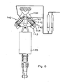
- Figure 6 shows a part of a floating drill rig system, having a travelling block 130, which maybe suspended from a cable or other raising/lowering device, and a top drive 135 suspended therefrom.
- a travelling block 130 which maybe suspended from a cable or other raising/lowering device, and a top drive 135 suspended therefrom.
- two compensators 140 arranged in an inverted V, their lower ends connected to the travelling block 110 and their upper ends both to a common connector 130 from which the top drive 120 is hanged.
- This arrangement of two compensators 140 according to the invention in a V-arrangement, basically symmetrical to the path of the member supported by the compensators, provides a practically attractive solution.
- the compensators 140 each have a piston 141 held non rotatable, whereas the cylinder 142 is rotated by an associated motor 143.
- a bearing is arranged between the cylinder 142 and the connector 144, which is connected to the travelling block 130.
- an inventive compensator is arranged at an angle with respect to the path of the member supported thereby.
- Fig. 7 shows application of a compensator 140 in a vessel mounted crane 150.
- the crane 150 has a boom 151, a topping cable 152 and winch 153, and a load carrying cable 154, and associated winch 155.
- the compensator 140 here is arranged to movably support a sheave assembly 156, here arranged on the boom 151, along which the cable 154 is guided, said cable supporting a crane hook 157
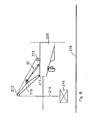
- Fig. 8 illustrates the nodding boom alternative.
- a part of a vessel 200 is shown having a crane arm 210, e.g. embodied as an A-frame, pivotable with respect to the vessel about a horizontal axis 211.
- a winch 212, cable 214 guided over a sheave assembly 213 on the (end of the) arm 210 supports a load 215 which is to be raised and/or lowered by the crane (e.g. for placement of the load onto the seabed 216).
- a compensator 40 is arranged between the vessel and the arm 210.
- Fig. 9 shows an alternative improved heave motion compensator 300 wherein the stick-slip effect is avoided in a different manner.
- the compensator 300 has a cylinder 301 with end covers 302, 303.
- a piston 304 arranged on a piston rod 305 is placed within the cylinder 301 and can oscillate in longitudinal direction within said cylinder 301.
- the piston rod 305 extends through an opening with surrounding seal 306 in the end cover 302.
- variable volume fluid chamber 309 is delimited in the cylinder 301, the volume depending on the axial position of the piston 304.
- the figure 9 shows that the chamber 309 is connected via a duct 315 to a pressurised fluid assembly here including an accumulator 316 having a variable volume hydraulic chamber 317 and a variable volume gas chamber 318 and a separation there between (here a free sliding piston 319).
- a pressurised fluid assembly here including an accumulator 316 having a variable volume hydraulic chamber 317 and a variable volume gas chamber 318 and a separation there between (here a free sliding piston 319).
- the chambers 309, 317 and the duct 315 are filled with hydraulic liquid, whereas the chamber 318 is gas filled.
- the chamber 318 is in turn connected to a bank of one or more gas reservoirs 320, which preferably have a large volume of gas therein.
- the gas can in practice be air or nitrogen.
- a gas pressure controller 322 is provided to set and adjust if desired the gas pressure within chamber 318 and in this manner set the pressure within the chamber 309. This pressure creates an inward force on the piston/piston rod-assembly.
- the piston 304 has a hydrostatic bearing which supports (basically centers) the piston with respect to the cylinder, wherein a narrow annular gap is maintained between the piston 304 and the cylinder 301.
- a pressurised fluid here hydraulic liquid, is supplied from a suitable source 340 through the piston (via conduit 325) to the hydrostatic bearing on the piston.
- the piston 304 here by way of example is provided with one or more annular pockets, here a tapering pocket 330, which is recessed with respect to the outer perimeter of the piston.
- the conduit 325 extends within the piston and through the piston rod.
- a continuous flow of liquid is provided to the hydrostatic bearing in order to maintain the spacing between the piston and the cylinder. As such an essentially “frictionless" compensator is obtained.
- the source 340 of pressurised fluid for the hydrostatic bearing can include an gas (air) source or a hydraulic liquid source. It can be envisaged that hydraulic liquid leaking from the hydrostatic bearing is collected in the compensator 300 (preferably within the chamber 310) and returned to the source 340, so as to create a "circulation circuit" for said liquid.
- a pressure controller can be provided to control the pressure of the fluid supplied to the hydrostatic bearing on the piston.
- the seal carrier is mounted on the piston so as to allow for a longitudinal oscillation of the seal carrier with respect to the piston independent from the longitudinal oscillations of the piston itself. This also allows to create a dynamic friction regime between the seal and the cylinder and thus avoids the transition between static friction and dynamic friction when the piston starts to move longitudinally. It will be appreciated that the same can be realised with an inner cylinder oscillation longitudinally within an outer cylinder, generally as an alternative to the figure 4 embodiment.
- the invention can also be understood so as to provide a heave motion compensator comprising a cylinder and a piston delimiting a variable volume fluid chamber in said cylinder, wherein said piston can oscillate within said cylinder, said piston being provided with a seal frictionally engaging said cylinder, characterised in that said compensator further includes a motor that imparts a relative motion between said seal and said cylinder independent from said piston oscillation.
- the same rotary drive system for the piston and piston rod can be integrated in a compensator which has two variable volume fluid chambers within said cylinder and separated by the piston.
- Such compensators are commonly used in active heave compensation systems, wherein further provision is made for a pressurised fluid assembly that allows to selective supply and discharge of fluid to and from said variable volume fluid chambers so as to cause controlled oscillation of said piston within said cylinder to obtain heave compensation.
- active systems commonly include one or more sensors providing input signals for a control unit, which governs the fluid supply and thus the position of the piston.
- the motion of the seal relative to the cylinder independent from the piston oscillations is advantageous for the behaviour of the compensation system.
Landscapes
- Engineering & Computer Science (AREA)
- Mechanical Engineering (AREA)
- Geology (AREA)
- Life Sciences & Earth Sciences (AREA)
- Mining & Mineral Resources (AREA)
- General Life Sciences & Earth Sciences (AREA)
- Fluid Mechanics (AREA)
- Environmental & Geological Engineering (AREA)
- Physics & Mathematics (AREA)
- Geochemistry & Mineralogy (AREA)
- Chemical & Material Sciences (AREA)
- Combustion & Propulsion (AREA)
- Ocean & Marine Engineering (AREA)
- Earth Drilling (AREA)
- Hydraulic Motors (AREA)
- Actuator (AREA)
- Massaging Devices (AREA)
- Basic Packing Technique (AREA)
Claims (19)
- Seegangbewegungausgleichsvorrichtung (30, 40, 70, 100, 140, 300) mit einem Zylinder (41) und einem Kolben (44), der in dem Zylinder (41) eine Fluidkammer (49) mit variablem Volumen begrenzt, wobei sich der Kolben (44) in dem Zylinder (41) hin und her bewegen kann, wobei der Kolben mit einer Dichtung (48) versehen ist, die reibschlüssig an den Zylinder angreift,
dadurch gekennzeichnet, dass die Ausgleichsvorrichtung ferner einen Motor (65) umfasst, der die Dichtung veranlasst, sich relativ zu dem Zylinder zu drehen. - Ausgleichsvorrichtung nach Anspruch 1, in welcher der Motor (65) so angeordnet ist, dass sie den Kolben dreht, und in welcher die Dichtung auf den Kolben montiert ist, so dass sich diese zusammen mit dem Kolben dreht.
- Ausgleichsvorrichtung nach Anspruch 1, in welcher der Motor (65) so angeordnet ist, dass dieser den Zylinder dreht, und in welcher der Kolben so ausgelegt ist, dass dieser nicht-drehbar montiert werden kann.
- Ausgleichsvorrichtung nach Anspruch 1, in welcher die Dichtung von einem Dichtungsträger getragen wird, welcher drehbar auf dem Kolben (44) angebracht ist, und in welcher der Motor den Dichtungsträger antreibt, so dass sich dieser um den Kolben dreht.
- Ausgleichsvorrichtung nach Anspruch 3, in welcher der Zylinder (41) ein Innenzylinder ist, welcher drehbar in einen Außenzylinder montiert ist, und in welcher der Außenzylinder so ausgelegt ist, dass dieser nicht-drehbar montiert werden kann.
- Seegangbewegungausgleichssystem mit einer Ausgleichsvorrichtung (30, 40 70, 100, 140, 300) nach einem oder mehreren der vorstehenden Ansprüche.
- Seegangbewegungausgleichssystem nach Anspruch 6, ferner mit einer Druckfluidanordnung, die mit der Fluidkammer mit variablem Volumen verbunden ist und so ausgelegt ist, dass diese darin einen gesteuerten Fluiddruck bereitstellt, möglichst einen konstanten Fluiddruck unabhängig von einer Kolbenbewegung.
- Seegangbewegungausgleichssystem nach Anspruch 7, in welchem die Druckfluidanordnung ein oder mehrere Gasreservoire (57) umfasst, welche in sich Druckgas speichern, wobei vorzugsweise die Fluidkammer mit variablem Volumen der Ausgleichsvorrichtung eine Gaskammer mit variablem Volumen ist, die mit ein oder mehreren Gasreservoirs (57) verbunden ist.
- Seegangbewegungausgleichssystem nach Anspruch 7, in welchem die Druckfluidanordnung einen Akkumulator (53) umfasst, der eine Hydraulikkammer mit variablem Volumen und eine Gaskammer mit variablem Volumen und eine Trennung zwischen diesen umfasst, wobei die Fluidkammer mit variablem Volumen mit der Hydraulikkammer mit variablem Volumen verbunden ist und mit einer Hydraulikflüssigkeit gefüllt ist, wobei die Gaskammer mit variablem Volumen mit Druckgas gefüllt ist.
- Seegangbewegungausgleichssystem nach Anspruch 7 und 9, in welchem die Gaskammer mit variablem Volumen des Akkumulators mit ein oder mehreren Gasreservoirs (57) verbunden ist.
- Seegangbewegungausgleichssystem nach Anspruch 6, in welchem die Ausgleichsvorrichtung zwei Fluidkammern mit variablem Volumen in dem Zylinder und getrennt durch den Kolben aufweist, wobei eine Druckfluidanordnung vorgesehen ist, welche eine selektive Zuführung und Entnahme von Fluid an und aus den Fluidkammern mit variablem Volumen erlaubt, um so eine gesteuerte Hin- und Herbewegung des Kolbens in dem Zylinder zu veranlassen, um einen Seegangbewegungausgleich zu erhalten.
- Wasserfahrzeug mit einem Seegangbewegungausgleichssystem nach ein oder mehreren der Ansprüche 6 bis 11.
- Wasserfahrzeug-Frachthandhabungssystem mit einem Seegangbewegungausgleichssystem nach ein oder mehreren der Ansprüche 6 bis 11.
- Schwimmendes Bohrplattformsystem mit einem Seegangbewegungausgleichssystem nach ein oder mehreren der Ansprüche 6 bis 11.
- Ausgleichsvorrichtung für einen Bohrstrang einer schwimmenden Bohrplattform mit einen Seegangbewegungausgleichssystem nach ein oder mehreren der Ansprüche 6 bis 11 und ausgelegt zur Anordnung zwischen einem Bohrstrang oder sonstigem Bohrgestänge und einer Bohrstrang-Hebeeinrichtung.
- Drahtgebundenes Erfassungssystem mit einem Kabel, einer zugehörigen Kabelwinde und ein oder mehreren Instrumenten, die in ein Bohrloch befördert werden können, wobei das System ferner ein Seegangbewegungausgleichssystem nach ein oder mehreren der Ansprüche 6 bis 11 umfasst.
- Schwimmendes Bohrfahrzeug mit einem gegenüber Seegangbewegung ausgeglichenen Bohrboden, wobei der Bohrboden relativ zum Wasserfahrzeug beweglich ist, um jegliche Seegangbewegung des Wasserfahrzeugs auszugleichen, wobei ein Seegangbewegungausgleichssystem nach ein oder mehreren der Ansprüche 6 bis 11 zwischen dem Wasserfahrzeug und dem Bohrboden angeordnet ist.
- Verfahren zum Ausgleich einer Seegangbewegung, insbesondere einer die Seegangbewegung ausgleichenden Lasthandhabung auf einem Wasserfahrzeug, in welchem eine Bewegungs-Ausgleichsvorrichtung nach ein oder mehreren der Ansprüche 1 bis 5 verwendet wird und in welchem die Dichtung so hergestellt wird, dass sich diese relativ zum Zylinder der Seegangbewegung-Ausgleichsvorrichtung derart dreht, dass die Reibung zwischen der Dichtung und dem Zylinder im Bereich der dynamischen Bewegungsreibung liegt.
- Seegangbewegungausgleichvorrichtung mit einem Zylinder und einem Kolben, welcher eine Fluidkammer mit variablem Volumen in dem Zylinder begrenzt, wobei sich der Kolben in dem Zylinder hin und her bewegen kann, wobei der Kolben mit einer reibschlüssig an den Zylinder angreifenden Dichtung versehen ist, dadurch gekennzeichnet, dass die Ausgleichsvorrichtung ferner einen Motor umfasst, der zwischen der Dichtung und dem Zylinder eine Relativbewegung unabhängig von der Kolbenbewegung erzeugt, wobei die Ausgleichsvorrichtung vorzugsweise so ausgelegt ist, dass eine relative Längsbewegung der Dichtung mit Bezug auf den Zylinder durch den Motor unabhängig von der Längsbewegung des Kolbens in dem Zylinder verursacht wird, und wobei vorzugsweise die Dichtung in einem Dichtungsträger montiert ist, wobei der Dichtungsträger auf dem Kolben montiert ist, um so eine Längsbewegung des Dichtungsträgers mit Bezug auf den Kolben unabhängig von den Längsbewegungen des Kolbens selbst zu erlauben.
Applications Claiming Priority (1)
| Application Number | Priority Date | Filing Date | Title |
|---|---|---|---|
| PCT/NL2006/000296 WO2007145503A1 (en) | 2006-06-16 | 2006-06-16 | Heave motion compensation |
Publications (2)
| Publication Number | Publication Date |
|---|---|
| EP2029423A1 EP2029423A1 (de) | 2009-03-04 |
| EP2029423B1 true EP2029423B1 (de) | 2009-12-23 |
Family
ID=37735202
Family Applications (1)
| Application Number | Title | Priority Date | Filing Date |
|---|---|---|---|
| EP06757801A Active EP2029423B1 (de) | 2006-06-16 | 2006-06-16 | Ausgleich für hebebewegung |
Country Status (7)
| Country | Link |
|---|---|
| US (1) | US20090133881A1 (de) |
| EP (1) | EP2029423B1 (de) |
| CN (1) | CN101466591B (de) |
| AT (1) | ATE452819T1 (de) |
| BR (1) | BRPI0621747A2 (de) |
| DE (1) | DE602006011373D1 (de) |
| WO (1) | WO2007145503A1 (de) |
Families Citing this family (41)
| Publication number | Priority date | Publication date | Assignee | Title |
|---|---|---|---|---|
| NO329688B1 (no) * | 2006-06-01 | 2010-11-29 | Nat Oilwell Norway As | Anordning ved heisesystem |
| WO2010062188A1 (en) * | 2008-11-26 | 2010-06-03 | Norwind As | A marine transport system and method for using same |
| GB2466983B (en) | 2009-01-16 | 2013-10-30 | Subsea 7 Ltd | A method and apparatus for supporting a load |
| US8640790B2 (en) * | 2009-03-09 | 2014-02-04 | Schlumberger Technology Corporation | Apparatus, system and method for motion compensation using wired drill pipe |
| GB0909800D0 (en) * | 2009-06-08 | 2009-07-22 | Kingsfield Engineering Services | Hoist system and method of hoisting |
| WO2011034422A2 (en) * | 2009-09-18 | 2011-03-24 | Itrec B.V. | Hoisting device |
| NO332769B2 (no) | 2009-12-15 | 2013-01-14 | Wellpartner As | Anordning ved sikkerhetskopling for rørstrengoppheng |
| NL2006248C2 (en) * | 2011-02-18 | 2012-08-21 | Itrec Bv | Active heave compensation system and method. |
| US8770272B2 (en) * | 2011-05-18 | 2014-07-08 | Halliburton Energy Services, Inc. | Managing tensile forces in a cable |
| CN102305039B (zh) * | 2011-08-15 | 2014-04-23 | 四川宏华石油设备有限公司 | 一种连续油管升沉补偿装置 |
| NO20111377A1 (no) * | 2011-10-11 | 2013-04-12 | Aker Mh As | Anordning for hivkompensering |
| NO335499B1 (no) * | 2011-11-25 | 2014-12-22 | Aker Mh As | Et bevegelseskompenseringssystem |
| NO334005B1 (no) * | 2012-03-12 | 2013-11-11 | Depro As | Anordning for kompensasjon av bølgebevirkede avstandsvariasjoner på borestreng |
| CN102606088B (zh) * | 2012-04-01 | 2014-04-09 | 西南石油大学 | 一种浮式钻井平台齿轮齿条位移倍增式钻柱升沉补偿装置 |
| WO2014023664A1 (en) * | 2012-08-10 | 2014-02-13 | Single Buoy Moorings Inc. | Vessel comprising a mooring connector with a heave compensator |
| AU2012241102B2 (en) * | 2012-10-15 | 2018-02-22 | Baker, Donna Ann | Installing an Anchor |
| RU2641390C2 (ru) * | 2012-10-17 | 2018-01-17 | Фэйрфилд Индастриз Инкорпорэйтед | Устройство, способ и варианты применения для контроля полезного груза |
| GB2503063B (en) * | 2013-02-07 | 2015-06-10 | Technip France | Passive heave compensator |
| WO2015007412A2 (en) * | 2013-07-16 | 2015-01-22 | Castor Drilling Solution As | Drilling rig arrangement |
| CN103344865B (zh) * | 2013-07-23 | 2015-09-09 | 山东大学(威海) | 浮体绳轮波浪发电陆地模拟试验平台 |
| EP2896589B1 (de) | 2014-01-17 | 2016-10-19 | SAL Offshore B.V. | Verfahren und Vorrichtung |
| NO343555B1 (no) * | 2014-12-02 | 2019-04-01 | Electrical Subsea & Drilling As | Anordning og fremgangsmåte ved aktiv hiv kompensering |
| NL2014212B1 (en) * | 2015-01-29 | 2017-01-11 | Ihc Holland Ie Bv | Compensator device |
| NO340789B1 (en) | 2015-10-08 | 2017-06-19 | Mhwirth As | Hoisting system |
| CN105329796B (zh) * | 2015-12-08 | 2017-08-11 | 南通大学 | 一种气动绞车主动升沉补偿装置及控制方法 |
| CN105370223B (zh) * | 2015-12-10 | 2017-06-23 | 吉林大学 | 一种钻杆螺纹丝扣保护器 |
| WO2017123237A1 (en) * | 2016-01-15 | 2017-07-20 | Halliburton Energy Services, Inc. | Offshore drilling platform vibration compensation using an iterative learning method |
| US10871032B2 (en) * | 2016-03-10 | 2020-12-22 | Halliburton Energy Services, Inc. | Device including a seal assembly |
| NO20160756A1 (en) * | 2016-05-04 | 2017-11-06 | Safelink As | Semi active heave compensator |
| NL2018378B1 (en) * | 2017-02-14 | 2018-09-06 | Itrec Bv | Heave motion compensation system |
| EP3363989B1 (de) * | 2017-02-16 | 2019-03-27 | National Oilwell Varco Norway AS | Bohreinheit mit einem elektrischen hiev-ausgleichssystem |
| US10683731B2 (en) * | 2017-08-14 | 2020-06-16 | Barry J. Nield | Drill rig and method for operating a drill rig |
| CN107720551B (zh) * | 2017-08-30 | 2019-12-20 | 武汉船用机械有限责任公司 | 一种吊点升沉补偿系统和补偿方法 |
| CN107985521B (zh) * | 2017-12-06 | 2019-07-02 | 定远县中林机械技术有限公司 | 一种主动平衡防浪船 |
| CN108032968B (zh) * | 2017-12-06 | 2019-09-24 | 定远县中林机械技术有限公司 | 一种主动平衡防浪船控制系统及控制方法 |
| CN108625801A (zh) * | 2018-04-27 | 2018-10-09 | 山东科技大学 | 深海采矿扬矿管升沉补偿装置 |
| EP3653561A1 (de) | 2018-11-13 | 2020-05-20 | NHLO Holding B.V. | (hub)ausgleichsvorrichtung, hubsystem, verfahren zum heben und teilesatz zum federausgleich eines hubsystems |
| CN113382921B (zh) * | 2018-12-07 | 2024-03-19 | 诺蒂-克拉夫特私人有限公司 | 具有俯仰和侧倾调节的悬架系统 |
| NL2022729B1 (en) * | 2019-03-12 | 2020-09-18 | Itrec Bv | Offshore system, vessel and method for performing subsea wellbore related activities |
| NL2028189B1 (en) * | 2021-05-11 | 2022-11-29 | Itrec Bv | Offloading an object from a heave motion compensated carrier of a vessel. |
| CN113700696B (zh) * | 2021-08-25 | 2022-11-18 | 江苏大学 | 一种后端独立供气的摩擦可调节气缸 |
Family Cites Families (27)
| Publication number | Priority date | Publication date | Assignee | Title |
|---|---|---|---|---|
| US3026850A (en) * | 1959-07-17 | 1962-03-27 | Coleman Engineering Company In | Fail-safe control for fluid pressure actuators |
| US3721293A (en) * | 1971-02-16 | 1973-03-20 | Vetco Offshore Ind Inc | Compensating and sensing apparatus for well bore drilling vessels |
| US3785249A (en) * | 1972-03-28 | 1974-01-15 | J Piroska | Power transmission system |
| US3905580A (en) * | 1973-10-09 | 1975-09-16 | Global Marine Inc | Heave compensator |
| US4167147A (en) * | 1976-01-19 | 1979-09-11 | Seatek Corp. | Method and apparatus for stabilizing a floating structure |
| US4176722A (en) * | 1978-03-15 | 1979-12-04 | Global Marine, Inc. | Marine riser system with dual purpose lift and heave compensator mechanism |
| US4232903A (en) * | 1978-12-28 | 1980-11-11 | Lockheed Missiles & Space Co., Inc. | Ocean mining system and process |
| US4365787A (en) * | 1979-12-28 | 1982-12-28 | Deepsea Ventures, Inc. | Pipe string lift system |
| US4702320A (en) * | 1986-07-31 | 1987-10-27 | Otis Engineering Corporation | Method and system for attaching and removing equipment from a wellhead |
| US4886397A (en) * | 1987-08-27 | 1989-12-12 | Cherbonnier T Dave | Dynamic load compensating system |
| US4858694A (en) * | 1988-02-16 | 1989-08-22 | Exxon Production Research Company | Heave compensated stabbing and landing tool |
| US4934870A (en) * | 1989-03-27 | 1990-06-19 | Odeco, Inc. | Production platform using a damper-tensioner |
| US4962817A (en) * | 1989-04-03 | 1990-10-16 | A.R.M. Design Development | Active reference system |
| US5209302A (en) * | 1991-10-04 | 1993-05-11 | Retsco, Inc. | Semi-active heave compensation system for marine vessels |
| CN2316452Y (zh) * | 1997-01-18 | 1999-04-28 | 玉环县石油机械厂 | 油管补偿器 |
| US6468082B1 (en) * | 1997-09-17 | 2002-10-22 | Advanced Motion Technologies, Llc | Motion-imparting apparatus |
| NO311374B1 (no) * | 1998-09-25 | 2001-11-19 | Eng & Drilling Machinery As | Fremgangsmate ved holding av stigeror under strekk og anordning for a sette stigeror under strekk |
| AU6372599A (en) * | 1999-10-19 | 2001-04-30 | Huisman Special Lifting Equipment B.V. | Hoisting mechanism, with compensator installed in a hoisting cable system |
| US20020197115A1 (en) * | 2001-06-22 | 2002-12-26 | Pgs Offshore Technology As | Pneumatic/hydrostatic riser tension |
| US6688814B2 (en) * | 2001-09-14 | 2004-02-10 | Union Oil Company Of California | Adjustable rigid riser connector |
| US6679504B2 (en) * | 2001-10-23 | 2004-01-20 | Liquidspring Technologies, Inc. | Seamless control of spring stiffness in a liquid spring system |
| JP2003139101A (ja) * | 2001-11-02 | 2003-05-14 | Teijin Seiki Co Ltd | サーボシリンダ |
| US20040099421A1 (en) * | 2002-11-27 | 2004-05-27 | Expro Americas, Inc. | Motion compensation system for watercraft connected to subsea conduit |
| US7231981B2 (en) * | 2003-10-08 | 2007-06-19 | National Oilwell, L.P. | Inline compensator for a floating drill rig |
| US7938598B2 (en) * | 2006-03-22 | 2011-05-10 | Itrec B.V. | Marine pipeline installation system and methods |
| GB0701600D0 (en) * | 2007-01-27 | 2007-03-07 | Deep Tek Ltd | Apparatus and method |
| US8225606B2 (en) * | 2008-04-09 | 2012-07-24 | Sustainx, Inc. | Systems and methods for energy storage and recovery using rapid isothermal gas expansion and compression |
-
2006
- 2006-06-16 CN CN200680054984.5A patent/CN101466591B/zh active Active
- 2006-06-16 US US12/304,969 patent/US20090133881A1/en not_active Abandoned
- 2006-06-16 WO PCT/NL2006/000296 patent/WO2007145503A1/en active Application Filing
- 2006-06-16 DE DE602006011373T patent/DE602006011373D1/de not_active Expired - Fee Related
- 2006-06-16 EP EP06757801A patent/EP2029423B1/de active Active
- 2006-06-16 AT AT06757801T patent/ATE452819T1/de not_active IP Right Cessation
- 2006-06-16 BR BRPI0621747-8A patent/BRPI0621747A2/pt not_active Application Discontinuation
Also Published As
| Publication number | Publication date |
|---|---|
| CN101466591B (zh) | 2013-03-20 |
| DE602006011373D1 (de) | 2010-02-04 |
| EP2029423A1 (de) | 2009-03-04 |
| US20090133881A1 (en) | 2009-05-28 |
| WO2007145503A1 (en) | 2007-12-21 |
| BRPI0621747A2 (pt) | 2012-07-24 |
| ATE452819T1 (de) | 2010-01-15 |
| CN101466591A (zh) | 2009-06-24 |
Similar Documents
| Publication | Publication Date | Title |
|---|---|---|
| EP2029423B1 (de) | Ausgleich für hebebewegung | |
| US4176722A (en) | Marine riser system with dual purpose lift and heave compensator mechanism | |
| US3390654A (en) | Stabilized offshore drilling apparatus | |
| US10081988B2 (en) | Heave compensation winches | |
| US4537533A (en) | Installation and levelling of subsea templates | |
| AU2017271305B2 (en) | Transportable inline heave compensator | |
| US11142287B2 (en) | System and method for compensation of motions of a floating vessel | |
| US20080251258A1 (en) | Tubing Support Assembly, Vessel And Method Of Deploying Tubing | |
| US20110005768A1 (en) | Method and apparatus for motion compensation during active intervention operations | |
| CN108839758A (zh) | 一种近海工程船载式平台用勘察装备收放装置及收放方法 | |
| CN208715418U (zh) | 一种近海工程船载式平台用勘察装备收放装置 | |
| CA2403015A1 (en) | Active deployment system and method | |
| CA3136399A1 (en) | A heave compensating system for a floating drilling vessel | |
| AU2012362727B2 (en) | Method and system for wireline intervention in a subsea well from a floating vessel | |
| CN109573861B (zh) | 一种基于永磁同步电机波浪补偿的海上浮吊系统 | |
| KR20180036204A (ko) | 회전식 유압 윈치 타입 히브모션 보상 시스템 | |
| KR101835286B1 (ko) | 크레인 겸용 브릿지 및 이를 포함하는 시추선 | |
| KR101775044B1 (ko) | 시추 호이스팅 장치 및 이를 구비한 해양 구조물 | |
| KR20160084609A (ko) | 드릴링 시스템 및 방법 | |
| KR20160062492A (ko) | 해양구조물의 히브모션 보상 제어시스템, 제어방법, 및 그 제어시스템을 갖는 해양구조물 | |
| WO2009134135A1 (en) | Hoisting device | |
| KR20160048415A (ko) | 드릴링 시스템 및 방법 | |
| KR20160048413A (ko) | 드릴링 시스템 및 방법 | |
| KR20160048414A (ko) | 드릴링 시스템 및 방법 | |
| WO2010067098A1 (en) | Assembly and method for supporting and deploying an object from a vessel |
Legal Events
| Date | Code | Title | Description |
|---|---|---|---|
| PUAI | Public reference made under article 153(3) epc to a published international application that has entered the european phase |
Free format text: ORIGINAL CODE: 0009012 |
|
| 17P | Request for examination filed |
Effective date: 20081215 |
|
| AK | Designated contracting states |
Kind code of ref document: A1 Designated state(s): AT BE BG CH CY CZ DE DK EE ES FI FR GB GR HU IE IS IT LI LT LU LV MC NL PL PT RO SE SI SK TR |
|
| AX | Request for extension of the european patent |
Extension state: AL BA HR MK RS |
|
| GRAP | Despatch of communication of intention to grant a patent |
Free format text: ORIGINAL CODE: EPIDOSNIGR1 |
|
| DAX | Request for extension of the european patent (deleted) | ||
| GRAS | Grant fee paid |
Free format text: ORIGINAL CODE: EPIDOSNIGR3 |
|
| GRAA | (expected) grant |
Free format text: ORIGINAL CODE: 0009210 |
|
| AK | Designated contracting states |
Kind code of ref document: B1 Designated state(s): AT BE BG CH CY CZ DE DK EE ES FI FR GB GR HU IE IS IT LI LT LU LV MC NL PL PT RO SE SI SK TR |
|
| REG | Reference to a national code |
Ref country code: GB Ref legal event code: FG4D |
|
| REG | Reference to a national code |
Ref country code: CH Ref legal event code: EP |
|
| REG | Reference to a national code |
Ref country code: IE Ref legal event code: FG4D |
|
| REF | Corresponds to: |
Ref document number: 602006011373 Country of ref document: DE Date of ref document: 20100204 Kind code of ref document: P |
|
| PG25 | Lapsed in a contracting state [announced via postgrant information from national office to epo] |
Ref country code: SE Free format text: LAPSE BECAUSE OF FAILURE TO SUBMIT A TRANSLATION OF THE DESCRIPTION OR TO PAY THE FEE WITHIN THE PRESCRIBED TIME-LIMIT Effective date: 20091223 Ref country code: FI Free format text: LAPSE BECAUSE OF FAILURE TO SUBMIT A TRANSLATION OF THE DESCRIPTION OR TO PAY THE FEE WITHIN THE PRESCRIBED TIME-LIMIT Effective date: 20091223 Ref country code: LT Free format text: LAPSE BECAUSE OF FAILURE TO SUBMIT A TRANSLATION OF THE DESCRIPTION OR TO PAY THE FEE WITHIN THE PRESCRIBED TIME-LIMIT Effective date: 20091223 |
|
| LTIE | Lt: invalidation of european patent or patent extension |
Effective date: 20091223 |
|
| PG25 | Lapsed in a contracting state [announced via postgrant information from national office to epo] |
Ref country code: SI Free format text: LAPSE BECAUSE OF FAILURE TO SUBMIT A TRANSLATION OF THE DESCRIPTION OR TO PAY THE FEE WITHIN THE PRESCRIBED TIME-LIMIT Effective date: 20091223 Ref country code: LV Free format text: LAPSE BECAUSE OF FAILURE TO SUBMIT A TRANSLATION OF THE DESCRIPTION OR TO PAY THE FEE WITHIN THE PRESCRIBED TIME-LIMIT Effective date: 20091223 Ref country code: PL Free format text: LAPSE BECAUSE OF FAILURE TO SUBMIT A TRANSLATION OF THE DESCRIPTION OR TO PAY THE FEE WITHIN THE PRESCRIBED TIME-LIMIT Effective date: 20091223 |
|
| PG25 | Lapsed in a contracting state [announced via postgrant information from national office to epo] |
Ref country code: AT Free format text: LAPSE BECAUSE OF FAILURE TO SUBMIT A TRANSLATION OF THE DESCRIPTION OR TO PAY THE FEE WITHIN THE PRESCRIBED TIME-LIMIT Effective date: 20091223 |
|
| PG25 | Lapsed in a contracting state [announced via postgrant information from national office to epo] |
Ref country code: EE Free format text: LAPSE BECAUSE OF FAILURE TO SUBMIT A TRANSLATION OF THE DESCRIPTION OR TO PAY THE FEE WITHIN THE PRESCRIBED TIME-LIMIT Effective date: 20091223 Ref country code: ES Free format text: LAPSE BECAUSE OF FAILURE TO SUBMIT A TRANSLATION OF THE DESCRIPTION OR TO PAY THE FEE WITHIN THE PRESCRIBED TIME-LIMIT Effective date: 20100403 Ref country code: IS Free format text: LAPSE BECAUSE OF FAILURE TO SUBMIT A TRANSLATION OF THE DESCRIPTION OR TO PAY THE FEE WITHIN THE PRESCRIBED TIME-LIMIT Effective date: 20100423 Ref country code: RO Free format text: LAPSE BECAUSE OF FAILURE TO SUBMIT A TRANSLATION OF THE DESCRIPTION OR TO PAY THE FEE WITHIN THE PRESCRIBED TIME-LIMIT Effective date: 20091223 Ref country code: PT Free format text: LAPSE BECAUSE OF FAILURE TO SUBMIT A TRANSLATION OF THE DESCRIPTION OR TO PAY THE FEE WITHIN THE PRESCRIBED TIME-LIMIT Effective date: 20100423 Ref country code: BG Free format text: LAPSE BECAUSE OF FAILURE TO SUBMIT A TRANSLATION OF THE DESCRIPTION OR TO PAY THE FEE WITHIN THE PRESCRIBED TIME-LIMIT Effective date: 20100323 |
|
| PG25 | Lapsed in a contracting state [announced via postgrant information from national office to epo] |
Ref country code: BE Free format text: LAPSE BECAUSE OF FAILURE TO SUBMIT A TRANSLATION OF THE DESCRIPTION OR TO PAY THE FEE WITHIN THE PRESCRIBED TIME-LIMIT Effective date: 20091223 Ref country code: CZ Free format text: LAPSE BECAUSE OF FAILURE TO SUBMIT A TRANSLATION OF THE DESCRIPTION OR TO PAY THE FEE WITHIN THE PRESCRIBED TIME-LIMIT Effective date: 20091223 Ref country code: SK Free format text: LAPSE BECAUSE OF FAILURE TO SUBMIT A TRANSLATION OF THE DESCRIPTION OR TO PAY THE FEE WITHIN THE PRESCRIBED TIME-LIMIT Effective date: 20091223 |
|
| PG25 | Lapsed in a contracting state [announced via postgrant information from national office to epo] |
Ref country code: CY Free format text: LAPSE BECAUSE OF FAILURE TO SUBMIT A TRANSLATION OF THE DESCRIPTION OR TO PAY THE FEE WITHIN THE PRESCRIBED TIME-LIMIT Effective date: 20091223 Ref country code: GR Free format text: LAPSE BECAUSE OF FAILURE TO SUBMIT A TRANSLATION OF THE DESCRIPTION OR TO PAY THE FEE WITHIN THE PRESCRIBED TIME-LIMIT Effective date: 20100324 |
|
| PLBE | No opposition filed within time limit |
Free format text: ORIGINAL CODE: 0009261 |
|
| STAA | Information on the status of an ep patent application or granted ep patent |
Free format text: STATUS: NO OPPOSITION FILED WITHIN TIME LIMIT |
|
| 26N | No opposition filed |
Effective date: 20100924 |
|
| PG25 | Lapsed in a contracting state [announced via postgrant information from national office to epo] |
Ref country code: DK Free format text: LAPSE BECAUSE OF FAILURE TO SUBMIT A TRANSLATION OF THE DESCRIPTION OR TO PAY THE FEE WITHIN THE PRESCRIBED TIME-LIMIT Effective date: 20091223 Ref country code: MC Free format text: LAPSE BECAUSE OF NON-PAYMENT OF DUE FEES Effective date: 20100630 |
|
| REG | Reference to a national code |
Ref country code: CH Ref legal event code: PL |
|
| REG | Reference to a national code |
Ref country code: FR Ref legal event code: ST Effective date: 20110228 |
|
| PG25 | Lapsed in a contracting state [announced via postgrant information from national office to epo] |
Ref country code: IT Free format text: LAPSE BECAUSE OF FAILURE TO SUBMIT A TRANSLATION OF THE DESCRIPTION OR TO PAY THE FEE WITHIN THE PRESCRIBED TIME-LIMIT Effective date: 20091223 |
|
| PG25 | Lapsed in a contracting state [announced via postgrant information from national office to epo] |
Ref country code: IE Free format text: LAPSE BECAUSE OF NON-PAYMENT OF DUE FEES Effective date: 20100616 Ref country code: DE Free format text: LAPSE BECAUSE OF NON-PAYMENT OF DUE FEES Effective date: 20110101 Ref country code: CH Free format text: LAPSE BECAUSE OF NON-PAYMENT OF DUE FEES Effective date: 20100630 Ref country code: LI Free format text: LAPSE BECAUSE OF NON-PAYMENT OF DUE FEES Effective date: 20100630 |
|
| PG25 | Lapsed in a contracting state [announced via postgrant information from national office to epo] |
Ref country code: FR Free format text: LAPSE BECAUSE OF NON-PAYMENT OF DUE FEES Effective date: 20100630 |
|
| PG25 | Lapsed in a contracting state [announced via postgrant information from national office to epo] |
Ref country code: LU Free format text: LAPSE BECAUSE OF NON-PAYMENT OF DUE FEES Effective date: 20100616 Ref country code: HU Free format text: LAPSE BECAUSE OF FAILURE TO SUBMIT A TRANSLATION OF THE DESCRIPTION OR TO PAY THE FEE WITHIN THE PRESCRIBED TIME-LIMIT Effective date: 20100624 |
|
| PG25 | Lapsed in a contracting state [announced via postgrant information from national office to epo] |
Ref country code: TR Free format text: LAPSE BECAUSE OF FAILURE TO SUBMIT A TRANSLATION OF THE DESCRIPTION OR TO PAY THE FEE WITHIN THE PRESCRIBED TIME-LIMIT Effective date: 20091223 |
|
| PGFP | Annual fee paid to national office [announced via postgrant information from national office to epo] |
Ref country code: NL Payment date: 20230622 Year of fee payment: 18 |
|
| PGFP | Annual fee paid to national office [announced via postgrant information from national office to epo] |
Ref country code: GB Payment date: 20230622 Year of fee payment: 18 |