EP2028670A2 - Feder-Antriebsvorrichtung für Luftleistungsschalter - Google Patents
Feder-Antriebsvorrichtung für Luftleistungsschalter Download PDFInfo
- Publication number
- EP2028670A2 EP2028670A2 EP08162665A EP08162665A EP2028670A2 EP 2028670 A2 EP2028670 A2 EP 2028670A2 EP 08162665 A EP08162665 A EP 08162665A EP 08162665 A EP08162665 A EP 08162665A EP 2028670 A2 EP2028670 A2 EP 2028670A2
- Authority
- EP
- European Patent Office
- Prior art keywords
- switch
- micro switch
- charging device
- spring
- compressor
- Prior art date
- Legal status (The legal status is an assumption and is not a legal conclusion. Google has not performed a legal analysis and makes no representation as to the accuracy of the status listed.)
- Granted
Links
Images


Classifications
-
- H—ELECTRICITY
- H01—ELECTRIC ELEMENTS
- H01H—ELECTRIC SWITCHES; RELAYS; SELECTORS; EMERGENCY PROTECTIVE DEVICES
- H01H3/00—Mechanisms for operating contacts
- H01H3/22—Power arrangements internal to the switch for operating the driving mechanism
- H01H3/30—Power arrangements internal to the switch for operating the driving mechanism using spring motor
- H01H3/3005—Charging means
- H01H3/3026—Charging means in which the closing spring charges the opening spring or vice versa
-
- H—ELECTRICITY
- H01—ELECTRIC ELEMENTS
- H01H—ELECTRIC SWITCHES; RELAYS; SELECTORS; EMERGENCY PROTECTIVE DEVICES
- H01H33/00—High-tension or heavy-current switches with arc-extinguishing or arc-preventing means
- H01H33/02—Details
- H01H33/28—Power arrangements internal to the switch for operating the driving mechanism
-
- H—ELECTRICITY
- H01—ELECTRIC ELEMENTS
- H01H—ELECTRIC SWITCHES; RELAYS; SELECTORS; EMERGENCY PROTECTIVE DEVICES
- H01H3/00—Mechanisms for operating contacts
- H01H3/22—Power arrangements internal to the switch for operating the driving mechanism
- H01H3/30—Power arrangements internal to the switch for operating the driving mechanism using spring motor
- H01H3/3005—Charging means
- H01H3/3015—Charging means using cam devices
-
- H—ELECTRICITY
- H01—ELECTRIC ELEMENTS
- H01H—ELECTRIC SWITCHES; RELAYS; SELECTORS; EMERGENCY PROTECTIVE DEVICES
- H01H33/00—High-tension or heavy-current switches with arc-extinguishing or arc-preventing means
- H01H33/02—Details
- H01H33/28—Power arrangements internal to the switch for operating the driving mechanism
- H01H33/40—Power arrangements internal to the switch for operating the driving mechanism using spring motor
-
- H—ELECTRICITY
- H01—ELECTRIC ELEMENTS
- H01H—ELECTRIC SWITCHES; RELAYS; SELECTORS; EMERGENCY PROTECTIVE DEVICES
- H01H33/00—High-tension or heavy-current switches with arc-extinguishing or arc-preventing means
- H01H33/02—Details
- H01H33/42—Driving mechanisms
-
- H—ELECTRICITY
- H01—ELECTRIC ELEMENTS
- H01H—ELECTRIC SWITCHES; RELAYS; SELECTORS; EMERGENCY PROTECTIVE DEVICES
- H01H3/00—Mechanisms for operating contacts
- H01H3/22—Power arrangements internal to the switch for operating the driving mechanism
- H01H3/30—Power arrangements internal to the switch for operating the driving mechanism using spring motor
- H01H2003/3063—Decoupling charging handle or motor at end of charging cycle or during charged condition
-
- H—ELECTRICITY
- H01—ELECTRIC ELEMENTS
- H01H—ELECTRIC SWITCHES; RELAYS; SELECTORS; EMERGENCY PROTECTIVE DEVICES
- H01H3/00—Mechanisms for operating contacts
- H01H3/22—Power arrangements internal to the switch for operating the driving mechanism
- H01H3/30—Power arrangements internal to the switch for operating the driving mechanism using spring motor
- H01H2003/3073—Indication of the charge on the spring motor
Definitions
- the following description relates generally to a spring charging device of air circuit breaker, and more particularly to a spring charging device of air circuit breaker mounted with at least one or more micro switches and a switch lever for turning on/off the micro switch capable of compressing a connection spring of an air circuit breaker and notifying completion of the compression of the connection spring when the charging is completed.
- an ACB air circuit breaker
- a stationary contactor and a movable contactor movable to a connected position for closing a conducted circuit by contacting the stationary contactor and to an interruption (trip) position for opening the conducted circuit by being separated from the stationary contactor, and allow the stationary contactor and the movable contactor to be contacted at all times for flowing the current, but when an abnormal over-current (a large current caused by i.e., short circuit and ground fault) generated at an electric circuit such as a power transmission/distribution line and private power transforming facilities occurs, the movable contactor is swiftly separated from the stationary contactor to interrupt the current from flowing to thereby protect load units such as a motor and a transformer and an electric line against an abnormal current.
- the ACB also exposes the stationary and movable contactors to pull in the compressed air and to distinguish the arc generated during the occurrence of abnormal current.
- the ACB is utilized for connecting a high-voltage current to or interrupting the current from a power station or distributing station, and is mounted, if necessary, with an actuator for swiftly interrupting or separating a contact point between the stationary contactor and the movable contactor.
- the driving method of the actuator is largely classified into a manual manipulation method, a solenoid manipulation method and an electric spring manipulation method.
- an interruption spring is elastically connected to one side of a cam axle mounted with a charging cam connected to a link connected to a movable contactor, and a manual charging device rotating the cam axle using a manual lever or an electric charging device using a motor is connected to the cam axle.
- the cam axle is rotated while a rotation moment-added main energy is maximally accumulated in the interruption spring using the charging device. If necessary, a lock is released to rotate the cam axle using the accumulated energy of the interruption spring and sequentially-meshed link separates the movable contactor from the stationary contactor to interrupt the current.
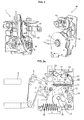
- FIG. 1 is a perspective view illustrating configuration of a typical ACB and FIGS. 2a , 2b and 2c are schematic views sequentially illustrating an operational state of an actuator mechanism.
- the typical ACB includes a connection spring (hereinafter referred to as spring. 11) selectively separating or connecting a contact point between a stationary contactor (3) and a movable contactor (5) for opening and closing a conducted circuit, an actuator mechanism (1) including a linkage (15), an interruption spring (21) and a cam axle (30), a driving motor (50. hereinafter referred to as motor) rotating the cam axle (30), and a charging device (40) including a decelerating gear assembly (60) and an output gear (70).
- a connection spring hereinafter referred to as spring. 11
- spring selectively separating or connecting a contact point between a stationary contactor (3) and a movable contactor (5) for opening and closing a conducted circuit
- an actuator mechanism (1) including a linkage (15), an interruption spring (21) and a cam axle (30), a driving motor (50. hereinafter referred to as motor) rotating the cam axle (30), and a charging device (40) including a decelerating gear assembly (60) and an output gear
- FIG.2a illustrates an initial state of the actuator mechanism (1) where the contact point between the stationary contactor (3) and the movable contactor (5) are opened.
- the cam axle (30) is rotated by the driving motor (50) or a charging handle (not shown), and a driver lever (16) is rotated by rotation of a charging cam (12) meshed with the cam axle to compress the spring (11) to be in a state illustrated in FIG.2b , i.e., in the state of charging completed.
- the changing cam (12) accumulated by the spring (11) maintains an equilibrium of force due to an ON lever (14) contacting a connection latch (13).
- An ON coupling (17) contacting a connection solenoid (not shown) is in a position capable of rotating the ON lever (14).
- connection latch (13) releases the charging cam (12)to allow the accumulated force of the spring (11) to be transmitted to the linkage (15) via a driver lever (16).
- An open/close axis (10) is rotated clockwise to allow contact points of the stationary contactor (3) and the movable contactor (5) to be contacted therebetween via an open/close lever (20) rotating in conjunction with the open/close axis (10) and to elongate the interruption spring (21), the state of which is illustrated in FIG.2c .
- the motor (50) for rotating the cam axle (30) is controlled by a motor-controlling micro switch (not shown) provided at the charging device.
- the motor-controlling micro switch causes the motor (50) to be applied with a driving current for charging (compression) of the spring (11), allowing the rotational force of the motor (50) to be transmitted to the cam axle (30).
- the driving current applied to the motor (50) is interrupted.
- the motor-controning micro switch is basically structured to apply a driving current to the motor (50), such that, although the motor-controlling micro switch may be additionally configured with a separate distributing circuit to allow the user to be notified of the completion of charging, it is not advisable to install a separate distributing circuit configuration on the motor-controlling micro switch due to complication of the distributing circuit and possible erroneous operation of the motor (50).
- This disclosure is provided to solve the aforementioned disadvantages and an object of this disclosure is to provide a spring charging device of air circuit breaker, wherein the spring charging device is mounted with at least one or more micro switches and a switch lever for turning on/off the micro switch capable of compressing a connection spring of the air circuit breaker and notifying completion of the compression of the connection spring when the charging is completed, thereby enhancing the efficiency in operation of the air circuit breaker by a user (an operator).
- a spring charging device of air circuit breaker comprises: first and second plates connected via a plurality of shafts each in a predetermined discrete distance; a driving motor mounted at the first plate; an output gear formed at an circumferential surface thereof with a predetermined groove and mounted at the second plate for connecting to a cam axle for charging a connection spring; a decelerating gear assembly connecting the driving motor to the output gear for transmitting a rotational force of the driving motor to the output gear; a driving motor-controlling micro switch mounted at one side of the second plate; a first micro switch mounted at an upper surface of the driving motor-controlling micro switch; display means for being electrically connected with the first micro switch; and a switch lever formed with a gear contactor provided at one end thereof with a projection contacting a circumferential surface of the output gear, a hinge unit bent from the other end of the gear contactor and provided at a distal end thereof with a hinge through hole, and a switch compressor vertically extended relative to the gear contactor and the hinge unit, where
- Implementations of this aspect may include one or more of the following features.
- the switch compressor may increase thickness thereof as being distanced from the gear contactor to lower a bottom surface selectively contacting the micro switches.
- the switch compressor may be provided with a first projection for complementing the compressed pressure relative to the first micro switch.
- the switch lever may further comprise a first rib for preventing the switch compressor from being bent by being horizontally and extensively formed from the switch compressor to be connected to the hinge unit.
- the switch lever may be further formed with a second rib for preventing the switch compressor from being bent by being vertically and extensively formed from the switch compressor to be connected to the gear contactor.
- the first micro switch may be further formed at an upper surface thereof with a second micro switch connected to a separate display means, where the switch compressor may be formed with a second projection for complementing the compressed pressure relative to the second micro switch.
- An insulation plate may be interposed between the second plate and the driving motor-controning micro switch.
- An insulation plate may be interposed between the first micro switch and the driving motor-controlling micro switch.
- An insulation plate may be interposed between the first micro switch and the second micro switch.
- the advantageous effect of the spring charging device of air circuit breaker is such that the spring charging device is mounted with at least one or more micro switches and a switch lever for turning on/off the micro switch capable of compressing a connection spring of the air circuit breaker and notifying completion of the compression of the spring when the charging is completed, thereby enhancing the efficiency in operation of the air circuit breaker by a user (an operator).
- FIG.3 is a perspective view of a connection spring charging device of an air circuit breaker according to an exemplary implementation
- FIG.4 is a partial perspective view of arranged relationship of an output gear, a switch lever and a driving motor-controlling micro switch illustrated in FIG.3 ,
- a spring charging device (100) of air circuit breaker includes first and second plates (111, 112) connected via a plurality of shafts each in a predetermined discrete distance.
- the first plate (111) is mounted with a driving motor (120. hereinafter referred to as motor) for providing a rotational force for rotating a cam axle (30) for compressing a connection spring (11. hereinafter referred to as spring, see FIGS. 2a , 2b and 2c ).
- a driving motor 120. hereinafter referred to as motor
- a connection spring 11. hereinafter referred to as spring, see FIGS. 2a , 2b and 2c ).
- Unexplained reference numeral 135 defines a cam axle insertion groove for inserting the cam axle (30).
- a decelerating gear assembly (190. see FIG.6a ) for connecting the motor (120) to the output gear (130) to transmit a rotational force of the motor (120) to the output gear (130).
- the second plate (112) is mounted at one side thereof with a motor controlling micro switch (150) controlling the operation of the motor (120) by applying or blocking a driving current to the motor (120) in response to the operation of a switch lever (140. described later).
- An insulation plate (180) for insulating the motor controlling micro switch (150) is interposed between the motor controlling micro switch (150) and the second plate (112).
- the motor controlling micro switch (150) is mounted thereon with a first micro switch (160) turned on/off by operation of the switch lever (140) for notifying a user of completion of charging by applying a driving current to display means (not shown) such as a buzzer or a lamp when the spring (11) is compressed to complete the charging.
- An insulation plate (180) is interposed between the first micro switch (160) and the motor controlling micro switch (150) for insulation of the first micro switch (160).
- the first micro switch (160) may be additionally mounted thereon with a second micro switch (170).
- the second micro switch (170) is turned on/off in response to operation of the switch lever (140) as the first micro switch (160).
- the second micro switch may be connected to another display means (not shown) such as a buzzer or a lamp provided separately from the display means (not shown) such as a buzzer or a lamp connected to the first micro switch (160) to notifying the completion of charging to a second user (operator), or may be connected to another operator provided inside the system of the air circuit breaker, for example, to a connection solenoid for connecting the circuit breaker when the charging is completed as illustrated in FIG.2b .
- another display means such as a buzzer or a lamp provided separately from the display means (not shown) such as a buzzer or a lamp connected to the first micro switch (160) to notifying the completion of charging to a second user (operator)
- another operator provided inside the system of the air circuit breaker, for example, to a connection solenoid for connecting the circuit breaker when the charging is completed as illustrated in FIG.2b .
- an insulator (180) may be interposed between the first micro switch (160) and the second micro switch (170) for insulating the second micro switch (170).
- FIG.5a and FIG. 5b are a perspective view of a switch lever illustrated in FIG.4
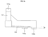
- FIG. 5c is a lateral view of a switch lever illustrated in FIG.5a .
- the switch lever (140) is formed with a gear contactor (141) provided at one end thereof with a projection (141a) contacting a circumferential surface (131) of the output gear (130), a hinge unit (143) bent from the other end of the gear contactor (141) and provided at a distal end thereof with a hinge through hole (143a), and a switch compressor (145) vertically extended relative to the gear contactor (141) and the hinge unit (143), whereby the switch lever (140) is rotatably mounted on the second plate (112) via a hinge axle (13) provided at one side of the second plate (112).
- the switch compressor (145) may press each button (not shown) of the motor controlling micro switch (150) and the first micro switch (160), while the projection (141a) provided at the gear contractor (141) of the switch lever (140) contacts the circumferential surface (131) of the output gear (130). Under a certain circumstance, the switch compressor (145) may press buttons (not shown) of the second micro switch (170), such that the compressing pressure pressing each button of the micro switches (150, 160, 170) may be weakened as being distanced from the gear contactor (141).
- the switch compressor (145) increases in thickness thereof as being distanced from the gear contactor (141), as illustrated in FIG.5c , to lower a bottom surface contacting each button of the micro switches (150, 160, 170).
- the switch compressor (145) may be further formed with a second projection (145b) depressing the second micro switch (170) and the first projection (145a) depressing the first micro switch (160) while the projection (141a) provided at the gear contactor (141) of the switch lever (140) abuts the circumferential surface (131) of the output gear (130).
- the switch compressor (145) presses the motor controlling micro switch (150) and each button of the first micro switch (160), and in some cases, presses buttons of the second micro switch (170), such that the switch compressor (145) tends to get bent in use as being distanced from the gear contactor (141).
- the switch lever (140) is formed with a first rib (146) horizontally and extensively formed from the switch compressor (145) to be connected to the hinge unit (143), and a second rib (147) vertically and extensively formed from the switch compressor (145) to be connected to the gear contactor (141).
- FIGS.6a and 6b are operational constitutional views sequentially illustrating an operational state of a spring charging device of an air circuit breaker according to an exemplary implementation.
- FIG.6a describes a state in which the motor (120) is driven to rotate the output gear (130) clockwise, thereby rotating the cam axle (30) to charge the spring (11. see FIG.2a ).
- FIG.6a illustrates a state where the projection (141a) provided at the gear contactor (141) of the switch lever (140) is brought into contact with the circumferential surface (131) of the output gear (130), and a left distal end of the switch compressor (145) compresses the button of the motor controlling micro switch (150) to prompt the motor controlling micro switch (150) to apply a current to the motor (120), thereby rotating the output gear (130) to rotate clockwise, as illustrated in FIG.5a .
- An internal circuit of the motor controlling micro switch (150) maintains a state of open contact point under a normal situation, but changes the state to a closed contact point to apply a driving current to the motor (120) by allowing the button to be pressed by the left distal end of the switch compressor (145).
- an internal circuit of the first and second micro switches (160, 170) disposed on the same axis as that of the motor controlling micro switch (150) maintains a closed contact point under a normal situation, but changes the state to that of open contact point to interrupt the current applied to the solenoid that connects the display means such as a buzzer or a lamp by being changed to the open contact point when each button is pressed by the switch compressor (145) or by the first and second projections (145a, 145b) provided at the switch compressor (145).
- buttons of the motor controlling micro switch (150) are released to allow the internal circuit to be changed to the state of open contact point, whereby the driving current applied to the motor (120) is interrupted to stop the driving of the motor (120).
- the supplied rotational force is removed to stop the output gear (130) and the cam axle (30) ceases to rotate.
- the projection piece (133) formed at the circumferential surface (131) of the output gear (130) is hitched by a stopper (114) provided at the second plate (112), whereby the possibility of the output gear (130) being rotated by a barely operated rotational force is interrupted.
- each button of the first and second micro switches (160, 170) disposed on the same axis as that of the motor controlling micro switch (150) is released of being compressed, and the internal circuit of the first and second micro switches (160, 170) is changed to a state of closed contact point to cause the display means such as a buzzer or a lamp to be applied with a current, whereby a user (an operator) is notified of the charging completion, or to cause the solenoid to be applied with a current, thereby connecting the circuit breaker as illustrated in FIG.2c .
- the spring charging device of air circuit breaker is mounted with at least one or more micro switches (160, 170) and a switch lever (140) for turning on/off the micro switches (160, 170) capable of compressing the spring and notifying completion of the compression of the spring when the charging is completed, thereby enhancing the efficiency in operation of the air circuit breaker by a user (an operator).
Landscapes
- Driving Mechanisms And Operating Circuits Of Arc-Extinguishing High-Tension Switches (AREA)
- Mechanisms For Operating Contacts (AREA)
- Connection Of Motors, Electrical Generators, Mechanical Devices, And The Like (AREA)
- Electric Propulsion And Braking For Vehicles (AREA)
- Breakers (AREA)
Applications Claiming Priority (1)
| Application Number | Priority Date | Filing Date | Title |
|---|---|---|---|
| KR1020070083504A KR100850422B1 (ko) | 2007-08-20 | 2007-08-20 | 기중차단기의 투입스프링 차징장치 |
Publications (3)
| Publication Number | Publication Date |
|---|---|
| EP2028670A2 true EP2028670A2 (de) | 2009-02-25 |
| EP2028670A3 EP2028670A3 (de) | 2010-08-25 |
| EP2028670B1 EP2028670B1 (de) | 2015-07-08 |
Family
ID=39881183
Family Applications (1)
| Application Number | Title | Priority Date | Filing Date |
|---|---|---|---|
| EP08162665.7A Active EP2028670B1 (de) | 2007-08-20 | 2008-08-20 | Feder-Antriebsvorrichtung für Luftleistungsschalter |
Country Status (6)
| Country | Link |
|---|---|
| EP (1) | EP2028670B1 (de) |
| KR (1) | KR100850422B1 (de) |
| CN (1) | CN101373685B (de) |
| ES (1) | ES2550252T3 (de) |
| MY (1) | MY143293A (de) |
| RU (1) | RU2401471C2 (de) |
Cited By (3)
| Publication number | Priority date | Publication date | Assignee | Title |
|---|---|---|---|---|
| EP2575150A1 (de) * | 2011-09-30 | 2013-04-03 | Schneider Electric Industries SAS | Vorrichtung zur Entkupplung des Motorantriebs von der Federspannvorrichtung des Kontaktantriebs in einem Schutzschalter und Schutzschalter mit einer entsprechenden Vorrichtung |
| WO2016016011A1 (de) * | 2014-07-31 | 2016-02-04 | Siemens Aktiengesellschaft | Federspeicherantrieb sowie verfahren zur überwachung eines federspeicherantriebes |
| CN104021974B (zh) * | 2014-06-19 | 2017-02-22 | 中能电气股份有限公司 | 一种用于负荷开关的夹板式操作机构 |
Families Citing this family (10)
| Publication number | Priority date | Publication date | Assignee | Title |
|---|---|---|---|---|
| CN103779143B (zh) * | 2014-02-19 | 2015-12-02 | 合肥同智机电控制技术股份有限公司 | 用于交流智能配电控制模块的操纵杆 |
| KR101769195B1 (ko) * | 2015-04-13 | 2017-08-18 | 엘에스산전 주식회사 | 회로 차단기 |
| CN106067395B (zh) * | 2015-04-21 | 2018-12-14 | 现代电力与能源系统株式会社 | 限位开关以及断路器 |
| KR20160130051A (ko) | 2015-04-30 | 2016-11-10 | 현대중공업 주식회사 | 차징상태 표시장치 |
| KR101740941B1 (ko) | 2015-11-12 | 2017-06-01 | 현대일렉트릭앤에너지시스템(주) | 회로차단기의 투입스프링 차징 장치 |
| ITUB20160760A1 (it) * | 2016-02-15 | 2017-08-15 | Bticino Spa | Interruttore azionato a pulsante con organo oscillante di controllo |
| KR101839091B1 (ko) * | 2016-12-05 | 2018-03-16 | 엘에스산전 주식회사 | 기중 차단기의 차징장치 |
| KR101897737B1 (ko) * | 2017-04-18 | 2018-09-12 | 엘에스산전 주식회사 | 회로차단기의 차징기어 어셈블리 및 그 제조방법 |
| CN107845513B (zh) * | 2017-12-07 | 2020-01-31 | 西门子中压开关技术(无锡)有限公司 | 电动操作机构及开关装置 |
| CN109599300B (zh) * | 2018-11-08 | 2021-02-26 | 谢垚峰 | 以压合支架走道配合而稳定的断路器的闭合弹簧加载装置 |
Citations (1)
| Publication number | Priority date | Publication date | Assignee | Title |
|---|---|---|---|---|
| US4146764A (en) | 1976-10-22 | 1979-03-27 | Gould Inc. | Circuit breaker ratchet and pawl spring charging system |
Family Cites Families (14)
| Publication number | Priority date | Publication date | Assignee | Title |
|---|---|---|---|---|
| US3729065A (en) * | 1971-03-05 | 1973-04-24 | Gen Electric | Means for charging a stored energy circuit breaker closing device |
| DE2236788B2 (de) * | 1972-07-24 | 1975-05-28 | Siemens Ag, 1000 Berlin Und 8000 Muenchen | Antriebsvorrichtung für elektrische Schaltgeräte |
| US4251702A (en) * | 1979-06-25 | 1981-02-17 | General Electric Company | Circuit breaker having multiple spring actuating mechanisms |
| US4245140A (en) * | 1979-06-25 | 1981-01-13 | General Electric Company | Manual and motor operated circuit breaker |
| JP3095590B2 (ja) * | 1993-09-24 | 2000-10-03 | 株式会社東芝 | 回路遮断器 |
| US5906271A (en) * | 1995-08-07 | 1999-05-25 | General Electric Company | Means of remote charge indication for high ampere-rated circuit breakers |
| FR2766960B1 (fr) * | 1997-07-31 | 1999-09-24 | Gec Alsthom T & D Ag | Dispositif de commande rapide pour un appareil de connexion a haute tension, notamment un sectionneur de terre |
| FR2785444B1 (fr) * | 1998-10-30 | 2000-12-15 | Schneider Electric Ind Sa | Appareillage de coupure comportant un organe mecanique de visualisation a trois positions |
| FR2806523B1 (fr) * | 2000-03-17 | 2002-06-14 | Ge Power Controls France | Commande electrique de disjoncteur |
| CA2328009C (en) * | 2000-10-10 | 2009-05-12 | S&C Electric Company | Operating mechanism with improved input drive arrangement for switches and circuit interrupters |
| JP4262012B2 (ja) * | 2003-07-31 | 2009-05-13 | ティケイディ株式会社 | 開閉器用操作器 |
| KR200378090Y1 (ko) | 2004-12-22 | 2005-03-14 | 현대중공업 주식회사 | 기중차단기 작동기구 |
| KR200411539Y1 (ko) | 2005-12-30 | 2006-03-15 | 엘에스산전 주식회사 | 진공차단기 |
| KR100771922B1 (ko) * | 2006-10-17 | 2007-11-01 | 엘에스산전 주식회사 | 기중 차단기 |
-
2007
- 2007-08-20 KR KR1020070083504A patent/KR100850422B1/ko active Active
-
2008
- 2008-08-18 MY MYPI20083150A patent/MY143293A/en unknown
- 2008-08-19 RU RU2008133881/09A patent/RU2401471C2/ru active
- 2008-08-20 CN CN2008102108496A patent/CN101373685B/zh active Active
- 2008-08-20 EP EP08162665.7A patent/EP2028670B1/de active Active
- 2008-08-20 ES ES08162665.7T patent/ES2550252T3/es active Active
Patent Citations (1)
| Publication number | Priority date | Publication date | Assignee | Title |
|---|---|---|---|---|
| US4146764A (en) | 1976-10-22 | 1979-03-27 | Gould Inc. | Circuit breaker ratchet and pawl spring charging system |
Cited By (4)
| Publication number | Priority date | Publication date | Assignee | Title |
|---|---|---|---|---|
| EP2575150A1 (de) * | 2011-09-30 | 2013-04-03 | Schneider Electric Industries SAS | Vorrichtung zur Entkupplung des Motorantriebs von der Federspannvorrichtung des Kontaktantriebs in einem Schutzschalter und Schutzschalter mit einer entsprechenden Vorrichtung |
| FR2980909A1 (fr) * | 2011-09-30 | 2013-04-05 | Schneider Electric Ind Sas | Dispositif de debrayage de la motorisation du dispositif de rearmement du dispositif de fermeture des contacts dans un appareil de protection electrique et appareil le comportant |
| CN104021974B (zh) * | 2014-06-19 | 2017-02-22 | 中能电气股份有限公司 | 一种用于负荷开关的夹板式操作机构 |
| WO2016016011A1 (de) * | 2014-07-31 | 2016-02-04 | Siemens Aktiengesellschaft | Federspeicherantrieb sowie verfahren zur überwachung eines federspeicherantriebes |
Also Published As
| Publication number | Publication date |
|---|---|
| EP2028670B1 (de) | 2015-07-08 |
| KR100850422B1 (ko) | 2008-08-04 |
| CN101373685A (zh) | 2009-02-25 |
| MY143293A (en) | 2011-04-15 |
| RU2008133881A (ru) | 2010-02-27 |
| EP2028670A3 (de) | 2010-08-25 |
| RU2401471C2 (ru) | 2010-10-10 |
| CN101373685B (zh) | 2012-02-29 |
| ES2550252T3 (es) | 2015-11-05 |
Similar Documents
| Publication | Publication Date | Title |
|---|---|---|
| EP2028670B1 (de) | Feder-Antriebsvorrichtung für Luftleistungsschalter | |
| EP2355121B1 (de) | Schutzschalter mit Anzeigemechanismus der Auslösungsursache | |
| JP4567772B2 (ja) | 気中遮断器用投入作動可能表示装置及びこれを有する気中遮断器 | |
| US6472627B1 (en) | Vacuum circuit breaker | |
| US7956307B2 (en) | Circuit breaker having automatic release linkage | |
| EP2028672B1 (de) | Schutzschalter mit automatischem Auslöser | |
| EP2028745B1 (de) | Motor für eine Federladevorrichtung in einem Druckluftschalter | |
| US20150294809A1 (en) | Switchgear operating mechanism | |
| EP2015336A1 (de) | Luftschalter mit mechanischem Auslöseanzeigemechanismus | |
| EP2610882B1 (de) | Schutzschalter mit mechanischem Freiauslösemechanismus | |
| EP2610883A1 (de) | Dreipositionsaktuator für einen Schalteraktuator | |
| EP4060712B1 (de) | Schutzschalter | |
| RU2357315C1 (ru) | Воздушный автоматический выключатель и звено для такого выключателя | |
| EP1548784B1 (de) | Verriegelungsvorrichtung für Unterspannungsauslöser und Handmotorstarter | |
| CN102568948A (zh) | 一种改进的断路器 | |
| CN112701013B (zh) | 一种开关装置 | |
| CN107919255B (zh) | 差动电开关装置 | |
| KR100889924B1 (ko) | 기중차단기의 캠축과 출력기어의 연결구조 | |
| KR101689531B1 (ko) | 회로차단기 | |
| KR100566435B1 (ko) | 순시트립 메커니즘을 구비한 3-포지션 부하개폐기 | |
| KR20180020488A (ko) | 회로차단기 | |
| EP0942443B1 (de) | Schutzschalter | |
| KR200402418Y1 (ko) | 가스절연 차단기의 모타스프링 메카니즘 비상 트립조작장치 |
Legal Events
| Date | Code | Title | Description |
|---|---|---|---|
| PUAI | Public reference made under article 153(3) epc to a published international application that has entered the european phase |
Free format text: ORIGINAL CODE: 0009012 |
|
| AK | Designated contracting states |
Kind code of ref document: A2 Designated state(s): AT BE BG CH CY CZ DE DK EE ES FI FR GB GR HR HU IE IS IT LI LT LU LV MC MT NL NO PL PT RO SE SI SK TR |
|
| AX | Request for extension of the european patent |
Extension state: AL BA MK RS |
|
| PUAL | Search report despatched |
Free format text: ORIGINAL CODE: 0009013 |
|
| AK | Designated contracting states |
Kind code of ref document: A3 Designated state(s): AT BE BG CH CY CZ DE DK EE ES FI FR GB GR HR HU IE IS IT LI LT LU LV MC MT NL NO PL PT RO SE SI SK TR |
|
| AX | Request for extension of the european patent |
Extension state: AL BA MK RS |
|
| 17P | Request for examination filed |
Effective date: 20110225 |
|
| AKX | Designation fees paid |
Designated state(s): AT BE BG CH CY CZ DE DK EE ES FI FR GB GR HR HU IE IS IT LI LT LU LV MC MT NL NO PL PT RO SE SI SK TR |
|
| 17Q | First examination report despatched |
Effective date: 20121114 |
|
| GRAP | Despatch of communication of intention to grant a patent |
Free format text: ORIGINAL CODE: EPIDOSNIGR1 |
|
| INTG | Intention to grant announced |
Effective date: 20150216 |
|
| RIN1 | Information on inventor provided before grant (corrected) |
Inventor name: AHN, KIL YOUNG Inventor name: LEE, SANG CHUL |
|
| GRAS | Grant fee paid |
Free format text: ORIGINAL CODE: EPIDOSNIGR3 |
|
| GRAA | (expected) grant |
Free format text: ORIGINAL CODE: 0009210 |
|
| AK | Designated contracting states |
Kind code of ref document: B1 Designated state(s): AT BE BG CH CY CZ DE DK EE ES FI FR GB GR HR HU IE IS IT LI LT LU LV MC MT NL NO PL PT RO SE SI SK TR |
|
| REG | Reference to a national code |
Ref country code: GB Ref legal event code: FG4D |
|
| REG | Reference to a national code |
Ref country code: AT Ref legal event code: REF Ref document number: 735952 Country of ref document: AT Kind code of ref document: T Effective date: 20150715 Ref country code: CH Ref legal event code: EP |
|
| REG | Reference to a national code |
Ref country code: IE Ref legal event code: FG4D |
|
| REG | Reference to a national code |
Ref country code: DE Ref legal event code: R096 Ref document number: 602008038872 Country of ref document: DE |
|
| REG | Reference to a national code |
Ref country code: ES Ref legal event code: FG2A Ref document number: 2550252 Country of ref document: ES Kind code of ref document: T3 Effective date: 20151105 |
|
| REG | Reference to a national code |
Ref country code: AT Ref legal event code: MK05 Ref document number: 735952 Country of ref document: AT Kind code of ref document: T Effective date: 20150708 |
|
| REG | Reference to a national code |
Ref country code: NL Ref legal event code: MP Effective date: 20150708 |
|
| REG | Reference to a national code |
Ref country code: LT Ref legal event code: MG4D |
|
| PG25 | Lapsed in a contracting state [announced via postgrant information from national office to epo] |
Ref country code: NO Free format text: LAPSE BECAUSE OF FAILURE TO SUBMIT A TRANSLATION OF THE DESCRIPTION OR TO PAY THE FEE WITHIN THE PRESCRIBED TIME-LIMIT Effective date: 20151008 Ref country code: LT Free format text: LAPSE BECAUSE OF FAILURE TO SUBMIT A TRANSLATION OF THE DESCRIPTION OR TO PAY THE FEE WITHIN THE PRESCRIBED TIME-LIMIT Effective date: 20150708 Ref country code: LV Free format text: LAPSE BECAUSE OF FAILURE TO SUBMIT A TRANSLATION OF THE DESCRIPTION OR TO PAY THE FEE WITHIN THE PRESCRIBED TIME-LIMIT Effective date: 20150708 Ref country code: FI Free format text: LAPSE BECAUSE OF FAILURE TO SUBMIT A TRANSLATION OF THE DESCRIPTION OR TO PAY THE FEE WITHIN THE PRESCRIBED TIME-LIMIT Effective date: 20150708 Ref country code: GR Free format text: LAPSE BECAUSE OF FAILURE TO SUBMIT A TRANSLATION OF THE DESCRIPTION OR TO PAY THE FEE WITHIN THE PRESCRIBED TIME-LIMIT Effective date: 20151009 |
|
| PG25 | Lapsed in a contracting state [announced via postgrant information from national office to epo] |
Ref country code: IS Free format text: LAPSE BECAUSE OF FAILURE TO SUBMIT A TRANSLATION OF THE DESCRIPTION OR TO PAY THE FEE WITHIN THE PRESCRIBED TIME-LIMIT Effective date: 20151108 Ref country code: PT Free format text: LAPSE BECAUSE OF FAILURE TO SUBMIT A TRANSLATION OF THE DESCRIPTION OR TO PAY THE FEE WITHIN THE PRESCRIBED TIME-LIMIT Effective date: 20151109 Ref country code: SE Free format text: LAPSE BECAUSE OF FAILURE TO SUBMIT A TRANSLATION OF THE DESCRIPTION OR TO PAY THE FEE WITHIN THE PRESCRIBED TIME-LIMIT Effective date: 20150708 Ref country code: PL Free format text: LAPSE BECAUSE OF FAILURE TO SUBMIT A TRANSLATION OF THE DESCRIPTION OR TO PAY THE FEE WITHIN THE PRESCRIBED TIME-LIMIT Effective date: 20150708 Ref country code: AT Free format text: LAPSE BECAUSE OF FAILURE TO SUBMIT A TRANSLATION OF THE DESCRIPTION OR TO PAY THE FEE WITHIN THE PRESCRIBED TIME-LIMIT Effective date: 20150708 Ref country code: HR Free format text: LAPSE BECAUSE OF FAILURE TO SUBMIT A TRANSLATION OF THE DESCRIPTION OR TO PAY THE FEE WITHIN THE PRESCRIBED TIME-LIMIT Effective date: 20150708 |
|
| REG | Reference to a national code |
Ref country code: CH Ref legal event code: PL |
|
| REG | Reference to a national code |
Ref country code: DE Ref legal event code: R097 Ref document number: 602008038872 Country of ref document: DE |
|
| PG25 | Lapsed in a contracting state [announced via postgrant information from national office to epo] |
Ref country code: CH Free format text: LAPSE BECAUSE OF NON-PAYMENT OF DUE FEES Effective date: 20150831 Ref country code: LI Free format text: LAPSE BECAUSE OF NON-PAYMENT OF DUE FEES Effective date: 20150831 Ref country code: CZ Free format text: LAPSE BECAUSE OF FAILURE TO SUBMIT A TRANSLATION OF THE DESCRIPTION OR TO PAY THE FEE WITHIN THE PRESCRIBED TIME-LIMIT Effective date: 20150708 Ref country code: SK Free format text: LAPSE BECAUSE OF FAILURE TO SUBMIT A TRANSLATION OF THE DESCRIPTION OR TO PAY THE FEE WITHIN THE PRESCRIBED TIME-LIMIT Effective date: 20150708 Ref country code: DK Free format text: LAPSE BECAUSE OF FAILURE TO SUBMIT A TRANSLATION OF THE DESCRIPTION OR TO PAY THE FEE WITHIN THE PRESCRIBED TIME-LIMIT Effective date: 20150708 Ref country code: MC Free format text: LAPSE BECAUSE OF FAILURE TO SUBMIT A TRANSLATION OF THE DESCRIPTION OR TO PAY THE FEE WITHIN THE PRESCRIBED TIME-LIMIT Effective date: 20150708 Ref country code: EE Free format text: LAPSE BECAUSE OF FAILURE TO SUBMIT A TRANSLATION OF THE DESCRIPTION OR TO PAY THE FEE WITHIN THE PRESCRIBED TIME-LIMIT Effective date: 20150708 |
|
| PLBE | No opposition filed within time limit |
Free format text: ORIGINAL CODE: 0009261 |
|
| STAA | Information on the status of an ep patent application or granted ep patent |
Free format text: STATUS: NO OPPOSITION FILED WITHIN TIME LIMIT |
|
| PG25 | Lapsed in a contracting state [announced via postgrant information from national office to epo] |
Ref country code: RO Free format text: LAPSE BECAUSE OF FAILURE TO SUBMIT A TRANSLATION OF THE DESCRIPTION OR TO PAY THE FEE WITHIN THE PRESCRIBED TIME-LIMIT Effective date: 20150708 |
|
| REG | Reference to a national code |
Ref country code: IE Ref legal event code: MM4A |
|
| 26N | No opposition filed |
Effective date: 20160411 |
|
| REG | Reference to a national code |
Ref country code: FR Ref legal event code: PLFP Year of fee payment: 9 |
|
| PG25 | Lapsed in a contracting state [announced via postgrant information from national office to epo] |
Ref country code: IE Free format text: LAPSE BECAUSE OF NON-PAYMENT OF DUE FEES Effective date: 20150820 |
|
| PG25 | Lapsed in a contracting state [announced via postgrant information from national office to epo] |
Ref country code: SI Free format text: LAPSE BECAUSE OF FAILURE TO SUBMIT A TRANSLATION OF THE DESCRIPTION OR TO PAY THE FEE WITHIN THE PRESCRIBED TIME-LIMIT Effective date: 20150708 |
|
| PG25 | Lapsed in a contracting state [announced via postgrant information from national office to epo] |
Ref country code: MT Free format text: LAPSE BECAUSE OF FAILURE TO SUBMIT A TRANSLATION OF THE DESCRIPTION OR TO PAY THE FEE WITHIN THE PRESCRIBED TIME-LIMIT Effective date: 20150708 |
|
| PG25 | Lapsed in a contracting state [announced via postgrant information from national office to epo] |
Ref country code: BG Free format text: LAPSE BECAUSE OF FAILURE TO SUBMIT A TRANSLATION OF THE DESCRIPTION OR TO PAY THE FEE WITHIN THE PRESCRIBED TIME-LIMIT Effective date: 20150708 Ref country code: HU Free format text: LAPSE BECAUSE OF FAILURE TO SUBMIT A TRANSLATION OF THE DESCRIPTION OR TO PAY THE FEE WITHIN THE PRESCRIBED TIME-LIMIT; INVALID AB INITIO Effective date: 20080820 |
|
| REG | Reference to a national code |
Ref country code: FR Ref legal event code: PLFP Year of fee payment: 10 |
|
| PG25 | Lapsed in a contracting state [announced via postgrant information from national office to epo] |
Ref country code: NL Free format text: LAPSE BECAUSE OF FAILURE TO SUBMIT A TRANSLATION OF THE DESCRIPTION OR TO PAY THE FEE WITHIN THE PRESCRIBED TIME-LIMIT Effective date: 20150708 Ref country code: CY Free format text: LAPSE BECAUSE OF FAILURE TO SUBMIT A TRANSLATION OF THE DESCRIPTION OR TO PAY THE FEE WITHIN THE PRESCRIBED TIME-LIMIT Effective date: 20150708 |
|
| PG25 | Lapsed in a contracting state [announced via postgrant information from national office to epo] |
Ref country code: BE Free format text: LAPSE BECAUSE OF NON-PAYMENT OF DUE FEES Effective date: 20150831 |
|
| PG25 | Lapsed in a contracting state [announced via postgrant information from national office to epo] |
Ref country code: TR Free format text: LAPSE BECAUSE OF FAILURE TO SUBMIT A TRANSLATION OF THE DESCRIPTION OR TO PAY THE FEE WITHIN THE PRESCRIBED TIME-LIMIT Effective date: 20150708 |
|
| PG25 | Lapsed in a contracting state [announced via postgrant information from national office to epo] |
Ref country code: LU Free format text: LAPSE BECAUSE OF NON-PAYMENT OF DUE FEES Effective date: 20150820 |
|
| REG | Reference to a national code |
Ref country code: FR Ref legal event code: PLFP Year of fee payment: 11 |
|
| PGFP | Annual fee paid to national office [announced via postgrant information from national office to epo] |
Ref country code: GB Payment date: 20200608 Year of fee payment: 13 |
|
| GBPC | Gb: european patent ceased through non-payment of renewal fee |
Effective date: 20210820 |
|
| PG25 | Lapsed in a contracting state [announced via postgrant information from national office to epo] |
Ref country code: GB Free format text: LAPSE BECAUSE OF NON-PAYMENT OF DUE FEES Effective date: 20210820 |
|
| P01 | Opt-out of the competence of the unified patent court (upc) registered |
Effective date: 20230625 |
|
| PGFP | Annual fee paid to national office [announced via postgrant information from national office to epo] |
Ref country code: FR Payment date: 20250611 Year of fee payment: 18 |
|
| PGFP | Annual fee paid to national office [announced via postgrant information from national office to epo] |
Ref country code: ES Payment date: 20250911 Year of fee payment: 18 |
|
| PGFP | Annual fee paid to national office [announced via postgrant information from national office to epo] |
Ref country code: DE Payment date: 20250609 Year of fee payment: 18 |
|
| PGFP | Annual fee paid to national office [announced via postgrant information from national office to epo] |
Ref country code: IT Payment date: 20250610 Year of fee payment: 18 |