EP2028519A2 - Small-diameter objective optical system - Google Patents
Small-diameter objective optical system Download PDFInfo
- Publication number
- EP2028519A2 EP2028519A2 EP08012390A EP08012390A EP2028519A2 EP 2028519 A2 EP2028519 A2 EP 2028519A2 EP 08012390 A EP08012390 A EP 08012390A EP 08012390 A EP08012390 A EP 08012390A EP 2028519 A2 EP2028519 A2 EP 2028519A2
- Authority
- EP
- European Patent Office
- Prior art keywords
- lens
- lens group
- small
- optical system
- objective optical
- Prior art date
- Legal status (The legal status is an assumption and is not a legal conclusion. Google has not performed a legal analysis and makes no representation as to the accuracy of the status listed.)
- Granted
Links
Images


Classifications
-
- G—PHYSICS
- G02—OPTICS
- G02B—OPTICAL ELEMENTS, SYSTEMS OR APPARATUS
- G02B21/00—Microscopes
- G02B21/02—Objectives
-
- G—PHYSICS
- G02—OPTICS
- G02B—OPTICAL ELEMENTS, SYSTEMS OR APPARATUS
- G02B23/00—Telescopes, e.g. binoculars; Periscopes; Instruments for viewing the inside of hollow bodies; Viewfinders; Optical aiming or sighting devices
- G02B23/24—Instruments or systems for viewing the inside of hollow bodies, e.g. fibrescopes
- G02B23/2407—Optical details
- G02B23/2423—Optical details of the distal end
- G02B23/243—Objectives for endoscopes
Definitions
- the present invention relates to objective optical systems used in applications such as investigating and imaging of cellular function, and more particularly relates to a small-diameter objective optical system suitable for in vivo examination of animals such as mammals.
- This application is based on Japanese Patent Application No. 2007-216110 , the content of which is incorporated herein by reference.
- a method for observing the behavior of molecules in biological cells and tissue labelled with a dye or fluorescent marker with a fluorescence microscope, a confocal laser-scanning microscope or the like is used.
- the behavior of molecules in a living mammalian organism, such as a mouse sometimes differs from that in culture, and therefore, observation of biological tissue and cells is carried out while the specimen is alive (in vivo).
- Japanese Unexamined Patent Application, Publication No. 2006-119300 for example, see Japanese Unexamined Patent Application, Publication No. 2006-119300 .
- the present invention has been conceived in light of the circumstances described above, and an object thereof is to provide an objective optical system that can carry out in vivo observation of biological tissue, such as cells and muscle tissue, or various internal organs, such as the heart and liver, and particularly brain tissue, of mammals, including small laboratory animals, over a comparatively long period of time with minimal invasiveness.
- biological tissue such as cells and muscle tissue
- various internal organs such as the heart and liver, and particularly brain tissue
- the present invention provides a small-diameter objective optical system comprising, in order from an object plane, a first lens group with positive refractive power, including at least one plano-convex lens whose convex surface faces an image plane; a second lens group with positive refractive power, including at least one concave lens; and a third lens group including a cemented lens of which a cemented surface has negative refractive power, wherein the focal length of the third lens group is larger than the focal length of the first lens group.
- the first lens group with positive refractive power converts a diverging beam to a substantially collimated beam or to a diverging beam close to a substantially collimated beam. Also, because it includes the plano-convex lens whose convex surface faces the image plane, it approaches the aplanatic condition, and thus it is possible to suppress spherical aberration and coma produced in this plano-convex lens.
- the second lens group with positive refractive power can expand the substantially collimated beam or the divergent beam close to a substantially collimated beam from the first lens group to a substantially collimated beam with a larger diameter.
- the third lens group corrects aberrations such as spherical aberration and coma, as well as chromatic aberration, produced in the first and second lens groups using the cemented surface thereof, which has negative refractive power. Also, by making the focal length of the third lens group larger than the focal length of the first lens group, it is possible to increase the ray height.
- conditional expression (1) 0.2 ⁇ ( F 1 ⁇ h 3 ) / ( F 3 ⁇ h 1 ) ⁇ 0.3
- (F 1 ⁇ h 3 )/(F 3 ⁇ h 1 ) is 0.3 or more, when the focal length F 1 of the first lens group is increased, the ray height cannot be decreased. On the other hand, when the focal length F 3 of the third lens group is reduced, the ray height of the third lens group cannot be increased, and the various aberrations cannot be corrected with the third lens group. If (F 1 ⁇ h 3 )/(F 3 ⁇ h 1 ) is 0.2 or less, the focal length F 1 of the first lens group is reduced, and it is difficult to correct the spherical aberration.
- conditional expressions (2) and (3) below be satisfied: 0.25 ⁇ ( D 1 ⁇ NA ) / ( R 1 ⁇ n 1 ) ⁇ 0.35 1.5 ⁇ d 1 / D 1 ⁇ 2.5
- D 1 is a smallest lens diameter in the first lens group
- NA is a numerical aperture at the object plane side of the small-diameter objective optical system
- R 1 is a smallest radius of curvature in the first lens group
- n 1 is a largest refractive index in the first lens group
- d 1 is a distance from the object plane to an image plane of a lens at the extreme image plane side in the first lens group.
- (D 1 ⁇ NA)/(R 1 ⁇ n 1 ) is 0.35 or more, the lens diameter D 1 increases, making it impossible to realize a small-diameter objective optical system.
- the radius of curvature R 1 must be reduced; however, when the radius of curvature R 1 is reduced, the refractive power of the first lens group is reduced, and spherical aberration is undercorrected. If (D 1 ⁇ NA)/(R 1 ⁇ n 1 ) is 0.25 or less, the NA at the object plane is reduced, or the radius of curvature R 1 is increased; therefore the problem of overcorrected spherical aberration occurs.
- d 1 /D 1 is 2.5 or more, the distance d 1 from the object plane to the image plane of the lens at the extreme image plane side in the first lens group increases. Although the amount of spherical aberration is small, the ray height is high. If d 1 /D 1 is 1.5 or less, because d 1 is small, the diverging beam must be converted to a substantially collimated beam over a short distance, and the amounts of spherical aberration and coma thus increase.
- conditional expressions (4), (5), and (6) below be satisfied: 10 ⁇ ⁇ 31 - ⁇ 32 0.12 ⁇ n 31 - n 32 ⁇ 0.2 4 ⁇ F 3 / R 3 ⁇ 5.5
- ⁇ 31 is a d-line Abbe number of a lens with a large Abbe number in the cemented lens of the third lens group
- ⁇ 32 is a d-line Abbe number of a lens with a small Abbe number in the cemented lens of the third lens group
- n 31 is a d-line refractive index of the lens with the large Abbe number in the cemented lens of the third lens group
- n 32 is a d-line refractive index of the lens with the small Abbe number in the cemented lens of the third lens group
- F 3 is the focal length of the third lens group
- R 3 is a radius of curvature of the cemented surface in the cemented lens of the third lens group.
- F 3 /R 3 is 4 or less, the focal length F 3 of the third lens group is small, and it is thus not possible to reduce the ray height in the third lens group.
- the radius of curvature R 3 of the cemented surface of the cemented lens in the third lens group is large, a problem occurs in that it is not possible to correct aberrations produced in the first and second lens groups.
- F 3 /R 3 is 5.5 or more, the radius of curvature R 3 of the cemented surface of the cemented lens in the third lens group is small, and therefore, the problem of overcorrection of spherical aberration and coma occurs.
- the present invention it is possible to carry out in vivo observation of biological tissue, such as cells and muscle tissue, or various internal organs, such as the heart and liver, and particularly brain tissue, of mammals, including small laboratory animals, over a comparatively long period of time with minimal invasiveness.
- biological tissue such as cells and muscle tissue, or various internal organs, such as the heart and liver, and particularly brain tissue
- a small-diameter objective optical system 1 of the present invention is described below with reference to Fig. 1 .
- a small-diameter objective optical system 1 according to this embodiment is formed of a first lens group G 1 , a second lens group G 2 , and a third lens group G 3 , disposed in this order from an object plane.
- the first lens group G 1 is formed of a plano-convex lens L 1 whose convex surface faces an image plane and a convex-plano lens L 2 whose convex surface faces the object plane.
- the first lens group G 1 has positive refractive power on the whole.
- the second lens group G 2 is formed of a cemented lens including a plano-concave lens L 3 whose concave surface faces the image plane and a convex-plano lens L 4 whose convex surface faces the object plane; a cemented lens including a concave-plano lens L 5 whose concave surface faces the object plane and a plano-convex lens L 6 whose convex surface faces the image plane; a cemented lens including a plano-convex lens L 7 whose convex surface faces the image plane and a concave-plano lens L 8 whose concave surface faces the object plane; and a plano-convex lens L 9 whose convex surface faces the image plane.
- the third lens group G 3 is formed of a cemented lens with negative refractive power, including a plano-concave lens L 10 whose concave surface faces the image plane and a convex-plano lens L 11 whose convex surface faces the object plane; a convex-plano lens L 12 whose convex surface faces the object plane; a cemented lens including a plano-convex lens L 13 whose convex surface faces the image plane and a concave-plano lens L 14 whose concave surface faces the object plane; and a convex-plano lens L 15 whose convex surface faces the object plane.
- the focal length of the third lens group G 3 is larger than the focal length of the first lens group G 1 .
- the lenses are constructed so as to satisfy conditional expressions (1) to (6) below: 0.2 ⁇ ( F 1 ⁇ h 3 ) / ( F 3 ⁇ h 1 ) ⁇ 0.3 0.25 ⁇ ( D 1 ⁇ NA ) / ( R 1 ⁇ n 1 ) ⁇ 0.35 1.5 ⁇ d 1 / D 1 ⁇ 2.5 10 ⁇ ⁇ 31 - ⁇ 32 0.12 ⁇ n 31 - n 32 ⁇ 0.2 4 ⁇ F 3 / R 3 ⁇ 5.5
- F 1 is the focal length of the first lens group G 1
- F 3 is the focal length of the third lens group G 3
- h 1 is the beam diameter of a substantially collimated light beam at the first lens group side of the second lens group G 2
- h 3 is the beam diameter of a substantially collimated light beam at the third lens group side of the second lens group G 2
- D 1 is the smallest lens diameter in the first lens group G 1
- NA is the numerical aperture at the object plane side of the small-diameter objective optical system
- R 1 is the smallest radius of curvature in the first lens group G 1
- n 1 is the largest refractive index in the first lens group G 1
- d 1 is the distance from the object plane to the image plane of the lens at the extreme image plane side of the first lens group G 1
- ⁇ 31 is the d-line Abbe number of the lens with a large Abbe number in the cemented lenses of the third lens group G 3
- ⁇ 32 is the d-line Abbe number of the lens
- the image-side convex surface of the plano-convex lens L 1 can be made close to the aplanatic condition, which makes it possible to reduce the amount of spherical aberration and coma. Additionally, when the overall focal length of the first lens group is reduced, the amounts of spherical aberration and coma of the first lens group become comparatively large on the whole. However, it is possible to convert a divergent beam from the object plane into a substantially collimated beam or a divergent beam that is close to a substantially collimated beam without increasing the ray height, and the thus obtained beam is guided to the second lens group G 2 .
- the second lens group G 2 expands the substantially collimated beam or the divergent beam close to a substantially collimated beam from the first lens group to a substantially collimated beam with an even larger diameter and guides the rays to the third lens group.
- the third lens group G 3 includes the cemented lens having the cemented surface with negative refractive power, it corrects monochromatic aberrations, including spherical aberration and coma, and chromatic aberrations generated in the first and second lens groups. Moreover, the ray height is increased by making the focal length F 3 of the third lens group G 3 larger than the focal length F 1 of the first lens group G 1 .
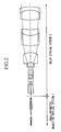
- Fig. 2 is lens layout in which a relay optical system 2 is disposed at the image plane side of the small-diameter objective optical system 1 in Fig. 1 , to make the beam emerging from the object substantially collimated.
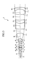
- Fig. 3 shows an example lens diagram of the relay optical system 2
- Table 1 shows example lens data of the relay optical system 2.
- symbol r represents the radius of curvature
- symbol d represents the distance between surfaces
- symbol n d represents the refractive index at the d-line (587.56 nm)
- symbol ⁇ d represents the Abbe number at the d-line (587.56 nm).
- the small-diameter objective optical system 1 With the configuration in Fig. 2 , it is possible to make the small-diameter objective optical system 1 according to this embodiment compatible with infinity-design microscope systems. By designing the system so that the beam diameter on the small-diameter objective optical system side of the relay optical system 2 is small, it is possible to insert the objective optical system of the present invention to a deeper site inside a living organism with minimal invasiveness.
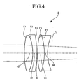
- an image forming lens 3 (focal length, 180) described by the lens data in Table 2, shown in Fig. 4 , is disposed at the image plane side of the relay optical system 2 to provide the image.
- Example 1 of the present invention will now be described using the small-diameter objective optical system shown in Fig. 1 .
- Table 3 is the lens data for the small-diameter objective optical system in Fig. 1 .
- Figs. 5A to 5D are aberration curves for the small-diameter objective optical system in Fig. 1 .
- reference symbol NA indicates the numerical aperture at the object plane, and reference symbol Y indicates the object height.
- the lens diameters of L 1 to L 4 are 0.46 mm, the lens diameter of L 5 to L 8 are 0.6 mm, and the lens diameters of L 9 to L 15 are 0.82 mm; thus the small-diameter objective optical system 1 according to Example 1 is constructed only of lenses with extremely small diameters. Therefore, the small-diameter objective optical system 1 of this Example is suitable for in vivo observation of a region deep inside the body of a small laboratory animal, such as a mouse, over a comparatively long period of time with minimal invasiveness.
- Fig. 6 is a lens diagram of Example 2 of the small-diameter objective lens according to the present invention.
- the small-diameter objective lens 10 according to Example 2 has a longer working distance WD than that of Example 1. Accordingly, it is possible to perform observation without contacting the tip of the lens with the observation target, so as not to physically affect the living organism.
- Table 4 shows the lens data for the small-diameter objective optical system in Fig. 6 .
- Figs. 7A to 7D show aberration curves for the small-diameter objective optical system in Fig. 6 .
- the reference symbols in Figs. 6, 7A to 7D and Table 4 are the same as those in Example 1.
- the lens diameters of L 1 to L 4 are 0.46 mm, the lens diameter of L 5 to L 9 are 0.6 mm, and the lens diameters of L 10 to L 16 are 0.8 mm; thus the small-diameter objective optical system 10 according to this Example is constructed only of lenses with extremely small diameters. Therefore, the small-diameter objective optical system 10 of this Example is suitable for in vivo observation of biological tissue, such as cells and muscle tissue, or various internal organs, such as the heart and liver, and particularly brain tissue, of mammals, including small laboratory animals, over a comparatively long period of time with minimal invasiveness.
- biological tissue such as cells and muscle tissue, or various internal organs, such as the heart and liver, and particularly brain tissue
- Table 5 shows data for conditional expressions (1) to (6) in Example 1 and Example 2.
- Example 1 Example 2 F 1 0.262 0.255 F 3 2.815 2.13 h 1 0.244 0.23 h 3 0.611 0.472 D 1 0.46 0.46 NA 0.465 0.459 R 1 0.4017 0.3821 n 1 1.883 1.883 d 1 1.02 1.06 ⁇ 31 52.32 52.32 ⁇ 32 40.76 40.76 n 31 1.755 1.755 n 32 1.883 1.883 R 3 0.56 0.4931 conditional expressions (1) 0.23 0.246 (2) 0.28 0.29 (3) 2.2 2.3 (4) 11.56 11.56 (5) 0.128 0.128 (6) 5.03 4.32
- the small-diameter objective optical system of the present invention exhibits superior aberrations up to the near-infrared region. Therefore, using near-infrared light, it is possible to observe not only at the skin surface of a specimen, but also inside the body, with comparatively low scattering.
- the small-diameter objective optical system of the present invention can be used in a multiphoton-excitation observation device.
Abstract
Description
- The present invention relates to objective optical systems used in applications such as investigating and imaging of cellular function, and more particularly relates to a small-diameter objective optical system suitable for in vivo examination of animals such as mammals.
This application is based on Japanese Patent Application No.2007-216110 - At present, a method for observing the behavior of molecules in biological cells and tissue labelled with a dye or fluorescent marker with a fluorescence microscope, a confocal laser-scanning microscope or the like is used.
The behavior of molecules in a living mammalian organism, such as a mouse, sometimes differs from that in culture, and therefore, observation of biological tissue and cells is carried out while the specimen is alive (in vivo). (For example, see Japanese Unexamined Patent Application, Publication No.2006-119300 - With conventional microscopes, such as laser-scanning confocal microscopes, it is not assumed that observation of various internal organs of small laboratory animals, such as rats and mice, will be performed in vivo. In examining the interior of a living organism, because the diameter of the objective lens in a conventional microscope is large, it is necessary to perform examination by first making a large incision in the organism. However, making a large incision is highly invasive to the organism, and therefore, it is not possible to carry out observation for a long period of time.
- Furthermore, with the objective optical system in Japanese Unexamined Patent Application, Publication No.
2006-119300 - The present invention has been conceived in light of the circumstances described above, and an object thereof is to provide an objective optical system that can carry out in vivo observation of biological tissue, such as cells and muscle tissue, or various internal organs, such as the heart and liver, and particularly brain tissue, of mammals, including small laboratory animals, over a comparatively long period of time with minimal invasiveness.
- In order to realize the object described above, the present invention provides the following solutions.
The present invention provides a small-diameter objective optical system comprising, in order from an object plane, a first lens group with positive refractive power, including at least one plano-convex lens whose convex surface faces an image plane; a second lens group with positive refractive power, including at least one concave lens; and a third lens group including a cemented lens of which a cemented surface has negative refractive power, wherein the focal length of the third lens group is larger than the focal length of the first lens group. - According to this aspect of the present invention, the first lens group with positive refractive power converts a diverging beam to a substantially collimated beam or to a diverging beam close to a substantially collimated beam.
Also, because it includes the plano-convex lens whose convex surface faces the image plane, it approaches the aplanatic condition, and thus it is possible to suppress spherical aberration and coma produced in this plano-convex lens. - The second lens group with positive refractive power can expand the substantially collimated beam or the divergent beam close to a substantially collimated beam from the first lens group to a substantially collimated beam with a larger diameter.
- The third lens group corrects aberrations such as spherical aberration and coma, as well as chromatic aberration, produced in the first and second lens groups using the cemented surface thereof, which has negative refractive power. Also, by making the focal length of the third lens group larger than the focal length of the first lens group, it is possible to increase the ray height.
- In the aspect of the invention described above, it is preferable that conditional expression (1) below be satisfied:

where - F1 is the focal length of the first lens group,
- F3 is the focal length of the third lens group,
- h1 is a beam diameter of a substantially collimated beam at the first lens group side of the second lens group, and
- h3 is a beam diameter of a substantially collimated beam at the third lens group side of the second lens group.
- If (F1×h3)/(F3×h1) is 0.3 or more, when the focal length F1 of the first lens group is increased, the ray height cannot be decreased. On the other hand, when the focal length F3 of the third lens group is reduced, the ray height of the third lens group cannot be increased, and the various aberrations cannot be corrected with the third lens group. If (F1×h3)/(F3×h1) is 0.2 or less, the focal length F1 of the first lens group is reduced, and it is difficult to correct the spherical aberration.
- In the aspect of the invention described above, it is preferable that conditional expressions (2) and (3) below be satisfied:


where D1 is a smallest lens diameter in the first lens group,
NA is a numerical aperture at the object plane side of the small-diameter objective optical system,
R1 is a smallest radius of curvature in the first lens group,
n1 is a largest refractive index in the first lens group,
d1 is a distance from the object plane to an image plane of a lens at the extreme image plane side in the first lens group. - If (D1×NA)/(R1×n1) is 0.35 or more, the lens diameter D1 increases, making it impossible to realize a small-diameter objective optical system. To decrease the lens diameter D1, the radius of curvature R1 must be reduced; however, when the radius of curvature R1 is reduced, the refractive power of the first lens group is reduced, and spherical aberration is undercorrected. If (D1×NA)/(R1×n1) is 0.25 or less, the NA at the object plane is reduced, or the radius of curvature R1 is increased; therefore the problem of overcorrected spherical aberration occurs.
- If d1/D1 is 2.5 or more, the distance d1 from the object plane to the image plane of the lens at the extreme image plane side in the first lens group increases. Although the amount of spherical aberration is small, the ray height is high. If d1/D1 is 1.5 or less, because d1 is small, the diverging beam must be converted to a substantially collimated beam over a short distance, and the amounts of spherical aberration and coma thus increase.
- In the aspect of the invention described above, it is preferable that conditional expressions (4), (5), and (6) below be satisfied:


where
ν31 is a d-line Abbe number of a lens with a large Abbe number in the cemented lens of the third lens group,
ν32 is a d-line Abbe number of a lens with a small Abbe number in the cemented lens of the third lens group,
n31 is a d-line refractive index of the lens with the large Abbe number in the cemented lens of the third lens group,
n32 is a d-line refractive index of the lens with the small Abbe number in the cemented lens of the third lens group,
F3 is the focal length of the third lens group, and
R3 is a radius of curvature of the cemented surface in the cemented lens of the third lens group. - If |ν31-ν32| is 10 or less, the difference between the Abbe numbers in the cemented lens is small, and it is thus difficult to correct chromatic aberrations.
- If |n31-n32| is 0.12 or less, the radius of curvature of the cemented surface is small, and lens processing becomes difficult. If |n31-n32| is 0.2 or more, the radius of curvature of the cemented surface is large, and correction of spherical aberration and coma becomes difficult.
- If F3/R3 is 4 or less, the focal length F3 of the third lens group is small, and it is thus not possible to reduce the ray height in the third lens group. Alternatively, because the radius of curvature R3 of the cemented surface of the cemented lens in the third lens group is large, a problem occurs in that it is not possible to correct aberrations produced in the first and second lens groups. If F3/R3 is 5.5 or more, the radius of curvature R3 of the cemented surface of the cemented lens in the third lens group is small, and therefore, the problem of overcorrection of spherical aberration and coma occurs.
- According to the present invention, it is possible to carry out in vivo observation of biological tissue, such as cells and muscle tissue, or various internal organs, such as the heart and liver, and particularly brain tissue, of mammals, including small laboratory animals, over a comparatively long period of time with minimal invasiveness.
-
-
Fig. 1 is a lens diagram of a small-diameter objective optical system according to the present invention. -
Fig. 2 is a lens layout in which an infinity-design relay optical system is disposed at an image side of the small-diameter objective optical system inFig. 1 . -
Fig. 3 is a lens diagram of the relay optical system inFig. 2 . -
Fig. 4 is a sectional lens diagram showing an example of an image forming lens disposed at the image side of the infinity-design relay optical system inFig. 2 . -
Fig. 5A is an aberration diagram of the small-diameter objective optical system of Example 1, showing spherical aberration. -
Fig. 5B is an aberration diagram of the small-diameter objective optical system of Example 1, showing the amount of the offense against the sine condition. -
Fig. 5C is an aberration diagram of the small-diameter objective optical system of Example 1, showing astigmatism. -
Fig. 5D is an aberration diagram of the small-diameter objective optical system of Example 1, showing distortion. -
Fig. 6 is a lens diagram according to Example 2 of the small-diameter objective optical system. -
Fig. 7A is an aberration diagram of the small-diameter objective optical system of Example 2, showing spherical aberration. -
Fig. 7B is an aberration diagram of the small-diameter objective optical system of Example 2, showing the amount of the offense against the sine condition. -
Fig. 7C is an aberration diagram of the small-diameter objective optical system of Example 2, showing astigmatism. -
Fig. 7D is an aberration diagram of the small-diameter objective optical system of Example 2, showing distortion. - An embodiment of a small-diameter objective
optical system 1 of the present invention is described below with reference toFig. 1 .
A small-diameter objectiveoptical system 1 according to this embodiment is formed of a first lens group G1, a second lens group G2, and a third lens group G3, disposed in this order from an object plane. - The first lens group G1 is formed of a plano-convex lens L1 whose convex surface faces an image plane and a convex-plano lens L2 whose convex surface faces the object plane. The first lens group G1 has positive refractive power on the whole.
- The second lens group G2 is formed of a cemented lens including a plano-concave lens L3 whose concave surface faces the image plane and a convex-plano lens L4 whose convex surface faces the object plane; a cemented lens including a concave-plano lens L5 whose concave surface faces the object plane and a plano-convex lens L6 whose convex surface faces the image plane; a cemented lens including a plano-convex lens L7 whose convex surface faces the image plane and a concave-plano lens L8 whose concave surface faces the object plane; and a plano-convex lens L9 whose convex surface faces the image plane.
- The third lens group G3 is formed of a cemented lens with negative refractive power, including a plano-concave lens L10 whose concave surface faces the image plane and a convex-plano lens L11 whose convex surface faces the object plane; a convex-plano lens L12 whose convex surface faces the object plane; a cemented lens including a plano-convex lens L13 whose convex surface faces the image plane and a concave-plano lens L14 whose concave surface faces the object plane; and a convex-plano lens L15 whose convex surface faces the object plane.
- In the small-diameter objective optical system in
Fig. 1 , the focal length of the third lens group G3 is larger than the focal length of the first lens group G1. - In this embodiment, the lenses are constructed so as to satisfy conditional expressions (1) to (6) below:


- Here, F1 is the focal length of the first lens group G1, F3 is the focal length of the third lens group G3, h1 is the beam diameter of a substantially collimated light beam at the first lens group side of the second lens group G2, h3 is the beam diameter of a substantially collimated light beam at the third lens group side of the second lens group G2, D1 is the smallest lens diameter in the first lens group G1, NA is the numerical aperture at the object plane side of the small-diameter objective optical system, R1 is the smallest radius of curvature in the first lens group G1, n1 is the largest refractive index in the first lens group G1, d1 is the distance from the object plane to the image plane of the lens at the extreme image plane side of the first lens group G1, ν31 is the d-line Abbe number of the lens with a large Abbe number in the cemented lenses of the third lens group G3, ν32 is the d-line Abbe number of the lens with a small Abbe number in the cemented lenses of the third lens group G3, n31 is the d-line refractive index of the lens with the large Abbe number in the cemented lenses of the third lens group G3, n32 is the d-line refractive index of the lens with the small Abbe number in the cemented lenses of the third lens group G3, and R3 is the radius of curvature of the cemented surface of the cemented lens in the third lens group G3.
- In the first lens group G1, the image-side convex surface of the plano-convex lens L1 can be made close to the aplanatic condition, which makes it possible to reduce the amount of spherical aberration and coma. Additionally, when the overall focal length of the first lens group is reduced, the amounts of spherical aberration and coma of the first lens group become comparatively large on the whole. However, it is possible to convert a divergent beam from the object plane into a substantially collimated beam or a divergent beam that is close to a substantially collimated beam without increasing the ray height, and the thus obtained beam is guided to the second lens group G2.
- The second lens group G2 expands the substantially collimated beam or the divergent beam close to a substantially collimated beam from the first lens group to a substantially collimated beam with an even larger diameter and guides the rays to the third lens group.
- Because the third lens group G3 includes the cemented lens having the cemented surface with negative refractive power, it corrects monochromatic aberrations, including spherical aberration and coma, and chromatic aberrations generated in the first and second lens groups.
Moreover, the ray height is increased by making the focal length F3 of the third lens group G3 larger than the focal length F1 of the first lens group G1. -
Fig. 2 is lens layout in which a relayoptical system 2 is disposed at the image plane side of the small-diameter objectiveoptical system 1 inFig. 1 , to make the beam emerging from the object substantially collimated.Fig. 3 shows an example lens diagram of the relayoptical system 2, and Table 1 shows example lens data of the relayoptical system 2. InFig. 3 and Table 1, symbol r represents the radius of curvature, symbol d represents the distance between surfaces, symbol nd represents the refractive index at the d-line (587.56 nm), and symbol νd represents the Abbe number at the d-line (587.56 nm). -
[Table 1] r d nd νd OBJECT PLANE 1 ∞ 4.67 1.7725 49.6 2 ∞ 1 3 2.385 2 1.43875 94.93 4 ∞ 0.2 5 ∞ 1.73 1.43875 94.93 6 -1.462 2.34 1.6779 55.34 7 ∞ 1.7 8 -2.339 2.23 1.43875 94.93 9 -2.339 5.17 1.7725 49.6 10 -6.021 3.63 11 24.102 5.16 1.51633 64.14 12 6.202 3 1.6779 55.34 13 15.002 5 14 16.326 5 1.43875 94.93 15 -7.205 1.7 1.7725 49.6 16 -16.508 IMAGE PLANE - With the configuration in
Fig. 2 , it is possible to make the small-diameter objectiveoptical system 1 according to this embodiment compatible with infinity-design microscope systems. By designing the system so that the beam diameter on the small-diameter objective optical system side of the relayoptical system 2 is small, it is possible to insert the objective optical system of the present invention to a deeper site inside a living organism with minimal invasiveness. - When the relay
optical system 2 is disposed at the image plane side of the small-diameter objectiveoptical system 1, as shown inFig. 2 , the light emitted towards the image plane side of the relayoptical system 2 is collimated and thus does not form an image. Therefore, an image forming lens 3 (focal length, 180) described by the lens data in Table 2, shown inFig. 4 , is disposed at the image plane side of the relayoptical system 2 to provide the image. -
[Table 2] r d nd νd OBJECT PLANE 1 68.7541 7.7321 1.48749 70.21 2 -37.5679 3.4742 1.8061 40.95 3 -102.8477 0.6973 4 84.3099 6.0238 1.834 37.17 5 -50.71 3.0298 1.6445 40.82 6 40.6619 IMAGE PLANE - Example 1 of the present invention will now be described using the small-diameter objective optical system shown in
Fig. 1 . Table 3 is the lens data for the small-diameter objective optical system inFig. 1 .Figs. 5A to 5D are aberration curves for the small-diameter objective optical system inFig. 1 . InFigs. 5A to 5D , reference symbol NA indicates the numerical aperture at the object plane, and reference symbol Y indicates the object height. -
[Table 3] r d nd νd OBJECT PLANE ∞ 0.02
(working distance)1.33304
(water)55.79 1 ∞ 0.44 1.883 40.76 2 -0.4017 0.01 3 0.5346 0.55 1.883 40.76 4 ∞ 0.03 5 ∞ 0.61 1.48749 70.23 6 0.4786 0.44 1.883 40.76 7 ∞ 0.3 8 -0.4933 0.5 1.755 52.32 9 ∞ 0.51 1.48749 70.23 10 -0.5591 0.02 11 ∞ 0.53 1.755 52.32 12 -0.9021 0.36 1.48749 70.23 13 ∞ 4.09 14 ∞ 0.75 1.48749 70.23 15 -1.4212 0.03 16 ∞ 0.78 1.883 40.76 17 0.5625 0.63 1.755 52.32 18 ∞ 0.03 19 1.0076 0.71 1.48749 70.23 20 ∞ 0.03 21 ∞ 0.63 1.755 52.32 22 -0.5598 0.78 1.883 40.76 23 ∞ 0.59 24 1.4267 0.75 1.48749 70.23 25 ∞ 0.92 - The lens diameters of L1 to L4 are 0.46 mm, the lens diameter of L5 to L8 are 0.6 mm, and the lens diameters of L9 to L15 are 0.82 mm; thus the small-diameter objective
optical system 1 according to Example 1 is constructed only of lenses with extremely small diameters.
Therefore, the small-diameter objectiveoptical system 1 of this Example is suitable for in vivo observation of a region deep inside the body of a small laboratory animal, such as a mouse, over a comparatively long period of time with minimal invasiveness. -
Fig. 6 is a lens diagram of Example 2 of the small-diameter objective lens according to the present invention. The small-diameter objective lens 10 according to Example 2 has a longer working distance WD than that of Example 1. Accordingly, it is possible to perform observation without contacting the tip of the lens with the observation target, so as not to physically affect the living organism.
Table 4 shows the lens data for the small-diameter objective optical system inFig. 6 .Figs. 7A to 7D show aberration curves for the small-diameter objective optical system inFig. 6 . The reference symbols inFigs. 6, 7A to 7D and Table 4 are the same as those in Example 1. -
[Table 4] r d nd νd OBJECT PLANE ∞ 0.05
(working distance)1.33304
(water)55.79 1 ∞ 0.4 1.883 40.76 2 -0.3821 0.01 3 0.534 0.6 1.883 40.76 4 ∞ 0.04 5 ∞ 0.61 1.48749 70.23 6 0.998 0.6 1.883 40.76 7 ∞ 0.1 8 -0.4761 0.51 1.48749 70.23 9 ∞ 0.5 1.755 52.32 10 -1.1993 0.02 11 0.7012 0.51 1.48749 70.23 12 ∞ 0.5 1.755 52.32 13 -0.7257 0.05 14 -0.4761 0.45 1.883 40.76 15 ∞ 2.5 16 1.2859 0.8 1.48749 70.23 17 ∞ 2.07 18 ∞ 0.65 1.883 40.76 19 0.4931 0.71 1.755 52.32 20 ∞ 0.03 21 1.147 0.8 1.48749 70.23 22 ∞ 0.03 23 ∞ 0.71 1.755 52.32 24 -0.4931 0.65 1.883 40.76 25 ∞ 0.42 26 0.9151 0.7 1.48749 70.23 27 ∞ 1.76 - The lens diameters of L1 to L4 are 0.46 mm, the lens diameter of L5 to L9 are 0.6 mm, and the lens diameters of L10 to L16 are 0.8 mm; thus the small-diameter objective
optical system 10 according to this Example is constructed only of lenses with extremely small diameters.
Therefore, the small-diameter objectiveoptical system 10 of this Example is suitable for in vivo observation of biological tissue, such as cells and muscle tissue, or various internal organs, such as the heart and liver, and particularly brain tissue, of mammals, including small laboratory animals, over a comparatively long period of time with minimal invasiveness. - Table 5 shows data for conditional expressions (1) to (6) in Example 1 and Example 2.
-
[Table 5] Example 1 Example 2 F1 0.262 0.255 F3 2.815 2.13 h1 0.244 0.23 h3 0.611 0.472 D1 0.46 0.46 NA 0.465 0.459 R1 0.4017 0.3821 n1 1.883 1.883 d1 1.02 1.06 ν31 52.32 52.32 ν32 40.76 40.76 n31 1.755 1.755 n32 1.883 1.883 R3 0.56 0.4931 conditional expressions (1) 0.23 0.246 (2) 0.28 0.29 (3) 2.2 2.3 (4) 11.56 11.56 (5) 0.128 0.128 (6) 5.03 4.32 - The small-diameter objective optical system of the present invention exhibits superior aberrations up to the near-infrared region. Therefore, using near-infrared light, it is possible to observe not only at the skin surface of a specimen, but also inside the body, with comparatively low scattering. In addition, the small-diameter objective optical system of the present invention can be used in a multiphoton-excitation observation device.
Claims (4)
- A small-diameter objective optical system comprising, in order from an object plane:a first lens group with positive refractive power, including at least one plano-convex lens whose convex surface faces an image plane;a second lens group with positive refractive power, including at least one concave lens; anda third lens group including a cemented lens of which a cemented surface has negative refractive power,wherein the focal length of the third lens group is larger than the focal length of the first lens group.
- A small-diameter objective optical system according to Claim 1, satisfying conditional expression (1) below:

whereF1 is the focal length of the first lens group,F3 is the focal length of the third lens group,h1 is a beam diameter of a substantially collimated beam at the first lens group side of the second lens group, andh3 is a beam diameter of a substantially collimated beam at the third lens group side of the second lens group. - A small-diameter objective optical system according to Claim 1, satisfying conditional expressions (2) and (3) below:


whereD1 is a smallest lens diameter in the first lens group,NA is a numerical aperture at the object plane side of the small-diameter objective optical system,R1 is a smallest radius of curvature in the first lens group,n1 is a largest refractive index in the first lens group,d1 is a distance from the object plane to an image plane of a lens at the extreme image plane side in the first lens group. - A small-diameter objective optical system according to Claim 1, satisfying conditional expressions (4), (5), and (6) below:


whereν31 is a d-line Abbe number of a lens with a large Abbe number in the cemented lens of the third lens group,ν32 is a d-line Abbe number of a lens with a small Abbe number in the cemented lens of the third lens group,n31 is a d-line refractive index of the lens with the large Abbe number in the cemented lens of the third lens group,n32 is a d-line refractive index of the lens with the small Abbe number in the cemented lens of the third lens group,F3 is the focal length of the third lens group, andR3 is a radius of curvature of the cemented surface in the cemented lens of the third lens group.
Applications Claiming Priority (1)
| Application Number | Priority Date | Filing Date | Title |
|---|---|---|---|
| JP2007216110A JP5185578B2 (en) | 2007-08-22 | 2007-08-22 | Small-diameter objective optical system |
Publications (3)
| Publication Number | Publication Date |
|---|---|
| EP2028519A2 true EP2028519A2 (en) | 2009-02-25 |
| EP2028519A3 EP2028519A3 (en) | 2009-08-19 |
| EP2028519B1 EP2028519B1 (en) | 2013-08-28 |
Family
ID=40098288
Family Applications (1)
| Application Number | Title | Priority Date | Filing Date |
|---|---|---|---|
| EP08012390.4A Expired - Fee Related EP2028519B1 (en) | 2007-08-22 | 2008-07-09 | Small-diameter objective optical system |
Country Status (3)
| Country | Link |
|---|---|
| US (1) | US7733583B2 (en) |
| EP (1) | EP2028519B1 (en) |
| JP (1) | JP5185578B2 (en) |
Cited By (5)
| Publication number | Priority date | Publication date | Assignee | Title |
|---|---|---|---|---|
| JP2016519341A (en) * | 2013-05-15 | 2016-06-30 | ノバダック テクノロジーズ インコーポレイテッド | High compensation relay system |
| US9968244B2 (en) | 2000-07-14 | 2018-05-15 | Novadaq Technologies ULC | Compact fluorescence endoscopy video system |
| US10016119B2 (en) | 2014-09-01 | 2018-07-10 | Olympus Corporation | Objective optical system |
| US10182709B2 (en) | 2002-01-15 | 2019-01-22 | Novadaq Technologies ULC | Filter for use with imaging endoscopes |
| US10293122B2 (en) | 2016-03-17 | 2019-05-21 | Novadaq Technologies ULC | Endoluminal introducer with contamination avoidance |
Families Citing this family (9)
| Publication number | Priority date | Publication date | Assignee | Title |
|---|---|---|---|---|
| WO2007106624A2 (en) | 2006-02-07 | 2007-09-20 | Novadaq Technologies Inc. | Near infrared imaging |
| JP5449947B2 (en) * | 2009-09-25 | 2014-03-19 | オリンパス株式会社 | Objective optical system |
| JP6218475B2 (en) * | 2013-07-23 | 2017-10-25 | オリンパス株式会社 | Objective optical system |
| CN108474926B (en) * | 2016-01-06 | 2020-09-29 | 奥林巴斯株式会社 | Objective optical system |
| JP6807818B2 (en) | 2017-09-27 | 2021-01-06 | 富士フイルム株式会社 | Objective optical system for endoscopes and endoscopes |
| JP6877309B2 (en) | 2017-09-27 | 2021-05-26 | 富士フイルム株式会社 | Objective optical system for endoscopes and endoscopes |
| JP6800824B2 (en) * | 2017-09-27 | 2020-12-16 | 富士フイルム株式会社 | Objective optical system for endoscopes and endoscopes |
| US10953797B2 (en) * | 2018-04-05 | 2021-03-23 | Toyota Motor Engineering & Manufacturing North America, Inc. | Cloaking devices with converging lenses and coherent image guides and vehicles comprising the same |
| CN115452783B (en) * | 2022-08-22 | 2023-12-22 | 深圳赛陆医疗科技有限公司 | Detection device and gene sequencer |
Citations (2)
| Publication number | Priority date | Publication date | Assignee | Title |
|---|---|---|---|---|
| JP2006119300A (en) | 2004-10-20 | 2006-05-11 | Olympus Corp | Liquid immersion objective optical system |
| JP2007216110A (en) | 2006-02-15 | 2007-08-30 | Mitsubishi Chemicals Corp | Adsorbing element and humidity conditioning air conditioner |
Family Cites Families (7)
| Publication number | Priority date | Publication date | Assignee | Title |
|---|---|---|---|---|
| JPS63314512A (en) * | 1987-06-17 | 1988-12-22 | Fuotonikusu:Kk | Objective lens for optical fiber sensor for non-contact type optical measurement |
| JP3044588B2 (en) * | 1992-04-20 | 2000-05-22 | オリンパス光学工業株式会社 | Objective lens for endoscope |
| JPH0854561A (en) * | 1994-08-09 | 1996-02-27 | Fuji Photo Optical Co Ltd | Objective lens for angle-of-visual-field variable endoscope |
| JPH10260362A (en) * | 1997-03-19 | 1998-09-29 | Olympus Optical Co Ltd | Liquid-dip type objective |
| JP2005309412A (en) * | 2004-03-25 | 2005-11-04 | Olympus Corp | Laser scanning type microscope |
| JP2006084825A (en) * | 2004-09-16 | 2006-03-30 | Olympus Corp | Microscopic system |
| JP4727252B2 (en) * | 2005-02-17 | 2011-07-20 | オリンパス株式会社 | Small objective optical system |
-
2007
- 2007-08-22 JP JP2007216110A patent/JP5185578B2/en not_active Expired - Fee Related
-
2008
- 2008-07-09 EP EP08012390.4A patent/EP2028519B1/en not_active Expired - Fee Related
- 2008-07-18 US US12/175,960 patent/US7733583B2/en active Active
Patent Citations (2)
| Publication number | Priority date | Publication date | Assignee | Title |
|---|---|---|---|---|
| JP2006119300A (en) | 2004-10-20 | 2006-05-11 | Olympus Corp | Liquid immersion objective optical system |
| JP2007216110A (en) | 2006-02-15 | 2007-08-30 | Mitsubishi Chemicals Corp | Adsorbing element and humidity conditioning air conditioner |
Cited By (5)
| Publication number | Priority date | Publication date | Assignee | Title |
|---|---|---|---|---|
| US9968244B2 (en) | 2000-07-14 | 2018-05-15 | Novadaq Technologies ULC | Compact fluorescence endoscopy video system |
| US10182709B2 (en) | 2002-01-15 | 2019-01-22 | Novadaq Technologies ULC | Filter for use with imaging endoscopes |
| JP2016519341A (en) * | 2013-05-15 | 2016-06-30 | ノバダック テクノロジーズ インコーポレイテッド | High compensation relay system |
| US10016119B2 (en) | 2014-09-01 | 2018-07-10 | Olympus Corporation | Objective optical system |
| US10293122B2 (en) | 2016-03-17 | 2019-05-21 | Novadaq Technologies ULC | Endoluminal introducer with contamination avoidance |
Also Published As
| Publication number | Publication date |
|---|---|
| EP2028519A3 (en) | 2009-08-19 |
| JP2009048085A (en) | 2009-03-05 |
| US20090052062A1 (en) | 2009-02-26 |
| EP2028519B1 (en) | 2013-08-28 |
| US7733583B2 (en) | 2010-06-08 |
| JP5185578B2 (en) | 2013-04-17 |
Similar Documents
| Publication | Publication Date | Title |
|---|---|---|
| EP2028519B1 (en) | Small-diameter objective optical system | |
| US8107170B2 (en) | Objective optical system | |
| US7215478B1 (en) | Immersion objective optical system | |
| US7046450B2 (en) | Liquid-immersion objective optical system | |
| US7304789B2 (en) | Microscope system and objective unit | |
| US7177088B2 (en) | Compact objective optical system and examination apparatus | |
| EP3205253A1 (en) | Endoscope | |
| JP4504153B2 (en) | Immersion objective optical system | |
| JP2010134218A (en) | Microscope objective lens | |
| US20130331653A1 (en) | Microscope apparatus, method and application | |
| JP4457666B2 (en) | Microscope objective lens | |
| EP3557302A1 (en) | Dry objective | |
| US10324269B2 (en) | Immersion objective | |
| JP5449947B2 (en) | Objective optical system | |
| JP4744123B2 (en) | Infinity designed objective optical system and infinity optical unit | |
| US10859808B2 (en) | Microscope objective | |
| US11782253B2 (en) | Objective lens, optical system, and microscope | |
| JP5281873B2 (en) | Immersion objective optical system with an intermediate imaging plane and designed at infinity | |
| JP2010224477A (en) | Microscope objective lens | |
| EP3557303A1 (en) | Microscope objective | |
| EP3557304A1 (en) | Microscope objective | |
| JP2009198955A (en) | Relay optical system | |
| JP2009037060A (en) | Liquid immersion microscope objective lens | |
| EP3557305A1 (en) | Immersion microscope objective | |
| JP2010014856A (en) | Microscope objective lens |
Legal Events
| Date | Code | Title | Description |
|---|---|---|---|
| PUAI | Public reference made under article 153(3) epc to a published international application that has entered the european phase |
Free format text: ORIGINAL CODE: 0009012 |
|
| AK | Designated contracting states |
Kind code of ref document: A2 Designated state(s): AT BE BG CH CY CZ DE DK EE ES FI FR GB GR HR HU IE IS IT LI LT LU LV MC MT NL NO PL PT RO SE SI SK TR |
|
| AX | Request for extension of the european patent |
Extension state: AL BA MK RS |
|
| PUAL | Search report despatched |
Free format text: ORIGINAL CODE: 0009013 |
|
| AK | Designated contracting states |
Kind code of ref document: A3 Designated state(s): AT BE BG CH CY CZ DE DK EE ES FI FR GB GR HR HU IE IS IT LI LT LU LV MC MT NL NO PL PT RO SE SI SK TR |
|
| AX | Request for extension of the european patent |
Extension state: AL BA MK RS |
|
| RIC1 | Information provided on ipc code assigned before grant |
Ipc: G02B 23/24 20060101ALI20090710BHEP Ipc: G02B 21/02 20060101AFI20081217BHEP |
|
| 17P | Request for examination filed |
Effective date: 20091123 |
|
| 17Q | First examination report despatched |
Effective date: 20100113 |
|
| AKX | Designation fees paid |
Designated state(s): DE GB |
|
| GRAP | Despatch of communication of intention to grant a patent |
Free format text: ORIGINAL CODE: EPIDOSNIGR1 |
|
| GRAS | Grant fee paid |
Free format text: ORIGINAL CODE: EPIDOSNIGR3 |
|
| GRAA | (expected) grant |
Free format text: ORIGINAL CODE: 0009210 |
|
| AK | Designated contracting states |
Kind code of ref document: B1 Designated state(s): DE GB |
|
| REG | Reference to a national code |
Ref country code: GB Ref legal event code: FG4D |
|
| REG | Reference to a national code |
Ref country code: DE Ref legal event code: R096 Ref document number: 602008027116 Country of ref document: DE Effective date: 20131024 |
|
| REG | Reference to a national code |
Ref country code: DE Ref legal event code: R097 Ref document number: 602008027116 Country of ref document: DE |
|
| PLBE | No opposition filed within time limit |
Free format text: ORIGINAL CODE: 0009261 |
|
| STAA | Information on the status of an ep patent application or granted ep patent |
Free format text: STATUS: NO OPPOSITION FILED WITHIN TIME LIMIT |
|
| 26N | No opposition filed |
Effective date: 20140530 |
|
| REG | Reference to a national code |
Ref country code: DE Ref legal event code: R097 Ref document number: 602008027116 Country of ref document: DE Effective date: 20140530 |
|
| GBPC | Gb: european patent ceased through non-payment of renewal fee |
Effective date: 20140709 |
|
| PG25 | Lapsed in a contracting state [announced via postgrant information from national office to epo] |
Ref country code: GB Free format text: LAPSE BECAUSE OF NON-PAYMENT OF DUE FEES Effective date: 20140709 |
|
| PGFP | Annual fee paid to national office [announced via postgrant information from national office to epo] |
Ref country code: DE Payment date: 20190719 Year of fee payment: 12 |
|
| REG | Reference to a national code |
Ref country code: DE Ref legal event code: R119 Ref document number: 602008027116 Country of ref document: DE |
|
| PG25 | Lapsed in a contracting state [announced via postgrant information from national office to epo] |
Ref country code: DE Free format text: LAPSE BECAUSE OF NON-PAYMENT OF DUE FEES Effective date: 20210202 |