EP2028452A1 - Capteur d'angle à codage multitour - Google Patents
Capteur d'angle à codage multitour Download PDFInfo
- Publication number
- EP2028452A1 EP2028452A1 EP07360038A EP07360038A EP2028452A1 EP 2028452 A1 EP2028452 A1 EP 2028452A1 EP 07360038 A EP07360038 A EP 07360038A EP 07360038 A EP07360038 A EP 07360038A EP 2028452 A1 EP2028452 A1 EP 2028452A1
- Authority
- EP
- European Patent Office
- Prior art keywords
- light guide
- angle sensor
- photodetector
- sensor according
- cells
- Prior art date
- Legal status (The legal status is an assumption and is not a legal conclusion. Google has not performed a legal analysis and makes no representation as to the accuracy of the status listed.)
- Granted
Links
Images

Classifications
-
- G—PHYSICS
- G01—MEASURING; TESTING
- G01D—MEASURING NOT SPECIALLY ADAPTED FOR A SPECIFIC VARIABLE; ARRANGEMENTS FOR MEASURING TWO OR MORE VARIABLES NOT COVERED IN A SINGLE OTHER SUBCLASS; TARIFF METERING APPARATUS; MEASURING OR TESTING NOT OTHERWISE PROVIDED FOR
- G01D5/00—Mechanical means for transferring the output of a sensing member; Means for converting the output of a sensing member to another variable where the form or nature of the sensing member does not constrain the means for converting; Transducers not specially adapted for a specific variable
- G01D5/26—Mechanical means for transferring the output of a sensing member; Means for converting the output of a sensing member to another variable where the form or nature of the sensing member does not constrain the means for converting; Transducers not specially adapted for a specific variable characterised by optical transfer means, i.e. using infrared, visible, or ultraviolet light
- G01D5/32—Mechanical means for transferring the output of a sensing member; Means for converting the output of a sensing member to another variable where the form or nature of the sensing member does not constrain the means for converting; Transducers not specially adapted for a specific variable characterised by optical transfer means, i.e. using infrared, visible, or ultraviolet light with attenuation or whole or partial obturation of beams of light
- G01D5/34—Mechanical means for transferring the output of a sensing member; Means for converting the output of a sensing member to another variable where the form or nature of the sensing member does not constrain the means for converting; Transducers not specially adapted for a specific variable characterised by optical transfer means, i.e. using infrared, visible, or ultraviolet light with attenuation or whole or partial obturation of beams of light the beams of light being detected by photocells
- G01D5/347—Mechanical means for transferring the output of a sensing member; Means for converting the output of a sensing member to another variable where the form or nature of the sensing member does not constrain the means for converting; Transducers not specially adapted for a specific variable characterised by optical transfer means, i.e. using infrared, visible, or ultraviolet light with attenuation or whole or partial obturation of beams of light the beams of light being detected by photocells using displacement encoding scales
- G01D5/34707—Scales; Discs, e.g. fixation, fabrication, compensation
- G01D5/34715—Scale reading or illumination devices
- G01D5/34723—Scale reading or illumination devices involving light-guides
-
- G—PHYSICS
- G01—MEASURING; TESTING
- G01D—MEASURING NOT SPECIALLY ADAPTED FOR A SPECIFIC VARIABLE; ARRANGEMENTS FOR MEASURING TWO OR MORE VARIABLES NOT COVERED IN A SINGLE OTHER SUBCLASS; TARIFF METERING APPARATUS; MEASURING OR TESTING NOT OTHERWISE PROVIDED FOR
- G01D5/00—Mechanical means for transferring the output of a sensing member; Means for converting the output of a sensing member to another variable where the form or nature of the sensing member does not constrain the means for converting; Transducers not specially adapted for a specific variable
- G01D5/26—Mechanical means for transferring the output of a sensing member; Means for converting the output of a sensing member to another variable where the form or nature of the sensing member does not constrain the means for converting; Transducers not specially adapted for a specific variable characterised by optical transfer means, i.e. using infrared, visible, or ultraviolet light
- G01D5/32—Mechanical means for transferring the output of a sensing member; Means for converting the output of a sensing member to another variable where the form or nature of the sensing member does not constrain the means for converting; Transducers not specially adapted for a specific variable characterised by optical transfer means, i.e. using infrared, visible, or ultraviolet light with attenuation or whole or partial obturation of beams of light
- G01D5/34—Mechanical means for transferring the output of a sensing member; Means for converting the output of a sensing member to another variable where the form or nature of the sensing member does not constrain the means for converting; Transducers not specially adapted for a specific variable characterised by optical transfer means, i.e. using infrared, visible, or ultraviolet light with attenuation or whole or partial obturation of beams of light the beams of light being detected by photocells
- G01D5/347—Mechanical means for transferring the output of a sensing member; Means for converting the output of a sensing member to another variable where the form or nature of the sensing member does not constrain the means for converting; Transducers not specially adapted for a specific variable characterised by optical transfer means, i.e. using infrared, visible, or ultraviolet light with attenuation or whole or partial obturation of beams of light the beams of light being detected by photocells using displacement encoding scales
- G01D5/34776—Absolute encoders with analogue or digital scales
-
- G—PHYSICS
- G01—MEASURING; TESTING
- G01D—MEASURING NOT SPECIALLY ADAPTED FOR A SPECIFIC VARIABLE; ARRANGEMENTS FOR MEASURING TWO OR MORE VARIABLES NOT COVERED IN A SINGLE OTHER SUBCLASS; TARIFF METERING APPARATUS; MEASURING OR TESTING NOT OTHERWISE PROVIDED FOR
- G01D2205/00—Indexing scheme relating to details of means for transferring or converting the output of a sensing member
- G01D2205/20—Detecting rotary movement
- G01D2205/22—Detecting rotary movement by converting the rotary movement into a linear movement
-
- G—PHYSICS
- G01—MEASURING; TESTING
- G01D—MEASURING NOT SPECIALLY ADAPTED FOR A SPECIFIC VARIABLE; ARRANGEMENTS FOR MEASURING TWO OR MORE VARIABLES NOT COVERED IN A SINGLE OTHER SUBCLASS; TARIFF METERING APPARATUS; MEASURING OR TESTING NOT OTHERWISE PROVIDED FOR
- G01D2205/00—Indexing scheme relating to details of means for transferring or converting the output of a sensing member
- G01D2205/20—Detecting rotary movement
- G01D2205/26—Details of encoders or position sensors specially adapted to detect rotation beyond a full turn of 360°, e.g. multi-rotation
Definitions
- the present invention relates to an angle sensor comprising a rotating disc integral with a rotary shaft supporting angular encoding means.
- One possible application which serves as a guide for the present description, is the steering column of a motor vehicle.
- the steering column of a motor vehicle in addition to coding the position of the disc on a lathe, it is necessary to know absolutely what is the position of the steering wheel on several laps (a steering column must turn about 5 laps).
- most current angular sensors provide an absolute coding of the angular position on a turn, and it remains to encode the turn in which one is located.
- Incremental counting of turns is not enough, because the exact position of the steering wheel must be identified precisely even at startup.
- optical solutions based on shading technology for example the solutions disclosed in the document DE-198 55 064 .
- These describe configurations in which the light source is radially disposed on one side of the rotating disk, a photodetector being arranged parallel to the other side of the disk.
- a moving cursor in a radial direction relative to the disc blocks or filters the passage of the light beam from the light source to perform the coding of the lathe.
- a blocking or filtering element of the light beam, directly integrated in the rotating disk, also allows the coding of the angular position on a lathe.
- the same photodetector is used to process the displacement of two light signals respectively encoding the lathe and the angular position.
- the angle sensor of the present invention also comprising a rotating disk, is provided with an annular surface divided into coding cells of the angular position of the disk, said cells transforming an incident light beam into a light optical signal conveying a code said angular position, said signal then being led by a light guide to a fixed photodetector connected to processing means of said code.
- the light guide is movable in rotation along an axis parallel to the axis of rotation of the disc, an arm integral with said guide, driven in a direction of radial progression by the rotating disc, moving the light guide relative to the photodetector.
- the signal conveying the optical code corresponding to the angular position of the rotating disc also moves relative to the photodetector. It is the positioning of the signal relative to the photodetector which is used to determine the turn in which one is located.
- the photodetector does not detect two types of light signals corresponding to the coding respectively of the angular position and the tower, but a single light signal whose position relative to the detector is changing. according to the turn.
- the disc may comprise a spiral groove on n turns, guiding a finger fitted to the free end of the arm secured to the light guide.
- the groove develops in a spiral of about 5 turns.
- the finger guided by the spiral groove moves substantially radially relative to the disk, and rotates said light guide.
- the axis of rotation of the guide is placed near the edge of the disc, and contiguous to the entrance of the light guide.
- the arm is also secured to the light guide at its inlet, but on the opposite side to the axis of rotation. This arm actually acts as an actuating lever communicating its movement to the light guide.
- This may for example have a rectilinear portion portion oriented substantially tangentially to the disc.
- the light guide may consist of two respectively input and output light baffles connected by a rectilinear portion giving the light signal an inverted U-shaped path.
- the incident light beam is converted into an optical signal conveying a code of the angular position, which is then led to the fixed photodetector, in this case placed outside the disk substantially at the same level as the disk.
- the pivot of the rotation of the light guide and the photodetector are placed on the same plate.
- the prior art shows configurations in which the components are placed on either side of the disk, increasing the bulk of the volume under the steering wheel necessary for the installation of a steering column angle sensor.
- the pivot of the rotation of the light guide and the electronic component constituting the photodetector are arranged substantially at the same level, substantially reducing the thickness of the angle sensor module.
- the coding cells comprise computer-generated holograms, diffracting the light beam consisting of a laser beam into a digital optical code.
- Cells with computer-generated holograms are easy to manufacture by injection or pressing onto a plastic disc according to a well-controlled industrial process.
- the laser beam illuminates a cell with a computer-generated hologram, it generates a unique diffraction pattern consisting of illuminated or dark spots, constituting a digital optical code. This binary code indicates a precise angular position of the rotating disk.
- the photodetector consists of a row of photodetection cells.
- it is a conventional electronic component with tabs weldable on a printed circuit.
- the computer-generated holograms constituting the coding cells placed on the rotating disks are provided such that the diffracted signal constitutes a binary code consisting of illuminated or dark spots which are aligned.
- the light guide then conducts the row of spots constituting this code towards the photodetector such that the axis of the photodetection cells and that of the row of spots is substantially parallel.
- the processing means then perform a coding of the lathe by determining the positioning of the optical code conveyed by the optical signal relative to the photodetector.
- the coding of the turn depends on the position of the excited cells inside the row of cells constituting the photodetector.
- a rotary disc (1) secured in the application example used to a steering column (not shown), has on its upper surface spiral grooves (5) guiding a finger (6) disposed at the end of an arm (7) secured to a light guide (8) free to rotate about a pivot (9).
- This light guide (8) consists of prisms (2, 3) respectively input (2) and output (3) connected by a rectilinear portion (10).
- a peripheral annular surface (11) of the rotating disc (1) is provided with coding cells for the angular position of the disc.
- These cells diffract an incident laser beam.
- the diffracted light signal is then passed through the light guide (8) to a photodetector component (4) having photodetection cells aligned in a row.
- the diffracted signal consisting of illuminated and dark spots, is conveyed by the light guide (8) to the photodetector (4).
- the holograms are calculated so that the diffracted signal has line spots, generated in a substantially radial direction relative to the rotating disk (1), so that the row of spots restored by the output prism (3) of the light guide (8) is parallel to the row of the photodetection cells of the component (4).
- the finger (6) is approximately in the middle, that is to say in the third round since it is considered that a steering column must perform about 5 turns.
- the diffracted light conveying the binary code encoding the angular position of the disk (1) is substantially in the middle of the photodetector (4).
- the encoding of the lathe is therefore simply by recognition by the processing system of the zone in which the diffractive code is located.
- a preliminary calibration makes it possible to know exactly, according to the illuminated photodetection cells, in which turn one is. It is then possible to simply code, in addition to the angular position by the diffractive code obtained, the turn by the position of this code on the line of photodetection cells.
Landscapes
- Physics & Mathematics (AREA)
- General Physics & Mathematics (AREA)
- Optical Transform (AREA)
- Length Measuring Devices By Optical Means (AREA)
- Measurement Of Length, Angles, Or The Like Using Electric Or Magnetic Means (AREA)
- Transmission And Conversion Of Sensor Element Output (AREA)
Abstract
Description
- La présente invention concerne un capteur d'angle comportant un disque rotatif solidaire d'un arbre tournant support de moyens de codage angulaires.
- Une application possible, qui sert de fil conducteur à la présente description, est la colonne de direction d'un véhicule automobile. Dans une telle application, outre le codage de la position du disque sur un tour, il est nécessaire de savoir de manière absolue quelle est la position du volant sur plusieurs tours (une colonne de direction doit tourner d'environ 5 tours). Or, la plupart des capteurs angulaires actuels ne fournissent un codage absolu de la position angulaire que sur un tour, et il reste donc à coder le tour dans lequel on se situe.
- Un comptage incrémental des tours n'est pas suffisant, car la position précise du volant doit être identifiée précisément même au démarrage.
- Nombre de solutions utilisées actuellement sont basées sur des technologies magnétiques, par exemple des capteurs à effet Hall associés à des solutions mécaniques à engrenages. Les roues dentées sont alors excentrées par rapport à la colonne de direction, et il faut veiller à concevoir un système d'encombrement le plus réduit possible, car le volume sous volant disponible est en général peu important.
- Il existe également des solutions optiques basées sur la technologie des ombrages, comme par exemple les solutions divulguées dans le document
DE-198 55 064 . Celles-ci décrivent des configurations dans lesquelles la source de lumière est disposée radialement d'un côté du disque rotatif, un photodétecteur étant disposé parallèlement de l'autre côté du disque. Un curseur mobile dans une direction radiale relativement au disque bloque ou filtre le passage du rayon lumineux issu de la source de lumière en vue d'effectuer le codage du tour. Un élément de blocage ou de filtration du faisceau lumineux, directement intégré au disque rotatif, permet par ailleurs le codage de la position angulaire sur un tour. Le même photodétecteur est donc utilisé pour traiter le déplacement de deux signaux lumineux codant respectivement le tour et la position angulaire. - Dans deux des trois solutions montrées, le système permettant le déplacement radial du curseur n'est pas expliqué. Dans le troisième cas, il s'agit d'un cavalier guidé en rotation par une piste en relief spiralée, et maintenu en translation radiale par un dispositif détecteur rectiligne et de très faible largeur, qui ne s'apparente pas aux configurations de photodétecteurs classiques disponibles dans le commerce. Les solutions proposées apparaissent donc théoriques.
- Le capteur d'angle de la présente invention, comportant également un disque rotatif, est doté d'une surface annulaire divisée en cellules de codage de la position angulaire du disque, lesdites cellules transformant un faisceau lumineux incident en un signal optique lumineux véhiculant un code de ladite position angulaire, ledit signal étant ensuite conduit par un guide de lumière vers un photodétecteur fixe relié à des moyens de traitement dudit code.
- Selon une caractéristique essentielle de l'invention, le guide de lumière est mobile en rotation selon un axe parallèle à l'axe de rotation du disque, un bras solidaire dudit guide, entraîné dans une direction d'allure radiale par le disque en rotation, déplaçant le guide de lumière relativement au photodétecteur.
- En d'autres termes, le signal véhiculant le code optique correspondant à la position angulaire du disque rotatif se déplace également par rapport au photodétecteur. C'est le positionnement du signal relativement au photodétecteur qui est utilisé pour déterminer le tour dans lequel on se situe. Ainsi, à l'inverse des solutions de l'art antérieur, le photodétecteur ne détecte pas deux types de signaux lumineux correspondant au codage respectivement de la position angulaire et du tour, mais un seul signal lumineux, dont la position par rapport au détecteur évolue selon le tour.
- Selon une possibilité, le disque peut comporter un sillon spiralé sur n tours, guidant un doigt équipant l'extrémité libre du bras solidaire du guide de lumière. Dans l'exemple de la colonne de direction, le sillon se développe selon une spirale d'environ 5 tours.
- Compte tenu que le guide de lumière n'a qu'un degré de liberté, en rotation, le doigt guidé par le sillon spiralé se déplace sensiblement radialement par rapport au disque, et fait pivoter ledit guide de lumière.
- De préférence, l'axe de rotation du guide est placé au voisinage de la bordure du disque, et contigu à l'entrée du guide de lumière.
- De préférence encore, le bras est aussi solidarisé au guide de lumière au niveau de son entrée, mais du côté opposé à l'axe de rotation. Ce bras agit en fait comme un levier d'actionnement communiquant son mouvement au guide de lumière.
- Celui-ci peut par exemple présenter une portion d'allure rectiligne s'orientant sensiblement tangentiellement au disque.
- Plus précisément, le guide de lumière peut être constitué de deux déflecteurs de lumière respectivement d'entrée et de sortie reliés par une portion rectiligne conférant au signal lumineux un trajet en U inversé.
- Le faisceau lumineux incident est transformé en signal optique véhiculant un code de la position angulaire, lequel est alors conduit vers le photodétecteur fixe, en l'espèce placé à l'extérieur du disque sensiblement au même niveau que le disque.
- D'ailleurs, de préférence, le pivot de la rotation du guide de lumière et le photodétecteur sont placés sur une même platine.
- L'art antérieur montre des configurations dans lesquelles les composants sont placés de part et d'autre du disque, augmentant l'encombrement du volume sous volant nécessaire à l'installation d'un capteur d'angle de colonne de direction. Dans l'invention, le pivot de la rotation du guide de lumière et le composant électronique constituant le photodétecteur sont disposés pratiquement au même niveau, permettant de réduire sensiblement l'épaisseur du module capteur d'angle.
- De préférence, selon l'invention, les cellules de codage comportent des hologrammes générés par ordinateur, diffractant le faisceau lumineux constitué d'un faisceau laser en un code optique numérique.
- Des cellules dotées d'hologrammes générés par ordinateur sont faciles à fabriquer par injection ou pressage sur un disque en plastique selon un procédé industriel bien maîtrisé. Lorsque le faisceau laser illumine une cellule dotée d'un hologramme généré par ordinateur, il génère une figure de diffraction unique constituée de taches illuminées ou sombres, constituant un code optique numérique. Ce code binaire indique une position angulaire précise du disque rotatif.
- Selon une possibilité, le photodétecteur consiste en une rangée de cellules de photodétection. En pratique, il s'agit d'un composant électronique classique à pattes soudables sur un circuit imprimé.
- Dans cette hypothèse, les hologrammes générés par ordinateur constituant les cellules de codage placées sur les disques rotatifs sont prévus de telle sorte que le signal diffracté constitue un code binaire formé de taches lumineuses ou sombres qui sont alignées. Le guide de lumière conduit alors la rangée de taches constituant ce code vers le photodétecteur de telle sorte que l'axe des cellules de photodétection et celui de la rangée de taches soit sensiblement parallèles.
- Les moyens de traitement, selon l'invention, effectuent alors un codage du tour par détermination du positionnement du code optique véhiculé par le signal optique relativement au photodétecteur.
- En d'autres termes, le codage du tour dépend de la position des cellules excitées à l'intérieur de la rangée de cellules constituant le photodétecteur.
- Il faut alors prévoir un photodétecteur constitué d'un nombre suffisant de cellules de photodétection pour permettre la lecture du déplacement des codes numériques obtenus par diffraction le long de la rangée des cellules de photodétection, et adapter le déplacement du système mécanique - en l'occurrence le guide de lumière rotatif - à la longueur du photodétecteur.
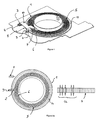
- L'invention va être à présent décrite plus en détail, en référence aux figures, pour lesquelles :
- la
figure 1 montre, en vue perspective partielle, la configuration adoptée pour le capteur d'angle de l'invention ; et - les
figures 2a à 2c représentent schématiquement le fonctionnement du dispositif, en montrant le déplacement du code optique numérique par rapport au photodétecteur en fonction du tour parcouru par le capteur d'angle. - En référence à la
figure 1 , un disque rotatif (1), solidarisé dans l'exemple d'application utilisé à une colonne de direction (non représentée), comporte sur sa surface supérieure des sillons spiralés (5) guidant un doigt (6) disposé à l'extrémité d'un bras (7) solidaire d'un guide de lumière (8) libre en rotation autour d'un pivot (9). Ce guide de lumière (8) est constitué de prismes (2, 3) respectivement d'entrée (2) et de sortie (3) reliés par une portion d'allure rectiligne (10). Une surface annulaire périphérique (11) du disque rotatif (1) est dotée de cellules de codage de la position angulaire du disque. - Ces cellules, comportant en l'espèce des hologrammes générés par ordinateur, diffractent un rayon laser incident. Le signal lumineux diffracté est ensuite conduit, par le guide de lumière (8), vers un composant photodétecteur (4) comportant des cellules de photodétection alignées en une rangée. Le signal diffracté, composé de taches illuminées et sombres, est véhiculé par le guide de lumière (8) vers le photodétecteur (4). Les hologrammes sont calculés de telle sorte que le signal diffracté comporte des taches en lignes, générées dans une direction sensiblement radiale par rapport au disque rotatif (1), de telle sorte que la rangée de taches restituée par le prisme de sortie (3) du guide de lumière (8) est d'allure parallèle à la rangée des cellules de photodétection du composant (4).
- Lorsque la colonne de direction tourne, entraînant le disque rotatif (1), le doigt (6) se déplace dans une direction sensiblement radiale, faisant pivoter par l'intermédiaire du bras (7) le guide de lumière (8) autour du pivot (9). C'est ce qui apparaît dans les
figures 2a à 2c . Ainsi, en référence à lafigure 2a , le doigt (6) se trouve dans le premier tour de rotation, le prisme de sortie (3) du photodétecteur est positionné vers l'une des extrémités du composant photodétecteur (4), et le code lumineux numérique obtenu après diffraction est guidé vers l'une des extrémités de la ligne de cellules de photodétection. - En
figure 2b , le doigt (6) se trouve à peu près au milieu, c'est-à-dire dans le troisième tour puisqu'on considère qu'une colonne de direction doit effectuer environ 5 tours. Dans ce cas, la lumière diffractée véhiculant le code binaire codant la position angulaire du disque (1) se trouve sensiblement au milieu du photodétecteur (4). - Enfin, en
figure 2c , on se trouve dans le tour (5), et le code binaire est alors déporté vers l'autre extrémité de la ligne de cellules de photodétection. - Le codage du tour se fait donc simplement par reconnaissance par le système de traitement de la zone dans laquelle se situe le code diffractif. Un calibrage préliminaire permet de savoir exactement, en fonction des cellules de photodétection illuminées, dans quel tour on se trouve. Il est alors possible de coder simplement, outre la position angulaire par le code diffractif obtenu, le tour par la position de ce code sur la ligne de cellules de photodétection.
Claims (11)
- Capteur d'angle comportant un disque rotatif (1) doté d'une surface annulaire (11) divisée en cellules de codage de la position angulaire du disque (1), lesdites cellules transformant un faisceau lumineux incident en un signal optique lumineux véhiculant un code de ladite position angulaire, ledit signal étant conduit par un guide de lumière (8) vers un photodétecteur (4) fixe relié à des moyens de traitement dudit code,
caractérisé en ce que le guide de lumière (8) est mobile en rotation selon un axe parallèle à l'axe de rotation du disque (1), un bras (7) solidaire dudit guide (8), entraîné dans une direction d'allure radiale par le disque (1) en rotation, déplaçant le guide de lumière (8) relativement au photodétecteur (4). - Capteur d'angle selon la revendication précédente, caractérisé en ce que le disque (1) comporte un sillon spiralé (5) sur n tours, guidant un doigt (6) équipant l'extrémité libre du bras (7) solidaire du guide de lumière (8).
- Capteur d'angle selon l'une des revendications précédentes,
caractérisé en ce que l'axe de rotation du guide de lumière (8) est placé au voisinage de la bordure du disque (1), et contigu à l'entrée du guide de lumière (8). - Capteur d'angle selon la revendication précédente, caractérisé en ce que le bras (7) est solidarisé au guide de lumière (8) au niveau de son entrée, du côté opposé à l'axe de rotation.
- Capteur d'angle selon l'une quelconque des revendications précédentes, caractérisé en ce que le guide de lumière (8) présente une portion (10) d'allure rectiligne s'orientant sensiblement tangentiellement au disque (1).
- Capteur d'angle selon l'une quelconque des revendications précédentes, caractérisé en ce que le guide de lumière (8) est constitué de deux déflecteurs (2, 3) de lumière respectivement d'entrée (2) et de sortie (3) reliés par une portion rectiligne (10) conférant au signal lumineux un trajet en U inversé.
- Capteur d'angle selon l'une quelconque des revendications précédentes, caractérisé en ce que le pivot (9) de la rotation du guide de lumière (8) et le photodétecteur (4) sont placés sur une même platine.
- Capteur d'angle selon l'une quelconque des revendications précédentes, caractérisé en ce que les cellules de codage comportent des hologrammes générés par ordinateur, diffractant le faisceau lumineux constitué d'un faisceau laser en un code optique numérique.
- Capteur d'angle selon l'une quelconque des revendications précédentes, caractérisé en ce que le photodétecteur (4) consiste en une rangée de cellules de photodétection.
- Capteur d'angle selon l'une des revendications précédentes,
caractérisé en ce que les moyens de traitement effectuent un codage du tour par détermination du code optique véhiculé par le signal optique relativement au photodétecteur (4). - Capteur d'angle selon les revendications 9 et 10, caractérisé en ce que le codage du tour dépend de la position des cellules excitées à l'intérieur de la rangée de cellules constituant le photodétecteur (4).
Priority Applications (4)
| Application Number | Priority Date | Filing Date | Title |
|---|---|---|---|
| DE602007006792T DE602007006792D1 (de) | 2007-08-23 | 2007-08-23 | Winkelsensor mit Multiturn-Kodierung |
| AT07360038T ATE469341T1 (de) | 2007-08-23 | 2007-08-23 | Winkelsensor mit multiturn-kodierung |
| EP07360038A EP2028452B1 (fr) | 2007-08-23 | 2007-08-23 | Capteur d'angle à codage multitour |
| US12/229,298 US20090055849A1 (en) | 2007-08-23 | 2008-08-21 | Angle sensor with multi-turn encoding |
Applications Claiming Priority (1)
| Application Number | Priority Date | Filing Date | Title |
|---|---|---|---|
| EP07360038A EP2028452B1 (fr) | 2007-08-23 | 2007-08-23 | Capteur d'angle à codage multitour |
Publications (2)
| Publication Number | Publication Date |
|---|---|
| EP2028452A1 true EP2028452A1 (fr) | 2009-02-25 |
| EP2028452B1 EP2028452B1 (fr) | 2010-05-26 |
Family
ID=39027599
Family Applications (1)
| Application Number | Title | Priority Date | Filing Date |
|---|---|---|---|
| EP07360038A Not-in-force EP2028452B1 (fr) | 2007-08-23 | 2007-08-23 | Capteur d'angle à codage multitour |
Country Status (4)
| Country | Link |
|---|---|
| US (1) | US20090055849A1 (fr) |
| EP (1) | EP2028452B1 (fr) |
| AT (1) | ATE469341T1 (fr) |
| DE (1) | DE602007006792D1 (fr) |
Families Citing this family (1)
| Publication number | Priority date | Publication date | Assignee | Title |
|---|---|---|---|---|
| US9513103B2 (en) * | 2011-04-19 | 2016-12-06 | Ford Global Technologies, Llc | Hitch angle sensor assembly |
Citations (3)
| Publication number | Priority date | Publication date | Assignee | Title |
|---|---|---|---|---|
| DE19638911A1 (de) * | 1996-09-23 | 1998-03-26 | Teves Gmbh Alfred | Drehwinkelsensor mit integrierter Umdrehungserkennung |
| DE19855064A1 (de) * | 1998-11-28 | 2000-05-31 | Kostal Leopold Gmbh & Co Kg | Lenkwinkelsensor |
| FR2798193A1 (fr) * | 1999-09-06 | 2001-03-09 | Pwb Ruhlatec Ind Prod Gmbh | Procede d'acquisition multiple de signaux optoelectroniques et dispositif pour la mise en oeuvre du procede |
Family Cites Families (5)
| Publication number | Priority date | Publication date | Assignee | Title |
|---|---|---|---|---|
| US3235672A (en) * | 1961-11-17 | 1966-02-15 | American Optical Corp | Optical sound recording and reproduction |
| US3980811A (en) * | 1974-09-03 | 1976-09-14 | Nihon Denshi Kabushiki Kaisha | Contacting pickup optical reproduction system |
| DE19835972C1 (de) * | 1998-08-08 | 2000-01-20 | Kostal Leopold Gmbh & Co Kg | Optoelektronische Positionserfassungseinrichtung zur absoluten Weg- oder Winkelbestimmung sowie Verwendung einer solchen Einrichtung |
| DE19942322A1 (de) * | 1999-09-06 | 2001-03-08 | Pwb Ruhlatec Ind Prod Gmbh | Untersetzungsgetriebe für Dreh- und Schwenkbewegungen |
| US7348543B2 (en) * | 2003-01-16 | 2008-03-25 | Yaskawa Eshed Technologies Ltd. | Optical encoder with hollow light guide for indicating the angular position of a rotary shaft |
-
2007
- 2007-08-23 DE DE602007006792T patent/DE602007006792D1/de active Active
- 2007-08-23 AT AT07360038T patent/ATE469341T1/de not_active IP Right Cessation
- 2007-08-23 EP EP07360038A patent/EP2028452B1/fr not_active Not-in-force
-
2008
- 2008-08-21 US US12/229,298 patent/US20090055849A1/en not_active Abandoned
Patent Citations (3)
| Publication number | Priority date | Publication date | Assignee | Title |
|---|---|---|---|---|
| DE19638911A1 (de) * | 1996-09-23 | 1998-03-26 | Teves Gmbh Alfred | Drehwinkelsensor mit integrierter Umdrehungserkennung |
| DE19855064A1 (de) * | 1998-11-28 | 2000-05-31 | Kostal Leopold Gmbh & Co Kg | Lenkwinkelsensor |
| FR2798193A1 (fr) * | 1999-09-06 | 2001-03-09 | Pwb Ruhlatec Ind Prod Gmbh | Procede d'acquisition multiple de signaux optoelectroniques et dispositif pour la mise en oeuvre du procede |
Also Published As
| Publication number | Publication date |
|---|---|
| ATE469341T1 (de) | 2010-06-15 |
| DE602007006792D1 (de) | 2010-07-08 |
| US20090055849A1 (en) | 2009-02-26 |
| EP2028452B1 (fr) | 2010-05-26 |
Similar Documents
| Publication | Publication Date | Title |
|---|---|---|
| EP0484194B1 (fr) | Capteur d'angle de rotation | |
| EP2452160B1 (fr) | Capteur de position absolue et multi-périodique | |
| FR2987113A1 (fr) | Dispositif de capteur pour detecter l'angle de rotation d'un composant tournant equipant un vehicule | |
| FR2919385A1 (fr) | Capteur magnetique sans contact de position absolue multitour a arbre traversant | |
| FR2653507A1 (fr) | Dispositif d'accouplement synchrone d'elements tournants d'une machine, notamment une machine d'impression. | |
| FR2987114A1 (fr) | Dispositif de detection de l'angle de rotation d'un composant tournant | |
| FR2987116A1 (fr) | Dispositif de capteur pour detecter les angles de rotation d'un composant rotatif d'un vehicule | |
| EP2028452B1 (fr) | Capteur d'angle à codage multitour | |
| EP1677081B1 (fr) | Procédé de détermination de la position d'un premier élément en mouvement relativement à un second élément et dispositif pour mettre en oeuvre ledit procédé | |
| WO2015114256A1 (fr) | Détermination d'une position de référence angulaire de direction assistée à partir de fronts montants et descendants d'un signal d'index | |
| EP1862771B1 (fr) | Codeur angulaire optique avec detection du faux-rond | |
| FR2828278A1 (fr) | Capteur de deplacement angulaire et son application dans une direction assistee pour vehicule automobile | |
| EP1862774B1 (fr) | Optical multiturn rotational encoder | |
| CH639191A5 (fr) | Dispositif pour definir une position de reference d'une piece mobile en translation. | |
| FR2798193A1 (fr) | Procede d'acquisition multiple de signaux optoelectroniques et dispositif pour la mise en oeuvre du procede | |
| FR2732285A1 (fr) | Contacteur electrique tournant comprenant des moyens de detrompage au montage | |
| FR2783483A1 (fr) | Systeme a capteur d'angle, notamment pour colonne de direction de vehicule automobile | |
| FR2764058A1 (fr) | Dispositif de detection pour colonne de direction | |
| EP0983929B1 (fr) | Capteur d'angle absolue entrainé par une couronne liée au volant | |
| EP4522998A1 (fr) | Tachymetre pour roue d'aeronef | |
| EP0475809B1 (fr) | Capteur de vitesse d'un élément rotatif notamment d'une roue de véhicule automobile | |
| WO2024160947A1 (fr) | Actionneur électromécanique | |
| EP1452762A2 (fr) | Mécanisme de transformation d'un mouvement de rotation en translation, et dispositif d'embrayage l'utilisant. | |
| WO2017006050A1 (fr) | Dispositif de detection d'une position neutre d'une commande de vitesses d'une boite de vitesses d'un vehicule automobile | |
| EP2388557B1 (fr) | Capteur optique de position angulaire absolue utilisant la technique de la polarimétrie |
Legal Events
| Date | Code | Title | Description |
|---|---|---|---|
| PUAI | Public reference made under article 153(3) epc to a published international application that has entered the european phase |
Free format text: ORIGINAL CODE: 0009012 |
|
| 17P | Request for examination filed |
Effective date: 20070830 |
|
| AK | Designated contracting states |
Kind code of ref document: A1 Designated state(s): AT BE BG CH CY CZ DE DK EE ES FI FR GB GR HU IE IS IT LI LT LU LV MC MT NL PL PT RO SE SI SK TR |
|
| AX | Request for extension of the european patent |
Extension state: AL BA HR MK RS |
|
| 17Q | First examination report despatched |
Effective date: 20090813 |
|
| AKX | Designation fees paid |
Designated state(s): AT BE BG CH CY CZ DE DK EE ES FI FR GB GR HU IE IS IT LI LT LU LV MC MT NL PL PT RO SE SI SK TR |
|
| GRAP | Despatch of communication of intention to grant a patent |
Free format text: ORIGINAL CODE: EPIDOSNIGR1 |
|
| GRAS | Grant fee paid |
Free format text: ORIGINAL CODE: EPIDOSNIGR3 |
|
| GRAA | (expected) grant |
Free format text: ORIGINAL CODE: 0009210 |
|
| AK | Designated contracting states |
Kind code of ref document: B1 Designated state(s): AT BE BG CH CY CZ DE DK EE ES FI FR GB GR HU IE IS IT LI LT LU LV MC MT NL PL PT RO SE SI SK TR |
|
| REG | Reference to a national code |
Ref country code: GB Ref legal event code: FG4D Free format text: NOT ENGLISH |
|
| REG | Reference to a national code |
Ref country code: CH Ref legal event code: EP |
|
| REG | Reference to a national code |
Ref country code: IE Ref legal event code: FG4D Free format text: LANGUAGE OF EP DOCUMENT: FRENCH |
|
| REF | Corresponds to: |
Ref document number: 602007006792 Country of ref document: DE Date of ref document: 20100708 Kind code of ref document: P |
|
| REG | Reference to a national code |
Ref country code: NL Ref legal event code: VDEP Effective date: 20100526 |
|
| LTIE | Lt: invalidation of european patent or patent extension |
Effective date: 20100526 |
|
| PG25 | Lapsed in a contracting state [announced via postgrant information from national office to epo] |
Ref country code: SE Free format text: LAPSE BECAUSE OF FAILURE TO SUBMIT A TRANSLATION OF THE DESCRIPTION OR TO PAY THE FEE WITHIN THE PRESCRIBED TIME-LIMIT Effective date: 20100526 Ref country code: LT Free format text: LAPSE BECAUSE OF FAILURE TO SUBMIT A TRANSLATION OF THE DESCRIPTION OR TO PAY THE FEE WITHIN THE PRESCRIBED TIME-LIMIT Effective date: 20100526 |
|
| PG25 | Lapsed in a contracting state [announced via postgrant information from national office to epo] |
Ref country code: IS Free format text: LAPSE BECAUSE OF FAILURE TO SUBMIT A TRANSLATION OF THE DESCRIPTION OR TO PAY THE FEE WITHIN THE PRESCRIBED TIME-LIMIT Effective date: 20100926 Ref country code: AT Free format text: LAPSE BECAUSE OF FAILURE TO SUBMIT A TRANSLATION OF THE DESCRIPTION OR TO PAY THE FEE WITHIN THE PRESCRIBED TIME-LIMIT Effective date: 20100526 Ref country code: SI Free format text: LAPSE BECAUSE OF FAILURE TO SUBMIT A TRANSLATION OF THE DESCRIPTION OR TO PAY THE FEE WITHIN THE PRESCRIBED TIME-LIMIT Effective date: 20100526 Ref country code: LV Free format text: LAPSE BECAUSE OF FAILURE TO SUBMIT A TRANSLATION OF THE DESCRIPTION OR TO PAY THE FEE WITHIN THE PRESCRIBED TIME-LIMIT Effective date: 20100526 Ref country code: FI Free format text: LAPSE BECAUSE OF FAILURE TO SUBMIT A TRANSLATION OF THE DESCRIPTION OR TO PAY THE FEE WITHIN THE PRESCRIBED TIME-LIMIT Effective date: 20100526 |
|
| PG25 | Lapsed in a contracting state [announced via postgrant information from national office to epo] |
Ref country code: CY Free format text: LAPSE BECAUSE OF FAILURE TO SUBMIT A TRANSLATION OF THE DESCRIPTION OR TO PAY THE FEE WITHIN THE PRESCRIBED TIME-LIMIT Effective date: 20100609 Ref country code: PL Free format text: LAPSE BECAUSE OF FAILURE TO SUBMIT A TRANSLATION OF THE DESCRIPTION OR TO PAY THE FEE WITHIN THE PRESCRIBED TIME-LIMIT Effective date: 20100526 |
|
| REG | Reference to a national code |
Ref country code: IE Ref legal event code: FD4D |
|
| PG25 | Lapsed in a contracting state [announced via postgrant information from national office to epo] |
Ref country code: NL Free format text: LAPSE BECAUSE OF FAILURE TO SUBMIT A TRANSLATION OF THE DESCRIPTION OR TO PAY THE FEE WITHIN THE PRESCRIBED TIME-LIMIT Effective date: 20100526 Ref country code: DK Free format text: LAPSE BECAUSE OF FAILURE TO SUBMIT A TRANSLATION OF THE DESCRIPTION OR TO PAY THE FEE WITHIN THE PRESCRIBED TIME-LIMIT Effective date: 20100526 Ref country code: EE Free format text: LAPSE BECAUSE OF FAILURE TO SUBMIT A TRANSLATION OF THE DESCRIPTION OR TO PAY THE FEE WITHIN THE PRESCRIBED TIME-LIMIT Effective date: 20100526 Ref country code: IE Free format text: LAPSE BECAUSE OF FAILURE TO SUBMIT A TRANSLATION OF THE DESCRIPTION OR TO PAY THE FEE WITHIN THE PRESCRIBED TIME-LIMIT Effective date: 20100526 Ref country code: PT Free format text: LAPSE BECAUSE OF FAILURE TO SUBMIT A TRANSLATION OF THE DESCRIPTION OR TO PAY THE FEE WITHIN THE PRESCRIBED TIME-LIMIT Effective date: 20100927 |
|
| BERE | Be: lapsed |
Owner name: DELPHI TECHNOLOGIES, INC. Effective date: 20100831 |
|
| PG25 | Lapsed in a contracting state [announced via postgrant information from national office to epo] |
Ref country code: RO Free format text: LAPSE BECAUSE OF FAILURE TO SUBMIT A TRANSLATION OF THE DESCRIPTION OR TO PAY THE FEE WITHIN THE PRESCRIBED TIME-LIMIT Effective date: 20100526 Ref country code: SK Free format text: LAPSE BECAUSE OF FAILURE TO SUBMIT A TRANSLATION OF THE DESCRIPTION OR TO PAY THE FEE WITHIN THE PRESCRIBED TIME-LIMIT Effective date: 20100526 Ref country code: CZ Free format text: LAPSE BECAUSE OF FAILURE TO SUBMIT A TRANSLATION OF THE DESCRIPTION OR TO PAY THE FEE WITHIN THE PRESCRIBED TIME-LIMIT Effective date: 20100526 |
|
| PG25 | Lapsed in a contracting state [announced via postgrant information from national office to epo] |
Ref country code: MC Free format text: LAPSE BECAUSE OF NON-PAYMENT OF DUE FEES Effective date: 20100831 Ref country code: IT Free format text: LAPSE BECAUSE OF FAILURE TO SUBMIT A TRANSLATION OF THE DESCRIPTION OR TO PAY THE FEE WITHIN THE PRESCRIBED TIME-LIMIT Effective date: 20100526 |
|
| PLBE | No opposition filed within time limit |
Free format text: ORIGINAL CODE: 0009261 |
|
| STAA | Information on the status of an ep patent application or granted ep patent |
Free format text: STATUS: NO OPPOSITION FILED WITHIN TIME LIMIT |
|
| PG25 | Lapsed in a contracting state [announced via postgrant information from national office to epo] |
Ref country code: GR Free format text: LAPSE BECAUSE OF FAILURE TO SUBMIT A TRANSLATION OF THE DESCRIPTION OR TO PAY THE FEE WITHIN THE PRESCRIBED TIME-LIMIT Effective date: 20100827 |
|
| 26N | No opposition filed |
Effective date: 20110301 |
|
| REG | Reference to a national code |
Ref country code: DE Ref legal event code: R097 Ref document number: 602007006792 Country of ref document: DE Effective date: 20110228 |
|
| PG25 | Lapsed in a contracting state [announced via postgrant information from national office to epo] |
Ref country code: BE Free format text: LAPSE BECAUSE OF NON-PAYMENT OF DUE FEES Effective date: 20100831 |
|
| PG25 | Lapsed in a contracting state [announced via postgrant information from national office to epo] |
Ref country code: MT Free format text: LAPSE BECAUSE OF FAILURE TO SUBMIT A TRANSLATION OF THE DESCRIPTION OR TO PAY THE FEE WITHIN THE PRESCRIBED TIME-LIMIT Effective date: 20100526 |
|
| REG | Reference to a national code |
Ref country code: CH Ref legal event code: PL |
|
| GBPC | Gb: european patent ceased through non-payment of renewal fee |
Effective date: 20110823 |
|
| PG25 | Lapsed in a contracting state [announced via postgrant information from national office to epo] |
Ref country code: CH Free format text: LAPSE BECAUSE OF NON-PAYMENT OF DUE FEES Effective date: 20110831 Ref country code: LI Free format text: LAPSE BECAUSE OF NON-PAYMENT OF DUE FEES Effective date: 20110831 |
|
| PG25 | Lapsed in a contracting state [announced via postgrant information from national office to epo] |
Ref country code: GB Free format text: LAPSE BECAUSE OF NON-PAYMENT OF DUE FEES Effective date: 20110823 |
|
| PG25 | Lapsed in a contracting state [announced via postgrant information from national office to epo] |
Ref country code: BG Free format text: LAPSE BECAUSE OF FAILURE TO SUBMIT A TRANSLATION OF THE DESCRIPTION OR TO PAY THE FEE WITHIN THE PRESCRIBED TIME-LIMIT Effective date: 20100526 Ref country code: HU Free format text: LAPSE BECAUSE OF FAILURE TO SUBMIT A TRANSLATION OF THE DESCRIPTION OR TO PAY THE FEE WITHIN THE PRESCRIBED TIME-LIMIT Effective date: 20101127 Ref country code: LU Free format text: LAPSE BECAUSE OF NON-PAYMENT OF DUE FEES Effective date: 20100823 |
|
| PG25 | Lapsed in a contracting state [announced via postgrant information from national office to epo] |
Ref country code: TR Free format text: LAPSE BECAUSE OF FAILURE TO SUBMIT A TRANSLATION OF THE DESCRIPTION OR TO PAY THE FEE WITHIN THE PRESCRIBED TIME-LIMIT Effective date: 20100526 |
|
| PG25 | Lapsed in a contracting state [announced via postgrant information from national office to epo] |
Ref country code: BG Free format text: LAPSE BECAUSE OF FAILURE TO SUBMIT A TRANSLATION OF THE DESCRIPTION OR TO PAY THE FEE WITHIN THE PRESCRIBED TIME-LIMIT Effective date: 20100826 |
|
| PG25 | Lapsed in a contracting state [announced via postgrant information from national office to epo] |
Ref country code: ES Free format text: LAPSE BECAUSE OF FAILURE TO SUBMIT A TRANSLATION OF THE DESCRIPTION OR TO PAY THE FEE WITHIN THE PRESCRIBED TIME-LIMIT Effective date: 20100906 |
|
| REG | Reference to a national code |
Ref country code: FR Ref legal event code: PLFP Year of fee payment: 9 |
|
| REG | Reference to a national code |
Ref country code: FR Ref legal event code: PLFP Year of fee payment: 10 |
|
| REG | Reference to a national code |
Ref country code: FR Ref legal event code: PLFP Year of fee payment: 11 |
|
| REG | Reference to a national code |
Ref country code: FR Ref legal event code: PLFP Year of fee payment: 12 |
|
| REG | Reference to a national code |
Ref country code: DE Ref legal event code: R082 Ref document number: 602007006792 Country of ref document: DE Representative=s name: MANITZ FINSTERWALD PATENT- UND RECHTSANWALTSPA, DE Ref country code: DE Ref legal event code: R082 Ref document number: 602007006792 Country of ref document: DE Representative=s name: MANITZ FINSTERWALD PATENTANWAELTE PARTMBB, DE Ref country code: DE Ref legal event code: R081 Ref document number: 602007006792 Country of ref document: DE Owner name: APTIV TECHNOLOGIES LIMITED, BB Free format text: FORMER OWNER: DELPHI TECHNOLOGIES, INC., TROY, MICH., US |
|
| PGFP | Annual fee paid to national office [announced via postgrant information from national office to epo] |
Ref country code: FR Payment date: 20190826 Year of fee payment: 13 |
|
| PG25 | Lapsed in a contracting state [announced via postgrant information from national office to epo] |
Ref country code: FR Free format text: LAPSE BECAUSE OF NON-PAYMENT OF DUE FEES Effective date: 20200831 |
|
| P01 | Opt-out of the competence of the unified patent court (upc) registered |
Effective date: 20230425 |
|
| PGFP | Annual fee paid to national office [announced via postgrant information from national office to epo] |
Ref country code: DE Payment date: 20240827 Year of fee payment: 18 |
|
| REG | Reference to a national code |
Ref country code: DE Ref legal event code: R081 Ref document number: 602007006792 Country of ref document: DE Owner name: APTIV TECHNOLOGIES AG, CH Free format text: FORMER OWNER: APTIV TECHNOLOGIES LIMITED, ST. MICHAEL, BB |
|
| REG | Reference to a national code |
Ref country code: DE Ref legal event code: R119 Ref document number: 602007006792 Country of ref document: DE |