EP2028121A2 - Bouchon de bouteille extensible - Google Patents
Bouchon de bouteille extensible Download PDFInfo
- Publication number
- EP2028121A2 EP2028121A2 EP08013655A EP08013655A EP2028121A2 EP 2028121 A2 EP2028121 A2 EP 2028121A2 EP 08013655 A EP08013655 A EP 08013655A EP 08013655 A EP08013655 A EP 08013655A EP 2028121 A2 EP2028121 A2 EP 2028121A2
- Authority
- EP
- European Patent Office
- Prior art keywords
- resilient member
- bottle stopper
- shank
- movable member
- disc
- Prior art date
- Legal status (The legal status is an assumption and is not a legal conclusion. Google has not performed a legal analysis and makes no representation as to the accuracy of the status listed.)
- Withdrawn
Links
Images


Classifications
-
- B—PERFORMING OPERATIONS; TRANSPORTING
- B65—CONVEYING; PACKING; STORING; HANDLING THIN OR FILAMENTARY MATERIAL
- B65D—CONTAINERS FOR STORAGE OR TRANSPORT OF ARTICLES OR MATERIALS, e.g. BAGS, BARRELS, BOTTLES, BOXES, CANS, CARTONS, CRATES, DRUMS, JARS, TANKS, HOPPERS, FORWARDING CONTAINERS; ACCESSORIES, CLOSURES, OR FITTINGS THEREFOR; PACKAGING ELEMENTS; PACKAGES
- B65D39/00—Closures arranged within necks or pouring openings or in discharge apertures, e.g. stoppers
- B65D39/12—Closures arranged within necks or pouring openings or in discharge apertures, e.g. stoppers expansible, e.g. inflatable
-
- B—PERFORMING OPERATIONS; TRANSPORTING
- B65—CONVEYING; PACKING; STORING; HANDLING THIN OR FILAMENTARY MATERIAL
- B65D—CONTAINERS FOR STORAGE OR TRANSPORT OF ARTICLES OR MATERIALS, e.g. BAGS, BARRELS, BOTTLES, BOXES, CANS, CARTONS, CRATES, DRUMS, JARS, TANKS, HOPPERS, FORWARDING CONTAINERS; ACCESSORIES, CLOSURES, OR FITTINGS THEREFOR; PACKAGING ELEMENTS; PACKAGES
- B65D55/00—Accessories for container closures not otherwise provided for
- B65D55/02—Locking devices; Means for discouraging or indicating unauthorised opening or removal of closure
- B65D55/026—Locking devices; Means for discouraging or indicating unauthorised opening or removal of closure initial opening or unauthorised access being indicated by a visual change using indicators other than tearable means, e.g. change of colour, pattern or opacity
Definitions
- the present invention relates to a bottle stopper and, more particularly, to a bottle stopper for a liquid container, which is expansible in a radial direction for sealing the liquid container and shrinkable in the said direction for opening.
- Liquids such as vinegar, oil, whiskey, wine, etc are packaged in containers such as bottles or urns made of glass or potter clay.
- a liquid is injected into the container, and a stopper is inserted into the mouth of the container to seal the container.
- the outer diameter of the stopper is slightly larger than the inner diameter of the mouth of the container to assure sealing between the inner wall of the mouth of the container and the outer periphery of the stopper mounted in the mouth. Therefore, the stopper is able to resist high pressure inside the container and thereby preserves the liquid in the container.
- Taiwan Patent Publication No. 467850 to Applicants discloses a bottle stopper including a pressing member that is pressed axially downward to force an expansible portion of a body to expand radially outward when using the bottle stopper to seal a bottle.
- the expansible portion of the body causes radial expansion of a peripheral wall of a resilient member to tightly press against and seal the bottle.
- the resilient member is made of elastomeric material to replace corks that are liable to break when opening the bottle.
- the peripheral wall of the resilient member can radially expand by downward movement of a shank of the pressing member and the expansible portion of the body, the bottle stopper has too many elements to cut the costs thereof.
- the extent of radial expansion of the bottle stopper is limited, which is particularly true for bottles made by blowing glass materials. Further, bottles made by blowing have small protrusions or recesses in the inner wall of the neck such that precise control of the inner diameter of the neck is impossible while leakage problems arise. Further, the body of the bottle stopper includes only four petals such that the resilient member has substantially square cross sections when the petals expand radially, failing to provide efficient sealing to the inner wall of the mouth of the bottle.
- Another type of conventional bottle stopper disclosed in TW Utility Model No. 327412 includes a pin, and around which a resilient member, a block, a washer, and a cap are stacked in sequence.
- a lever 60 is pivotally mounted to an outer face of the cap. When the lever is bent downward, a bottom of the pin is moved upward to press against and cause radial expansion of the resilient member. Thus, the length of the resilient member is compressed to produce larger radial expansion to thereby enhance sealing reliability.
- currently available automatic bottle-sealing machines cannot proceed with pivotal movement for moving the lever but perform axial downward movement. Further, the lever on the cap prevents the cap from combining with various ornamental caps for different bottles.
- An adjustable type of conventional bottle stopper disclosed in TW Utility Model No. 409703 includes a knob, a resilient member, and an adjusting rod.
- a threaded groove is defined in a bottom of the knob whereas the adjusting rod includes outer threading on a top thereof.
- the bottle stopper has no means for retaining it in an appropriate threaded locking state.
- the primary object of the present invention is to provide an expansible bottle stopper including a body, a resilient member, and a movable member that is longitudinally movable relative to the body.
- the resilient member By a first-stage longitudinal displacement of the movable member relative to the body, the resilient member is caused to expand radially to tightly attach to an inner wall of a mouth of a container. Long-term preservation of liquid in the container can be attained without the risk of quality degrading.
- the secondary object of the present invention is to provide an expansible bottle stopper including a body, a resilient member, and a movable member that is longitudinally movable relative to the body.
- a further object of the present invention is to provide an expansible bottle stopper including a body, a resilient member, and a movable member that is longitudinally movable relative to the body.
- the resilient member is caused to shrink radially to allow the bottle stopper to be easily removed from the mouth of the container, thereby allowing liquid in the container to be poured out.
- the appearance of the bottle stopper is perceptibly destructed to prevent the bottle from being reinserted into the mouth of the container, thereby attaining an anti-forgery effect.
- Still another object of the present invention is to provide an expansible bottle stopper including a body, a resilient member, and a movable member that is longitudinally movable relative to the body.
- the resilient member and the body are integrally formed to avoid disengagement of one from the other.
- An expansible bottle stopper includes a body, a resilient member, and a movable member that is longitudinally movable relative to the body.
- the resilient member By a first-stage longitudinal displacement of the movable member relative to the body, the resilient member is caused to expand radially to tightly attach to an inner wall of a mouth of a container.
- the resilient member By a second-stage longitudinal displacement of the movable member relative to the body, the resilient member is caused to shrink radially to allow the bottle stopper to be easily removed from the mouth of the container, thereby allowing liquid in the container to be poured out.
- an expansible bottle stopper of a first embodiment includes a body 1, a resilient member 2, and a movable member 3 that can be assembled together to form a bottle stopper or the like for sealing a container such as a glass bottle, potter bottle, china bottle, urn, metal bottle, etc.
- the body 1 may be formed by injection molding of inert material such as plastics.
- the body 1 includes a top disc 11 having a circular hole 14.
- a plurality of annularly spaced connecting plates 13 extend from an inner periphery of the circular hole 14.
- Each connecting plate 13 includes an abutting portion 16 extending radially inward toward the circular hole 14.
- each abutting portion 16 directly extends inward toward the circular hole 14 from an outer side of one of the connecting plates 13.
- Distal ends of the connecting plates 13 are connected together by a bottom disc 12 to provide improved strength for the connecting plates 13.
- the resilient member 2 may be made of rubber or combined rubber/plastic materials by foaming to form an elastomer with appropriate compressibility.
- the resilient member 2 is cylindrical and engaged with outer sides of the connecting plates 13 of the body 1.
- the resilient member 2 and the body 1 are integrally formed, with ribs 21 on the resilient member 2 fitted in the gaps 15 of the body 1, and with protrusions 22 on top of the resilient member 2 engaged in preserved slots 17 in the top disc 11.
- the resilient member 2 includes a plurality of air guiding channels 23 on an outer periphery thereof, allowing gas in a container to be exhausted when the resilient member 2 is mounted in a mouth of the container.
- the movable member 3 may be made by injection molding of inert material such as plastics.
- the movable member 3 includes a head 35 of a larger area and a shank 31 extending from a side of the head 35.
- the head 35 may be in the form of a cap.
- the head 35 can be coupled with a cap made of metal, ceramic, china, wood, or glass materials.
- the shank 31 can be inserted into the circular hole 14 of the body 1.
- the shank 31 includes an abutting portion 32 that abuts against the abutting portion 16 of the body 1 such that the connecting plates 13 of the body 1 can push the resilient member 2 to expand radially.
- the shank 31 further includes a reduced coupling portion 33.
- the head 35 includes a stop 36 that abuts against and is stopped by the top disc 11 of the body 1 to stop the shank 31 of the movable member 3 that has axially moved in the body 1 through a predetermined distance. Displacement of the shank 31 can, thus, be fixed.
- the shank 31 includes a disengagement preventing portion 34 below the coupling portion 33 so that the movable member 3 will not disengage from the body 1. The disengagement preventing effect of the movable member 3 is better when the diameter of the disengagement preventing portion 34 is larger than that of the abutting portion 32.
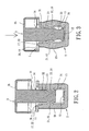
- Fig. 2 shows the bottle stopper of the first embodiment after assembly.
- the coupling portion 33 of the movable member 3 is engaged with the abutting portion 16 of the connecting plates 13 of the body 1.
- the diameter of the resilient member 2 has not be expanded yet (i.e., the resilient member 2 is in a smaller diameter state).
- the bottle stopper can easily be inserted into or removed from a mouth of a container or can still loosely seal the container.
- the movable member 3 when it is desired to tightly seal the mouth of the container with the bottle stopper, the movable member 3 is axially moved relative to the body 1 to proceed with a first-stage axial displacement. In this embodiment, the movable member 3 is pressed downward (as viewed from the drawing sheet) relative to the body 1. Thus, the abutting portion 32 of the shank 31 abuts against the abutting portions 16 of the connecting plates 13 of the body 1 to radially expand the connecting plates 13 of the body 1 and, hence, the resilient member 2. The mouth of the container is, thus, tightly sealed.
- the movable member 3 When it is desired to remove the bottle stopper from the mouth of the container, the movable member 3 is moved axially relative to the body 1 to proceed with a second-stage axial displacement. In this embodiment, the movable member 3 is pulled upward (as viewed from the drawing sheet) relative to the body 1. Thus, the coupling portion 33 of the movable member 3 is engaged with the abutting portion 16 of the connecting plates 13 of the body 1 (see Fig. 2 ). The resilient member 2 shrinks radially under action of its own resiliency to restore the smaller diameter state of the resilient member 2. In this state, the bottle stopper can easily be removed from the mouth of the container or loosely seal the container.
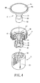
- an expansible bottle stopper of a second embodiment includes a body 4, a resilient member 5, and a movable member 6.
- the body 4 can be formed by injection molding of inert material such as plastics.
- the body 4 includes an annular wall 41 in the form of a cap.
- the annular wall 41 can be coupled with a cap made of metal, ceramic, china, wood, or glass materials.
- the annular wall 41 includes a circular hole 44 therein.
- a plurality of annularly spaced connecting plates 43 extend from an inner periphery of the circular hole 44, with a gap 45 formed between each two adjacent connecting plates 43.
- Each connecting plate 43 includes an abutting portion 46 extending radially inward toward the circular hole 44. In this embodiment, each abutting portion 46 directly extends inward toward the circular hole 44 from an outer side of one of the connecting plates 43. Distal ends of the connecting plates 43 are connected together by a bottom disc 42 to provide improved strength for the connecting plates 43.
- the resilient member 5 can be made of rubber or combined rubber/plastic materials by foaming to form an elastomer with appropriate compressibility.
- the resilient member 5 is cylindrical and engaged around the connecting plates 43 of the body 4.
- the resilient member 5 and the body 4 are integrally formed, with ribs 51 on the resilient member 5 fitted in the gaps 45 of the body 4, and with protrusions 52 on top of the resilient member 5 engaged in preserved slots 47 in the annular wall 41.
- the resilient member 5 includes a plurality of air guiding channels 53 on an outer periphery thereof, allowing gas in a container to be exhausted when the resilient member 5 is mounted in a mouth of the container.
- the movable member 6 can be made by injection molding of inert material such as plastics.
- the movable member 6 includes a disc 65 of a larger area and a shank 61 extending from a side of the disc 65.
- the disc 65 may be in the form of a cap.
- the disc 65 can be coupled with a cap made of metal, ceramic, china, wood, or glass materials.
- the shank 61 can be inserted into the circular hole 44 of the body 4.
- the shank 61 includes an abutting portion 62 that abuts against the abutting portion 46 of the body 4 such that the connecting plates 43 of the body 4 can push the resilient member 5 to expand radially.
- the shank 61 further includes a reduced coupling portion 63.
- the coupling portion 63 engages with the abutting portion 46 to cause radial shrinkage of the resilient member 5.
- the radial shrinkage extent of the resilient member 5 can be fixed by determining the difference between the diameter of the coupling portion 63 and the shank 61, with the resilient member 5 having a predetermined diameter according to designs.
- the disc 65 of the movable member 6 includes a ring 64 surrounding the disc 65 and connected to the outer periphery of the disc 65 by a fragile connecting portion 66.
- the connecting portion 66 breaks to cause disconnection of the ring 64 from the disc 65, with the movable member 6 sinking in the annular wall 41 of the body 4. Since the abutting portion 46 of the body 4 is engaged with the coupling portion 63 of the shank 61, the movable member 6 cannot move back to its initial position.
- Fig. 5 shows the bottle stopper of the second embodiment after assembly.
- the movable member 6 is in a free state allowing it to be inserted into or removed from the body 4.
- the movable member 6 when it is desired to tightly seal the mouth of the container with the bottle stopper, the movable member 6 is axially moved relative to the body 4 to proceed with a first-stage axial displacement.
- the movable member 6 is pressed downward (as viewed from the drawing sheet) relative to the body 4 to make the ring 64 and the disc 65 in contact with the top of the annular wall 41 of the body 4.
- the abutting portion 62 of the shank 61 abuts against the abutting portions 46 of the connecting plates 43 of the body 4.
- the connecting plates 43 of the body 4 expand radially to cause radial expansion of the resilient member 5 to thereby tightly seal the mouth of the container.
- the movable member 6 when it is desired to remove the bottle stopper from the mouth of the container, the movable member 6 is pressed downward relative to the body 4 to proceed with a second-stage axial displacement. At this time, the connecting portion 66 breaks and causes disconnection of the ring 64 from the disc 65, with the disc 65 sinking in the annular wall 41 of the body 4. Furthermore, the coupling portion 63 of the shank 61 engages with the abutting portions 46 of the connecting plates 43 of the body 4. Thus, besides destruction of the ring 64, the movable member 6 cannot return its initial position due to engagement between the coupling portion 63 of the movable member 6 and the abutting portions 46 of the body 4. This provides an anti-forgery effect.
- the resilient member 5 shrinks to its smaller diameter state under action of its resiliency. In this state, the bottle stopper can be removed from the mouth of the container.
- the diameter of the resilient member 5 after shrinkage can be designed according to the diameter of the coupling portion 63 of the shank 61 or the protruded extent of the abutting portions 46 of the connecting plates 43 of the body 4 such that the maximum diameter of the resilient member 5 is slightly larger than the inner diameter of the mouth of the container, allowing resealing of the mouth of the container by the bottle stopper.
- the bottle stopper of the present invention can radially expand by the first-stage axial displacement of the movable member relative to the body, and the diameter of the bottle stopper is larger than the inner diameter of the mouth of the container so that the resilient member can be fixedly and tightly press against the inner wall of the mouth of the container, obtaining enhanced sealing effect for the contents in the container. Furthermore, the resilient member shrinks radially by the second-stage axial displacement of the movable member relative to the body.
- the diameter of the resilient member can be set to a predetermined size to allow easy insertion or removal of the bottle stopper into or from the mouth of the container or to allow loosely sealing of the container by the bottle stopper.
- the connecting plates of the body are annularly arranged in a radial manner so that the connecting plates can expand radially to provide enhanced sealing effect between the bottle stopper and the container while having a simpler structure to cut the costs.
Landscapes
- Engineering & Computer Science (AREA)
- Mechanical Engineering (AREA)
- Closures For Containers (AREA)
Applications Claiming Priority (1)
| Application Number | Priority Date | Filing Date | Title |
|---|---|---|---|
| CN 200710143038 CN101372274B (zh) | 2007-08-21 | 2007-08-21 | 扩张式瓶塞 |
Publications (2)
| Publication Number | Publication Date |
|---|---|
| EP2028121A2 true EP2028121A2 (fr) | 2009-02-25 |
| EP2028121A3 EP2028121A3 (fr) | 2009-09-23 |
Family
ID=39941540
Family Applications (1)
| Application Number | Title | Priority Date | Filing Date |
|---|---|---|---|
| EP08013655A Withdrawn EP2028121A3 (fr) | 2007-08-21 | 2008-07-30 | Bouchon de bouteille extensible |
Country Status (2)
| Country | Link |
|---|---|
| EP (1) | EP2028121A3 (fr) |
| CN (1) | CN101372274B (fr) |
Cited By (2)
| Publication number | Priority date | Publication date | Assignee | Title |
|---|---|---|---|---|
| WO2011049487A1 (fr) * | 2009-10-23 | 2011-04-28 | Agarkov Andrey Vyacheslavovich | Bouchon pour bouteilles en verre |
| WO2011086407A3 (fr) * | 2010-01-15 | 2011-09-22 | Creative Gcl S.R.L. | Fermeture inviolable |
Families Citing this family (5)
| Publication number | Priority date | Publication date | Assignee | Title |
|---|---|---|---|---|
| CN102190115B (zh) * | 2010-03-11 | 2012-06-27 | 栓乐多瓶塞有限公司 | 两件式瓶塞 |
| CN104085596A (zh) * | 2014-07-07 | 2014-10-08 | 邓誉敏 | 一种多功能瓶塞 |
| CN105966740B (zh) * | 2016-07-13 | 2018-01-19 | 桂林电子科技大学 | 一种可快速开启和密封的红酒瓶塞 |
| CN108361376B (zh) * | 2017-12-28 | 2020-07-24 | 铜陵日科电子有限责任公司 | 一种变压器浸油机用密封盖 |
| US11312171B1 (en) | 2021-07-12 | 2022-04-26 | Richard Raymond Smith, Jr. | Can graphics concealment through pigmented overvarnish |
Citations (1)
| Publication number | Priority date | Publication date | Assignee | Title |
|---|---|---|---|---|
| TW467850B (en) | 2000-10-04 | 2001-12-11 | Sunlot Bottle Stopper Co Ltd | Bottle stopper |
Family Cites Families (8)
| Publication number | Priority date | Publication date | Assignee | Title |
|---|---|---|---|---|
| FR1067065A (fr) * | 1952-11-24 | 1954-06-11 | Bouchon à extension interne automatique | |
| GB1276485A (en) * | 1971-04-01 | 1972-06-01 | Paul Plura | Stoppers for necked bottles |
| WO2002036450A1 (fr) * | 2000-10-31 | 2002-05-10 | Sunlot Bottle Stopper Co., Ltd. | Bouchon de bouteille dilatable |
| JP3735347B2 (ja) * | 2001-04-11 | 2006-01-18 | サンロット ボトル ストッパー カンパニー リミテッド | ボトルプラグ |
| CN1150111C (zh) * | 2001-08-30 | 2004-05-19 | 栓乐多瓶塞有限公司 | 瓶塞 |
| CN1255307C (zh) * | 2003-03-05 | 2006-05-10 | 邱宏勇 | 膨胀收缩瓶塞 |
| DE10320269B3 (de) * | 2003-05-07 | 2004-10-14 | Reinhard Zills | Mehrweg - Verschlussstopfen für Wein-, Sekt- und Bierflaschen |
| CN2855928Y (zh) * | 2005-12-16 | 2007-01-10 | 烟台华新集团有限公司 | 一种胀紧式瓶盖 |
-
2007
- 2007-08-21 CN CN 200710143038 patent/CN101372274B/zh not_active Expired - Fee Related
-
2008
- 2008-07-30 EP EP08013655A patent/EP2028121A3/fr not_active Withdrawn
Patent Citations (1)
| Publication number | Priority date | Publication date | Assignee | Title |
|---|---|---|---|---|
| TW467850B (en) | 2000-10-04 | 2001-12-11 | Sunlot Bottle Stopper Co Ltd | Bottle stopper |
Cited By (4)
| Publication number | Priority date | Publication date | Assignee | Title |
|---|---|---|---|---|
| WO2011049487A1 (fr) * | 2009-10-23 | 2011-04-28 | Agarkov Andrey Vyacheslavovich | Bouchon pour bouteilles en verre |
| WO2011086407A3 (fr) * | 2010-01-15 | 2011-09-22 | Creative Gcl S.R.L. | Fermeture inviolable |
| US9114912B2 (en) | 2010-01-15 | 2015-08-25 | Guala Closures S.P.A. | Tamper evident closure |
| EA022140B1 (ru) * | 2010-01-15 | 2015-11-30 | Гуала Клоужурс С.П.А. | Укупорочное устройство с контролем вскрытия |
Also Published As
| Publication number | Publication date |
|---|---|
| CN101372274B (zh) | 2010-08-18 |
| CN101372274A (zh) | 2009-02-25 |
| EP2028121A3 (fr) | 2009-09-23 |
Similar Documents
| Publication | Publication Date | Title |
|---|---|---|
| US7850030B2 (en) | Expansible bottle stopper with radial expansion and shrinkage | |
| EP2028121A2 (fr) | Bouchon de bouteille extensible | |
| AU2001255182B2 (en) | Bottle stopper | |
| US6325226B1 (en) | Plastic screw closure | |
| US6551093B2 (en) | Mold assembly for a container closure | |
| US5673809A (en) | Container closure with a plastic liner having projections extending into depressions in the plastic shell | |
| US5460283A (en) | Sealing closure cap | |
| US6719160B2 (en) | Bottle stopper | |
| US5368178A (en) | Container and closure therefore having conical sealing surfaces | |
| AU2001255182A1 (en) | Bottle stopper | |
| US3430777A (en) | Pilferproof cap with integral pressure actuated sealing means | |
| EP3632806B1 (fr) | Ensemble de couvercle | |
| AU2002357595B2 (en) | Container main body made of synthetic resin and preforming mold device | |
| US6168036B1 (en) | Corkscrew-free bottle stopper | |
| CN203780992U (zh) | 容器的瓶盖 | |
| US5803281A (en) | Synthetic resinous container closure having frustoconical sealing surfaces | |
| KR20170038022A (ko) | 컨테이너와 클로저 및 그것의 제조 | |
| US3926329A (en) | Stopper of plastics having an expansible portion for bottles for sparkling wines and the like | |
| US3940005A (en) | Safety closure means for pressurized bottles and other like containers | |
| CN1960921B (zh) | 封闭元件 | |
| JP2018095291A (ja) | 開栓具付きキャップ | |
| CN209739733U (zh) | 一种防弹塞容器密封装置 | |
| JP6357605B1 (ja) | 容器用のキャップ | |
| EP1184295B1 (fr) | Bouchon pour bouteilles | |
| RU2088504C1 (ru) | Пробка для бутылок с шампанским или другими газированными жидкостями |
Legal Events
| Date | Code | Title | Description |
|---|---|---|---|
| PUAI | Public reference made under article 153(3) epc to a published international application that has entered the european phase |
Free format text: ORIGINAL CODE: 0009012 |
|
| 17P | Request for examination filed |
Effective date: 20080730 |
|
| AK | Designated contracting states |
Kind code of ref document: A2 Designated state(s): AT BE BG CH CY CZ DE DK EE ES FI FR GB GR HR HU IE IS IT LI LT LU LV MC MT NL NO PL PT RO SE SI SK TR |
|
| AX | Request for extension of the european patent |
Extension state: AL BA MK RS |
|
| PUAL | Search report despatched |
Free format text: ORIGINAL CODE: 0009013 |
|
| AK | Designated contracting states |
Kind code of ref document: A3 Designated state(s): AT BE BG CH CY CZ DE DK EE ES FI FR GB GR HR HU IE IS IT LI LT LU LV MC MT NL NO PL PT RO SE SI SK TR |
|
| AX | Request for extension of the european patent |
Extension state: AL BA MK RS |
|
| RIC1 | Information provided on ipc code assigned before grant |
Ipc: B65D 55/02 20060101ALI20090819BHEP Ipc: B65D 39/12 20060101AFI20081114BHEP |
|
| 17Q | First examination report despatched |
Effective date: 20100129 |
|
| AKX | Designation fees paid |
Designated state(s): AT BE BG CH CY CZ DE DK EE ES FI FR GB GR HR HU IE IS IT LI LT LU LV MC MT NL NO PL PT RO SE SI SK TR |
|
| RIC1 | Information provided on ipc code assigned before grant |
Ipc: B65D 55/02 20060101ALI20100803BHEP Ipc: B65D 39/12 20060101AFI20100803BHEP |
|
| GRAP | Despatch of communication of intention to grant a patent |
Free format text: ORIGINAL CODE: EPIDOSNIGR1 |
|
| STAA | Information on the status of an ep patent application or granted ep patent |
Free format text: STATUS: THE APPLICATION IS DEEMED TO BE WITHDRAWN |
|
| 18D | Application deemed to be withdrawn |
Effective date: 20110210 |