EP2028084A2 - Stanchion rod - Google Patents
Stanchion rod Download PDFInfo
- Publication number
- EP2028084A2 EP2028084A2 EP08161205A EP08161205A EP2028084A2 EP 2028084 A2 EP2028084 A2 EP 2028084A2 EP 08161205 A EP08161205 A EP 08161205A EP 08161205 A EP08161205 A EP 08161205A EP 2028084 A2 EP2028084 A2 EP 2028084A2
- Authority
- EP
- European Patent Office
- Prior art keywords
- stanchion
- runge
- stick according
- coupled
- stanchions
- Prior art date
- Legal status (The legal status is an assumption and is not a legal conclusion. Google has not performed a legal analysis and makes no representation as to the accuracy of the status listed.)
- Withdrawn
Links
Images

Classifications
-
- B—PERFORMING OPERATIONS; TRANSPORTING
- B62—LAND VEHICLES FOR TRAVELLING OTHERWISE THAN ON RAILS
- B62D—MOTOR VEHICLES; TRAILERS
- B62D33/00—Superstructures for load-carrying vehicles
- B62D33/02—Platforms; Open load compartments
- B62D33/0207—Connections of movable or detachable racks or stanchions to platforms
- B62D33/0215—Connections of movable or detachable racks or stanchions to platforms for log hauling vehicles
-
- B—PERFORMING OPERATIONS; TRANSPORTING
- B60—VEHICLES IN GENERAL
- B60P—VEHICLES ADAPTED FOR LOAD TRANSPORTATION OR TO TRANSPORT, TO CARRY, OR TO COMPRISE SPECIAL LOADS OR OBJECTS
- B60P3/00—Vehicles adapted to transport, to carry or to comprise special loads or objects
- B60P3/40—Vehicles adapted to transport, to carry or to comprise special loads or objects for carrying long loads, e.g. with separate wheeled load supporting elements
- B60P3/41—Vehicles adapted to transport, to carry or to comprise special loads or objects for carrying long loads, e.g. with separate wheeled load supporting elements for log transport
Definitions
- the present invention relates to a stanchion comprising a stanchion stool having first and second ends, and first and second stanchions, wherein the first stanchion is coupled to the first end of the stanchion stool and the second stanchion is coupled to the second end of the stanchion stool.
- Such Rungenstöcke are usually mounted on the bed of a truck or trailer and are mainly used in timber transport, but also in other areas, such as the transport of steel beams and the like.
- problems arise in locating the site, on the other hand, the space at the site are usually not known.
- the total length of truck and trailer is often more than 18 m, and thus, when the driver travels in the forest, maneuvering is almost impossible, is usually initially parked when first visiting the site of the trailer outside the forest. Only after finding the location of the trailer is coupled in a second step, the trailer at the parking place to the truck and then driven the combination of truck and trailer to the site. This is awkward, takes time and extra fuel.
- the present invention is therefore the object of developing a Rijnstock of the type mentioned in such a way that thereby the operation of with such stanchions equipped trucks and / or trailers, especially when used in the timber industry, is simplified.
- the present invention is based on the finding that this object can be achieved if it can be achieved that a trailer equipped with stanchions can be transported on the loading area of a truck equipped with stanchions.
- a crane is preferably provided on the truck, which also serves to load logs. It is by no means sufficient that only one stanchion can be folded down from the two stakes of a stanchion. Because if the other Runge remains in the erected state, results in a total height of truck and loaded trailer of more than 4.50 m, which is not allowed under the current law. If, however, as in the present invention, both stanchions so hinged coupled to the respective end of the stanchion that both stanchions are hinged simultaneously, the result is a total height of truck and loaded trailer of less than 4 m.
- the present invention not only increases the maneuverability of the truck and trailer combination when idling and minimizes tedious, nerve-wracking maneuvering, but also significantly reduces fuel consumption and brake and tire wear.
- diesel consumption can be reduced from 39 l to 36 l per 100 km.
- the combination of truck and trailer in the unloaded state in the traffic as well as on parking spaces instead of the required in an embodiment 18.75 m in length requires only 10.20 m and thus a possible Accident risk is significantly reduced. This is because, for example, crossing roads, entering them, overtaking, and overhauling on the basis of the present invention takes significantly less time.
- the trailer can be unloaded on both sides of the truck, depending on the space available. This possibility would not be given with only one foldable trained Runge pro Rurgistock. There, the trailer would have to be unloaded from the side to which it was charged. Especially in rough terrain, the invention offers an invaluable advantage due to this increase in flexibility.
- the first and the second stanchion is hingedly coupled to the respective end of the stanchion that both stanchions are arranged side by side in the folded state.
- the one Runge fits into a recess of the other Runge to allow a simultaneous folding of both stanchions, so the cheapest alternative, however, is that the first stanchion and / or the second Runge in the folded state by a predetermined angle is pivoted against the stanchion stool.
- standard stanchions can be used, which are available at lower prices than specially trained stanchions.
- a stanchion without swivel angle the other is designed hinged with a slightly larger swivel angle, it is still preferable that both stanchions are pivoted in the folded state by a predetermined angle relative to the stanchion stool.
- the one stanchion is pivoted in one direction of Runge stool, the other Runge in the other direction of Runge stool.
- a comparatively stable arrangement can be achieved; the modifications to both To allow stanchions to pivot, are the same in both stakes, so that there is a more favorable realization.
- the amount of the predetermined pivot angle is between 3 degrees and 20 degrees, more preferably between 3 degrees and 8 degrees.
- At least one end of the stanchion stool has an outer surface at an angle to the longitudinal extension of the stanchion stool, which corresponds to 90 degrees +/- the predetermined angle. This can be accomplished by, for example, slanting one end off each side of a standard commercial stanchion stool, d. H. in the predetermined angle, is separated.
- the coupling of at least one stanchion with the associated end of the stanchion stool preferably comprises a hinged hinge coupled to the end of the stanchion and a stanchion pocket coupled to the hinged hinge, the stanchion being inserted into the stanchion pocket, the hinged hinge being arranged at the predeterminable angle relative to the stanchion stool ,
- the aforementioned oblique separation of an end of a commercial Runge stool is made at a distance which corresponds substantially to the longitudinal extent of the hinged hinge. Since the predeterminable angle is reflected in the assembly of the hinged hinge on the stanchion, a standard stanchion pocket can be inserted into the hinged hinge to receive the stanchion therein.
- the coupling of the stanchion with the associated end of the stanchion stool preferably has a receptacle for an operating device for folding up and down the stanchion. This is preferably arranged so that it points at an angle of substantially 30 to 60 degrees, preferably 45 degrees down with unfolded stanchion. As a result, the operating device can be conveniently used while providing a sufficient lever arm with the stanchion folded and conveniently removed again when the stanchion is folded down, and vice versa.
- a spring device is further provided, which is so coupled to the Runge on the one hand, preferably with the Rurgitician, and the Runge stool on the other hand, that the unfolding of the stanchion is supported by the spring device.
- a stanchion having a telescoping device comprising a telescoping shelf disposed in the stanchion.
- a stanchion can be used particularly advantageously with a stanchion according to the invention, but can also be used independently of it, i. for non-hinged stanchions, as will be apparent to those skilled in the art.
- This opens up the possibility of still allowing a loading height of the cargo of more than this width while maintaining a maximum permissible vehicle width of 2.55 m.
- the telescopic extension an additional height of the unfolded, thus equipped stanchion of 27 cm.
- a manual clamping device is further provided to clamp the telescopic extension, at least in the extended position, fixed to the stanchion.
- a push rod is still provided, which is coupled on the one hand with the telescopic extension and on the other hand supported on a stop for the push rod, such that when unfolding the Runge the telescopic extension is pushed out of the stanchion. Conversely, when the stanchion is folded down, the telescopic attachment is pushed into the stanchion.
- the stop for the push rod is fixed in position coupled to the stanchion stool.
- the push rod has a joint to allow kinking of the push rod. By this measure, the push rod over the entire folding angle, which is approximately 90 degrees, do their job.
- a pneumatic or hydraulic cylinder is provided, which is coupled to the telescopic extension, that upon actuation of the pneumatic or hydraulic cylinder of the telescopic extension is pushed out of the stanchion.
- the pneumatic or hydraulic cylinder is arranged in the stanchion.
- a rope provided, which is coupled on the one hand with the telescopic extension and on the other hand, preferably via a pulley, is coupled to the stanchion, such that when applying the pneumatic or hydraulic cylinder with pressure continue the stanchion from the folded and the unfolded Condition is moved.
- the stanchion is simultaneously unfolded by the extension of the telescopic extension, resulting in a particularly large time savings and in a particularly easy-to-use embodiment.
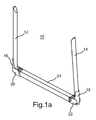
- Fig. 1a shows a schematic representation of an embodiment of a stanchion 10 according to the invention.
- This comprises a first 12 and a second stanchion 14, which are hollow and are fastened to a stanchion 24 via a respective stanchion pocket 16, 18 and a respective folding hinge 20, 22.
- the stanchions 12, 14 have in the exemplary embodiment a substantially oval cross section, but may also have a round or rectangular cross section.
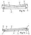
- Fig. 1b shows a front view of the representation of Fig. 1a
- Fig. 1c a top view of the representation of Fig. 1a shows.
- Out Fig. 1b shows that the two stanchions 12, 14 come to rest in the folded state next to each other. How out Fig. 1c clearly visible, the two stanchions 12, 14 extend in the folded state substantially parallel. Both stanchions 12, 14 enclose an angle ⁇ of approximately 4 degrees with the stanchion stool.
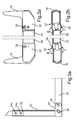
- Fig. 2a shows a view from the front of the combination of respective stanchion pocket 16, 18, respective folding hinge 20, 22 and shortened Runge stool 24. Clearly, respective pivot pins 26, 28 can be seen. In the presentation of Fig. 2a no stanchions are used, but standard stanchions could be included in the stanchion pockets 16, 18.
- Fig. 2b shows a plan view of the representation of Fig. 2a .
- Good to see are the kinks in the course of the combination.
- the respective angle ⁇ is about 176 degrees, while the respective angle ⁇ is about 184 degrees.
- FIGS. 3a to 3c show different embodiments of a telescopic stanchion, as they can be used particularly advantageously in conjunction with a Rurgistock invention.
- telescoping stanchions may be what the embodiment of FIG Fig. 3a relates to be used in combination with any Rurgistock.
- Fig. 3b and 3c can be used with a Rungenstock with hinged stanchions. The latter need not be designed so that a simultaneous folding of the two stanchions of a stanchion is possible.
- Fig. 3a shows the example of the left stanchion 12 of the embodiment of the FIGS. 1a to 1c a first embodiment of a telescopic Runge.
- the left side of the stanchion 10 has been shown, the right side being constructed symmetrically thereto.
- a receptacle 30 for an operating device in particular a rod or a hand lever, is provided on the hinge 20.
- a telescopic extension 32 is arranged, which can be clamped in the stanchion 12 by means of two manual clamping devices 34a, 34b.
- a push rod 36 is provided, which is on the one hand connected to the telescopic extension 32, on the other hand is supported at the point P to a stop 38 which is fixedly connected to the Runge stool 24.
- the push rod has a hinge 40 to perform its function throughout the folding operation, i. H. both when unfolding and when folding, to meet.
- Fig. 3c shows a further embodiment of a telescopic Runge, in which a pneumatic cylinder 42 is coupled via a piston rod 44 with the telescopic extension 32.
- the pneumatic cylinder 42 is fixedly mounted on the inside of the stanchion 12.
- the compressed air supply line is designated 46. It also has a steel cable 48, which is also coupled via a deflection roller 50 with the telescopic extension 32. This results in that upon actuation of the pneumatic cylinder 42 with pressure with folded Runge 12 on the one hand, the telescopic extension 32 is extended, thereby the steel cable 48 is tensioned, whereby the stanchion 12 is automatically opened. If the application of pressure is withdrawn, the stanchion is simultaneously folded while the telescopic extension 32 is inserted.
- a compressed air cylinder 42 may also be provided a corresponding hydraulic device.
Abstract
Description
Die vorliegende Erfindung betrifft einen Rungenstock umfassend einen Rungenschemel, der ein erstes und ein zweites Ende aufweist, und eine erste und eine zweite Runge, wobei die erste Runge mit dem ersten Ende des Rungenschemels und die zweite Runge mit dem zweiten Ende des Rungenschemels gekoppelt ist.The present invention relates to a stanchion comprising a stanchion stool having first and second ends, and first and second stanchions, wherein the first stanchion is coupled to the first end of the stanchion stool and the second stanchion is coupled to the second end of the stanchion stool.
Derartige Rungenstöcke werden üblicherweise auf der Ladefläche von einem LKW oder einem Anhänger montiert und werden überwiegend im Holztransport, jedoch auch in anderen Bereichen, beispielsweise beim Transport von Stahlträgern und dergleichen, eingesetzt. Insbesondere bei einem Einsatz zum Holztransport ergeben sich zahlreiche Nachteile: Da der Einsatzort im Wald naturgemäß laufend wechselt, ergeben sich einerseits Probleme beim Auffinden des Einsatzortes, andererseits sind die Platzverhältnisse am Einsatzort gewöhnlich nicht bekannt. Da die Gesamtlänge aus LKW und Anhänger häufig mehr als 18 m beträgt, und damit, wenn sich der Fahrer im Wald verfährt, ein Rangieren nahezu unmöglich ist, wird üblicherweise zunächst beim erstmaligen Aufsuchen des Einsatzortes der Anhänger außerhalb des Waldes geparkt. Erst nach dem Auffinden des Einsatzortes wird in einem zweiten Schritt der Anhänger am Abstellort an den LKW angekoppelt und anschließend die Kombination aus LKW und Anhänger zum Einsatzort gefahren. Dies ist umständlich, kostet Zeit und zusätzlichen Kraftstoff.Such Rungenstöcke are usually mounted on the bed of a truck or trailer and are mainly used in timber transport, but also in other areas, such as the transport of steel beams and the like. In particular, when used for timber transport, there are numerous disadvantages: Since the place of use in the forest naturally constantly changes, on the one hand problems arise in locating the site, on the other hand, the space at the site are usually not known. Since the total length of truck and trailer is often more than 18 m, and thus, when the driver travels in the forest, maneuvering is almost impossible, is usually initially parked when first visiting the site of the trailer outside the forest. Only after finding the location of the trailer is coupled in a second step, the trailer at the parking place to the truck and then driven the combination of truck and trailer to the site. This is awkward, takes time and extra fuel.
Der vorliegenden Erfindung liegt deshalb die Aufgabe zugrunde, einen Rungenstock der eingangs genannten Art derart weiterzubilden, dass dadurch die Bedienung von mit derartigen Rungenstöcken ausgestatteten LKWs und/oder Anhängern, insbesondere beim Einsatz in der Holzwirtschaft, vereinfacht wird.The present invention is therefore the object of developing a Rungenstock of the type mentioned in such a way that thereby the operation of with such stanchions equipped trucks and / or trailers, especially when used in the timber industry, is simplified.
Diese Aufgabe wird gelöst durch einen Rungenstock mit den Merkmalen von Patentanspruch 1.This object is achieved by a stanchion with the features of claim 1.
Der vorliegenden Erfindung liegt die Erkenntnis zugrunde, dass diese Aufgabe gelöst werden kann, wenn erreicht werden kann, dass einer mit Rungenstöcken ausgestatteter Anhänger auf der Ladefläche eines mit Rungenstöcken ausgestatteten LKWs transportiert werden kann. Dafür ist bevorzugt ein Kran am LKW vorgesehen, der auch dem Aufladen von Baumstämmen dient. Dabei ist es keinesfalls ausreichend, dass von den beiden Rungen eines Rungenstocks lediglich eine Runge abgeklappt werden kann. Denn wenn die andere Runge im aufgestellten Zustand verbleibt, ergibt sich eine Gesamthöhe aus LKW und darauf geladenem Anhänger von mehr als 4,50 m, die bei der gegenwärtigen Gesetzeslage nicht erlaubt ist. Werden hingegen, wie bei der vorliegenden Erfindung, beide Rungen derart klappbar mit dem jeweiligen Ende des Rungenschemels gekoppelt, dass beide Rungen gleichzeitig abklappbar sind, so ergibt sich eine Gesamthöhe aus LKW und geladenem Anhänger von weniger als 4 m.The present invention is based on the finding that this object can be achieved if it can be achieved that a trailer equipped with stanchions can be transported on the loading area of a truck equipped with stanchions. For this purpose, a crane is preferably provided on the truck, which also serves to load logs. It is by no means sufficient that only one stanchion can be folded down from the two stakes of a stanchion. Because if the other Runge remains in the erected state, results in a total height of truck and loaded trailer of more than 4.50 m, which is not allowed under the current law. If, however, as in the present invention, both stanchions so hinged coupled to the respective end of the stanchion that both stanchions are hinged simultaneously, the result is a total height of truck and loaded trailer of less than 4 m.
Würde bei einem Rungenstock nur eine Runge klappbar ausgebildet sein, könnte die maximal erlaubte Gesamthöhe von 4 m nur dann eingehalten werden, wenn aufwändige Umbaumaßnahmen am LKW vorgenommen würden zum Zwecke des Schaffens von Platz für die Räder des Anhängers. Dazu müssten insbesondere der Batteriekasten und der Luftkessel abgesenkt werden; Spezialtanks für Kraftstoff und Hydrauliköl, sowie weitere aufwändige Umbauarbeiten am LKW wären nötig.If only one stanchion would be foldable in a stanchion, the maximum permitted total height of 4 m could only be maintained if elaborate conversion measures were made on the truck for the purpose of creating space for the wheels of the trailer. For this purpose, in particular the battery box and the air tank would have to be lowered; Special tanks for fuel and hydraulic oil, as well as other elaborate modifications to the truck would be necessary.
Durch die vorliegende Erfindung wird nicht nur die Wendigkeit der Kombination aus LKW und Anhänger bei Leerfahrten erhöht und werden langwierige, nervenaufreibende Rangierfahrten minimiert, sondern es wird auch eine deutliche Minderung des Kraftstoffverbrauchs und des Brems- und Reifenverschleißes erreicht. So lässt sich in einem bevorzugten Ausführungsbeispiel der Dieselverbrauch von 39 I auf 36 I pro 100 km senken. Hinzu kommt, dass die Kombination aus LKW und Anhänger im unbeladenen Zustand im Straßenverkehr ebenso wie auf Abstellplätzen statt der in einem Ausführungsbeispiel benötigten 18,75 m Länge nur 10,20 m benötigt und somit ein etwaiges Unfallrisiko deutlich gemindert wird. Dies liegt daran, dass beispielsweise das Überqueren von Straßen, das Einbiegen in diese, das Überholen sowie das Überholtwerden auf der Basis der vorliegenden Erfindung deutlich weniger Zeit beansprucht.The present invention not only increases the maneuverability of the truck and trailer combination when idling and minimizes tedious, nerve-wracking maneuvering, but also significantly reduces fuel consumption and brake and tire wear. Thus, in a preferred embodiment, diesel consumption can be reduced from 39 l to 36 l per 100 km. In addition, the combination of truck and trailer in the unloaded state in the traffic as well as on parking spaces instead of the required in an embodiment 18.75 m in length requires only 10.20 m and thus a possible Accident risk is significantly reduced. This is because, for example, crossing roads, entering them, overtaking, and overhauling on the basis of the present invention takes significantly less time.
Gemäß der vorliegenden Erfindung kann überdies der Anhänger auf beiden Seiten des LKWs abgeladen werden, je nach dem zur Verfügung stehenden Raum. Diese Möglichkeit wäre bei nur einer klappbar ausgebildeten Runge pro Rungenstock nicht gegeben. Dort müsste der Anhänger von der Seite abgeladen werden, auf die er aufgeladen wurde. Insbesondere im unwegsamen Gelände bietet die Erfindung hier aufgrund dieses Flexibilitätszuwachses einen unschätzbaren Vorteil.According to the present invention, moreover, the trailer can be unloaded on both sides of the truck, depending on the space available. This possibility would not be given with only one foldable trained Runge pro Rungenstock. There, the trailer would have to be unloaded from the side to which it was charged. Especially in rough terrain, the invention offers an invaluable advantage due to this increase in flexibility.
Schließlich ergibt sich bei Leerfahrten eine deutliche Mautersparnis auf mautpflichtigen Straßen, da anstelle von fünf Achsen nur zwei Achsen bezahlt werden müssen.Finally, there is a clear toll reduction on toll roads for empty runs, since only two axles have to be paid instead of five axles.
Gemäß einer bevorzugten Ausführungsform ist die erste und die zweite Runge derart klappbar mit dem jeweiligen Ende des Rungenschemels gekoppelt, dass beide Rungen im abgeklappten Zustand nebeneinander anordenbar sind. Dadurch lässt sich eine minimale Gesamthöhe der Kombination aus LKW und darauf geladenem Anhänger erzielen.According to a preferred embodiment, the first and the second stanchion is hingedly coupled to the respective end of the stanchion that both stanchions are arranged side by side in the folded state. As a result, a minimum total height of the combination of truck and loaded trailer can be achieved.
Wenngleich vorgesehen werden könnte, dass sich die eine Runge in eine Aussparung der anderen Runge einfügt, um ein gleichzeitiges Abklappen beider Rungen zu ermöglichen, so besteht die kostengünstigste Alternative jedoch darin, dass die erste Runge und/oder die zweite Runge im abgeklappten Zustand um einen vorgebbaren Winkel gegenüber dem Rungenschemel verschwenkt ist. Dadurch lassen sich nämlich Standard-Rungen verwenden, die zu günstigeren Preisen erhältlich sind als speziell ausgebildete Rungen. Wenngleich vorgesehen sein könnte, dass eine Runge ohne Schwenkwinkel, die andere dafür mit einem etwas größeren Schwenkwinkel abklappbar ausgebildet ist, so ist dennoch bevorzugt, dass beide Rungen im abgeklappten Zustand um einen vorgebbaren Winkel gegenüber dem Rungenschemel verschwenkt sind. Dabei ist die eine Runge in die eine Richtung des Rungenschemels, die andere Runge in die andere Richtung des Rungenschemels verschwenkt. Dadurch lässt sich eine vergleichsweise stabile Anordnung erzielen; die Modifikationen, um bei beiden Rungen ein Schwenken zu ermöglichen, sind bei beiden Rungen dieselben, so dass sich eine günstigere Realisierung ergibt.Although it could be provided that the one Runge fits into a recess of the other Runge to allow a simultaneous folding of both stanchions, so the cheapest alternative, however, is that the first stanchion and / or the second Runge in the folded state by a predetermined angle is pivoted against the stanchion stool. As a result, standard stanchions can be used, which are available at lower prices than specially trained stanchions. Although it could be provided that a stanchion without swivel angle, the other is designed hinged with a slightly larger swivel angle, it is still preferable that both stanchions are pivoted in the folded state by a predetermined angle relative to the stanchion stool. Here, the one stanchion is pivoted in one direction of Runge stool, the other Runge in the other direction of Runge stool. As a result, a comparatively stable arrangement can be achieved; the modifications to both To allow stanchions to pivot, are the same in both stakes, so that there is a more favorable realization.
Bevorzugt beträgt der Betrag des vorgebbaren Schwenkwinkels zwischen 3 Grad und 20 Grad, noch bevorzugter zwischen 3 Grad und 8 Grad.Preferably, the amount of the predetermined pivot angle is between 3 degrees and 20 degrees, more preferably between 3 degrees and 8 degrees.
Bei der Realisierung der vorliegenden Erfindung ist es besonders bevorzugt, dass mindestens ein Ende des Rungenschemels eine Außenfläche in einem Winkel zur Längserstreckung des Rungenschemels aufweist, der 90 Grad +/- dem vorgebbaren Winkel entspricht. Dies kann erreicht werden, indem beispielsweise von einem normalen, handelsüblichen Rungenschemel auf jeder Seite ein Ende schräg, d. h. in dem vorgebbaren Winkel, abgetrennt wird.In realizing the present invention, it is particularly preferred that at least one end of the stanchion stool has an outer surface at an angle to the longitudinal extension of the stanchion stool, which corresponds to 90 degrees +/- the predetermined angle. This can be accomplished by, for example, slanting one end off each side of a standard commercial stanchion stool, d. H. in the predetermined angle, is separated.
Bevorzugt umfasst die Kopplung mindestens einer Runge mit dem zugehörigen Ende des Rungenschemels ein mit dem Ende des Rungenschemels gekoppeltes Klappscharnier und eine mit dem Klappscharnier gekoppelte Rungentasche, wobei die Runge in die Rungentasche eingesetzt ist, wobei das Klappscharnier gegenüber dem Rungenschemel in dem vorgebbaren Winkel angeordnet ist. Bei der Realisierung dieser Variante wird das zuvor erwähnte schräge Abtrennen eines Endes eines handelsüblichen Rungenschemels in einem Abstand vorgenommen, der im Wesentlichen der Längserstreckung des Klappscharniers entspricht. Da sich der vorgebbare Winkel in der Montage des Klappscharniers an dem Rungenschemel widerspiegelt, kann eine Standardrungentasche in das Klappscharnier eingesetzt werden, um darin die Runge aufzunehmen.The coupling of at least one stanchion with the associated end of the stanchion stool preferably comprises a hinged hinge coupled to the end of the stanchion and a stanchion pocket coupled to the hinged hinge, the stanchion being inserted into the stanchion pocket, the hinged hinge being arranged at the predeterminable angle relative to the stanchion stool , In the implementation of this variant, the aforementioned oblique separation of an end of a commercial Runge stool is made at a distance which corresponds substantially to the longitudinal extent of the hinged hinge. Since the predeterminable angle is reflected in the assembly of the hinged hinge on the stanchion, a standard stanchion pocket can be inserted into the hinged hinge to receive the stanchion therein.
Bevorzugt weist die Kopplung der Runge mit dem zugehörigen Ende des Rungenschemels eine Aufnahme für eine Bedienvorrichtung zum Auf- und Abklappen der Runge auf. Diese ist bevorzugt so angeordnet, dass sie bei aufgeklappter Runge in einem Winkel von im Wesentlichen 30 bis 60 Grad, bevorzugt 45 Grad nach unten weist. Dadurch kann die Bedienvorrichtung unter Bereitstellung eines ausreichenden Hebelarms bei aufgeklappter Runge bequem eingesetzt und bei abgeklappter Runge bequem wieder abgezogen werden und umgekehrt.The coupling of the stanchion with the associated end of the stanchion stool preferably has a receptacle for an operating device for folding up and down the stanchion. This is preferably arranged so that it points at an angle of substantially 30 to 60 degrees, preferably 45 degrees down with unfolded stanchion. As a result, the operating device can be conveniently used while providing a sufficient lever arm with the stanchion folded and conveniently removed again when the stanchion is folded down, and vice versa.
Bevorzugt ist weiterhin eine Federvorrichtung vorgesehen, die derart mit der Runge einerseits, bevorzugt mit der Rungentasche, und dem Rungenschemel andererseits gekoppelt ist, dass das Aufklappen der Runge durch die Federvorrichtung unterstützt wird.Preferably, a spring device is further provided, which is so coupled to the Runge on the one hand, preferably with the Rungentasche, and the Runge stool on the other hand, that the unfolding of the stanchion is supported by the spring device.
Gemäß einem weiteren Aspekt der vorliegenden Erfindung wird eine Runge bereitgestellt, die eine Teleskopiervorrichtung aufweist, die einen in der Runge angeordneten Teleskopausschub umfasst. Eine derartige Runge kann besonders vorteilhaft mit einem erfindungsgemäßen Rungenstock eingesetzt werden, lässt sich jedoch auch unabhängig davon, d.h. bei nicht klappbaren Rungenstöcken, verwenden, wie für den Fachmann offensichtlich ist. Diese eröffnet die Möglichkeit, bei Einhaltung einer maximal zulässigen Fahrzeugbreite von 2,55 m dennoch eine Ladehöhe des Ladeguts von mehr als dieser Breite zu ermöglichen. In einem bevorzugten Ausführungsbeispiel lässt sich durch den Teleskopausschub eine zusätzliche Höhe der aufgeklappten, damit ausgestatteten Runge von 27 cm erzielen. In einer einfachen, kostengünstigen Variante ist dazu weiterhin eine manuelle Klemmvorrichtung vorgesehen, um den Teleskopausschub zumindest in ausgeschobener Stellung lagefest zur Runge zu klemmen.According to another aspect of the present invention, there is provided a stanchion having a telescoping device comprising a telescoping shelf disposed in the stanchion. Such a stanchion can be used particularly advantageously with a stanchion according to the invention, but can also be used independently of it, i. for non-hinged stanchions, as will be apparent to those skilled in the art. This opens up the possibility of still allowing a loading height of the cargo of more than this width while maintaining a maximum permissible vehicle width of 2.55 m. In a preferred embodiment can be achieved by the telescopic extension an additional height of the unfolded, thus equipped stanchion of 27 cm. In a simple, inexpensive variant, a manual clamping device is further provided to clamp the telescopic extension, at least in the extended position, fixed to the stanchion.
Gemäß einer bevorzugten Ausführungsform ist jedoch weiterhin eine Schubstange vorgesehen, die einerseits mit dem Teleskopausschub gekoppelt ist und andererseits an einem Anschlag für die Schubstange abgestützt ist, derart, dass beim Aufklappen der Runge der Teleskopausschub aus der Runge ausgeschoben wird. Umgekehrt wird beim Abklappen der Runge der Teleskopaufsatz in die Runge eingeschoben. Dadurch lassen sich zwei zeitaufwändige Prozesse kombinieren, was in einer deutlichen Zeitersparnis resultiert, wenn man die Vielzahl an Rungen betrachtet, die in Summe an einem LKW und an einem Anhänger montiert sind.According to a preferred embodiment, however, a push rod is still provided, which is coupled on the one hand with the telescopic extension and on the other hand supported on a stop for the push rod, such that when unfolding the Runge the telescopic extension is pushed out of the stanchion. Conversely, when the stanchion is folded down, the telescopic attachment is pushed into the stanchion. This can be combined with two time-consuming processes, which results in a significant time savings, considering the large number of stanchions that are mounted in total on a truck and on a trailer.
Bevorzugt ist der Anschlag für die Schubstange lagefest mit dem Rungenschemel gekoppelt. Weiterhin ist bevorzugt, wenn die Schubstange ein Gelenk aufweist, um ein Abknicken der Schubstange zu ermöglichen. Durch diese Maßnahme kann die Schubstange über den gesamten Klappwinkel, der in etwa 90 Grad beträgt, ihre Aufgabe erfüllen.Preferably, the stop for the push rod is fixed in position coupled to the stanchion stool. Furthermore, it is preferred if the push rod has a joint to allow kinking of the push rod. By this measure, the push rod over the entire folding angle, which is approximately 90 degrees, do their job.
Bei einer noch bevorzugteren Weiterbildung ist ein Pneumatik- oder Hydraulikzylinder vorgesehen, der derart mit dem Teleskopausschub gekoppelt ist, dass bei Beaufschlagung des Pneumatik- oder Hydraulikzylinders der Teleskopausschub aus der Runge ausgeschoben wird. Dadurch wird der kraftaufwändige manuelle Prozess der Teleskopierung deutlich vereinfacht und beschleunigt. Bevorzugt ist dabei der Pneumatik- oder Hydraulikzylinder in der Runge angeordnet.In a more preferred embodiment, a pneumatic or hydraulic cylinder is provided, which is coupled to the telescopic extension, that upon actuation of the pneumatic or hydraulic cylinder of the telescopic extension is pushed out of the stanchion. This significantly simplifies and speeds up the laborious manual process of telescoping. Preferably, the pneumatic or hydraulic cylinder is arranged in the stanchion.
Besonders bevorzugt ist dabei weiterhin ein Seil vorgesehen, das einerseits mit dem Teleskopausschub gekoppelt ist und andererseits, bevorzugt über eine Umlenkrolle, mit dem Rungenschemel gekoppelt ist, derart, dass beim Beaufschlagen des Pneumatik-oder Hydraulikzylinders mit Druck weiterhin die Runge vom abgeklappten und den aufgeklappten Zustand bewegt wird. Damit wird durch das Ausfahren des Teleskopausschubs gleichzeitig die Runge aufgeklappt, was in einer besonders großen Zeitersparnis und in einer besonders leicht zu bedienenden Ausführungsform resultiert.Particularly preferred is still a rope provided, which is coupled on the one hand with the telescopic extension and on the other hand, preferably via a pulley, is coupled to the stanchion, such that when applying the pneumatic or hydraulic cylinder with pressure continue the stanchion from the folded and the unfolded Condition is moved. Thus, the stanchion is simultaneously unfolded by the extension of the telescopic extension, resulting in a particularly large time savings and in a particularly easy-to-use embodiment.
Durch die beiden letztgenannten Ausführungsformen, d.h. der Realisierung einer teleskopierbaren Runge mittels einer Schubstange oder mittels eines Pneumatik- oder Hydraulikzylinders wird gleichzeitig mit dem Aufklappen der Runge dieselbe gegen ein Umfallen gesichert. In anbetracht des Gewichts einer Runge können dadurch Beschädigungen am Fahrzeug und Verletzungen der Bedienperson verhindert werden.By the two latter embodiments, i. the realization of a telescopic stanchion by means of a push rod or by means of a pneumatic or hydraulic cylinder is simultaneously secured with the unfolding of the stanchion against falling over. In view of the weight of a stanchion damage to the vehicle and injury to the operator can be prevented.
Weitere bevorzugte Ausführungsformen ergeben sich aus den Unteransprüchen.Further preferred embodiments emerge from the subclaims.
Im Nachfolgenden werden nunmehr Ausführungsbeispiele der vorliegenden Erfindung unter Bezugnahme auf die beigefügten Zeichnungen näher beschrieben. Es zeigen:
- Fig. 1a
- in schematischer Darstellung ein Ausführungsbeispiel eines erfindungsgemäßen Rungenstocks mit aufgeklappten Rungen;
- Fig. 1 b
- eine Ansicht von vorne des Rungenstocks von
Fig. 1a mit abgeklappten Rungen; - Fig. 1 c
- eine Draufsicht auf den Rungenstock von
Fig. 1a mit abgeklappten Rungen;
- Fig. 2a
- eine Ansicht von vorne auf die an beiden Enden des Rungenschemels montierten Klappscharniere und damit verbundenen Rungentaschen ohne eingesetzte Rungen;
- Fig. 2b
- die Kombination von
Fig. 2a in Draufsicht; - Fig. 3a
- in schematischer Darstellung ein erstes Ausführungsbeispiel einer Runge mit einer teleskopierbaren Runge;
- Fig. 3b
- in schematischer Darstellung ein zweites Ausführungsbeispiel einer teleskopierbaren Runge; und
- Fig. 3c
- in schematischer Darstellung ein drittes Ausführungsbeispiel einer teleskopierbaren Runge.
- Fig. 1a
- a schematic representation of an embodiment of a stanchion according to the invention with unfolded stanchions;
- Fig. 1 b
- a view from the front of the Rungenstock of
Fig. 1a with folded stanchions; - Fig. 1 c
- a plan view of the Rungenstock of
Fig. 1a with folded stanchions;
- Fig. 2a
- a view from the front on the hinged hinges mounted at both ends of the stanchion and associated stanchion pockets without stakes;
- Fig. 2b
- the combination of
Fig. 2a in plan view; - Fig. 3a
- a schematic representation of a first embodiment of a stanchion with a telescopic stanchion;
- Fig. 3b
- a schematic representation of a second embodiment of a telescopic stanchion; and
- Fig. 3c
- a schematic representation of a third embodiment of a telescopic Runge.
In den verschiedenen Figuren werden für gleiche Bauelemente gleiche Bezugszeichen verwendet.In the various figures, like reference numerals are used for like components.
Die
Zur Vereinfachung des Ab- und Aufklappens ist am Scharnier 20 eine Aufnahme 30 für eine Bedienvorrichtung, insbesondere eine Stange oder einen Handhebel, vorgesehen. In der Runge 12 ist ein Teleskopausschub 32 angeordnet, der mittels zweier manueller Klemmvorrichtungen 34a, 34b in der Runge 12 festgeklemmt werden kann.To simplify the folding and unfolding, a
Gemäß dem Ausführungsbeispiel von
Die Schubstange weist ein Gelenk 40 auf, um ihre Funktion während des gesamten Umklappvorgangs, d. h. sowohl beim Aufklappen als auch beim Abklappen, zu erfüllen.The push rod has a
Claims (16)
dadurch gekennzeichnet,
dass die erste und die zweite Runge (12, 14) derart klappbar mit dem jeweiligen Ende des Rungenschemels (24) gekoppelt sind, dass beide Rungen (12, 14) gleichzeitig einklappbar sind.A stanchion comprising a stanchion stool (24) having first and second ends, and first and second stanchions (12, 14), the first stanchion (12) connected to the first end of the stanchion (24) and the second stanchion (14) is coupled to the second end of the stanchion (24),
characterized,
in that the first and the second stanchions (12, 14) are hingedly coupled to the respective end of the stanchion (24) in such a way that both stanchions (12, 14) can be folded in at the same time.
dadurch gekennzeichnet,
dass die erste und die zweite Runge (12, 14) derart klappbar mit dem jeweiligen Endes des Rungenschemels (24) gekoppelt sind, dass beide Rungen (12, 14) im eingeklappten Zustand nebeneinander anordenbar sind.Runge stick according to claim 1,
characterized,
in that the first and the second stanchions (12, 14) are hingedly coupled to the respective end of the stanchion (24) in such a way that both stanchions (12, 14) can be arranged side by side in the folded-in state.
dadurch gekennzeichnet,
dass die erste Runge (12) und/oder die zweite Runge (14) im eingeklappten Zustand um einen vorgebbaren Winkel (α) gegenüber dem Rungenschemel (24) verschwenkt sind/ist.Runge stick according to one of claims 1 or 2,
characterized,
that the first stanchion (12) and / or the second stanchion (14) is / are pivoted in the folded state by a predeterminable angle (α) with respect to the stanchion (24).
dadurch gekennzeichnet,
dass der Betrag des vorgebbaren Winkels (α) zwischen 3 Grad und 20 Grad, bevorzugt zwischen 3 Grad und 8 Grad beträgt.Runge stick according to claim 3,
characterized,
the amount of the predetermined angle (α) of between 3 degrees and 20 degrees, preferably between 3 degrees and 8 degrees.
dadurch gekennzeichnet,
dass mindestens ein Ende des Rungenschemels (24) eine Außenfläche in einem Winkel zur Längserstreckung des Rungenschemels (24) aufweist, der 90 Grad +/- dem vorgebbaren Winkel entspricht.Runge stick according to one of claims 3 or 4,
characterized,
in that at least one end of the stanchion (24) has an outer surface at an angle to the longitudinal extension of the stanchion (24), which corresponds to 90 degrees +/- the predetermined angle.
dadurch gekennzeichnet,
dass die Kopplung mindestens einer Runge (12; 14) mit dem zugehörigen Ende des Rungenschemels (24) ein mit dem Ende des Rungenschemels (24) gekoppeltes Klappscharnier (20; 22) und eine mit dem Klappscharnier (20; 22) gekoppelte Rungentasche (16; 18) umfasst, wobei die Runge (12; 14) in die Rungentasche (16; 18) eingesetzt ist, wobei das Klappscharnier (20; 22) gegenüber dem Rungenschemel (24) in dem vorgebbaren Winkel (α) angeordnet ist.Runge stick according to one of claims 3 to 5,
characterized,
in that the coupling of at least one stanchion (12, 14) with the associated end of the stanchion (24) has a folding hinge (20, 22) coupled to the end of the stanchion (24) and a stanchion pocket (16, 22) coupled to the hinged hinge (20; 18), wherein the stanchion (12; 14) is inserted into the stanchion pocket (16; 18), wherein the folding hinge (20; 22) is arranged opposite the stanchion (24) at the predeterminable angle (α).
dadurch gekennzeichnet,
dass die Kopplung der Runge (12; 14) mit dem zugehörigen Ende des Rungenschemels (24) eine Aufnahme (30) für eine Bedienvorrichtung zum Umlegen der Runge (12; 14) aufweist.Runge stick according to one of the preceding claims,
characterized,
in that the coupling of the stanchion (12, 14) with the associated end of the stanchion (24) has a receptacle (30) for an operating device for turning over the stanchion (12, 14).
dadurch gekennzeichnet,
dass weiterhin eine Federvorrichtung vorgesehen ist, die derart mit der Runge (12; 14) einerseits, bevorzugt mit der Rungentasche (16; 18), und dem Rungenschemel (24) andererseits gekoppelt ist, dass das Aufklappen der Runge (12; 14) durch die Federvorrichtung unterstützt wird.Runge stick according to one of the preceding claims,
characterized,
in that a spring device is furthermore provided, which is coupled to the stanchion (12, 14) on the one hand, and preferably to the stanchion pocket (16, 18) and the stanchion (24) on the other hand, in that the stanchion (12, 14) unfolds the spring device is supported.
dadurch gekennzeichnet,
dass mindestens eine Runge (12; 14) eine Teleskopiervorrichtung aufweist, die einen in der Runge (12; 14) angeordneten Teleskopausschub (32) umfasst.Runge stick according to one of the preceding claims,
characterized,
in that at least one stanchion (12, 14) has a telescoping device which comprises a telescopic extension (32) arranged in the stanchion (12, 14).
dadurch gekennzeichnet,
dass weiterhin eine manuelle Klemmvorrichtung (34a; 34b) vorgesehen ist, um den Teleskopausschub (32) zumindest in ausgeschobener Stellung lagefest zur Runge (12; 14) zu klemmen.Runge stick according to claim 9,
characterized,
in that a manual clamping device (34a, 34b) is furthermore provided in order to clamp the telescopic extension (32) in a positionally fixed manner to the stanchion (12, 14), at least in the extended position.
dadurch gekennzeichnet,
dass weiterhin eine Schubstange (36) vorgesehen ist, die einerseits mit dem Teleskopausschub (32) gekoppelt ist und andererseits an einem Anschlag (38) für die Schubstange (36) abgestützt ist, derart, dass beim Aufklappen der Runge (12; 14) der Teleskopausschub (32) aus der Runge (12; 14) ausgeschoben wird.Runge stick according to claim 9,
characterized,
in that a push rod (36) is further provided, which is coupled on the one hand to the telescopic extension (32) and on the other hand to a stop (38) for the push rod (36) is supported, such that when unfolding the Runge (12; Telescopic extension (32) from the Runge (12, 14) is pushed out.
dadurch gekennzeichnet,
dass der Anschlag (38) lagefest mit dem Rungenschemel (24) gekoppelt ist.Runge stick according to claim 11,
characterized,
that the stop (38) is fixed in position with the stanchion (24) is coupled.
dadurch gekennzeichnet,
dass die Schubstange (36) ein Gelenk (40) aufweist, um ein Abknicken der Schubstange (40) zu ermöglichen.Runge stick according to one of claims 11 or 12,
characterized,
in that the push rod (36) has a joint (40) in order to allow the push rod (40) to bend.
dadurch gekennzeichnet,
dass weiterhin ein Pneumatik- oder Hydraulikzylinder (42) vorgesehen ist, der derart mit dem Teleskopausschub (32) gekoppelt ist, dass bei Beaufschlagung des Pneumatik- oder Hydraulikzylinders (42) der Teleskopausschub (32) aus der Runge (12; 14) ausgeschoben wird.Runge stick according to claim 9,
characterized,
in that a pneumatic or hydraulic cylinder (42) is furthermore provided which is coupled to the telescopic extension (32) so that the telescopic extension (32) is pushed out of the stanchion (12; 14) when the pneumatic or hydraulic cylinder (42) is acted on ,
dadurch gekennzeichnet,
dass der Pneumatik- oder Hydraulikzylinder (42) in der Runge (12; 14) angeordnet ist.Runge stick according to claim 14,
characterized,
in that the pneumatic or hydraulic cylinder (42) is arranged in the stanchion (12, 14).
dadurch gekennzeichnet,
dass weiterhin ein Bandelement (48), insbesondere ein Seil, vorgesehen ist, das einerseits mit dem Teleskopausschub (32) gekoppelt ist und andererseits, bevorzugt über eine Umlenkrolle (50), mit dem Rungenschemel (24) gekoppelt ist, derart, dass beim Beaufschlagen des Pneumatik- oder Hydraulikzylinders (42) mit Druck weiterhin die Runge (12; 14) vom eingeklappten in den aufgeklappten Zustand bewegt wird.Runge stick according to one of claims 14 or 15,
characterized,
in that a band element (48), in particular a cable, is provided, which is coupled on the one hand to the telescopic extension (32) and, on the other hand, preferably via a deflection roller (50), is coupled to the stanchion (24), such that upon application of force of the pneumatic or hydraulic cylinder (42) continues to be moved with pressure, the stanchion (12, 14) from the folded to the unfolded state.
Applications Claiming Priority (1)
| Application Number | Priority Date | Filing Date | Title |
|---|---|---|---|
| DE200710039933 DE102007039933B4 (en) | 2007-08-23 | 2007-08-23 | Runge floor |
Publications (2)
| Publication Number | Publication Date |
|---|---|
| EP2028084A2 true EP2028084A2 (en) | 2009-02-25 |
| EP2028084A3 EP2028084A3 (en) | 2009-07-01 |
Family
ID=40076598
Family Applications (1)
| Application Number | Title | Priority Date | Filing Date |
|---|---|---|---|
| EP08161205A Withdrawn EP2028084A3 (en) | 2007-08-23 | 2008-07-25 | Stanchion rod |
Country Status (2)
| Country | Link |
|---|---|
| EP (1) | EP2028084A3 (en) |
| DE (1) | DE102007039933B4 (en) |
Cited By (5)
| Publication number | Priority date | Publication date | Assignee | Title |
|---|---|---|---|---|
| EP2738040A1 (en) * | 2012-11-29 | 2014-06-04 | RESSENIG-Fahrzeugbau Gesellschaft m.b.H. | Stanchion device |
| EP2724919A3 (en) * | 2012-10-25 | 2017-12-13 | Kuormaväline Oy | Bunk structure |
| DE102017106126A1 (en) | 2017-03-22 | 2018-09-27 | Schmitz Cargobull Ag | Construction of a commercial vehicle for garment transport |
| EP3693254A1 (en) * | 2019-02-05 | 2020-08-12 | Deere & Company | Support arm, load bunk and vehicle with a support arm |
| CN113771732A (en) * | 2021-09-06 | 2021-12-10 | 东风柳州汽车有限公司 | Automatic stop device is transported to frame |
Families Citing this family (1)
| Publication number | Priority date | Publication date | Assignee | Title |
|---|---|---|---|---|
| DE102012009916A1 (en) * | 2012-05-18 | 2013-11-21 | E.I.M.A.tec GmbH | Foldable post for loading e.g. timber on transport vehicle, has folding mechanism designed such that stability of stool body or post pocket is not affected by folding mechanism that does not engage into structure of body or post pocket |
Citations (3)
| Publication number | Priority date | Publication date | Assignee | Title |
|---|---|---|---|---|
| DE809374C (en) * | 1949-05-24 | 1951-07-30 | Albert Eller Fa | Post attachment for long goods vehicles |
| DE1228564B (en) * | 1962-12-20 | 1966-11-10 | Forslund & Co Fabriks Ab | Device for holding a load consisting of long objects on vehicles |
| US3637235A (en) * | 1969-10-13 | 1972-01-25 | Ostbergs Fabriks Ab | Load carrier of clamping type for trees and logs |
Family Cites Families (1)
| Publication number | Priority date | Publication date | Assignee | Title |
|---|---|---|---|---|
| DE2262094A1 (en) * | 1972-12-19 | 1974-06-27 | Adolf Glogger | POST DEVICE IN LONG WOOD TRANSPORT VEHICLES |
-
2007
- 2007-08-23 DE DE200710039933 patent/DE102007039933B4/en not_active Expired - Fee Related
-
2008
- 2008-07-25 EP EP08161205A patent/EP2028084A3/en not_active Withdrawn
Patent Citations (3)
| Publication number | Priority date | Publication date | Assignee | Title |
|---|---|---|---|---|
| DE809374C (en) * | 1949-05-24 | 1951-07-30 | Albert Eller Fa | Post attachment for long goods vehicles |
| DE1228564B (en) * | 1962-12-20 | 1966-11-10 | Forslund & Co Fabriks Ab | Device for holding a load consisting of long objects on vehicles |
| US3637235A (en) * | 1969-10-13 | 1972-01-25 | Ostbergs Fabriks Ab | Load carrier of clamping type for trees and logs |
Cited By (6)
| Publication number | Priority date | Publication date | Assignee | Title |
|---|---|---|---|---|
| EP2724919A3 (en) * | 2012-10-25 | 2017-12-13 | Kuormaväline Oy | Bunk structure |
| EP2738040A1 (en) * | 2012-11-29 | 2014-06-04 | RESSENIG-Fahrzeugbau Gesellschaft m.b.H. | Stanchion device |
| DE102017106126A1 (en) | 2017-03-22 | 2018-09-27 | Schmitz Cargobull Ag | Construction of a commercial vehicle for garment transport |
| EP3693254A1 (en) * | 2019-02-05 | 2020-08-12 | Deere & Company | Support arm, load bunk and vehicle with a support arm |
| US11286008B2 (en) | 2019-02-05 | 2022-03-29 | Deere & Company | Support arm for a load bunk of a vehicle |
| CN113771732A (en) * | 2021-09-06 | 2021-12-10 | 东风柳州汽车有限公司 | Automatic stop device is transported to frame |
Also Published As
| Publication number | Publication date |
|---|---|
| DE102007039933B4 (en) | 2009-07-02 |
| DE102007039933A1 (en) | 2009-03-05 |
| EP2028084A3 (en) | 2009-07-01 |
Similar Documents
| Publication | Publication Date | Title |
|---|---|---|
| DE60215537T2 (en) | UNTERFAHRSCHUTZ DEVICE | |
| EP0011250B1 (en) | Vehicle for loading and transporting heavy loads, especially motor vehicles | |
| EP3057831B1 (en) | Modular heavy goods vehicle | |
| DE3200792A1 (en) | "VEHICLE TRAILER" | |
| DE102007039933B4 (en) | Runge floor | |
| DE2255843A1 (en) | EXTENDABLE ARM OF A LOADING DEVICE | |
| DE2854305A1 (en) | FOLDING TRAILER FOR MOTOR VEHICLES | |
| EP3293048B1 (en) | Loading platform | |
| DE2741125A1 (en) | TRUCKS, ESPECIALLY LARGE SPACE VEHICLES OR SEMITRAILERS | |
| EP3109069B1 (en) | Towing device | |
| DE2821542A1 (en) | Low profile transporter for cars - has U=section frame and front and rear hydraulic hoists, with wheels driven by electric hub motors | |
| DE19840151B4 (en) | Support structure for wheeled vehicles | |
| DE2632492B2 (en) | Transport vehicle for transporting large containers | |
| DE3635328A1 (en) | VEHICLE SUPPORTING DEVICE FOR LOADING CRANES OR THE LIKE | |
| EP3287347B1 (en) | Auxiliary drive for a trailer and trailer | |
| EP3159192B1 (en) | Hauling device | |
| EP0600500B1 (en) | Vehicle trailer coupling arrangement | |
| EP1483181B1 (en) | Container | |
| DE10122867B4 (en) | Truck with hose reel and tensioning device for it | |
| WO1999020559A2 (en) | Hydraulic oil feed plunger cylinder | |
| EP3795460A1 (en) | Fastening and supporting device and trailer | |
| DE4135653C2 (en) | Support device for special vehicles, especially for mobile concrete pumps | |
| DE19809332C2 (en) | Winding device | |
| DE10117332B4 (en) | Truck with hose reel | |
| DE4113748A1 (en) | Breakdown vehicle - has longitudinally extending central tube of lift plate running beneath sliding platform on tipping frame with min. clearance |
Legal Events
| Date | Code | Title | Description |
|---|---|---|---|
| PUAI | Public reference made under article 153(3) epc to a published international application that has entered the european phase |
Free format text: ORIGINAL CODE: 0009012 |
|
| AK | Designated contracting states |
Kind code of ref document: A2 Designated state(s): AT BE BG CH CY CZ DE DK EE ES FI FR GB GR HR HU IE IS IT LI LT LU LV MC MT NL NO PL PT RO SE SI SK TR |
|
| AX | Request for extension of the european patent |
Extension state: AL BA MK RS |
|
| PUAL | Search report despatched |
Free format text: ORIGINAL CODE: 0009013 |
|
| AK | Designated contracting states |
Kind code of ref document: A3 Designated state(s): AT BE BG CH CY CZ DE DK EE ES FI FR GB GR HR HU IE IS IT LI LT LU LV MC MT NL NO PL PT RO SE SI SK TR |
|
| AX | Request for extension of the european patent |
Extension state: AL BA MK RS |
|
| RIC1 | Information provided on ipc code assigned before grant |
Ipc: B60P 3/41 20060101ALI20090527BHEP Ipc: B62D 33/02 20060101AFI20081212BHEP |
|
| 17P | Request for examination filed |
Effective date: 20091223 |
|
| 17Q | First examination report despatched |
Effective date: 20100122 |
|
| AKX | Designation fees paid |
Designated state(s): AT BE BG CH CY CZ DE DK EE ES FI FR GB GR HR HU IE IS IT LI LT LU LV MC MT NL NO PL PT RO SE SI SK TR |
|
| RBV | Designated contracting states (corrected) |
Designated state(s): AT BE BG CH CY CZ DK EE ES FI FR GB GR HR HU IE IS IT LI LT LU LV MC MT NL NO PL PT RO SE SI SK TR |
|
| REG | Reference to a national code |
Ref country code: DE Ref legal event code: 8566 |
|
| GRAP | Despatch of communication of intention to grant a patent |
Free format text: ORIGINAL CODE: EPIDOSNIGR1 |
|
| STAA | Information on the status of an ep patent application or granted ep patent |
Free format text: STATUS: THE APPLICATION IS DEEMED TO BE WITHDRAWN |
|
| 18D | Application deemed to be withdrawn |
Effective date: 20120926 |