EP2027905A2 - Système autonettoyant pour filtre - Google Patents
Système autonettoyant pour filtre Download PDFInfo
- Publication number
- EP2027905A2 EP2027905A2 EP08013212A EP08013212A EP2027905A2 EP 2027905 A2 EP2027905 A2 EP 2027905A2 EP 08013212 A EP08013212 A EP 08013212A EP 08013212 A EP08013212 A EP 08013212A EP 2027905 A2 EP2027905 A2 EP 2027905A2
- Authority
- EP
- European Patent Office
- Prior art keywords
- filter
- manifold
- axis
- respect
- gear
- Prior art date
- Legal status (The legal status is an assumption and is not a legal conclusion. Google has not performed a legal analysis and makes no representation as to the accuracy of the status listed.)
- Withdrawn
Links
- 238000004140 cleaning Methods 0.000 title claims abstract description 54
- 230000007246 mechanism Effects 0.000 claims abstract description 51
- 239000012530 fluid Substances 0.000 claims abstract description 36
- 239000000463 material Substances 0.000 claims abstract description 8
- 238000004891 communication Methods 0.000 claims description 11
- 238000013519 translation Methods 0.000 claims description 4
- 238000000034 method Methods 0.000 claims description 3
- 230000004044 response Effects 0.000 claims description 3
- 239000007788 liquid Substances 0.000 description 47
- 238000001914 filtration Methods 0.000 description 42
- 230000009471 action Effects 0.000 description 11
- 238000006243 chemical reaction Methods 0.000 description 10
- 239000002245 particle Substances 0.000 description 8
- 239000007921 spray Substances 0.000 description 8
- 238000005507 spraying Methods 0.000 description 7
- 230000003068 static effect Effects 0.000 description 7
- 238000006073 displacement reaction Methods 0.000 description 6
- 239000013049 sediment Substances 0.000 description 6
- 230000003213 activating effect Effects 0.000 description 4
- 230000002596 correlated effect Effects 0.000 description 4
- XLYOFNOQVPJJNP-UHFFFAOYSA-N water Substances O XLYOFNOQVPJJNP-UHFFFAOYSA-N 0.000 description 3
- 238000013459 approach Methods 0.000 description 2
- 230000000903 blocking effect Effects 0.000 description 2
- 230000001276 controlling effect Effects 0.000 description 2
- 239000002184 metal Substances 0.000 description 2
- 238000004064 recycling Methods 0.000 description 2
- 238000005096 rolling process Methods 0.000 description 2
- 238000004062 sedimentation Methods 0.000 description 2
- 238000011144 upstream manufacturing Methods 0.000 description 2
- 238000009825 accumulation Methods 0.000 description 1
- 230000004913 activation Effects 0.000 description 1
- 238000011001 backwashing Methods 0.000 description 1
- 230000000295 complement effect Effects 0.000 description 1
- 238000010276 construction Methods 0.000 description 1
- 238000001816 cooling Methods 0.000 description 1
- 230000000875 corresponding effect Effects 0.000 description 1
- 125000004122 cyclic group Chemical group 0.000 description 1
- 239000003651 drinking water Substances 0.000 description 1
- 235000020188 drinking water Nutrition 0.000 description 1
- 238000011065 in-situ storage Methods 0.000 description 1
- 239000010842 industrial wastewater Substances 0.000 description 1
- 239000003621 irrigation water Substances 0.000 description 1
- 230000004048 modification Effects 0.000 description 1
- 238000012986 modification Methods 0.000 description 1
- 230000000737 periodic effect Effects 0.000 description 1
- 230000002093 peripheral effect Effects 0.000 description 1
- 239000011148 porous material Substances 0.000 description 1
- 230000008569 process Effects 0.000 description 1
- 238000000746 purification Methods 0.000 description 1
- 239000010865 sewage Substances 0.000 description 1
- 239000000126 substance Substances 0.000 description 1
- 238000010408 sweeping Methods 0.000 description 1
Images


Classifications
-
- B—PERFORMING OPERATIONS; TRANSPORTING
- B01—PHYSICAL OR CHEMICAL PROCESSES OR APPARATUS IN GENERAL
- B01D—SEPARATION
- B01D29/00—Filters with filtering elements stationary during filtration, e.g. pressure or suction filters, not covered by groups B01D24/00 - B01D27/00; Filtering elements therefor
- B01D29/11—Filters with filtering elements stationary during filtration, e.g. pressure or suction filters, not covered by groups B01D24/00 - B01D27/00; Filtering elements therefor with bag, cage, hose, tube, sleeve or like filtering elements
- B01D29/114—Filters with filtering elements stationary during filtration, e.g. pressure or suction filters, not covered by groups B01D24/00 - B01D27/00; Filtering elements therefor with bag, cage, hose, tube, sleeve or like filtering elements arranged for inward flow filtration
-
- B—PERFORMING OPERATIONS; TRANSPORTING
- B01—PHYSICAL OR CHEMICAL PROCESSES OR APPARATUS IN GENERAL
- B01D—SEPARATION
- B01D29/00—Filters with filtering elements stationary during filtration, e.g. pressure or suction filters, not covered by groups B01D24/00 - B01D27/00; Filtering elements therefor
- B01D29/11—Filters with filtering elements stationary during filtration, e.g. pressure or suction filters, not covered by groups B01D24/00 - B01D27/00; Filtering elements therefor with bag, cage, hose, tube, sleeve or like filtering elements
- B01D29/117—Filters with filtering elements stationary during filtration, e.g. pressure or suction filters, not covered by groups B01D24/00 - B01D27/00; Filtering elements therefor with bag, cage, hose, tube, sleeve or like filtering elements arranged for outward flow filtration
-
- B—PERFORMING OPERATIONS; TRANSPORTING
- B01—PHYSICAL OR CHEMICAL PROCESSES OR APPARATUS IN GENERAL
- B01D—SEPARATION
- B01D29/00—Filters with filtering elements stationary during filtration, e.g. pressure or suction filters, not covered by groups B01D24/00 - B01D27/00; Filtering elements therefor
- B01D29/50—Filters with filtering elements stationary during filtration, e.g. pressure or suction filters, not covered by groups B01D24/00 - B01D27/00; Filtering elements therefor with multiple filtering elements, characterised by their mutual disposition
- B01D29/56—Filters with filtering elements stationary during filtration, e.g. pressure or suction filters, not covered by groups B01D24/00 - B01D27/00; Filtering elements therefor with multiple filtering elements, characterised by their mutual disposition in series connection
- B01D29/58—Filters with filtering elements stationary during filtration, e.g. pressure or suction filters, not covered by groups B01D24/00 - B01D27/00; Filtering elements therefor with multiple filtering elements, characterised by their mutual disposition in series connection arranged concentrically or coaxially
-
- B—PERFORMING OPERATIONS; TRANSPORTING
- B01—PHYSICAL OR CHEMICAL PROCESSES OR APPARATUS IN GENERAL
- B01D—SEPARATION
- B01D29/00—Filters with filtering elements stationary during filtration, e.g. pressure or suction filters, not covered by groups B01D24/00 - B01D27/00; Filtering elements therefor
- B01D29/62—Regenerating the filter material in the filter
- B01D29/64—Regenerating the filter material in the filter by scrapers, brushes, nozzles, or the like, acting on the cake side of the filtering element
- B01D29/6438—Regenerating the filter material in the filter by scrapers, brushes, nozzles, or the like, acting on the cake side of the filtering element nozzles
- B01D29/6446—Regenerating the filter material in the filter by scrapers, brushes, nozzles, or the like, acting on the cake side of the filtering element nozzles with a rotary movement with respect to the filtering element
-
- B—PERFORMING OPERATIONS; TRANSPORTING
- B01—PHYSICAL OR CHEMICAL PROCESSES OR APPARATUS IN GENERAL
- B01D—SEPARATION
- B01D29/00—Filters with filtering elements stationary during filtration, e.g. pressure or suction filters, not covered by groups B01D24/00 - B01D27/00; Filtering elements therefor
- B01D29/62—Regenerating the filter material in the filter
- B01D29/64—Regenerating the filter material in the filter by scrapers, brushes, nozzles, or the like, acting on the cake side of the filtering element
- B01D29/6438—Regenerating the filter material in the filter by scrapers, brushes, nozzles, or the like, acting on the cake side of the filtering element nozzles
- B01D29/6453—Regenerating the filter material in the filter by scrapers, brushes, nozzles, or the like, acting on the cake side of the filtering element nozzles with a translational movement with respect to the filtering element
-
- B—PERFORMING OPERATIONS; TRANSPORTING
- B01—PHYSICAL OR CHEMICAL PROCESSES OR APPARATUS IN GENERAL
- B01D—SEPARATION
- B01D29/00—Filters with filtering elements stationary during filtration, e.g. pressure or suction filters, not covered by groups B01D24/00 - B01D27/00; Filtering elements therefor
- B01D29/62—Regenerating the filter material in the filter
- B01D29/66—Regenerating the filter material in the filter by flushing, e.g. counter-current air-bumps
- B01D29/68—Regenerating the filter material in the filter by flushing, e.g. counter-current air-bumps with backwash arms, shoes or nozzles
- B01D29/682—Regenerating the filter material in the filter by flushing, e.g. counter-current air-bumps with backwash arms, shoes or nozzles with a rotary movement with respect to the filtering element
-
- B—PERFORMING OPERATIONS; TRANSPORTING
- B01—PHYSICAL OR CHEMICAL PROCESSES OR APPARATUS IN GENERAL
- B01D—SEPARATION
- B01D29/00—Filters with filtering elements stationary during filtration, e.g. pressure or suction filters, not covered by groups B01D24/00 - B01D27/00; Filtering elements therefor
- B01D29/62—Regenerating the filter material in the filter
- B01D29/66—Regenerating the filter material in the filter by flushing, e.g. counter-current air-bumps
- B01D29/68—Regenerating the filter material in the filter by flushing, e.g. counter-current air-bumps with backwash arms, shoes or nozzles
- B01D29/684—Regenerating the filter material in the filter by flushing, e.g. counter-current air-bumps with backwash arms, shoes or nozzles with a translatory movement with respect to the filtering element
-
- B—PERFORMING OPERATIONS; TRANSPORTING
- B01—PHYSICAL OR CHEMICAL PROCESSES OR APPARATUS IN GENERAL
- B01D—SEPARATION
- B01D2201/00—Details relating to filtering apparatus
- B01D2201/58—Power supply means for regenerating the filter
- B01D2201/583—Power supply means for regenerating the filter using the kinetic energy of the fluid circulating in the filtering device
Definitions
- This invention relates to continuous flow filter devices, specially such devices that incorporate automatic self-cleaning systems.
- the invention is particularly concerned with filter self-cleaning systems that are powered by a fluid, and more particularly by the operating fluid that is being filtered.
- Filtering systems are widely used for removing particles from liquids. Some such system have a pre-filtering unit equipped with a coarse filter for removing rough particles from the liquid, and a fine filtering unit with a multi-layer sintered filtering element for removing particles, which according to the specific filtering application, may be of a size ranging between 2 and 500 microns, for example.
- a problem encountered with such systems is the accumulation of particles and sediments on the filtering element during filtration, which block the filtering apertures or pores of the element. While in some cases, the filtering efficiency is initially increased, such sedimentation leads to a lowering of the flow throughput of the system, and, if untreated, to a full blockage thereof.
- Such filtration systems thus need to be serviced from time to time, in order to clean or replace the at least partially blocked filter element. In some systems, this would require temporary system shutdown, to enable this work to be carried out.
- an improved continuous filtering apparatus having a preliminary filtering chamber having a liquid inlet and a coarse filtering screen, and a final filtering chamber having a cylindrical multi-layer sintered filtering element in liquid communication with the preliminary filtering chamber across the coarse filtering screen.
- a filtered liquid chamber is in liquid communication with the final filtering chamber across the sintered filtering element, and has a liquid outlet.
- An electromechanical cleaning system is provided, adapted to remove sediments from the sintered filtering element, and controlling means enable activation of the cleaning system during the filtration process, for limited periods or continuously, according to the operational mode.
- the self-cleaning system is based on a back and forth helical motion of a dirt collector having dirt suction members equipped with spraying nozzles.
- the spraying nozzles use the filtered liquid after being pressurized by a booster pump for vibrating and rinsing the sediments accumulated on the sintered filtering element.
- the pressure-difference between the liquid within the apparatus and the atmosphere outside of the apparatus is utilized to provide a suction force for the operation of the dirt suction members.
- the electrical motor is geared to the collector unit through a worm gear for obtaining the helical movement of the collector.
- a filter system uses a self-cleaning system comprising a plurality of nozzles that direct a plurality of nozzles sprays onto the clogged filter discs, following a helical path.
- Both linear and rotational motion to the nozzles may be provided by a single apparatus, which may be powered by hand or by an electric motor, or by separate independent apparatus, such as for example a hand operated or fluid operated piston for the linear motion, and a water powered rotating nozzle for the rotation.
- the present invention relates to, but is limited to, filtration of liquids, irrigation water, recycling of sewage and industrial waste water, recycling of cooling towers water, filtration and purification of drinking water etc.
- the present invention provides a high efficiency continuous liquid filtering apparatus having self-cleaning mechanism allowing the continuous filtering operation, i.e. without interrupting the supply of filtered liquid.
- multi-layer sintered filtering element relates to any type of metallic body constructed from a plurality of metal screens of different densities or patterns, or of a plurality of metal wires, sintered together for being one integral metallic body useful for the filtration of particles from a substance flowing across its multi layers.
- foreign material refers to any material that is filtered out by the filter and which it is desired to remove therefrom by the self-cleaning action according to the invention.
- the present invention relates to a self-cleaning system for use with a filter having a fluid inlet station, comprising:-
- the manifold is also adapted for rotation about said axis
- said motive means comprises a rotational motor coupled to said reciprocating mechanism such as to provide a helical motion to said at least one suction opening.
- the rotational motor comprises at least one arm radiating from said manifold and having a nozzle outlet in communication with said at least one suction opening, said nozzle outlet being tangentially disposed with a direction of rotation of said motor.
- the rotational motor is coupled to said reciprocating mechanism to provide an endless helical motion to said at least one suction opening.
- the system may comprise a sliding bearing arrangement for mounting the system with respect to a housing comprising a said filter.
- the rotational motor and said reciprocating mechanism comprise a follower coupled to a cylindrical cam arrangement, and wherein said cam comprises an endless track adapted for enabling the follower to reciprocate along said axis in response to a relative rotation between said cam and said follower about said axis.
- the endless track typically comprises twin parallel helical tracks wound in opposite directions one with respect to another, and joined together at longitudinal ends via corner portions.
- the cylindrical cam may be fixedly mountable to a housing comprising said filter and said follower is mounted to said manifold for rotation therewith, when the system is installed with respect to said filter.
- the follower is fixedly mountable to a housing comprising said filter and said cylindrical cam is mounted to said manifold for rotation therewith, when the system is installed with respect to said filter.
- the rotational motor and said reciprocating mechanism comprise a follower coupled to an end cam arrangement, and wherein said end cam comprises an endless track adapted for enabling the follower to reciprocate along said axis in response to a relative rotation between said cam and said follower about said axis.
- the endless track typically comprises an endless undulating contour comprising a plurality of peaks smoothly joined with a number of intercalated troughs, arranged in an annular manner. The peaks and troughs may merge into one another in a substantially sinusoidal manner in a circumferential direction.
- the follower may be mounted to a gear arrangement coupled to said rotational motor.
- the gear arrangement typically comprises a planetary gear arrangement, wherein said rotational motor is mounted for rotation with a sun gear and said follower is mounted for rotation with an orbital gear of said planetary gear arrangement.
- the end cam may be fixedly mountable to a housing comprising said filter and said follower is mounted to said manifold for rotation therewith, when the system is installed with respect to said filter.
- the follower is fixedly mountable to a housing comprising said filter and said end cam is mounted to said manifold for rotation therewith, when the system is installed with respect to said filter.
- the rotational motor and said reciprocating mechanism comprise a shuttle arrangement mounted on an axial rail support for axial translation with respect thereto, said rail being fixedly mountable to a housing comprising said filter when the system is installed with respect to said filter, said shuttle being coupled to said rotational motor such that a rotation of said motor about said axis provides a translation of said shuttle along said rail.
- the shuttle may comprise:
- the second and third gear means typically comprise substantially the same pitch diameter.
- the toggle means typically comprises an arm joined to said plate and extending radially from said plate, and adapted for interacting with one or another of fixed stops for pivoting said plate at each said end pivot position.
- This embodiment typically further comprises a pin joined to said frame and extending through a slot in the plate. The slot defines the end pivot positions of said plate.
- the first gear may be coupled to said rotational motor via a worm gear arrangement.
- the motive means comprises a fluid powered linear motor coupled to said reciprocating mechanism such as to provide at least axial reciprocating motion to said at least one suction opening.
- the linear motor may comprise at least one nozzle arrangement having a nozzle head comprising first and second fluid passages alternately in communication with a fluid source, said first and second fluid passages comprising fluid outlets at angles A and B, respectively to a tangential direction, said tangential direction being substantially parallel to said station when said system is installed and in operation with respect to said filter.
- the nozzle head may be slidingly mounted with respect to an arm between two end positions, said arm in communication with said fluid source, and comprising toggle means for sliding said nozzle head at each said end position for reversing a direction of motion of said at least one suction opening along said axis.
- toggle means may comprise a tab joined to said nozzle head and extending away from a direction of said arm, and adapted for interacting with one or another of fixed stops for pivoting said plate at each said end pivot position.
- Angle A may be about +90° and angle B may be about -90°.
- the manifold is typically also adapted for rotation about said axis, and the motive means further comprises a rotational motor coupled to said reciprocating mechanism such as to provide a helical motion to said at least one suction opening.
- the system comprises a sliding bearing arrangement for mounting the system with respect to a housing comprising a said filter.
- the manifold is also adapted for rotation about said axis, and wherein said motive means further rotational motion to said manifold, such as to provide a net helical motion to said at least one suction opening.
- angle A may be set at + ⁇ and angle B at - ⁇ , wherein the magnitude of ⁇ is substantially greater than 0° and less than about 90°. For example, the magnitude of ⁇ is about 45°.
- the system comprises a sliding bearing arrangement for mounting the system with respect to a housing comprising a said filter.
- the manifold may comprise a plurality of arms radiating from a conduit coaxial with said axis, and comprising a said suction outlet at the extremity of each said arm.
- the arms may be located singly or in groups at axial locations uniformly distributed at a pitch P.
- the axial travel of said system in one or another direction along said axis is correlated to said pitch P.
- the number of revolutions of said manifold about said axis, the number of arms at each axial location, and the axial width of said suction openings are correlated to said pitch P.
- the system further comprises a spray nozzle at each said arm adapted for spraying a fluid towards said station when the system is installed in a housing comprising said filter.
- the present invention also relates to a self-cleaning filter assembly adapted for connection to a fluid source, comprising :
- the filter is typically substantially tubular and said filter fluid inlet station is substantially cylindrical.
- the manifold typically comprises an outlet providing fluid communication between said at least one suction opening and a drain chamber.
- the drain chamber typically comprises at least one valve open to the atmosphere during operation of said self-cleaning system.
- the filter typically comprises a sintered filtering element.
- the assembly may further comprise a preliminary coarse filtering element upstream of said sintered filtering element.
- the assembly may further comprise at least one differential pressure detector coupled to said system and adapted for activating said system when the differential pressure detected between said filter inlet and said filter outlet is lower than a predetermined threshold.
- the assembly may further comprise at least one timer coupled to said system and adapted for activating said system at predetermined times.
- the assembly may further comprise a by-pass switch coupled to said system and adapted for selectively activating said system on user demand.
- the motive means are typically powered by the operating fluid that it is desired to be filtered by said filter, the operating fluid typically being water.
- the present invention is also directed to a method for cleaning a filter having a fluid inlet station, comprising:-
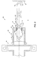
- Fig. 1 illustrates a typical continuous filter apparatus which may incorporate a self-cleaning system according to the present invention.
- Such an apparatus may be similar to that described in US 6,267,879 , the contents of which are incorporated herein in their entirety.
- the self cleaning system of the present invention may be incorporated in any suitable filtering apparatus or system, in a similar way to that described herein, mutatis mutandis.
- the continuous filter apparatus comprises an elongated tubular casing 17 having liquid inlet 1 for a connection with a liquid source that provides liquid to be filtered during filtering operation of the apparatus 10.
- the liquid inlet 1 feeds liquid from the liquid source to an annular first filtering chamber 9 that is in fluid communication with a second filtering chamber 3 via a cylindrical coarse screen 2, which is adapted for removing rough particles from the liquid.
- Pre-filtered liquid obtained downstream of the coarse screen 2 flows through a cylindrical sintered filtering element 4 to the filtered liquid chamber 12, and from there to the liquid outlet 6, which is adapted for a connection to a filtered liquid duct or reservoir (not illustrated).
- the first filtering chamber 9 and the filtered liquid chamber 12 are formed as two co-axial annular compartments within a single tubular envelope, separated one from the other by an annular bulkhead 15, which is located between the sintered filtering element 4 and the inner cylindrical surface of the tubular body 17.
- a collector manifold assembly 20 comprises an elongated collection tubing 16 substantially co-axial with the sintered filtering element 4 , and further comprises a plurality of suction arms 5 radiating from tubing 16 .
- the arms 5 are located at stations on the tubing 16 that are axially spaced with respect to axis 30 in a typically uniform manner, at a pitch P .
- one or more arms 5 may be provided, and in any case, care is taken to distribute the arms 5 circumferentially about axis 30 , and axially on axis 30 , to provide static as well as dynamic balance with respect to axis 30 .
- Each suction arm 5 comprises a suction aperture 21 that faces and is in close proximity to the inner cylindrical surface of the filter 4 , which can become clogged with filtered-out particles, and further comprises an adjacent spray nozzle 11 attached to the arm 5 .
- the suction apertures are in fluid communication with a suction source, via the hollow arms 5 and hollow tubing 16 , as will be further described herein.
- the manifold 20 is mounted for axial and rotational motion within the filter body 17 by means of suitable sliding bearing arrangements 18 , 19 , provided at the axial ends of the manifold 20 .
- the total axial displacement of the manifold 20 in any direction along axis 30 is typically similar to or grater than the pitch P , and the axial displacement for every full revolution of the manifold 20 is related to the number of arms 5 at each station, and the effective width of the suction nozzles 21 .
- the axial sliding movement in one direction is thus restricted between a minimum point at which the right-most pair of the suction apertures 21 and spraying nozzles 11 ( Fig. 1 ) is brought to the right end of the sintered filter 4 , and a maximum point at which the left-most pair of the suction members and spraying nozzles is brought to the left end of the sintered filter 4 .
- a booster-pump 13 fed with liquid taken from the filtered liquid chamber 12 , is adapted for generating a relatively high liquid pressure at the spraying nozzles 11 during operation of the cleaning system.
- a liquid stream is sprayed from each of the nozzles 11 toward the inner surface of the sintered filter 4 , vibrating the dirt sediment and particles that may be trapped within the porous filter 4 .
- liquid is sucked into the suction apertures 21 of the manifold 20 , back-washing and sweeping away the dirt from the filter 4 .
- Material sucked from the chamber 3 into the apertures 21 flow under pressure to a collection chamber 8 via drain apertures 25 that are provided at one end of the tubing 16 .
- the suction operation is generated automatically by the pressure difference that exists between the relatively high pressure liquid upstream of the filter 4 , i.e., in the second filtering chamber 3 , and free atmospheric pressure, via openings 25 the draining valves 7 , 14 , which are in open position to the atmosphere during the cleaning operation.
- a cleaning operation for the cleaning system may be activated by means of a differential pressure sensor or gauge (not illustrated) adapted for identifying a predetermined differential pressure between the final filtering chamber 3 and the filtered liquid chamber 12 , indicating that a certain amount of sediments blocks the sintered filter, thus a cleaning operation is required.
- a programmable logic controller (not illustrated) may be utilized for controlling the operation of the cleaning system for limited periods and/or according to a timer.
- the timer (not illustrated) may be adapted for activating the cleaning system periodically for preventing sedimentation in case of the filtration of a relatively clean liquid which enables the differential pressure sensor to activate the cleaning system only infrequently.
- Both, the differential pressure sensor operating mode and the timer operating mode may be by-passed by a continuous-operation-switch (not illustrated) which enables a user to selectively activate the cleaning system whenever desired, independently of the actual conditions of the filter, or the time elapsed from the previous cleaning cycle.
- a continuous-operation-switch not illustrated
- the drain apertures 25 are configured as reaction nozzles provided at the radial end of an additional pair of arms 22 that are diametrically joined to an axial portion of the tubing 16 that is within the draining chamber 8 .
- the apertures 25 are arranged in the same angular direction with respect to axis 30 .
- dirt and liquid are sucked through the apertures 21 and are ejected out of the drain nozzles 25 , which provide a reaction couple causing rotation of the manifold 20 about the axis 30 .
- the arrangement of drain nozzles 25 and arms 22 comprises a hydraulic motor, herein designated with the numeral 50 .
- Suitable liquid-driven axial reciprocation motive means according to the present invention, schematically illustrated in Fig. 1 by a dotted box 101 , provide reciprocating axial motion to the manifold 20 , typically during rotation of thereof.
- a first embodiment of the cleaning system of the present invention comprises a manifold 20 including hydraulic motor 50 as described above, and a reciprocating mechanism 150 .
- the reciprocating mechanism is coupled to the motor 50 and adapted for converting rotational motion provided by the motor 50 into reciprocating linear motion along axis 30.
- the helical motion that may be provided to the suction apertures 21 and spray nozzles 11 are powered by the hydraulic motor 50 .
- the reciprocating mechanism 150 comprises a cylindrical cam 160 axially and rigidly cantilevered at one end 162 thereof to the longitudinal end plate 35 of the drain chamber 8 .
- the cylindrical cam 160 comprises a single, endless groove 170 that comprises a clockwise helical section 172 , and a parallel but anticlockwise helical section 174 , which cross at periodic intersections 175 , and joined at their axial ends thereof by respective connecting corner intersections 178 , 179 .
- the end 32 of the conduit 16 of manifold 20 comprising the motor 50 further comprises an axial opening 36 adapted for reciprocably and rotatingly receiving the free end 164 of the cylindrical cam 160 by means of said sliding bearing arrangement 19 .
- the sliding bearing arrangement 19 comprises a suitable collar 180 mounted to said axial opening 36 .
- the inner cylindrical surface of the collar is adapted for rotation over the roller cam 160 , and further comprises a follower 182 radially projecting towards said axis 30 and engaged with respect to said grove 170 .
- the end 32 rotates about the static cylindrical cam 160 , and the follower 182 , together with the manifold 20 , is constrained to follow a path defined by the endless groove 170 , as follows.
- the follower 182 translates along groove 174 in an axial direction towards end 162 , as the follower 182 also revolves around the cam 160 , as illustrated in Fig. 3c .
- the follower 182 changes axial direction ( Fig. 3e ) and enters groove 172 , translating the follower 182 towards free end 164 , as illustrated in Fig.
- a second embodiment of the cleaning system of the present invention is similar to the arrangement described above for the first embodiment, mutatis mutandis, with the main difference that in the second embodiment the cylindrical cam, herein designated with the numeral 260 , oscillates with the manifold 20 , and the follower 282 is statically mounted to the chamber 8 .
- the cleaning system 200 comprises a manifold 20 a reciprocating mechanism 250 that is coupled to the motor 50 and adapted for converting rotational motion provided thereby into reciprocating linear motion along axis 30 .
- the reciprocating mechanism 250 comprises said cylindrical cam 260 , axially and rigidly cantilevered at one end 264 thereof to end 32 of the conduit 16 of manifold 20 comprising the motor 50 , the cam 260 comprising an endless groove 170 , as described for the first embodiment, mutatis mutandis.
- the end 35 of the chamber 8 further comprises a tubular sleeve 38 adapted for reciprocably and rotatingly receiving the free end 262 of the cylindrical cam 260 by means of said sliding bearing arrangement 19 .
- the sliding bearing arrangement 19 in this embodiment comprises a bearing 220 , the inner rotating shell of which is mounted at the end 262 , and the outer static shell being statically mounted to a sliding ring 222 , which is adapted for sliding within said sleeve 38 .
- the draining chamber 8 further comprises a suitable collar 280 statically mounted to the chamber via strut 285 .
- the inner cylindrical surface of the collar is adapted for rotation over the roller cam 260 , and further comprises a follower 282 radially projecting towards said axis 30 and engaged with respect to said grove 170 .
- the collar 280 may be mounted in the sleeve 38 .
- the collar 280 may be incorporated in the bearing arrangement 19, similar to that described for the first embodiment, mutatis mutandis.
- the end 32 rotates together with cylindrical cam 260
- the follower 282 causes the cam 260 , together with the manifold 20 , to follow a path defined by the endless groove 170, as follows.
- the cam 260 translates along groove 174 in an axial direction towards end 178 with respect to follower 282, and changes direction thereat to present groove 172 to the follower 282, translating the cam 260 back so that free end 164 approaches follower 220, in a cyclic manner, to oscillate the cam 260 with respect to the follower 282.
- the number of revolutions required for the cam 260 to travel with respect to the follower 182 , from end 179 to end 178, is related to the relative width of the suction apertures 21 with respect to the pitch P .
- a third embodiment of the cleaning system of the present invention comprises a manifold 20 including hydraulic motor 50 as described above, and a reciprocating mechanism 350.
- the reciprocating mechanism 350 is coupled to the motor 50 and adapted for converting rotational motion provided by the motor 50 into reciprocating linear motion along axis 30 .
- the helical motion that may be provided to the suction apertures 21 and spray nozzles 11 are powered by the hydraulic motor 50.
- the reciprocating mechanism 350 comprises an end cam 360 axially and rigidly mounted to end plate 35 of the drain chamber 8 .
- the end cam 360 comprises a single, endless undulating contour 370 that a number of peaks 372 smoothly joined with a number of intercalated troughs 374 , arranged in an annular manner.
- four identical troughs 374 and four identical peaks 372 are provided, and the peaks and troughs merge into one another in a substantially sinusoidal manner in the circumferential direction.
- the end cam 360 is coaxially aligned with axis 30 .
- the end 32 of the conduit 16 of manifold 20 comprising the motor 50 further comprises a shaft 340 axially mounted thereto.
- the draining chamber 8 comprises a tubular sleeve 338 statically mounted to the chamber via strut 385 .
- the sleeve 338 is adapted for reciprocably and rotatingly receiving the shaft 340 by means of said sliding bearing arrangement 19 .
- the sliding bearing arrangement 19 in this embodiment comprises a bearing 320 , the inner rotating shell of which is mounted to shaft 340 , and the outer static shell being statically mounted to a sliding ring 322 , which is adapted for sliding within said sleeve 338 .
- a sun gear 382 of a planetary gear arrangement 380 which comprises a number of planetary gears 384 mounted for rotation on planetary carrier 386 .
- the planetary carrier 386 comprises one or a number of followers 373 axially projecting therefrom towards the cam 370 .
- a spring 390 mounted to the center of the cam 360 and to the opposed center of the planetary carrier 386 , forces axial contact between the follower 373 and the cam 370 .
- the spring 390 is mounted in such a way, and/or is configured, such as not to become tangled or overwound as the planetary gear 386 revolves with respect to the cam 370 .
- the spring may be replaced by a rail arrangement that constrains the follower 373 to follow the cam 370 as it rotates about the same.
- the end 32 rotates about the static end cam 360 , and the follower 373 , together with the gear arrangement 380 and manifold 20 , is constrained to follow a path defined by the endless contour 370 , as follows.
- the follower 373 translates in an axial direction away from end 35 as the follower 373 also revolves partially around the cam 360 until it reaches the adjacent peak 372 .
- the follower 373 changes axial direction and towards end 35 as it approaches the next trough 374 .
- the number of revolutions required for the follower 373 to travel between adjacent troughs 374 , and the gear ratios of gear arrangement 380 are related to the relative width of the suction apertures 21 with respect to the pitch P .
- a fourth embodiment of the cleaning system of the present invention is similar to the arrangement described above for the third embodiment, mutatis mutandis, with the main difference that in the fourth embodiment the end cam, herein designated with the numeral 460 , oscillates together with the gear arrangement 380 , and thus with the manifold 20 , and the follower 482 is statically mounted to the end wall 35 of chamber 8 .
- the cam 460 comprises a rail arrangement 461 that constrains the follower 482 to follow the contour 480 as it revolves with respect to axis 30 . Operation of this embodiment is similar to that of the third embodiment, mutatis mutandis.
- a fifth embodiment of the cleaning system of the present invention comprises a manifold 20 including hydraulic motor 50 as described above, and a reciprocating mechanism 550 .
- the reciprocating mechanism is coupled to the motor 50 and adapted for converting rotational motion provided by the motor 50 into reciprocating linear motion along axis 30 .
- the helical motion that may be provided to the suction apertures 21 and spray nozzles 11 are powered by the hydraulic motor 50 .
- the reciprocating mechanism comprises a rail 560 of substantially rectangular cross-section axially and rigidly cantilevered at one end 562 thereof to end plate 35 of the drain chamber 8 .
- the end 32 of the conduit 16 of manifold 20 comprising motor 50 further comprises an axial opening 36 adapted for reciprocably and rotatingly receiving the free end 564 of the rail 560 by means of sliding bearing arrangement 19 .
- the sliding bearing arrangement comprises a suitable collar 580 mounted to said axial opening via bearing 585 .
- the collar 580 comprises an inner rectangular opening and sliding guides 586 for sliding the collar axially along the said rail 560 , and an outer typically cylindrical surface for connection to the inner race of the bearing 585 which remains static when the outer race of the bearing rotates with the manifold 20 .
- the outer race of the bearing 585 is fixed to the axial opening 36 .
- the reciprocating mechanism 550 further comprises a shuttle mechanism 570 , in the form of a frame 575 comprising two drive rollers 572, 573 rotatingly mounted thereto, and used alternately for driving the shuttle in one direction or the other along the rail 560.
- a shuttle mechanism 570 in the form of a frame 575 comprising two drive rollers 572, 573 rotatingly mounted thereto, and used alternately for driving the shuttle in one direction or the other along the rail 560.
- Each of the drive rollers 572, 573 is axially mounted to a gear wheel 582, 583, respectively.
- the frame 575 is connected to the collar 580 .
- the upper surface of the rail 560 may comprise a rack, and the drive rollers 572, 573 replaced with drive pinions for better traction of the shuttle 570 with respect to the rail 560.
- the rail may be of circular section, for example, and the rollers are appropriately shaped to enable rolling over a convex cylindrical surface.
- the shuttle 570 may further comprise additional loose guide rollers 564 mounted on the frame 575 for free rotation with respect to the lower and vertical surfaces of the rail.
- a plate 585 is pivotably mounted to the frame 575 at pivot 589 .
- the plate 585 can pivot about pivot 589 about a pivot arc between two end positions, defined by a stop pin 576 mounted to plate 585 and sliding in an arcuate guide slot 577 in frame 575 .
- a first gear wheel 581 is rotatingly mounted to the plate at pivot 589 , and is in mesh with a gear wheel 586 via intermediate gear wheels 587 and 588 , all of which are carried by the plate 585 .
- Wheels 586 and 587 are centered on an arch of constant radius about pivot 589 , and wheels 581, 588 and 587 have their centers rectilinearly aligned.
- Wheels 586 and 587 have the same pitch diameter, and the said pivot arc of the plate 585 is such that in either of the end positions, one or the other of wheels 586 and 587 meshes with one or the other of gear wheels 582, 583, respectively.
- wheels 581 and 587 could be engaged one with the other by means of a belt, rather than wheel 588 , mutatis mutandis.
- the end 32 further comprises an internal gear 590 which meshes with gear wheel 592 carried on frame 575 .
- a worm gear 594 axially connected to wheel 592 meshes with wheel 581 .
- the shuttle 570 further comprises a toggle mechanism ' 595 for changing direction thereof between two axially distanced stops 578, 579 mounted in the drain chamber 8 .
- the toggle mechanism 595 comprises an arm 596 fixed to plate 585 and radially extending from pivot 589 such as to engage with one or another of stops 578, 579 when the shuttle 570 reaches one or another of the axial end positions thereof.
- the end 32 rotates about the rail 560 , and the shuttle 570 , together with the collar 580 and manifold 20 , is constrained to follow a reciprocating path with respect to the rail 560 as follows.
- the arm 596 is pressed against stop 578 such as to pivot the plate 585 to the position illustrated in Fig. 9 , so that wheel 587 is meshed with wheel 583 , and wheel 586 is disengaged from wheel 582 .
- the rotation of the manifold 20 causes wheel 581 to turn in a counterclockwise direction by virtue of internal gear 590 , wheel 592 and worm gear 594 .
- wheel 581 turns wheel 583 in a clockwise direction, via wheels 588 and 587 , which rotates drive roller 573 , translating the shuttle 570 towards the end plate 35 .
- arm 596 presses against the stop 579 , and the momentum of the shuttle 570 carries the same a little further such as to pivot the arm 579 to the position illustrated in Fig. 8 .
- wheel 586 is meshed with wheel 582 , and wheel 587 is disengaged from wheel 583 .
- the number of revolutions required for the shuttle 570 to travel between stops 578, 579, and the gear ratios provided by gears 590, 592, 594, 581, 588, 587, 588, 582 583, are related to the relative width of the suction apertures 21 with respect to the pitch P .
- rotation power may be provided by non-liquid based power sources, for example an electric motor, and the rotational power used for providing reciprocating axial motion in a similar manner to that described above, mutatis mutandis.
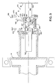
- a sixth embodiment of the cleaning system of the present invention comprises a manifold 20 including hydraulic motor 50 as described above, and a reciprocating mechanism 650 .
- the reciprocating mechanism 650 may operate independently of the motor 50 , and in fact the system may actually operate without the need for the rotational motor 50 .
- the arms 5 are connected at their radial ends to an annular collector (not shown) and the suction openings 21 may be in the form of a circumferential slit opposite to the inner cylindrical surface of the filter, or in the form of circumferentially-located closely-spaced discrete openings.
- annular collector not shown
- such an embodiment does not require the filter 4 to be cylindrical, and in fact the filter can have any cross-sectional shape, for example square, so long as the aforementioned "annular" collector comprises a complementary shape such that the suction openings, now in the form of a peripheral slit, are opposite to the inner surface of the filter.
- the reciprocating mechanism is advantageously coupled with the motor 50 , and the combination is thus adapted for providing rotational motion and concurrent reciprocating linear motion along axis 30 .
- the helical motion that may be provided to the suction apertures 21 and spray nozzles 11 are powered by the hydraulic motor 50 and reciprocating mechanism 650 .
- a cylindrical shaft 660 is axially and rigidly cantilevered at one end 664 thereof to end 32 of the conduit 16 of manifold 20 comprising the motor 50 .
- the end 35 of the chamber 8 further comprises a tubular sleeve 38 adapted for reciprocably and rotatingly receiving the free end 662 of the shaft 660 by means of said sliding bearing arrangement 19 .
- the sliding bearing arrangement 19 in this embodiment comprises a bearing 620 , the inner rotating shell of which is mounted at the end 662 , and the outer static shell being statically mounted to a sliding ring 622 , which is adapted for sliding within said sleeve 38 .
- the reciprocation mechanism 650 comprises a linear dual-direction fluid motor 660, in the form of a plurality of arms 665 radially projecting from the end 32 of the conduit 16 of manifold 20 .
- a bi-directional nozzle 670 is provided, having two separate fluid passages 672, 677, each of which has an inlet, 673, 678, respectively, and an outlet, 674, 679, respectively.
- the inlets 673, 678 are coplanar, and each can be alternately aligned with the mouth 667 at the free end of the arm 665 by sliding the nozzle 670 axially along rail 680 in one direction or the other.
- the rail 680 comprises blanks 684, 685 for blocking the one or other of the inlets 673, 678, respectively, when the other inlet is aligned with the mouth 667 .
- the outlets 674, 679 are aligned parallel to axis 30 , but in axially opposed directions.
- the nozzle 670 further comprises a tab arrangement 690 that alternately cooperates with one or another of a pair of spaced annular stop rings 610, 620 in chamber 8 to axially displace the nozzle 670 to a position in which one or another of the inlets 673, 678 is aligned with mouth 667 .
- the tab arrangement 690 preferably comprises a free rolling wheel 695 that is mounted to the radial end of nozzle 670 , with the axis of rotation radially aligned with respect to axis 30 .
- the wheel 695 comprises a tread surface 696 adapted for alternate contact with one or the other of said rings 610, 620 .
- a reaction force propels the manifold 20 in an axial direction towards end 35 , at the same time as the manifold is rotating by virtue of the action of motor 50 .
- wheel 695 presses against the stop 620 , and the momentum of the manifold 20 may carry the same a little further, such as to slide the nozzle 670 back to the position illustrated in Fig. 11 .
- the linear motor 660 may be adapted to operate such that the outlets 674, 679, or another part of the nozzle 670 alternately cooperates with the ring stops 610, 620, and in such a case the tab arrangement 690 is not required and may be dispensed with.
- nozzles 670 it is possible to slidingly mount the nozzles 670 to the arms 22 of the motor 50 , by modifying the radial ends of the arms in a similar manner to that described for the radial ends of arms 665 , mutatis mutandis.
- Such a modification to the sixth embodiment requires less parts overall, and shortens the axial dimension of the self-cleaning system.
- the tangential nozzles 25 may be incorporated in the nozzle 670 , and in fact each one of the said passages 672, 677 may comprise a said tangential nozzle 25 aligned in the same direction.
- a seventh embodiment of the cleaning system of the present invention is similar to the arrangement described above for the sixth embodiment, mutatis mutandis, with the following differences.
- the rotational motor 50 and the linear motor 660 may be further combined such that arms 22 ' of the combined motor 630 each comprise a vectored nozzle arrangement 670 ' that provides a jet of liquid providing a reaction force component in the tangential direction T for providing rotation, and reaction force component in the axial direction A for providing axial displacement.
- the nozzle 670' comprises two separate fluid passages 672 ', 677' , each of which has an inlet, 673' , 678' , similar in construction and operation with respect to rail 680 as described with respect to the embodiment illustrated in Figs. 13 and 14 , mutatis mutandis.
- the respective outlets 674' , 679' are aligned with their axes 615 at angles + ⁇ and - ⁇ to the tangential direction T , so that each nozzle may provide (in turn) a tangential reaction force component in the same tangential direction T , and an axial reaction force component parallel to axis 30 , but in axially opposed directions.
- the nozzle 670' further comprises a tab arrangement 690' similar to that described in connection with tab 690 of the sixth embodiment, mutatis mutandis.
- a tab arrangement 690' similar to that described in connection with tab 690 of the sixth embodiment, mutatis mutandis.
- the nozzle 670' is displaced so that inlet 677 ' is blocked, and inlet 673' is aligned with mouth 667' of arm 22' .
- the action of the liquid exiting passage 672' provides a reaction force that continues to turn the manifold 20 about axis 30 , and that propels the same towards the end 35 .
- rotational motion may be provided by a liquid turbine arrangement, for example, and the rotational power coupled to a reciprocating axial motion in a similar manner to that described above, mutatis mutandis.
Landscapes
- Chemical & Material Sciences (AREA)
- Chemical Kinetics & Catalysis (AREA)
- Filtration Of Liquid (AREA)
- Filtering Of Dispersed Particles In Gases (AREA)
- Lubrication Details And Ventilation Of Internal Combustion Engines (AREA)
- Cleaning By Liquid Or Steam (AREA)
Applications Claiming Priority (1)
| Application Number | Priority Date | Filing Date | Title |
|---|---|---|---|
| US11/843,710 US20090050582A1 (en) | 2007-08-23 | 2007-08-23 | Self-Cleaning System For Filter |
Publications (2)
| Publication Number | Publication Date |
|---|---|
| EP2027905A2 true EP2027905A2 (fr) | 2009-02-25 |
| EP2027905A3 EP2027905A3 (fr) | 2009-04-08 |
Family
ID=40042748
Family Applications (1)
| Application Number | Title | Priority Date | Filing Date |
|---|---|---|---|
| EP08013212A Withdrawn EP2027905A3 (fr) | 2007-08-23 | 2008-07-22 | Système autonettoyant pour filtre |
Country Status (5)
| Country | Link |
|---|---|
| US (1) | US20090050582A1 (fr) |
| EP (1) | EP2027905A3 (fr) |
| AU (1) | AU2008203009A1 (fr) |
| BR (1) | BRPI0804173A2 (fr) |
| RU (1) | RU2008130142A (fr) |
Cited By (13)
| Publication number | Priority date | Publication date | Assignee | Title |
|---|---|---|---|---|
| WO2012046240A3 (fr) * | 2010-10-07 | 2012-07-05 | Amiad Water Systems Ltd. | Unité et système de filtration de fluide |
| EP2527021A1 (fr) * | 2011-05-23 | 2012-11-28 | Odis Irrigation Equipment Limited | Système de filtration possédant des capacités de lavage à contre-courant |
| WO2013022441A1 (fr) * | 2011-08-10 | 2013-02-14 | Gita Green, Llc | Appareil et procédé pour le nettoyage de filtres à air |
| US8668782B2 (en) | 2011-08-10 | 2014-03-11 | Gita Green, Llc | Apparatus and method for cleaning air filters |
| EP2834017A2 (fr) * | 2012-04-04 | 2015-02-11 | Sea-Lix AS | Nettoyage de filtre |
| USD765322S1 (en) | 2011-08-10 | 2016-08-30 | Gita Green, Inc. | Apparatus for cleaning air filters |
| US9480941B2 (en) | 2007-10-29 | 2016-11-01 | Gita Green, Inc. | Apparatus and method for cleaning air filters |
| US9718014B2 (en) | 2012-10-31 | 2017-08-01 | Gita Green, Inc. | Device and method for cleaning bag filters |
| CN111888827A (zh) * | 2020-03-26 | 2020-11-06 | 新疆水利水电科学研究院 | 泵前无压往复轴式自清洗滤网过滤装置 |
| EP3710130A4 (fr) * | 2017-11-19 | 2020-12-23 | Oded Shamir | Appareil et/ou procédé de filtration |
| CN113476928A (zh) * | 2021-05-25 | 2021-10-08 | 张齐鲁 | 一种可反冲洗的不锈钢管式多层烧结滤网精密过滤装置 |
| CN116492740A (zh) * | 2023-06-25 | 2023-07-28 | 山西农业大学山西功能食品研究院 | 一种黄花菜发酵加工除杂装置 |
| US11724225B2 (en) | 2019-06-26 | 2023-08-15 | Gita Green, Inc. | Filtering medium cleaning apparatus and method |
Families Citing this family (15)
| Publication number | Priority date | Publication date | Assignee | Title |
|---|---|---|---|---|
| DE102006050127A1 (de) * | 2006-10-25 | 2008-04-30 | Ets Trade S.A.R.L. | Filtervorrichtung |
| US20090294340A1 (en) * | 2008-03-06 | 2009-12-03 | Gene Hirs | Pressure filter for processing a large volume of fluid with automatic backwashing by linear and rotation of the backwash tube |
| US8647516B2 (en) * | 2010-09-03 | 2014-02-11 | Johnny Leon LOVE | Filtration method with self-cleaning filter assembly |
| US20140021125A1 (en) * | 2012-07-18 | 2014-01-23 | Dan Lin | Self-cleaning suction filter |
| US9561454B2 (en) | 2012-10-09 | 2017-02-07 | Ovivo Inc. | Debris filter with splitter bar |
| WO2015038079A1 (fr) * | 2013-09-12 | 2015-03-19 | Antel Aritma Tesi̇sleri̇ İnşaat Sanayi̇ Ve Ti̇caret Anoni̇m Şi̇rketi̇ | Filtre de nettoyage automatique de brosse de tuyère ayant un motoréducteur |
| US20160310876A1 (en) * | 2013-12-04 | 2016-10-27 | Amiad Water Systems Ltd. | Filtration system and filter assembly associated therewith |
| EP3000517B1 (fr) | 2014-09-19 | 2018-01-03 | Sati S.r.l. | Filtre autonettoyant |
| CN104801091A (zh) * | 2015-04-22 | 2015-07-29 | 杜卫卫 | 一种利用新能源提供动力的化工废水处理装置 |
| US11083985B2 (en) * | 2017-01-20 | 2021-08-10 | Andritz Inc. | Vapor relief strainer with cleaner |
| IT201700076873A1 (it) | 2017-07-07 | 2019-01-07 | Alfa Water S R L | Filtro autopulente |
| IT201800003030A1 (it) | 2018-02-26 | 2019-08-26 | Serenambiente S R L | Filtro autopulente |
| CN108404482A (zh) * | 2018-04-28 | 2018-08-17 | 深圳市绿洲彩虹机电科技有限公司 | 水动力自清洁过滤器 |
| NO345889B1 (en) * | 2020-02-19 | 2021-09-27 | Tenko As | Filter systems and methods |
| CN112169397A (zh) * | 2020-10-28 | 2021-01-05 | 未来都市(苏州工业园区)规划建筑设计事务所有限公司 | 一种人工湿地系统 |
Citations (6)
| Publication number | Priority date | Publication date | Assignee | Title |
|---|---|---|---|---|
| US4157251A (en) | 1978-01-06 | 1979-06-05 | Interfiltre, S. A. | Self-cleaning filter device |
| US5228993A (en) | 1990-02-09 | 1993-07-20 | Mordeki Drori | Cleanable filter system with longitudinally movable and rotatable cleaning member |
| US5268095A (en) * | 1990-06-06 | 1993-12-07 | Filtration Ltd. | Self-cleaning filter |
| US5871652A (en) * | 1995-08-04 | 1999-02-16 | Pipetronics, Inc. | Method for high volume pipeline water filtration |
| WO2005110576A1 (fr) | 2004-05-03 | 2005-11-24 | Olson Irrigation Systems | Filtre et appareil de nettoyage de filtre et méthodes associées |
| EP1785178A1 (fr) | 2005-11-14 | 2007-05-16 | Odis Irrigation Equipment Limited | Procede de nettoyage d'un systeme de filtration et un systeme de filtration ayant un dispositif de nettoyage |
Family Cites Families (2)
| Publication number | Priority date | Publication date | Assignee | Title |
|---|---|---|---|---|
| US3568414A (en) * | 1969-06-05 | 1971-03-09 | Donaldson Co Inc | Cleaning apparatus for fluid filters |
| US6267879B1 (en) * | 1999-08-11 | 2001-07-31 | Odis Irrigation Equipment Ltd. | Continuous liquid filtering apparatus with multi-layer sintered filtering element |
-
2007
- 2007-08-23 US US11/843,710 patent/US20090050582A1/en not_active Abandoned
-
2008
- 2008-07-08 AU AU2008203009A patent/AU2008203009A1/en not_active Abandoned
- 2008-07-09 RU RU2008130142/15A patent/RU2008130142A/ru not_active Application Discontinuation
- 2008-07-15 BR BRPI0804173-3A patent/BRPI0804173A2/pt not_active Application Discontinuation
- 2008-07-22 EP EP08013212A patent/EP2027905A3/fr not_active Withdrawn
Patent Citations (6)
| Publication number | Priority date | Publication date | Assignee | Title |
|---|---|---|---|---|
| US4157251A (en) | 1978-01-06 | 1979-06-05 | Interfiltre, S. A. | Self-cleaning filter device |
| US5228993A (en) | 1990-02-09 | 1993-07-20 | Mordeki Drori | Cleanable filter system with longitudinally movable and rotatable cleaning member |
| US5268095A (en) * | 1990-06-06 | 1993-12-07 | Filtration Ltd. | Self-cleaning filter |
| US5871652A (en) * | 1995-08-04 | 1999-02-16 | Pipetronics, Inc. | Method for high volume pipeline water filtration |
| WO2005110576A1 (fr) | 2004-05-03 | 2005-11-24 | Olson Irrigation Systems | Filtre et appareil de nettoyage de filtre et méthodes associées |
| EP1785178A1 (fr) | 2005-11-14 | 2007-05-16 | Odis Irrigation Equipment Limited | Procede de nettoyage d'un systeme de filtration et un systeme de filtration ayant un dispositif de nettoyage |
Cited By (20)
| Publication number | Priority date | Publication date | Assignee | Title |
|---|---|---|---|---|
| US9480941B2 (en) | 2007-10-29 | 2016-11-01 | Gita Green, Inc. | Apparatus and method for cleaning air filters |
| US9347570B2 (en) | 2010-10-07 | 2016-05-24 | Amiad Water Systems Ltd | Fluid filtering unit and system |
| WO2012046240A3 (fr) * | 2010-10-07 | 2012-07-05 | Amiad Water Systems Ltd. | Unité et système de filtration de fluide |
| EP2527021A1 (fr) * | 2011-05-23 | 2012-11-28 | Odis Irrigation Equipment Limited | Système de filtration possédant des capacités de lavage à contre-courant |
| WO2013022441A1 (fr) * | 2011-08-10 | 2013-02-14 | Gita Green, Llc | Appareil et procédé pour le nettoyage de filtres à air |
| US8668782B2 (en) | 2011-08-10 | 2014-03-11 | Gita Green, Llc | Apparatus and method for cleaning air filters |
| AU2011374873B2 (en) * | 2011-08-10 | 2015-07-16 | Gita Green, Inc. | Apparatus and method for cleaning air filters |
| USD765322S1 (en) | 2011-08-10 | 2016-08-30 | Gita Green, Inc. | Apparatus for cleaning air filters |
| US9718015B2 (en) | 2011-08-10 | 2017-08-01 | Gita Green, Inc. | Apparatus and method for cleaning air filters |
| EP2834017B1 (fr) * | 2012-04-04 | 2021-11-10 | MossHydro AS | Nettoyage de filtre |
| EP2834017A2 (fr) * | 2012-04-04 | 2015-02-11 | Sea-Lix AS | Nettoyage de filtre |
| US9718014B2 (en) | 2012-10-31 | 2017-08-01 | Gita Green, Inc. | Device and method for cleaning bag filters |
| EP3710130A4 (fr) * | 2017-11-19 | 2020-12-23 | Oded Shamir | Appareil et/ou procédé de filtration |
| US11724225B2 (en) | 2019-06-26 | 2023-08-15 | Gita Green, Inc. | Filtering medium cleaning apparatus and method |
| CN111888827A (zh) * | 2020-03-26 | 2020-11-06 | 新疆水利水电科学研究院 | 泵前无压往复轴式自清洗滤网过滤装置 |
| CN111888827B (zh) * | 2020-03-26 | 2022-05-24 | 新疆水利水电科学研究院 | 泵前无压往复轴式自清洗滤网过滤装置 |
| CN113476928A (zh) * | 2021-05-25 | 2021-10-08 | 张齐鲁 | 一种可反冲洗的不锈钢管式多层烧结滤网精密过滤装置 |
| CN113476928B (zh) * | 2021-05-25 | 2022-08-16 | 唐山奥名机械设备制造有限公司 | 一种可反冲洗的不锈钢管式多层烧结滤网精密过滤装置 |
| CN116492740A (zh) * | 2023-06-25 | 2023-07-28 | 山西农业大学山西功能食品研究院 | 一种黄花菜发酵加工除杂装置 |
| CN116492740B (zh) * | 2023-06-25 | 2023-08-25 | 山西农业大学山西功能食品研究院 | 一种黄花菜发酵加工除杂装置 |
Also Published As
| Publication number | Publication date |
|---|---|
| EP2027905A3 (fr) | 2009-04-08 |
| BRPI0804173A2 (pt) | 2009-06-16 |
| RU2008130142A (ru) | 2010-01-20 |
| AU2008203009A1 (en) | 2009-03-12 |
| US20090050582A1 (en) | 2009-02-26 |
Similar Documents
| Publication | Publication Date | Title |
|---|---|---|
| EP2027905A2 (fr) | Système autonettoyant pour filtre | |
| AU768447B2 (en) | Continuous liquid filtering apparatus having a multi-layer sintered filtering element with electromechanical self-cleaning system | |
| KR101450017B1 (ko) | 여과포를 세정하기 위한 장치 및 방법 | |
| CN101351254B (zh) | 清洗设备 | |
| FI92800B (fi) | Itsestään puhdistuva suodatin | |
| US6596166B1 (en) | Apparatus for cleaning a filter cloth in a filtering device | |
| CN104128032B (zh) | 反冲洗过滤器 | |
| EP3597283B1 (fr) | Agencement de filtre | |
| GB2500900A (en) | Filter cleaning | |
| CN209221638U (zh) | 一种水资源生态修复装置 | |
| KR102105123B1 (ko) | 필터 세척장치 | |
| CN108744741B (zh) | 一种汽车空调过滤芯清洗装置 | |
| CN212944330U (zh) | 一种滚筒式洗药机 | |
| CN113350859A (zh) | 一种一体化污水处理设备 | |
| CN221693050U (zh) | 一种提高效率的污水处理沉淀池 | |
| CN104014178A (zh) | 一种自动反冲洗润滑油过滤装置 | |
| CN118203895A (zh) | 一种制药工业废水净化装置及使用方法 | |
| KR20110020458A (ko) | 양방향 이물질 배출부를 갖는 디스크 필터 | |
| CN220214158U (zh) | 一种用于环境治理污水处理设备 | |
| CN219083322U (zh) | 一种新型空气净化器设备 | |
| CN211386020U (zh) | 一种铝环生产用清洗装置 | |
| CN115540150A (zh) | 一种负离子空气净化系统 | |
| CN115784401A (zh) | 一种防堵塞的城市污水处理装置 | |
| CN118255421A (zh) | 一种采用管式膜的废水处理装置 | |
| CN114225592A (zh) | 一种自清洗环保型烟尘过滤机 |
Legal Events
| Date | Code | Title | Description |
|---|---|---|---|
| PUAI | Public reference made under article 153(3) epc to a published international application that has entered the european phase |
Free format text: ORIGINAL CODE: 0009012 |
|
| AK | Designated contracting states |
Kind code of ref document: A2 Designated state(s): AT BE BG CH CY CZ DE DK EE ES FI FR GB GR HR HU IE IS IT LI LT LU LV MC MT NL NO PL PT RO SE SI SK TR |
|
| AX | Request for extension of the european patent |
Extension state: AL BA MK RS |
|
| PUAL | Search report despatched |
Free format text: ORIGINAL CODE: 0009013 |
|
| AK | Designated contracting states |
Kind code of ref document: A3 Designated state(s): AT BE BG CH CY CZ DE DK EE ES FI FR GB GR HR HU IE IS IT LI LT LU LV MC MT NL NO PL PT RO SE SI SK TR |
|
| AX | Request for extension of the european patent |
Extension state: AL BA MK RS |
|
| 17P | Request for examination filed |
Effective date: 20091006 |
|
| 17Q | First examination report despatched |
Effective date: 20091030 |
|
| AKX | Designation fees paid |
Designated state(s): AT BE BG CH CY CZ DE DK EE ES FI FR GB GR HR HU IE IS IT LI LT LU LV MC MT NL NO PL PT RO SE SI SK TR |
|
| GRAP | Despatch of communication of intention to grant a patent |
Free format text: ORIGINAL CODE: EPIDOSNIGR1 |
|
| STAA | Information on the status of an ep patent application or granted ep patent |
Free format text: STATUS: THE APPLICATION IS DEEMED TO BE WITHDRAWN |
|
| 18D | Application deemed to be withdrawn |
Effective date: 20120926 |