EP2027490B1 - Anordnung mit einer medizinischen gammasonde, optisches modul und bausatz - Google Patents
Anordnung mit einer medizinischen gammasonde, optisches modul und bausatz Download PDFInfo
- Publication number
- EP2027490B1 EP2027490B1 EP07722421A EP07722421A EP2027490B1 EP 2027490 B1 EP2027490 B1 EP 2027490B1 EP 07722421 A EP07722421 A EP 07722421A EP 07722421 A EP07722421 A EP 07722421A EP 2027490 B1 EP2027490 B1 EP 2027490B1
- Authority
- EP
- European Patent Office
- Prior art keywords
- gamma probe
- optical module
- light source
- medical gamma
- medical
- Prior art date
- Legal status (The legal status is an assumption and is not a legal conclusion. Google has not performed a legal analysis and makes no representation as to the accuracy of the status listed.)
- Not-in-force
Links
- 230000003287 optical effect Effects 0.000 title claims abstract description 44
- 238000001514 detection method Methods 0.000 claims abstract description 5
- 239000000523 sample Substances 0.000 claims description 52
- 230000000694 effects Effects 0.000 claims description 13
- 238000010276 construction Methods 0.000 claims 1
- 210000001519 tissue Anatomy 0.000 description 13
- 210000001165 lymph node Anatomy 0.000 description 4
- 238000005259 measurement Methods 0.000 description 4
- 206010028980 Neoplasm Diseases 0.000 description 3
- 230000005855 radiation Effects 0.000 description 3
- 230000001419 dependent effect Effects 0.000 description 2
- 238000011161 development Methods 0.000 description 2
- 238000009420 retrofitting Methods 0.000 description 2
- 230000035945 sensitivity Effects 0.000 description 2
- 230000003595 spectral effect Effects 0.000 description 2
- 206010006187 Breast cancer Diseases 0.000 description 1
- 208000026310 Breast neoplasm Diseases 0.000 description 1
- 201000009030 Carcinoma Diseases 0.000 description 1
- 241001446467 Mama Species 0.000 description 1
- 208000000453 Skin Neoplasms Diseases 0.000 description 1
- 230000003187 abdominal effect Effects 0.000 description 1
- 230000006978 adaptation Effects 0.000 description 1
- 208000035250 cutaneous malignant susceptibility to 1 melanoma Diseases 0.000 description 1
- 238000013461 design Methods 0.000 description 1
- 229940079593 drug Drugs 0.000 description 1
- 239000003814 drug Substances 0.000 description 1
- 238000005516 engineering process Methods 0.000 description 1
- 230000010354 integration Effects 0.000 description 1
- 230000004807 localization Effects 0.000 description 1
- 201000001441 melanoma Diseases 0.000 description 1
- 238000000034 method Methods 0.000 description 1
- 230000002285 radioactive effect Effects 0.000 description 1
- 238000000163 radioactive labelling Methods 0.000 description 1
- 239000012217 radiopharmaceutical Substances 0.000 description 1
- 238000005070 sampling Methods 0.000 description 1
- 210000005005 sentinel lymph node Anatomy 0.000 description 1
- 201000000849 skin cancer Diseases 0.000 description 1
- 238000010561 standard procedure Methods 0.000 description 1
Images
Classifications
-
- G—PHYSICS
- G01—MEASURING; TESTING
- G01T—MEASUREMENT OF NUCLEAR OR X-RADIATION
- G01T1/00—Measuring X-radiation, gamma radiation, corpuscular radiation, or cosmic radiation
- G01T1/16—Measuring radiation intensity
- G01T1/161—Applications in the field of nuclear medicine, e.g. in vivo counting
- G01T1/164—Scintigraphy
- G01T1/1641—Static instruments for imaging the distribution of radioactivity in one or two dimensions using one or several scintillating elements; Radio-isotope cameras
- G01T1/1648—Ancillary equipment for scintillation cameras, e.g. reference markers, devices for removing motion artifacts, calibration devices
Definitions
- the invention relates to an arrangement with a medical gamma probe and a kit with a medical gamma probe and an optical module.
- the radioactive labeling of the first draining lymph node, (sentinel lymph node or sentinel node), in an operation (OP) of malignant melanoma (skin cancer) and ma carcinoma (breast cancer) and some cancers in the cervical and abdominal area has already become one in medical practice Standard method developed.
- OP operation
- malignant melanoma skin cancer
- ma carcinoma breast cancer
- some cancers in the cervical and abdominal area has already become one in medical practice Standard method developed.
- the use of radiolabeled, tumor-specific drugs is becoming increasingly important in the direct localization of tumorous tissue due to the expected high local resolution.
- the technical characteristics and the handling of the gamma probes used to localize the radioactively marked areas of the tissue significantly affect the quality as well as the duration of the lymph node or tumor search.
- the document EP 0 999 457 A1 discloses a medical device for measuring the radiation of radiopharmaceutical agents.
- the object of the invention is to provide improved technologies for a medical gamma probe, with which the ease of use for the user of the medical gamma probe is increased. Disadvantages of the previous gamma probe technique should be avoided.
- the light source controller may be configured to adjust the light intensity of the light beams emitted from the light source in proportion to the detected activity, it being understood that a suitable proportionality factor may be taken into account.
- a preferred embodiment of the invention provides that the optical module is detachably mounted on the medical gamma probe.
- the solubility of the optical module can be carried out, for example, with a plug connection or a screw connection.
- the optical module is integrated in a housing of the medical gamma probe.
- a uniform housing can be created.
- a detachable mounting of the optical module is possible, for example by means of a removable or openable housing section, which allows the removal or attachment of the optical module.
- a housing section can be designed to be pivotable.
- An advantageous embodiment of the invention provides that the light source is arranged in a central region of a collimator. As a result, the effort for a central guidance of the light beams generated by the light source is reduced, since the light source itself is already positioned in the central region of the collimator. In this embodiment, a concentric distribution of the light beams about the central region of the collimator is made particularly easy.
- a development of the invention provides that the optical module is formed in an additional collimator placed on the medical gamma probe.
- the additional collimator may be plugged or screwed onto a detection-side end of the medical gamma probe.
- other types of attachment of additional collimator to the medical Gamma probes can be provided, in particular also for retrofitting the additional collimator.
- the optical module comprises one or more optical elements which are configured to direct the light beams and optionally to change.
- a change in the light beams may in particular also include a focusing of the light beams or also a scattering of these or a combination thereof.
- a development of the invention may provide that the one or more optical elements are configured to guide the light beams substantially collinear with the longitudinal axis of a gamma probe tip of the medical gamma probe.
- medical gamma probes are designed so that a preferred detection direction is formed substantially collinear to the longitudinal extent of the probe.
- the light source is formed with one or more light-emitting diodes or one or more laser diodes.
- a combination of light emitting diodes (LED) and laser diodes may also be provided.
- the diodes preferably have a focused radiation, a high quantum efficiency and / or a long lifetime.
- An adaptation to the spectral sensitivity curve of the human eye is provided by using a light source which generates light in a spectral range in which the human eye is particularly sensitive, in particular green light.
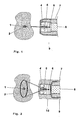
- Fig. 1 12 shows a schematic representation of a head-side or detection-side section 20 of a medical gamma probe with an optical module 4 formed therein, which can also be referred to as an optical light pointer module, so that a light-beam-assisted gamma probe is provided.
- the medical gamma probe in turn can be basically of any design.
- the optical module 4 makes it possible to generate an optical pointer.
- the optical module 4 has one or more light sources 6 and associated optical elements 5 to guide light beams generated by the light source 6 and optionally to influence, for example, to focus.
- the light source 6 in particular, a high-luminous light-emitting diode or a laser diode can be provided.
- the optical pointer is a direct display of a tissue section 1, which is radioactively marked, allows. During the activity measurement with the medical gamma probe, the tissue area 1 with the maximum activity can be directly marked light-optically.
- the optical module 4 is arranged in the region of a probe head 21, which in turn has a collimator 9 and a scintillation detector 8.
- the optical module 4 is fixedly mounted on a housing 7 of the medical gamma probe 20. This can be done outside of the housing 7 or, as this Fig. 1 shows, by integration take place in the collimator 9.
- the light source 6 is arranged in the central region of the collimator 9. The light beams generated by the light source 6 form a marking light spot 2 at the center of highest activity on the tissue section 1, thereby directly and accurately displaying to the user a tissue sampling point.
- the shape of the light spot 2 is determined by the associated optical element 5 and is preferably a cross, a circle (see. Fig. 2 ), a point or a combination of these or other geometries.
- a distance-dependent and likewise circular sensitivity range of a measurement window of the medical gamma probe can be additionally projected onto the tissue section, so that an entire tissue area is identified, which contributes to a current measured value of the medical gamma probe.
- the light spot 2 then indicates with maximum intensity the position of a point in the tissue section 1 with maximum activity.
- the light-optical display of the maximum measured activity of the medical gamma probe can be additionally supported by the maximum light intensity of the light source 6, by the maximum pulse frequency of the light spot 2, a color change or a combination thereof.
- the light spot 2 can also display the position of a measuring area in the tissue section 1 continuously or in pulsed form, independently of the measured activity of the medical gamma probe.
- Fig. 2 shows a schematic representation of a head-side portion 20 of a medical gamma probe, on which the optical module 4 is placed.
- a circular light spot 3 is shown.
- the optical module 4 is formed as a supplementary component, which is also suitable for retrofitting and which is integrated in the illustrated embodiment in an attachable additional collimator 10.
- An independent embodiment of the optical module 4 can also be provided, so that it can be detachably mounted, for example by means of plugging or screwing.
Landscapes
- Physics & Mathematics (AREA)
- Health & Medical Sciences (AREA)
- Engineering & Computer Science (AREA)
- Biomedical Technology (AREA)
- General Health & Medical Sciences (AREA)
- Medical Informatics (AREA)
- Nuclear Medicine, Radiotherapy & Molecular Imaging (AREA)
- Optics & Photonics (AREA)
- Life Sciences & Earth Sciences (AREA)
- General Physics & Mathematics (AREA)
- High Energy & Nuclear Physics (AREA)
- Molecular Biology (AREA)
- Spectroscopy & Molecular Physics (AREA)
- Nuclear Medicine (AREA)
Abstract
Description
- Die Erfindung bezieht sich auf eine Anordnung mit einer medizinischen Gammasonde und einen Bausatz mit einer medizinischen Gammasonde und einem optischen Modul.
- Das radioaktive Markieren des ersten dränierenden Lymphknoten, (Wächterlymphknoten oder Sentinel Node), bei einer Operation (OP) des malignen Melanoms (Hautkrebs) und des Mamakarzinioms (Brustkrebs) sowie einiger Krebsarten im Hals- und Bauchbereich hat sich in der medizinischen Praxis bereits zu einer Standardmethode entwickelt. Darüber hinaus gewinnt die Anwendung radioaktiv markierter, tumorspezifischer Pharmaka wegen der zu erwartenden hohen Ortauflösung bei der direkten Lokalisation tumorösen Gewebes zunehmend an Bedeutung. Von den technischen Eigenschaften und der Handhabung der zur Lokalisation der radioaktiv markierten Gewebebereiche verwendeten Gammasonden hängt sowohl die Qualität als auch die Dauer der Lymphknoten- oder Tumorsuche ganz wesentlich ab.
- Das Auffinden radioaktiv markierter Lymphknoten mit Hilfe von bekannten Gammasonden findet üblicherweise durch eine ortsauflösende Aktivitätsmessung statt. Hierbei erfolgt im Bereich des Aktivitätsmaximums die örtliche Zuordnung und damit letztlich das Auffinden des Lymphknotens durch eine gedachte Projektion der Sondenmitte in den Gewebebereich. Dies führt in Abhängigkeit vom Sondendurchmesser und der Erfahrung des Arztes im Umgang mit einem konkreten Sondentyp zu subjektiven Messfehlern, die das Auffinden des Knotens erschweren, zeitlich verzögern oder im Extremfall auch verhindern können. Eine direkte Anzeige des gesuchten Gewebeabschnittes erfolgt nicht.
- Das Dokument
US 5,008,492 offenbart ein Endoskop, welches zur Erfassung von radioaktiver Strahlung eingesetzt wird. - Das Dokument
EP 0 999 457 A1 offenbart ein medizinisches Gerät zum Messen der Strahlung von radiopharmazeutischen Mittel. - Das Dokument
US 6,643,538 beschreibt eine interoperative chirurgische Sonde. - Aufgabe der Erfindung ist es, verbesserte Technologien für eine medizinische Gammasonde bereitzustellen, mit denen der Bedienkomfort für den Nutzer der medizinischen Gammasonde erhöht ist. Nachteile der bisherigen Gammasondentechnik sollen vermieden sein.
- Die Aufgabe wird gelöst durch eine Anordnung mit einer medizinischen Gammasonde und einem an der medizinischen Gammasonde angeordneten, optischen Modul nach dem unabhängigen Anspruch 1 sowie einen Bausatz mit einer medizinischen Gammasonde und einem an der medizinischen Gammasonde detektionsseitig montierbaren, optischen Modul nach dem unabhängigen Anspruch 9. Vorteilhafte Ausgestaltungen der Erfindung sind Gegenstand von abhängigen Ansprüchen.
- Die Lichtquellen-Steuereinrichtung kann so konfiguriert sein, dass die Lichtstärke der von der Lichtquelle abgegebenen Lichtstrahlen proportional zu der detektierten Aktivität eingestellt wird, wobei selbstverständlich ein geeigneter Proportionalitätsfaktor berücksichtigt werden kann.
- Eine bevorzugte Weiterbildung der Erfindung sieht vor, dass das optische Modul lösbar an der medizinischen Gammasonde montiert ist. Die Lösbarkeit des optischen Moduls kann zum Beispiel mit einer Steckverbindung oder einer Schraubverbindung ausgeführt sein.
- Bei einer zweckmäßigen Ausgestaltung der Erfindung kann vorgesehen sein, dass das optische Modul in ein Gehäuse der medizinischen Gammasonde integriert ist. Auf diese Weise kann ein einheitliches Gehäuse geschaffen werden. Auch in dieser Ausgestaltung ist eine lösbare Montage des optischen Moduls möglich, zum Beispiel mittels eines abnehmbaren oder zu öffnenden Gehäuseabschnittes, welcher das Abnehmen oder Anbringen des optischen Moduls erlaubt. Insbesondere kann ein Gehäuseabschnitt schwenkbar ausgeführt sein.
- Eine vorteilhafte Ausführungsform der Erfindung sieht vor, dass die Lichtquelle in einem mittleren Bereich eines Kollimators angeordnet ist. Hierdurch wird der Aufwand für eine mittige Führung der von der Lichtquelle erzeugten Lichtstrahlen vermindert, da die Lichtquelle selbst bereits im mittleren Bereich des Kollimators positioniert ist. Besonders einfach wird bei dieser Ausführungsform eine konzentrische Verteilung der Lichtstrahlen um den mittleren Bereich des Kollimators ermöglicht.
- Bevorzugt sieht eine Fortbildung der Erfindung vor, dass das optische Modul in einem auf die medizinische Gammasonde aufgesetzten Zusatzkollimator gebildet ist. Der Zusatzkollimator kann auf ein detektionsseitiges Ende der medizinischen Gammasonde aufgesteckt oder aufgeschraubt sein. Aber auch andere Arten einer Befestigung des Zusatzkollimators an der medizinischen Gammasonde können vorgesehen sein, insbesondere auch zum Nachrüsten des Zusatzkollimators.
- Bei einer vorteilhaften Ausgestaltung der Erfindung kann vorgesehen sein, dass das optische Modul ein oder mehrere optische Elemente umfasst, die konfiguriert sind, die Lichtstrahlen zu leiten und wahlweise zu verändern. Eine Veränderung der Lichtstrahlen kann insbesondere auch eine Fokussierung der Lichtstrahlen oder auch ein Streuen dieser oder eine Kombination hiervon umfassen.
- Eine Weiterbildung der Erfindung kann vorsehen, dass das eine oder die mehreren optischen Elemente konfiguriert sind, die Lichtstrahlen im wesentlichen kollinear zur Längsachse einer Gammasondenspitze der medizinischen Gammasonde zu führen. In der Regel sind medizinische Gammasonden so ausgeführt, dass eine bevorzugte Detektionsrichtung im Wesentlichen kollinear zur Längserstreckung der Sonde gebildet ist.
- Bei einer zweckmäßigen Ausgestaltung der Erfindung kann vorgesehen sein, dass die Lichtquelle mit einer oder mehreren lichtemittierenden Dioden oder einer oder mehrerer Laserdioden gebildet ist. Auch eine Kombination vom lichtemittierenden Dioden (LED) und Laserdioden kann vorgesehen sein. Die Dioden weisen bevorzugt eine fokussierte Abstrahlung, einen großen Quantenwirkungsgrad und / oder eine lange Lebensdauer auf. In einer möglichen Ausgestaltung ist eine Anpassung an die spektrale Empfindlichkeitskurve des menschlichen Auges vorgesehen, indem eine Lichtquelle verwendet wird, die Licht in einen Spektralbereich erzeugt, in welchem das menschliche Auge besonders empfindlich ist, insbesondere grünes Licht.
- Die Erfindung wird im Folgenden anhand von Ausführungsbeispielen unter Bezugnahme auf Figuren einer Zeichnung näher erläutert. Hierbei zeigen:
- Fig. 1
- eine schematische Darstellung eines kopfseitigen Abschnittes einer medizinischen Gammasonde mit einem hierin gebildeten optischen Modul und
- Fig. 2
- eine schematische Darstellung eines kopfseitigen Abschnittes einer medizinischen Gammasonde, auf welches ein optisches Modul aufgesetzt ist.
-
Fig. 1 zeigt eine schematische Darstellung eines kopfseitigen oder detektionsseitigen Abschnittes 20 einer medizinischen Gammasonde mit einem hierin gebildeten optischen Modul 4, was auch als optisches Lichtzeigermodul bezeichnet werden kann, so dass eine lichtstrahlunterstützte Gammasonde geschaffen ist. Die medizinische Gammasonde ihrerseits kann grundsätzlich von beliebiger Ausführung sein. - Mit dem optischen Modul 4 ist das Erzeugen eines optischen Zeigers ermöglicht. Zu diesem Zweck verfügt das optische Modul 4 über eine oder mehrere Lichtquellen 6 und zugehörige optische Elemente 5, um von der Lichtquelle 6 erzeugte Lichtstrahlen zu leiten und wahlweise zu beeinflussen, beispielsweise zu fokussieren. Als Lichtquelle 6 können insbesondere eine leuchtstarke lichtemittierende Diode oder eine Laserdiode vorgesehen sein. Mit dem optischen Zeiger wird eine direkte Anzeige eines Gewebeabschnittes 1, welcher radioaktiv markiert ist, ermöglicht. Während der Aktivitätsmessung mit der medizinischen Gammasonde kann der Gewebebereich 1 mit der maximalen Aktivität direkt lichtoptisch markiert werden.
- Das optische Modul 4 ist im Bereich eines Sondenkopfes 21 angeordnet, der seinerseits einen Kollimator 9 und einen Szintillationsdetektor 8 aufweist. Bei der Ausführungsform nach
Fig. 1 ist das optische Modul 4 fest an einem Gehäuse 7 der medizinischen Gammasonde 20 montiert. Dieses kann außen an dem Gehäuse 7 erfolgen oder, wie diesFig. 1 zeigt, mittels Integration in den Kollimator 9 erfolgen. Die Lichtquelle 6 ist im mittleren Bereich des Kollimators 9 angeordnet. Die von der Lichtquelle 6 erzeugten Lichtstrahlen bilden einen markierenden Lichtspot 2 im Zentrum der höchsten Aktivität auf dem Gewebeabschnitt 1, wodurch dem Benutzer ein Gewebeentnahmepunkt direkt und exakt angezeigt wird. - Die Form des Lichtspots 2 wird durch das zugehörige optische Element 5 bestimmt und ist vorzugsweise ein Kreuz, ein Kreis (vgl.
Fig. 2 ), ein Punkt oder eine Kombination dieser oder anderer Geometrien. Mit Hilfe eines kreisförmigen Lichtspot kann zusätzlich ein abstandsabhängiger und ebenfalls kreisförmiger Empfindlichkeitsbereich eines Messfensters der medizinischen Gammasonde auf den Gewebeabschnitt projiziert werden, so dass ein gesamter Gewebebereich gekennzeichnet wird, der zu einem aktuellen Messwert der medizinischen Gammasonde beiträgt. - Es kann vorgesehen sein, die ausgesendete Lichstärke der Lichtquelle 6 mit einer gemessenen Aktivität der medizinischen Gammasonde zu synchronisieren. Hierzu werden die in de medizinischen Gammasonde zur Verfügung stehenden, elektronische Informationen über die gemessene Aktivität des Gewebeabschnittes 1 ausgewertet und hiervon ausgehend zugeordnete Steuersignale an eine Lichtquellen-Steuereinrichtung gegeben. Eine hierzu geeignete elektronische Schaltung kann ergänzend zu der üblichen Steuerung der medizinischen Gammasonde ohne weiteres integriert werden. Der Lichtspot 2 kennzeichnet dann mit maximaler Intensität die Position eines Punktes in dem Gewebeabschnittes 1 mit maximaler Aktivität. Die lichtoptische Anzeige der maximalen gemessenen Aktivität der medizinischen Gammasonde kann durch die maximale Lichtstärke der Lichtquelle 6, durch die maximale Pulsfrequenz des Lichtspots 2, einen Farbumschlag oder eine Kombination hiervon zusätzlich unterstützt werden.
- Der Lichtspot 2 kann aber auch unabhängig von der gemessenen Aktivität der medizinischen Gammasonde die Position eines Messbereiches im Gewebeabschnitt 1 kontinuierlich oder in gepulster Form direkt anzeigen.
-
Fig. 2 zeigt eine schematische Darstellung eines kopfseitigen Abschnittes 20 einer medizinischen Gammasonde, auf welches das optische Modul 4 aufgesetzt ist. Für gleiche Merkmale werden inFig. 2 dieselben Bezugszeichen wie inFig. 1 verwendet. Im Unterschied zuFig. 1 ist ein kreisförmiger Lichtspot 3 gezeigt. Das optische Modul 4 ist als Ergänzungsbaukomponente gebildet, die auch zur Nachrüstung geeignet ist und die in dem dargestelltem Ausführungsbeispiel in einen aufsetzbaren Zusatzkollimator 10 integriert ist. Auch eine eigenständige Ausführung des optischen Moduls 4 kann vorgesehen sein, so dass dieses lösbar montiert werden kann, zum Beispiel mittels Stecken oder Schrauben.
Claims (9)
- Anordnung mit einer medizinischen Gammasonde und einem an der medizinischen Gammasonde angeordneten, optischen Modul (4), welches eine im Betrieb Lichtstrahlen abgebende Lichtquelle (6) aufweist und konfiguriert ist, in einem Detektionsbereich (1) der medizinischen Gammasonde unter Nutzung der Lichtstrahlen der Lichtquelle (6) einen optischen Zeiger zu erzeugen, gekennzeichnet durch eine Lichtquellen-Steuereinrichtung, die konfiguriert ist, eine Lichtstärke der von der Lichtquelle (6) abgegebenen Lichtstrahlen gemäß einer von der medizinischen Gammasonde detektierten Aktivität zu modulieren.
- Anordnung nach Anspruch 1, dadurch gekennzeichnet, dass das optische Modul (4) lösbar an der medizinischen Gammasonde montiert ist.
- Anordnung nach Anspruch 1 oder 2, dadurch gekennzeichnet, dass das optische Modul (4) in ein Gehäuse (7) der medizinischen Gammasonde integriert ist.
- Anordnung nach einem der vorangehenden Ansprüche, dadurch gekennzeichnet, dass die Lichtquelle (6) in einem mittleren Bereich eines Kollimators (9; 10) angeordnet ist.
- Anordnung nach einem der vorangehenden Ansprüche, dadurch gekennzeichnet, dass das optische Modul (4) in einem auf die medizinische Gammasonde aufgesetzten Zusatzkollimator (10) gebildet ist.
- Anordnung nach einem der vorangehenden Ansprüche, dadurch gekennzeichnet, dass das optische Modul (4) ein oder mehrere optische Elemente (5) umfasst, die konfiguriert sind, die Lichtstrahlen zu leiten und wahlweise zu verändern.
- Anordnung nach Anspruch 6, dadurch gekennzeichnet, dass das eine oder die mehreren optischen Elemente (5) konfiguriert sind, die Lichtstrahlen im wesentlichen kollinear zur Längsachse einer Gammasondenspitze der medizinischen Gammasonde zu führen.
- Anordnung nach einem der vorangehenden Ansprüche, dadurch gekennzeichnet, dass die Lichtquelle (6) mit einer oder mehreren lichtemittierenden Dioden oder einer oder mehrerer Laserdioden gebildet ist.
- Bausatz mit einer medizinischen Gammasonde und einem an der medizinische Gammasonde detektionsseitig montierbaren, optischen Modul (4), welches eine im Betrieb Lichtstrahlen abgebende Lichtquelle (6) aufweist und konfiguriert ist, in einem Detektionsbereich (1) der medizinischen Gammasonde unter Nutzung der Lichtstrahlen der Lichtquelle (6) einen optischen Zeiger bereitzustellen, gekennzeichnet durch eine Lichtquellen-Steuereinrichtung, die konfiguriert ist, eine Lichtstärke der von der Lichtquelle (6) abgegebenen Lichtstrahlen gemäß einer von der medizinischen Gammasonde detektierten Aktivität zu modulieren.
Applications Claiming Priority (2)
| Application Number | Priority Date | Filing Date | Title |
|---|---|---|---|
| DE102006023080 | 2006-05-16 | ||
| PCT/DE2007/000873 WO2007131485A1 (de) | 2006-05-16 | 2007-05-11 | Anordnung mit einer medizinischen gammasonde, optisches modul und bausatz |
Publications (2)
| Publication Number | Publication Date |
|---|---|
| EP2027490A1 EP2027490A1 (de) | 2009-02-25 |
| EP2027490B1 true EP2027490B1 (de) | 2012-05-23 |
Family
ID=38434347
Family Applications (1)
| Application Number | Title | Priority Date | Filing Date |
|---|---|---|---|
| EP07722421A Not-in-force EP2027490B1 (de) | 2006-05-16 | 2007-05-11 | Anordnung mit einer medizinischen gammasonde, optisches modul und bausatz |
Country Status (4)
| Country | Link |
|---|---|
| US (1) | US8080804B2 (de) |
| EP (1) | EP2027490B1 (de) |
| DE (1) | DE112007001676A5 (de) |
| WO (1) | WO2007131485A1 (de) |
Families Citing this family (4)
| Publication number | Priority date | Publication date | Assignee | Title |
|---|---|---|---|---|
| US9939533B2 (en) | 2012-05-30 | 2018-04-10 | Lucerno Dynamics, Llc | System and method for the detection of gamma radiation from a radioactive analyte |
| JP6377574B2 (ja) * | 2015-04-03 | 2018-08-22 | ルサーノ・ダイナミクス | 放射線検体からのガンマ線を検出するシステムおよび方法 |
| CN110215619B (zh) * | 2018-03-03 | 2022-03-08 | 彭浩 | 质子智能在线监测系统 |
| US12357250B2 (en) | 2019-04-02 | 2025-07-15 | Lucerno Dynamics, Llc | System and method of using temporal measurements of localized radiation to estimate the magnitude, location, and volume of radioactive material in the body |
Family Cites Families (5)
| Publication number | Priority date | Publication date | Assignee | Title |
|---|---|---|---|---|
| US5088492A (en) * | 1987-09-16 | 1992-02-18 | Olympus Optical Co., Ltd. | Radioactive ray detecting endoscope |
| US5008492A (en) | 1989-10-20 | 1991-04-16 | Hughes Aircraft Company | High current feedthrough package |
| US6495834B1 (en) | 1998-11-06 | 2002-12-17 | Saint-Gobain Industrial Ceramics, Inc. | Compact medical imager |
| US6643538B1 (en) * | 2000-10-20 | 2003-11-04 | Southeastern Universities Research Assn. | Directional intraoperative probe |
| US7038205B2 (en) * | 2004-05-13 | 2006-05-02 | The Regents Of The University Of California | Probe apparatus with laser guiding for locating a source of radioactivity |
-
2007
- 2007-05-11 US US12/300,905 patent/US8080804B2/en not_active Expired - Fee Related
- 2007-05-11 WO PCT/DE2007/000873 patent/WO2007131485A1/de not_active Ceased
- 2007-05-11 EP EP07722421A patent/EP2027490B1/de not_active Not-in-force
- 2007-05-11 DE DE112007001676T patent/DE112007001676A5/de not_active Withdrawn
Also Published As
| Publication number | Publication date |
|---|---|
| EP2027490A1 (de) | 2009-02-25 |
| US20090266993A1 (en) | 2009-10-29 |
| DE112007001676A5 (de) | 2009-04-16 |
| US8080804B2 (en) | 2011-12-20 |
| WO2007131485A1 (de) | 2007-11-22 |
Similar Documents
| Publication | Publication Date | Title |
|---|---|---|
| Akam et al. | pyPhotometry: Open source Python based hardware and software for fiber photometry data acquisition | |
| DE102004024494B4 (de) | Medizinische Kamera | |
| DE69702437T2 (de) | Hybrid-Sensor zur Wieder-Erkennung von Gewebe-Typen | |
| DE3223876C2 (de) | Gerät zur Messung der Farbe eines Diamanten mit Brillantschliff | |
| DE69925869T2 (de) | Laserabbildungsvorrichtung unter Verwendung biomedizinischer Marker, die sich mit Krebszellen verbinden | |
| DE19709500C1 (de) | Verfahren und Vorrichtung zum Ermitteln von Karies an Zähnen | |
| EP0862896A2 (de) | Vorrichtung zum Erkennen von Karies, Plaque oder bakteriellem Befall an Zähnen | |
| DE102006010105A1 (de) | Ophthalmologisches Gerät | |
| EP2529199A1 (de) | Messsystem und messverfahren insbesondere zur blutzuckerbestimmung | |
| US20200323431A1 (en) | Imaging method and system for intraoperative surgical margin assessment | |
| DE102015104066A1 (de) | Röntgenstrahlanalysator | |
| EP2027490A1 (de) | Anordnung mit einer medizinischen gammasonde, optisches modul und bausatz | |
| DE102012200893A1 (de) | Optische Justagevorrichtung | |
| DE4446390C1 (de) | Verfahren und Vorrichtung zur Messung der Konzentration eines in einer Probe enthaltenen Analyten | |
| EP1523337A2 (de) | Bildgebendes verfahren und vorrichtung zu dessen durchfuhrung | |
| DE112021006277T5 (de) | Lumineszenzsonde für In-Vivo Temperaturmessung | |
| DE102007047093B4 (de) | Vorrichtung zur Messung von Fluoreszenzstrahlung an biologischen Substanzen mit einer Halbleitersensorenanordnung | |
| US20100270479A1 (en) | Non-imaging, weakly focused fluorescence emission apparatus and method | |
| DE10118472C1 (de) | Kopfspule für ein Magnetresonanzgerät | |
| DE102008058294B3 (de) | Verfahren und Messeinrichtung zur Erhebung hinsichtlich der Konzentration eines Stoffes in einem Untersuchungsbereich indikativer Signale, insbesondere aus vitalem Gewebe | |
| DE102005036147A1 (de) | Anordnung für einen Messkopf zur kombinierten Aufnahme von Remissions- und Fluoreszenz- Spektren sowie von Bildern, vorzugsweise zur Anwendung in der Dermatologie | |
| DE102013104959B4 (de) | Verfahren und Vorrichtung zur Abstandsüberwachung zwischen einer Sonde und einem fluoreszierenden Objekt | |
| DE60310571T2 (de) | Prüfvorrichtung zur Prüfung der Positionierung einer radioaktiven Strahlungsquelle und deren Verwendungsverfahren | |
| DE102018220758B4 (de) | Vorrichtung und Verfahren zum Steuern eines Röntgengeräts | |
| EP1889040B1 (de) | Messeinrichtung zur ramanspektrometrischen, nichtinvasiven glucosebestimmung |
Legal Events
| Date | Code | Title | Description |
|---|---|---|---|
| PUAI | Public reference made under article 153(3) epc to a published international application that has entered the european phase |
Free format text: ORIGINAL CODE: 0009012 |
|
| 17P | Request for examination filed |
Effective date: 20081212 |
|
| AK | Designated contracting states |
Kind code of ref document: A1 Designated state(s): AT BE BG CH CY CZ DE DK EE ES FI FR GB GR HU IE IS IT LI LT LU LV MC MT NL PL PT RO SE SI SK TR |
|
| AX | Request for extension of the european patent |
Extension state: AL BA HR MK RS |
|
| RAP1 | Party data changed (applicant data changed or rights of an application transferred) |
Owner name: SILICON INSTRUMENTS GMBH |
|
| RAP1 | Party data changed (applicant data changed or rights of an application transferred) |
Owner name: SILICON SENSOR INTERNATIONAL AG |
|
| 17Q | First examination report despatched |
Effective date: 20100812 |
|
| GRAP | Despatch of communication of intention to grant a patent |
Free format text: ORIGINAL CODE: EPIDOSNIGR1 |
|
| RAP1 | Party data changed (applicant data changed or rights of an application transferred) |
Owner name: FIRST SENSOR AG |
|
| RIC1 | Information provided on ipc code assigned before grant |
Ipc: G01T 1/161 20060101AFI20111208BHEP Ipc: G01T 1/164 20060101ALI20111208BHEP |
|
| DAX | Request for extension of the european patent (deleted) | ||
| GRAS | Grant fee paid |
Free format text: ORIGINAL CODE: EPIDOSNIGR3 |
|
| GRAA | (expected) grant |
Free format text: ORIGINAL CODE: 0009210 |
|
| AK | Designated contracting states |
Kind code of ref document: B1 Designated state(s): AT BE BG CH CY CZ DE DK EE ES FI FR GB GR HU IE IS IT LI LT LU LV MC MT NL PL PT RO SE SI SK TR |
|
| REG | Reference to a national code |
Ref country code: GB Ref legal event code: FG4D Free format text: NOT ENGLISH |
|
| REG | Reference to a national code |
Ref country code: CH Ref legal event code: EP |
|
| REG | Reference to a national code |
Ref country code: AT Ref legal event code: REF Ref document number: 559323 Country of ref document: AT Kind code of ref document: T Effective date: 20120615 |
|
| REG | Reference to a national code |
Ref country code: IE Ref legal event code: FG4D Free format text: LANGUAGE OF EP DOCUMENT: GERMAN |
|
| REG | Reference to a national code |
Ref country code: DE Ref legal event code: R096 Ref document number: 502007009910 Country of ref document: DE Effective date: 20120719 |
|
| REG | Reference to a national code |
Ref country code: NL Ref legal event code: VDEP Effective date: 20120523 |
|
| REG | Reference to a national code |
Ref country code: CH Ref legal event code: NV Representative=s name: ISLER & PEDRAZZINI AG |
|
| REG | Reference to a national code |
Ref country code: LT Ref legal event code: MG4D Effective date: 20120523 |
|
| PG25 | Lapsed in a contracting state [announced via postgrant information from national office to epo] |
Ref country code: CY Free format text: LAPSE BECAUSE OF FAILURE TO SUBMIT A TRANSLATION OF THE DESCRIPTION OR TO PAY THE FEE WITHIN THE PRESCRIBED TIME-LIMIT Effective date: 20120523 Ref country code: FI Free format text: LAPSE BECAUSE OF FAILURE TO SUBMIT A TRANSLATION OF THE DESCRIPTION OR TO PAY THE FEE WITHIN THE PRESCRIBED TIME-LIMIT Effective date: 20120523 Ref country code: SE Free format text: LAPSE BECAUSE OF FAILURE TO SUBMIT A TRANSLATION OF THE DESCRIPTION OR TO PAY THE FEE WITHIN THE PRESCRIBED TIME-LIMIT Effective date: 20120523 Ref country code: IS Free format text: LAPSE BECAUSE OF FAILURE TO SUBMIT A TRANSLATION OF THE DESCRIPTION OR TO PAY THE FEE WITHIN THE PRESCRIBED TIME-LIMIT Effective date: 20120923 Ref country code: LT Free format text: LAPSE BECAUSE OF FAILURE TO SUBMIT A TRANSLATION OF THE DESCRIPTION OR TO PAY THE FEE WITHIN THE PRESCRIBED TIME-LIMIT Effective date: 20120523 |
|
| PG25 | Lapsed in a contracting state [announced via postgrant information from national office to epo] |
Ref country code: SI Free format text: LAPSE BECAUSE OF FAILURE TO SUBMIT A TRANSLATION OF THE DESCRIPTION OR TO PAY THE FEE WITHIN THE PRESCRIBED TIME-LIMIT Effective date: 20120523 Ref country code: GR Free format text: LAPSE BECAUSE OF FAILURE TO SUBMIT A TRANSLATION OF THE DESCRIPTION OR TO PAY THE FEE WITHIN THE PRESCRIBED TIME-LIMIT Effective date: 20120824 Ref country code: PT Free format text: LAPSE BECAUSE OF FAILURE TO SUBMIT A TRANSLATION OF THE DESCRIPTION OR TO PAY THE FEE WITHIN THE PRESCRIBED TIME-LIMIT Effective date: 20120924 Ref country code: LV Free format text: LAPSE BECAUSE OF FAILURE TO SUBMIT A TRANSLATION OF THE DESCRIPTION OR TO PAY THE FEE WITHIN THE PRESCRIBED TIME-LIMIT Effective date: 20120523 |
|
| PG25 | Lapsed in a contracting state [announced via postgrant information from national office to epo] |
Ref country code: SK Free format text: LAPSE BECAUSE OF FAILURE TO SUBMIT A TRANSLATION OF THE DESCRIPTION OR TO PAY THE FEE WITHIN THE PRESCRIBED TIME-LIMIT Effective date: 20120523 Ref country code: CZ Free format text: LAPSE BECAUSE OF FAILURE TO SUBMIT A TRANSLATION OF THE DESCRIPTION OR TO PAY THE FEE WITHIN THE PRESCRIBED TIME-LIMIT Effective date: 20120523 Ref country code: EE Free format text: LAPSE BECAUSE OF FAILURE TO SUBMIT A TRANSLATION OF THE DESCRIPTION OR TO PAY THE FEE WITHIN THE PRESCRIBED TIME-LIMIT Effective date: 20120523 Ref country code: DK Free format text: LAPSE BECAUSE OF FAILURE TO SUBMIT A TRANSLATION OF THE DESCRIPTION OR TO PAY THE FEE WITHIN THE PRESCRIBED TIME-LIMIT Effective date: 20120523 Ref country code: RO Free format text: LAPSE BECAUSE OF FAILURE TO SUBMIT A TRANSLATION OF THE DESCRIPTION OR TO PAY THE FEE WITHIN THE PRESCRIBED TIME-LIMIT Effective date: 20120523 Ref country code: NL Free format text: LAPSE BECAUSE OF FAILURE TO SUBMIT A TRANSLATION OF THE DESCRIPTION OR TO PAY THE FEE WITHIN THE PRESCRIBED TIME-LIMIT Effective date: 20120523 |
|
| PG25 | Lapsed in a contracting state [announced via postgrant information from national office to epo] |
Ref country code: IT Free format text: LAPSE BECAUSE OF FAILURE TO SUBMIT A TRANSLATION OF THE DESCRIPTION OR TO PAY THE FEE WITHIN THE PRESCRIBED TIME-LIMIT Effective date: 20120523 Ref country code: PL Free format text: LAPSE BECAUSE OF FAILURE TO SUBMIT A TRANSLATION OF THE DESCRIPTION OR TO PAY THE FEE WITHIN THE PRESCRIBED TIME-LIMIT Effective date: 20120523 |
|
| PLBE | No opposition filed within time limit |
Free format text: ORIGINAL CODE: 0009261 |
|
| STAA | Information on the status of an ep patent application or granted ep patent |
Free format text: STATUS: NO OPPOSITION FILED WITHIN TIME LIMIT |
|
| PG25 | Lapsed in a contracting state [announced via postgrant information from national office to epo] |
Ref country code: ES Free format text: LAPSE BECAUSE OF FAILURE TO SUBMIT A TRANSLATION OF THE DESCRIPTION OR TO PAY THE FEE WITHIN THE PRESCRIBED TIME-LIMIT Effective date: 20120903 |
|
| 26N | No opposition filed |
Effective date: 20130226 |
|
| REG | Reference to a national code |
Ref country code: DE Ref legal event code: R082 Ref document number: 502007009910 Country of ref document: DE Representative=s name: GULDE HENGELHAUPT ZIEBIG & SCHNEIDER, DE Ref country code: DE Ref legal event code: R082 Ref document number: 502007009910 Country of ref document: DE Representative=s name: GULDE & PARTNER PATENT- UND RECHTSANWALTSKANZL, DE |
|
| REG | Reference to a national code |
Ref country code: DE Ref legal event code: R097 Ref document number: 502007009910 Country of ref document: DE Effective date: 20130226 |
|
| PG25 | Lapsed in a contracting state [announced via postgrant information from national office to epo] |
Ref country code: BG Free format text: LAPSE BECAUSE OF FAILURE TO SUBMIT A TRANSLATION OF THE DESCRIPTION OR TO PAY THE FEE WITHIN THE PRESCRIBED TIME-LIMIT Effective date: 20120823 |
|
| BERE | Be: lapsed |
Owner name: FIRST SENSOR A.G. Effective date: 20130531 |
|
| PG25 | Lapsed in a contracting state [announced via postgrant information from national office to epo] |
Ref country code: MC Free format text: LAPSE BECAUSE OF FAILURE TO SUBMIT A TRANSLATION OF THE DESCRIPTION OR TO PAY THE FEE WITHIN THE PRESCRIBED TIME-LIMIT Effective date: 20120523 |
|
| REG | Reference to a national code |
Ref country code: IE Ref legal event code: MM4A |
|
| PG25 | Lapsed in a contracting state [announced via postgrant information from national office to epo] |
Ref country code: BE Free format text: LAPSE BECAUSE OF NON-PAYMENT OF DUE FEES Effective date: 20130531 |
|
| PG25 | Lapsed in a contracting state [announced via postgrant information from national office to epo] |
Ref country code: IE Free format text: LAPSE BECAUSE OF NON-PAYMENT OF DUE FEES Effective date: 20130511 |
|
| PG25 | Lapsed in a contracting state [announced via postgrant information from national office to epo] |
Ref country code: MT Free format text: LAPSE BECAUSE OF FAILURE TO SUBMIT A TRANSLATION OF THE DESCRIPTION OR TO PAY THE FEE WITHIN THE PRESCRIBED TIME-LIMIT Effective date: 20120523 |
|
| PG25 | Lapsed in a contracting state [announced via postgrant information from national office to epo] |
Ref country code: TR Free format text: LAPSE BECAUSE OF FAILURE TO SUBMIT A TRANSLATION OF THE DESCRIPTION OR TO PAY THE FEE WITHIN THE PRESCRIBED TIME-LIMIT Effective date: 20120523 |
|
| PG25 | Lapsed in a contracting state [announced via postgrant information from national office to epo] |
Ref country code: LU Free format text: LAPSE BECAUSE OF NON-PAYMENT OF DUE FEES Effective date: 20130511 Ref country code: HU Free format text: LAPSE BECAUSE OF FAILURE TO SUBMIT A TRANSLATION OF THE DESCRIPTION OR TO PAY THE FEE WITHIN THE PRESCRIBED TIME-LIMIT; INVALID AB INITIO Effective date: 20070511 |
|
| REG | Reference to a national code |
Ref country code: FR Ref legal event code: PLFP Year of fee payment: 10 |
|
| REG | Reference to a national code |
Ref country code: DE Ref legal event code: R082 Ref document number: 502007009910 Country of ref document: DE |
|
| REG | Reference to a national code |
Ref country code: FR Ref legal event code: PLFP Year of fee payment: 11 |
|
| PGFP | Annual fee paid to national office [announced via postgrant information from national office to epo] |
Ref country code: FR Payment date: 20170525 Year of fee payment: 11 Ref country code: GB Payment date: 20170525 Year of fee payment: 11 Ref country code: DE Payment date: 20170529 Year of fee payment: 11 Ref country code: CH Payment date: 20170518 Year of fee payment: 11 |
|
| PGFP | Annual fee paid to national office [announced via postgrant information from national office to epo] |
Ref country code: AT Payment date: 20170524 Year of fee payment: 11 |
|
| REG | Reference to a national code |
Ref country code: DE Ref legal event code: R119 Ref document number: 502007009910 Country of ref document: DE |
|
| REG | Reference to a national code |
Ref country code: CH Ref legal event code: PL |
|
| REG | Reference to a national code |
Ref country code: AT Ref legal event code: MM01 Ref document number: 559323 Country of ref document: AT Kind code of ref document: T Effective date: 20180511 |
|
| GBPC | Gb: european patent ceased through non-payment of renewal fee |
Effective date: 20180511 |
|
| PG25 | Lapsed in a contracting state [announced via postgrant information from national office to epo] |
Ref country code: AT Free format text: LAPSE BECAUSE OF NON-PAYMENT OF DUE FEES Effective date: 20180511 |
|
| PG25 | Lapsed in a contracting state [announced via postgrant information from national office to epo] |
Ref country code: LI Free format text: LAPSE BECAUSE OF NON-PAYMENT OF DUE FEES Effective date: 20180531 Ref country code: CH Free format text: LAPSE BECAUSE OF NON-PAYMENT OF DUE FEES Effective date: 20180531 |
|
| PG25 | Lapsed in a contracting state [announced via postgrant information from national office to epo] |
Ref country code: GB Free format text: LAPSE BECAUSE OF NON-PAYMENT OF DUE FEES Effective date: 20180511 Ref country code: DE Free format text: LAPSE BECAUSE OF NON-PAYMENT OF DUE FEES Effective date: 20181201 Ref country code: FR Free format text: LAPSE BECAUSE OF NON-PAYMENT OF DUE FEES Effective date: 20180531 |