EP2026862B1 - System zum nachweis einer okklusion in einem schlauch - Google Patents
System zum nachweis einer okklusion in einem schlauch Download PDFInfo
- Publication number
- EP2026862B1 EP2026862B1 EP07736424.8A EP07736424A EP2026862B1 EP 2026862 B1 EP2026862 B1 EP 2026862B1 EP 07736424 A EP07736424 A EP 07736424A EP 2026862 B1 EP2026862 B1 EP 2026862B1
- Authority
- EP
- European Patent Office
- Prior art keywords
- fluid delivery
- fluid
- tube
- occlusion
- delivery tube
- Prior art date
- Legal status (The legal status is an assumption and is not a legal conclusion. Google has not performed a legal analysis and makes no representation as to the accuracy of the status listed.)
- Active
Links
- 239000012530 fluid Substances 0.000 claims description 164
- 238000001514 detection method Methods 0.000 claims description 44
- 230000008859 change Effects 0.000 claims description 27
- 230000001225 therapeutic effect Effects 0.000 claims description 27
- 230000002572 peristaltic effect Effects 0.000 claims description 5
- 230000007423 decrease Effects 0.000 claims description 4
- 230000000737 periodic effect Effects 0.000 claims description 4
- 230000004075 alteration Effects 0.000 claims description 3
- 230000008878 coupling Effects 0.000 claims description 2
- 238000010168 coupling process Methods 0.000 claims description 2
- 238000005859 coupling reaction Methods 0.000 claims description 2
- 208000034423 Delivery Diseases 0.000 claims 2
- 230000003287 optical effect Effects 0.000 description 12
- 238000000034 method Methods 0.000 description 10
- 238000001802 infusion Methods 0.000 description 8
- 230000007246 mechanism Effects 0.000 description 8
- 238000005086 pumping Methods 0.000 description 7
- 239000003990 capacitor Substances 0.000 description 5
- NOESYZHRGYRDHS-UHFFFAOYSA-N insulin Chemical compound N1C(=O)C(NC(=O)C(CCC(N)=O)NC(=O)C(CCC(O)=O)NC(=O)C(C(C)C)NC(=O)C(NC(=O)CN)C(C)CC)CSSCC(C(NC(CO)C(=O)NC(CC(C)C)C(=O)NC(CC=2C=CC(O)=CC=2)C(=O)NC(CCC(N)=O)C(=O)NC(CC(C)C)C(=O)NC(CCC(O)=O)C(=O)NC(CC(N)=O)C(=O)NC(CC=2C=CC(O)=CC=2)C(=O)NC(CSSCC(NC(=O)C(C(C)C)NC(=O)C(CC(C)C)NC(=O)C(CC=2C=CC(O)=CC=2)NC(=O)C(CC(C)C)NC(=O)C(C)NC(=O)C(CCC(O)=O)NC(=O)C(C(C)C)NC(=O)C(CC(C)C)NC(=O)C(CC=2NC=NC=2)NC(=O)C(CO)NC(=O)CNC2=O)C(=O)NCC(=O)NC(CCC(O)=O)C(=O)NC(CCCNC(N)=N)C(=O)NCC(=O)NC(CC=3C=CC=CC=3)C(=O)NC(CC=3C=CC=CC=3)C(=O)NC(CC=3C=CC(O)=CC=3)C(=O)NC(C(C)O)C(=O)N3C(CCC3)C(=O)NC(CCCCN)C(=O)NC(C)C(O)=O)C(=O)NC(CC(N)=O)C(O)=O)=O)NC(=O)C(C(C)CC)NC(=O)C(CO)NC(=O)C(C(C)O)NC(=O)C1CSSCC2NC(=O)C(CC(C)C)NC(=O)C(NC(=O)C(CCC(N)=O)NC(=O)C(CC(N)=O)NC(=O)C(NC(=O)C(N)CC=1C=CC=CC=1)C(C)C)CC1=CN=CN1 NOESYZHRGYRDHS-UHFFFAOYSA-N 0.000 description 4
- 238000011144 upstream manufacturing Methods 0.000 description 4
- 230000000694 effects Effects 0.000 description 3
- 238000012544 monitoring process Methods 0.000 description 3
- 102000004877 Insulin Human genes 0.000 description 2
- 108090001061 Insulin Proteins 0.000 description 2
- 238000004891 communication Methods 0.000 description 2
- 230000001419 dependent effect Effects 0.000 description 2
- 229940125396 insulin Drugs 0.000 description 2
- 230000009467 reduction Effects 0.000 description 2
- 230000004044 response Effects 0.000 description 2
- 230000035945 sensitivity Effects 0.000 description 2
- 238000007920 subcutaneous administration Methods 0.000 description 2
- 239000000853 adhesive Substances 0.000 description 1
- 230000001070 adhesive effect Effects 0.000 description 1
- 230000002776 aggregation Effects 0.000 description 1
- 238000004220 aggregation Methods 0.000 description 1
- 238000003491 array Methods 0.000 description 1
- 229920005549 butyl rubber Polymers 0.000 description 1
- 230000008602 contraction Effects 0.000 description 1
- 238000007796 conventional method Methods 0.000 description 1
- 238000007405 data analysis Methods 0.000 description 1
- 230000003247 decreasing effect Effects 0.000 description 1
- 239000013013 elastic material Substances 0.000 description 1
- 231100001261 hazardous Toxicity 0.000 description 1
- 238000003780 insertion Methods 0.000 description 1
- 230000037431 insertion Effects 0.000 description 1
- 239000000463 material Substances 0.000 description 1
- 238000005259 measurement Methods 0.000 description 1
- 230000001151 other effect Effects 0.000 description 1
- 229920002635 polyurethane Polymers 0.000 description 1
- 239000004814 polyurethane Substances 0.000 description 1
- 230000008569 process Effects 0.000 description 1
- 238000012545 processing Methods 0.000 description 1
- 230000000630 rising effect Effects 0.000 description 1
- 229920002379 silicone rubber Polymers 0.000 description 1
- 239000004945 silicone rubber Substances 0.000 description 1
- 230000001360 synchronised effect Effects 0.000 description 1
- 230000003313 weakening effect Effects 0.000 description 1
Images


Classifications
-
- A—HUMAN NECESSITIES
- A61—MEDICAL OR VETERINARY SCIENCE; HYGIENE
- A61M—DEVICES FOR INTRODUCING MEDIA INTO, OR ONTO, THE BODY; DEVICES FOR TRANSDUCING BODY MEDIA OR FOR TAKING MEDIA FROM THE BODY; DEVICES FOR PRODUCING OR ENDING SLEEP OR STUPOR
- A61M5/00—Devices for bringing media into the body in a subcutaneous, intra-vascular or intramuscular way; Accessories therefor, e.g. filling or cleaning devices, arm-rests
- A61M5/14—Infusion devices, e.g. infusing by gravity; Blood infusion; Accessories therefor
- A61M5/168—Means for controlling media flow to the body or for metering media to the body, e.g. drip meters, counters ; Monitoring media flow to the body
- A61M5/16831—Monitoring, detecting, signalling or eliminating infusion flow anomalies
- A61M5/16854—Monitoring, detecting, signalling or eliminating infusion flow anomalies by monitoring line pressure
-
- A—HUMAN NECESSITIES
- A61—MEDICAL OR VETERINARY SCIENCE; HYGIENE
- A61M—DEVICES FOR INTRODUCING MEDIA INTO, OR ONTO, THE BODY; DEVICES FOR TRANSDUCING BODY MEDIA OR FOR TAKING MEDIA FROM THE BODY; DEVICES FOR PRODUCING OR ENDING SLEEP OR STUPOR
- A61M2205/00—General characteristics of the apparatus
- A61M2205/33—Controlling, regulating or measuring
- A61M2205/3306—Optical measuring means
Definitions
- the present invention relates to a medical device for delivering fluids to a patient, as defined by claim 1. Specifically, the invention relates to a small, low-cost, portable infusion device that can be used to transcutaneously deliver therapeutic fluids to a patient.
- Sakai discloses a magnet sensitive element for the detection of a flexible tube expansion.
- Allen discloses an apparatus and a method for detecting an occlusion using a portion of tube, which has a thinner wall section. When a downstream occlusion occurs, pressure elevation causes expansion of the thinner wall section of the tube.
- Flaherty discloses an apparatus and a method for detecting an occlusion by means of a sensor assembly that includes a resilient diaphragm having one surface positioned against the flow path's tube and a chamber wall positioned adjacent to the second surface of the diaphragm. A first electrode is positioned in the diaphragm, a second electrode is positioned in a fixed location and an impedance meter measures impedance between electrodes. In response to fluid flow conditions occurring in the flow path's tube, the second surface of the diaphragm expands and an electrical signal is provided accordingly.
- the present invention as defined by claim 1, relates to a fluid delivery device.
- An occlusion of a fluid passageway is a common phenomenon, which can be caused by various reasons, e.g., aggregation of molecules of a therapeutic fluid, interference of a therapeutic fluid with tissue (for example, when the fluid is delivered by a subcutaneous insertion), tube kinking, cannula apposition etc.
- Occlusions occurring in an infusion device could be life threatening, and thus, there is a need to reliably detect occlusion at an early stage and alarm the patient before occurrence of any hazardous events associated with such occlusion.
- detection and monitoring of occlusions within a passageway of a therapeutic fluid is especially advantageous in infusion devices or infusion pumps that can be configured to be attached to the body of a patient. Such attachment can be via adhesives and in this situation the fluid infusion device is designed as a dispensing patch unit.
- This dispensing patch unit or simply dispensing unit may have a reusable part and a disposable part.
- the reusable part includes components of a fluid metering system, electronic circuitry and other components (e.g., more expensive components of the system).
- the disposable part includes a downstream portion of the fluid delivery tube that can be configured to be monitored for occlusions and in which an occlusion is most likely to be detected.
- the present disclosure includes an infusion pump which propels therapeutic fluid through a flexible fluid delivery tube.
- the infusion pump can be configured to include an occlusion detection system.
- An occlusion causes an elevation of pressure and results in an expansion of the fluid delivery tube, which can be used for detecting the occlusion.
- occlusions can be detected by measuring elevation of pressure or volume at discrete locations of fluid delivery tube.
- the present disclosure's occlusion detection is based on a downstream occlusion.
- the downstream occlusion causes elevation of upstream pressure within the fluid delivery tube. If the fluid delivery tube is short, pressure elevation is detectable immediately upon occlusion. In case of an elastic expandable tube, pressure elevation can be associated with an immediate radial expansion of tube which is also detectable.
- a short conducting tube is used for delivering a therapeutic fluid from a reservoir to the body of a patient.
- the tube can be made of a flexible material (e.g., silicone rubber, butyl rubber, polyurethane, etc.).
- a downstream occlusion can cause an increase in the fluid pressure and fluid volume in the tube.
- a portion of the tube can be deliberately weakened to allow immediate expansion and increase in diameter of the weakened tube portion.
- the weakening could be implemented by providing a portion of the delivery tube with a thinner wall or by using a stiffer tube on the remainder of the tube.
- an increase of the tube's diameter can be detected using an optical device or means.
- optical devices can be a combination of light detectors, and/or light collecting arrays that can be configured to detect light passing through the fluid delivery tube.
- the light detector device e.g., CCD light collecting array
- the light detector devices can include a light-collecting array and a light-emitting source, which can be positioned on the same or opposite sides of the tube's expanded portion.
- the expansion of the tube can be detected by the Bourdon effect.
- the Bourdon effect is a difference between the pressure inside a tube and the pressure outside the tube. If the inside pressure is greater than the outside pressure, the tube will expand.
- the present invention can be configured to include an L-shape protrusion extending from the tube having a blind end. This change spatial configuration of the tube according to pressure elevations.
- the light-emitting and collecting sources are positioned on the same side of the L-shape protrusion and optically sense conformation changes and corresponding pressure elevations.
- occlusions can be electrically detected by a pressure sensor.
- pressure elevation can be detected by a variation in capacitance.
- the system in the present invention can be configured to include a scissors-like assembly having one arm embracing the fluid delivery tube and a tail portion having one or more (preferably two) electrically conductive surfaces. A rise in pressure causes the tube diameter to change and, consequently, capacitance changes between the conductive surfaces.
- capacitance measurement can be used for measuring quanta of the delivered therapeutic fluid (e.g., doses of basal and bolus insulin) as well as low pressure that is caused by fluid leakage.
- the present disclosure relates to a fluid delivery device for delivering therapeutic fluid to a patient.
- the system includes a fluid delivery tube and an occlusion detection sensor configured to be coupled to the fluid delivery tube and further configured to detect occlusion within the fluid delivery tube.
- the fluid delivery tube includes an occlusion detection portion.
- the occlusion detection sensor is further configured to detect alteration of a shape of the occlusion detection portion when at least one condition occurs within the fluid delivery tube.
- the present disclosure relates to a not claimed method of detecting an occlusion using a fluid delivery device for delivering therapeutic fluid to a patient.
- the fluid delivery device includes a fluid delivery tube having an occlusion detection portion and an occlusion detection sensor configured to be coupled to the fluid delivery tube.
- the method includes steps of delivering therapeutic fluid through the fluid delivery tube and detecting alternation of a shape of the occlusion detection portion of the fluid delivery tube when at least one condition occurs within the fluid delivery tube.
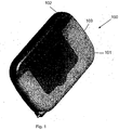
- FIG. 1 illustrates an embodiment of a fluid delivery device 100 having a dispensing unit 101, according to the present invention.
- the fluid delivery device includes a dispensing unit configured to be adherable to the skin of the patient, and a separate remote control unit (not shown).
- the dispensing unit can be referred to as a dispensing patch unit.
- the term dispensing unit is equally applicable to an adherable to the skin (i.e. patch unit) and non-adherable to the skin dispensing units.
- the dispensing unit 101 is configured to include a disposable part 103 and a reusable part 102. This configuration of the fluid delivery device 100 is disclosed in Israel Patent Application No. 171813 .
- One of the advantages of this configuration is that the relatively expensive components of the dispensing unit 101 are contained within the reusable part 102 and less expensive components are contained within the disposable part 103. By virtue of this provision the use of the device 100 is more economical for the patient.
- FIG. 2A illustrates the two parts of the dispensing unit 101.
- a reusable part 102 is configured to be operatively coupled to a disposable part 103.
- the dispensing unit 101 includes an occlusion sensor, discussed below.
- the occlusion sensor can be a pressure sensor, a capacitance sensor, an optical sensor, or other type of sensor.
- the occlusion sensor includes a reusable portion 204, and can be configured to include a disposable portion 205.
- the disposable portion 205 can be configured to be included in the reusable part 102 and/or disposable part 103 of the dispensing unit 101.
- the unit 101 including the occlusion sensor becomes operative.
- the unit 101 also includes a printed circuit board 214 ("PCB").
- the PCB 214 includes a processor and other electronic components. Once the unit 101 becomes operative, the sensor is activated and configured to detect an occlusion in the fluid delivery tube. Also, the PCB 214 is configured to begin collecting data, processing, and performing data analysis.
- FIG. 2B illustrates the reusable part 102 coupled to the disposable part 103.
- the disposable part 103 contains a reservoir 227.
- a delivery tube 217 connects an inlet portion 228 and an outlet portion 229.
- the inlet portion 228 is in flow communication with reservoir 227.
- the outlet portion 229 is connected to a subcutaneous cannula (not shown).
- the delivery tube 217 is placed between a stator plate 215 of the disposable part 103 and a peristaltic pump rotary wheel 216 within the reusable part 102.
- Rotary wheel 216 rotates rollers that squeeze the delivery tube 217 against the stator plate 215.
- the therapeutic fluid is periodically pumped from the reservoir 227 via the inlet portion 228 to the delivery tube 217 and then via outlet portion 229 to the cannula (not shown).
- the device 100 further includes an occlusion sensor 225, which is configured to be placed near the outlet portion 229.
- the sensor 225 is configured to detect occlusion occurring downstream in the outlet portion 229 and/or in the cannula.
- the dispensing unit 101 can include an alternative pumping mechanism, e.g., a syringe pump, piston pump, or any other pump suitable for these purposes.
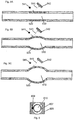
- FIGS. 3A-4C illustrate longitudinal and cross-sectional views of a delivery tube 310 configured with an optical device sensor for detecting an occlusion.
- the fluid delivery tube 310 includes a dedicated region 320.
- the dedicated region 320 is configured to be defined by sidewalls 322.
- the sidewalls 322 are configured to be manufactured from a more expendable elastic material than the rest of the tube.
- the optical device 300 further includes a light-collecting array 332 and a light-emitting source 331 (shown in FIGS. 4A-4C ).
- the array 332 and the source 331 are configured to be positioned on opposite sides of the fluid delivery tube 310.
- the source 331 is configured to emit light 301 toward the array 332.
- the fluid delivery tube 310 casts a shadow on the array 332 (illustrated by the dark-colored or shaded zones 334 in FIGS. 4A-4C ).
- the zones over which the delivery tube 310 do not cast a shadow are designated as light-colored zones 333 in FIGS. 4A-4C .
- it induces radial expansion of the dedicated region 320. This is illustrated in FIGS. 3B-3C and FIGS. 4B- 4C . Because of such expansion, the shadow cast by the expanded region 320 is greater than the shadow cast by the unexpanded region 320, thus, this causes the dark-colored zones 334 to expand and light-colored zones 333 to contract.
- the expansion of zones 334 and the contraction of zones 333 are configured to be detected by the light-collecting array 332.
- a processor (not shown) is configured to collect and interpret data as partial and/or full occlusion, based on such detection.
- the present invention is also configured to interpret reduction of tube's size as leakage of fluid from the tube. Further, periodic change in tube's diameter can be interpreted as a normal pulsating fluid delivery.
- the sensibility of the occlusion detection method above can be adjusted by changing the distance between the light-emitting source 331 and the light-collecting array 332.
- FIG. 5A illustrates yet another preferred embodiment of an optical detection device for detecting pressure variation in the fluid delivery tube 510.
- the optical device includes a light-collecting array 542 and a light-emitting source 541.
- the array 542 and the source 541 are configured to be positioned on the same side of a dedicated region 520.
- the light emitted by the light-emitting source 541 is configured to be reflected by the opposite side of the dedicated region 520 and then sensed by the light-collecting array 542.
- FIGS. 5B and 5C illustrate downstream occlusion detection in the fluid delivery tube 510.
- an upstream pressure elevation in the tube 510 is configured to induce a radial expansion of the dedicated region 520.
- a beam of light 543 emitted by the light-emitting source 541 is reflected at a particular angle. The angle of reflection is configured to vary in proportion to a curvature of the dedicated region 520.
- the beam 543 is consequently configured to be detected by the light collecting array 542.
- a processor collects light beam 543 reflection data and is configured to interpret it as occlusion or any other tube condition, such as leakage. In some embodiments, reduction of tube's size can be interpreted as leakage. Additionally, periodic change in tube's diameter can also be interpreted as a normal pulsating fluid delivery.
- FIG. 6 illustrates another aspect of the present disclosure, in which radial expansion is sensed by a pressure sensor 609.
- a housing 608 surrounds at least a portion of a fluid delivery tube 610.
- the tube 610 is configured to be coupled to the pressure sensor 609.
- the pressure sensor 609 is configured to be positioned in close proximity to a wall 607 of the tube 610.
- the pressure sensor 609 can be configured to be electrically coupled to at least one resistor that may be arranged in a Wheatstone bridge (not shown in FIG. 6 ).
- an upstream pressure in the fluid delivery tube 610 causes radial expansion of the tube wall 607.
- the radial expansion of the tube wall 607 is configured to cause deformation of the pressure sensor 609 (an exemplary pressure sensor can be a Metrodyne Microsystems's MPS-1060 sensor, or any other sensor). This deformation further alters sensor's 609 resistance.
- a processor (not shown in FIG. 6 ) configured to be coupled to the system can interpret such change as occlusion.
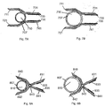
- FIGS. 7A-B illustrate another aspect of the present disclosure 's system for monitoring pressure changes in the delivery tube 710 and fluid delivery tube's wall 707 expansion.
- the system includes two levers 711, 721 configured to embrace at least a portion of tube's wall 707.
- the levers 711, 721 further include tail portions 731, 741, respectively.
- the tail portions 731, 741 are configured to include electrically conductive regions 733, 735, respectively.
- the electrically conductive regions 733, 735 are configured to be metallic plates.
- the conductive regions 733, 735 are configured to form a capacitor. The capacitance of which is configured to change in accordance with the distance between the regions 733 and 735.
- a processor configured to be coupled to the system is configured to interpret such change in capacitance. Based on the amount of the change, the processor can estimate the change in a diameter of the fluid delivery tube 710. The processor can further determine whether the change in the diameter is a result of a downstream occlusion in the fluid delivery tube 710, a leakage in the tube, or a normal pulsating delivery of a therapeutic fluid through the tube 710.
- FIGS. 8A-8B illustrate another aspect where a wall 807 of the fluid delivery tube 810 is configured to be embraced by levers 840, 842.
- the levers 840, 842 are configured to pivot around an axis 843.
- the levers 840, 842 are configured to have a scissors-like shape.
- other types of arrangement of levers 840, 842 are possible.
- the levers 840, 842 are configured to include tail portions 831, 841.
- the tail portions 831, 841 are configured to include conductive regions 833, 835.
- FIGS. 8A-8B illustrate another aspect where a wall 807 of the fluid delivery tube 810 is configured to be embraced by levers 840, 842.
- the levers 840, 842 are configured to pivot around an axis 843.
- the levers 840, 842 are configured to have a scissors-like shape.
- the levers 840, 842 are configured to include tail portions 831, 841.
- the conductive regions 833, 835 are configured to form a capacitor once current is passed through the regions 833, 835. Capacitance of this capacitor depends on the distance between the conductive regions 833, 835. As such, variation in the distance between regions 833, 835 causes variation of capacitance in the capacitor formed by the regions 833, 835.
- a processor (not shown in FIGS. 8A-8B ) can be configured to be coupled to the system 800 and can be further configured to interpret variation in the distance between the regions 833, 835 as variation of pressure in tube 810.
- the processor can be configured to interpret change of pressure in the fluid delivery tube 810 as either downstream occlusion, leakage in the tube, normal pulsating delivery of the fluid, or any other condition in the tube.
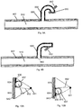
- FIGS. 9A-9B and 10A-10B illustrate longitudinal and cross sectional views of an exemplary fluid delivery tube 910.
- an L-shaped tubular protrusion 930 is configured to extend from the fluid delivery tube 910.
- the protrusion 930 further includes a first end 950 and a second end 960.
- First end 950 of the tubular protrusion 930 is configured to be closed (i.e., it is a blind end) and the second end 960 is configured to be open such that fluid communication is allowed between tube 910 and tubular protrusion 930.
- the tubular protrusion 930 can be configured to be a Bourdon gauge that can be further configured to change its configuration in response to pressure variation in fluid delivery tube 910. In some aspects, such variation of tubular protrusion's configuration can be detected by various methods, e.g., optical detection methods, force and pressure sensing methods.
- the fluid delivery tube 910 further includes a light-collecting array 942 (in some embodiments, the array can be a small CCD sensor) and a light-emitting source 941 (shown in FIGS. 10A-10B ).
- the array 942 and the source 941 are configured to be located on the opposite sides of the protrusion 930 and specifically on the opposite sides of the closed end 950, as illustrated in FIGS. 9A-9B .
- the protrusion 930 is configured to block the light 932 emanating from the source 941 to the ligh-collecting array 942.
- FIGS. 10A-10B are cross-sectional views of the fluid delivery tube 910 illustrated in FIGS. 9A-9B , respectively.
- the light collecting array 942 includes a shaded portion 934 and an illuminated portion 933.
- the shaded portion 934 represents a portion of the light collecting array 942 that is blocked by the protrusion 930 of the tube 910.
- the illuminated portion 933 represents a portion of the light collecting array 942 that is not currently blocked by the protrusion 930. Because of downstream occlusions (or any other conditions occurring in the tube), locations of the shaded portion 934 and the illuminated portion 933 on the light collecting array 942 may change, as shown in FIGS. 10A-10B .
- the location change is caused by the movement of the closed end 950.
- the movement of the closed end 950 is caused by rising pressure within the tube 910 (e.g., pressure rise caused by a Bourdon effect occlusion within the tube 910).
- FIG. 9A illustrates that there is substantially no pressure change within the tube 910 and, hence, no downstream occlusion has occurred in the tube 910. This is illustrated by the closed end 950 have a substantially curved shape, as illustrated in FIG. 9A.
- FIG. 9B (and corresponding FIG. 10B ) illustrates that there is increase and/or other change in pressure within the tube 910 that may be caused by a downstream occlusion or any other effect.
- Such change in pressure causes the closed end 950 to become substantially straight, as illustrated in FIG. 9B .
- its shadow (produced as a result of the light 933 emitted by the light source 941 towards light collecting array 942) shifts along the light collecting array 942, as illustrated in FIGS. 10A-10B .
- a processor (not shown in FIGS. 9A-10B ) can be configured to be coupled to the system 900 and interpret shifting of the shaded portions 934 as caused by a downstream occlusion, normal pulsating operation, leakage in the tube, or any other conditions.
- FIGS. 11A-11B are longitudinal views of another aspect of the tube 1110.
- the tube 1110 includes protrusion 1130.
- Protrusion 1130 includes a closed end 1150 and an open end 1160.
- the open end 1160 communicates with the main tube 1110.
- a light collecting array 1142 and a light-emitting source 1141 are located at the same side of the protrusion 1130 and, more specifically, on the same side of the closed end 1150.
- light beam 1132 emitted by the source 1141, is reflected off of a surface of the closed end 1150 of the protrusion 1130.
- the reflected light beam 1132 is collected by the light collecting array 1142.
- the closed end 1150 of the protrusion 1130 is configured to become straight ( FIG. 11B ) as opposed to substantially curved ( FIG. 11A ).
- Such change causes the angle arid the location of reflection formed by the light beam 1132 on the surface of the closed end 1150 to change.
- light beam 1132 emitted by the source 1141 hits the closed end 1150 at location A and is collected at location AA on the light collecting array 1142.
- the light beam 1132 hits the closed end 1150 at location B and is collected at location BB on the light collecting array 1142, as illustrated in FIG. 11B .
- a processor (not shown in FIGS.
- 11A-11B may be configured to be coupled to the system 1100 and interpret such change of collection location as downstream occlusion, normal pulsating delivery of fluid through the tube 1110, leakage in the tube 1110, or any other condition occurring in the system 1100 that causes change of location.
- FIG. 12 illustrates an exemplary dispensing unit 1200.
- the dispensing unit 1200 includes a reservoir 1227 that contains therapeutic fluid (e.g. insulin), a cannula 1245, a pump 1216, a delivery tube 1210, and an occlusion sensor 1205.
- the therapeutic fluid is configured to be delivered to the patient through the cannula 1245.
- the occlusion sensor 1205 can be a pressure sensor, a capacitance sensor, an optical sensor, or any other suitable sensor.
- the occlusion sensor 1205 is configured to detect an occlusion occurring in the tube 1210. As illustrated in FIG.
- such an occlusion 1240 can be a partial occlusion 1241, 1242 (where occlusions 1241 and 1242 differ by a degree of actual occlusion in the tube 1210; in the shown example, occlusion 1242 is greater than occlusion 1241) or a complete occlusion 1243.
- the tube 1210 can have one or more occlusions 1240 occurring at the same time.
- the therapeutic fluid can be delivered to the patient via a pulsating pumping mechanism. Waves generated by the pulsating mechanism in the fluid delivery tube 1210 can be depicted in pressure-time plots, as illustrated in FIGS. 14A-14C .
- y-axis of the plots corresponds to pressure exerted by the fluid in the fluid delivery tube and x-axis corresponds to time over which such pressure is exerted.
- a substantially non-occluded delivery of the fluid to the patient can be represented by curve A1 having equally spaced peaks (corresponding to pulses generated by the pulsating mechanism) on the pressure-time plot. This is illustrated in FIGS. 14A-14C .
- a threshold pressure setting may be set by the system that indicates above which pressure occlusion in the tube 1210 begins to occur. This is illustrated by a line 1401 in FIGS. 14A and 14B .
- threshold setting can be adjusted according to the desired setting of the system.
- the heights of all of the equally spaced peaks are configured to be below the threshold line 1401, as illustrated on the plot in FIG. 14A .
- Mild occlusion e.g., 40% of the tube is occluded
- Periods of mild occlusion are illustrated by a curve A2 in FIG. 14A .
- the peaks' heights of the curve A2 are slightly higher than the threshold line 1401.
- the system 1200 may choose to ignore detection of a mild occlusion by the sensor 1205.
- the sensor 1205 may be configured to various degrees of occlusions and the system 1200 can be configured to act as desired.
- FIG. 14b is another pressure-time plot illustrating a substantially non-occluded delivery of fluid (represented by curve A1) and delivery of fluid during periods of partial occlusions 1241, 1242 and full occlusions 1243 of the tube 1210 ( FIG. 13 ). Periods of partial and/or full occlusions of the delivery tube are illustrated by curve B. Because tube 1210 is experiencing an occlusion (whether partial or full), fluid delivery through tube 1210 becomes sporadic. As such, this causes fluid built-up, which corresponds to an increase in fluid pressure inside the tube 1210. Thus, the pressure-time curve representing fluid delivery through the tube loses its periodicity and symmetry, as illustrated in FIG. 14B .
- curve B crosses threshold line 1401 indicating an occlusion condition within tube 1210.
- the occlusion sensor 1205 is configured to detect these changing patterns of curve B and supply signals indicative of the occlusion in the tube 1210 to a processor (not shown in FIG. 12 ).
- the processor (and/or other electronic components) can be configured to process and interpret these signals and generate a warning and/or an alarm to the patient.
- the system 1200 can be configured to detect low-flow conditions within the delivery tube 1210.
- Low-flow conditions may occur when the pulsating flow through the tube 1210 is lower than is set by the system.
- the low-flow conditions may occur when there is a leak in the tube 1210.
- FIG. 14C is a pressure-time plot illustrating monitoring of flow conditions within the tube 1210.
- FIG. 14C illustrates curve A1 that corresponds to substantially non-occluded delivery of the fluid and curve C that corresponds to a low-flow condition. As can be seen from FIG. 14C , peaks in curve C have a significantly lower height than peaks in curve A1, which is indicative of a low flow condition in the tube 1210.
- FIG. 15 illustrates another exemplary fluid delivery system 1500. Similar to the fluid delivery system shown in FIG. 12 , the fluid delivery system 1500 includes a reservoir 1527, a pump 1516, a fluid delivery tube 1510 and an occlusion sensor 1505. Additionally, the fluid delivery system 1500 also includes a control valve 1555. The control valve 1555 has a closed and an open state. In the closed state, the valve 1555 does not allow any fluid to be delivered through the tube 1510. In the open state, the valve 1555 allows fluid delivery through the tube 1510. In some embodiments of the present invention, a processor (not shown in FIG. 15 ) can be configured to be coupled to the valve 1555 and to control opening and closing of the valve 1555 based on operation of the pump 1516.
- a processor (not shown in FIG. 15 ) can be configured to be coupled to the valve 1555 and to control opening and closing of the valve 1555 based on operation of the pump 1516.
- FIG. 16A is a pressure-time plot illustrating operation of the pump 1516 shown in FIG. 15 .
- the valve 1555 operation can be configured to be synchronized with a normal operation of the pump 1516. This is illustrated by the curve A in FIG. 16A .
- the "normal" operation of the pump 1516 is characterized by a substantially non-occluded delivery of the fluid through the tube 1510.
- curve A includes periods of pressure alteration when pressure inside the tube begins to rise during pumping operating of the pump 1516.
- the valve 1555 remains closed. This is illustrated by segments 1625 (a, b, c).
- FIG. 16B is a pressure-time plot illustrating operation of the pump 1516 during total or partial occlusion occurring within the tube 1510.
- FIG. 16B includes a curve B, representing operation of the pump 1516 during total occlusion ( FIG. 13 ), and a curve C representing operation of the pump 1516 during partial occlusion ( FIG. 13 ). Similar to the discussion of FIGS. 14A-14C , curves B and C do not have the same periodicity or substantially the same amplitude, as curve A shown in FIG. 16A . The severity of change in periodicity and amplitude is dependent on the severity of occlusion occurring within the tube 1510. As the occlusion in the tube 1510 increases, the periodicity of the curve decreases and the amplitude increases (as shown by curve B, representing total occlusion).
- FIG. 16C is a pressure-time plot illustrating operation of the pump 1516 when air is present in the tube 1510 and a very mild occlusion occurs.
- FIG. 16C includes a curve E, representing operation of the pump 1516 when a large amount of air is present in the tube 1510, and a curve D, representing operation of the pump 1516 when a small amount of air is present in the tube 1510.
- the pressure inside the tube decreases, which is illustrated by the decreasing amplitude.
- the amplitude is greater (as illustrated by curve E).
- valve 1555 can be configured to provide high sensitivity required for occlusion detection sensors even when there is a fluid leak or air is present in the tube 1510.
- the valve 1555 can be configured to enhance signals corresponding to variation in pressure within the tube 1510. This improves sensitivity of occlusion detection and allows detection of variety of flow conditions, including partial or full occlusion or lack of fluid in the reservoir/leakage.
- the fluid delivery device discussed above with regard to FIGS. 1-16C is configured to be attached to the patient.
- the device can be configured to be a patch unit adherable to the skin of the patient.
- the fluid delivery device is configured to pump therapeutic fluid to the patient using a dispensing unit having a pumping mechanism.
- the dispensing unit is controlled by a remote control unit.
- the dispensing unit is configured to communicate with the remote control unit.
- the dispensing unit includes a delivery tube having an inlet portion and an outlet portion, where the inlet portion is configured to be coupled to a reservoir containing therapeutic fluid, as discussed above with regard to FIGS. 1-16C .
- the dispensing unit also includes a peristaltic pump having a stator plate and rotary wheel with rollers, wherein the stator plate and the rollers are configured to squeeze the fluid delivery tube.
- the peristaltic pump can be configured to pump fluid from the reservoir via the inlet portion of the tube to the outlet portion upon squeezing the fluid delivery tube.
- the dispensing unit also includes an occlusion sensor that can be configured to be located near the outlet portion of the fluid delivery tube, as discussed above with regard to FIGS. 1-16C . The sensor can be configured to detect occlusion within the fluid delivery tube.
Landscapes
- Health & Medical Sciences (AREA)
- Vascular Medicine (AREA)
- Engineering & Computer Science (AREA)
- Anesthesiology (AREA)
- Biomedical Technology (AREA)
- Heart & Thoracic Surgery (AREA)
- Hematology (AREA)
- Life Sciences & Earth Sciences (AREA)
- Animal Behavior & Ethology (AREA)
- General Health & Medical Sciences (AREA)
- Public Health (AREA)
- Veterinary Medicine (AREA)
- Infusion, Injection, And Reservoir Apparatuses (AREA)
Claims (15)
- Fluidabgabevorrichtung (100) zum Abgeben von therapeutischem Fluid an einen Patienten, umfassend eine Abgabeeinheit (101), umfassend:einen Fluidabgabeschlauch (310), enthaltend einen Okklusionsdetektionsabschnitt (320); einen Behälter (227), der mit dem Fluidabgabeschlauch (310) gekoppelt und konfiguriert ist, um therapeutisches Fluid über den Fluidabgabeschlauch (310) an den Patienten abzugeben;einen Okklusionsdetektionssensor (225), der konfiguriert ist, um an den Fluidabgabeschlauch (310) gekoppelt zu werden, wobei der Okklusionsdetektionssensor (225) ferner konfiguriert ist, um eine Änderung einer Form des Okklusionsdetektionsabschnitts (320) zu detektieren, wenn im Fluidabgabeschlauch (310) eine Fluiddruckänderung auftritt; und eine PCB, umfassend einen Prozessor und andere elektronische Komponenten, die Daten vom Okklusionsdetektionssensor (225) sammeln und konfiguriert sind, um eine Okklusion im Fluidabgabeschlauch (310) zu detektieren und die normale Abgabe des therapeutischen Fluids an den Patienten basierend auf einem vorbestimmten Druckwert des Fluids, entsprechend der normalen Fluidabgabe, zu detektieren; dadurch gekennzeichnet, dass:
die Abgabeeinheit enthält: einen wiederverwendbaren Teil (102), enthaltend Komponenten eines Fluidmesssystems, elektronische Schaltkreise und andere Komponenten; und einen wegwerfbaren Teil (103), enthaltend den Okklusionsdetektionsabschnitt (320) des Fluidabgabeschlauchs (310), die Abgabeeinheit (101) und den Okklusionsdetektorsensor (225); wobei die Abgabeeinheit (101) und der Okklusionsdetektionssensor (225) konfiguriert sind, um bei Zusammenkoppeln des wiederverwendbaren Teils (102) und des wegwerfbaren Teils (103) operativ zu werden. - Fluidabgabevorrichtung (100) nach Anspruch 1, wobei die Abgabeeinheit (101) konfiguriert ist, um therapeutisches Fluid aus dem Behälter (227) zu pumpen, wobei die Abgabeeinheit (101) enthält:eine peristaltische Pumpe mit einer Statorplatte (215) und einer Drehscheibe (216) mit Walzen, wobei die Statorplatte und die Walzen konfiguriert sind, den Fluidabgabeschlauch zwischen die Statorplatte und die Walzen zu pressen;wobei die peristaltische Pumpe konfiguriert ist, um beim Pressen des Fluidabgabeschlauchs Fluid aus dem Behälter (227) zu pumpen.
- Fluidabgabevorrichtung (100) nach Anspruch 1, wobei der Okklusionsdetektionsabschnitt (320) konfiguriert ist, um sich zu erweitern, wenn der Fluiddruck im Fluidabgabeschlauch (310) zunimmt.
- Fluidabgabevorrichtung (100) nach Anspruch 1, wobei der Okklusionsdetektionsabschnitt (320) ein Vorsprung ist, der sich vom Fluidabgabeschlauch (310) erstreckt;
und wobei der Vorsprung konfiguriert ist, um seine Ausrichtung bezüglich des Fluidabgabeschlauchs zu ändern, wenn der Fluiddruck im Fluidabgabeschlauch zunimmt. - Fluidabgabevorrichtung (100) nach Anspruch 1, wobei der Okklusionsdetektionssensor eine Lichtausstrahlungsquelle und eine Lichtsammelanordnung umfasst;
wobei die Lichtausstrahlungsquelle konfiguriert ist, um Licht auszustrahlen, und die Lichtsammelanordnung konfiguriert ist, um das Licht zu sammeln. - Fluidabgabevorrichtung (100) nach Anspruch 5, wobei die Lichtausstrahlungsquelle konfiguriert ist, um Licht zum Okklusionsdetektionsabschnitt auszustrahlen und der Okklusionsdetektionsabschnitt konfiguriert ist, um das Licht in einem Reflexionswinkel zur Lichtsammelanordnung zu reflektieren.
- Fluidabgabevorrichtung (100) nach Anspruch 5, wobei die Lichtausstrahlungsquelle und die Lichtsammelanordnung konfiguriert sind, um sich auf derselben Seite des Okklusionsdetektionsabschnitts zu befinden.
- Fluidabgabevorrichtung (100) nach Anspruch 5, wobei die Lichtausstrahlungsquelle und die Lichtsammelanordnung konfiguriert sind, um sich auf gegenüberliegenden Seiten des Okklusionsdetektionsabschnitts zu befinden.
- Fluidabgabevorrichtung (100) nach Anspruch 1, wobei der Okklusionsdetektionssensor bewegliche Kapazitätsplatten umfasst;
wobei der Okklusionsdetektionsabschnitt konfiguriert ist, um bei Änderung des Fluiddrucks im Fluidabgabeschlauch einen Abstand zwischen den beweglichen Kapazitätsplatten zu ändern. - Fluidabgabevorrichtung (100) nach Anspruch 1, wobei der Okklusionsdetektionssensor konfiguriert ist, um einen Zustand im Okklusionsdetektionsabschnitt zu detektieren, ausgewählt aus einer Gruppe, bestehend aus: keine Okklusion, teilweise Okklusion und totale Okklusion.
- Fluidabgabevorrichtung (100) nach Anspruch 10, ferner umfassend eine Alarmvorrichtung, die konfiguriert ist, um den Patienten zu alarmieren, wenn der Okklusionsdetektionssensor eine mindestens teilweise Okklusion im Okklusionsdetektionsabschnitt detektiert.
- Fluidabgabevorrichtung (100) nach Anspruch 1, wobei der Okklusionsdetektionssensor konfiguriert ist, um ein Auslaufen von therapeutischem Fluid aus dem Fluidabgabeschlauch zu detektieren, wenn ein Druck des Fluids unter einen Schwellwertdruckwert abfällt.
- Fluidabgabevorrichtung (100) nach Anspruch 1, umfassend ein Steuerventil, wobei das Steuerventil konfiguriert ist, um die Abgabe des therapeutischen Fluids im Fluidabgabeschlauch zu steuern, wobei das Steuerventil so konfiguriert ist, dass, wenn es geschlossen ist, der Druck des therapeutischen Fluids im Fluidabgabeschlauch steigt, und wenn das Steuerventil offen ist, der Druck des therapeutischen Fluids im Fluidabgabeschlauch sinkt.
- Fluidabgabevorrichtung (100) nach Anspruch 13, wobei während des Normalbetriebs der Fluidabgabevorrichtung das Steigen und Sinken des Drucks im Fluidabgabeschlauch periodisch sind.
- Fluidabgabevorrichtung (100) nach Anspruch 1, wobei der Okklusionsdetektionssensor (225) einen wiederverwendbaren Abschnitt (204) und einen wegwerfbaren Abschnitt (205) enthält, wobei der wegwerfbare Abschnitt (205) konfiguriert ist, um im wiederverwendbaren Teil (102) und/oder im wegwerfbaren Teil der Abgabeeinheit (101) enthalten zu sein.
Applications Claiming Priority (2)
| Application Number | Priority Date | Filing Date | Title |
|---|---|---|---|
| US81254906P | 2006-06-08 | 2006-06-08 | |
| PCT/IL2007/000684 WO2007141786A1 (en) | 2006-06-08 | 2007-06-06 | System for detecting an occlusion in a tube |
Publications (2)
| Publication Number | Publication Date |
|---|---|
| EP2026862A1 EP2026862A1 (de) | 2009-02-25 |
| EP2026862B1 true EP2026862B1 (de) | 2019-08-14 |
Family
ID=38358040
Family Applications (1)
| Application Number | Title | Priority Date | Filing Date |
|---|---|---|---|
| EP07736424.8A Active EP2026862B1 (de) | 2006-06-08 | 2007-06-06 | System zum nachweis einer okklusion in einem schlauch |
Country Status (5)
| Country | Link |
|---|---|
| US (2) | US7875004B2 (de) |
| EP (1) | EP2026862B1 (de) |
| DK (1) | DK2026862T3 (de) |
| ES (1) | ES2751017T3 (de) |
| WO (1) | WO2007141786A1 (de) |
Families Citing this family (91)
| Publication number | Priority date | Publication date | Assignee | Title |
|---|---|---|---|---|
| EP2162168B1 (de) | 2005-09-26 | 2018-11-07 | Bigfoot Biomedical, Inc. | Modulare infusionspumpe mit zwei verschiedenen energiequellen |
| US8105279B2 (en) | 2005-09-26 | 2012-01-31 | M2 Group Holdings, Inc. | Dispensing fluid from an infusion pump system |
| US8167832B2 (en) * | 2006-12-09 | 2012-05-01 | The Alfred E. Mann Foundation For Scientific Research | Ambulatory infusion devices and methods including occlusion monitoring |
| CA2677343C (en) | 2007-02-05 | 2016-06-21 | Boston Scientific Limited | Thrombectomy apparatus and method |
| US7892199B2 (en) * | 2007-05-21 | 2011-02-22 | Asante Solutions, Inc. | Occlusion sensing for an infusion pump |
| US7981102B2 (en) | 2007-05-21 | 2011-07-19 | Asante Solutions, Inc. | Removable controller for an infusion pump |
| US7833196B2 (en) | 2007-05-21 | 2010-11-16 | Asante Solutions, Inc. | Illumination instrument for an infusion pump |
| US7751907B2 (en) | 2007-05-24 | 2010-07-06 | Smiths Medical Asd, Inc. | Expert system for insulin pump therapy |
| US8221345B2 (en) | 2007-05-30 | 2012-07-17 | Smiths Medical Asd, Inc. | Insulin pump based expert system |
| EP2185218B1 (de) | 2007-08-01 | 2013-06-26 | Medingo Ltd. | Ablösbare tragbare infusionsvorrichtung |
| US7867192B2 (en) * | 2008-02-29 | 2011-01-11 | The Alfred E. Mann Foundation For Scientific Research | Ambulatory infusion devices and methods with blockage detection |
| WO2009113075A1 (en) * | 2008-03-12 | 2009-09-17 | Medingo Ltd. | Devices and methods for improving accuracy of fluid delivery |
| AU2009235064A1 (en) | 2008-04-09 | 2009-10-15 | F.Hoffmann-La Roche Ag | Modular skin-adherable system for medical fluid delivery |
| US8128597B2 (en) | 2008-06-26 | 2012-03-06 | Calibra Medical, Inc. | Disposable infusion device with cannula port cover |
| US7959598B2 (en) | 2008-08-20 | 2011-06-14 | Asante Solutions, Inc. | Infusion pump systems and methods |
| US9510854B2 (en) | 2008-10-13 | 2016-12-06 | Boston Scientific Scimed, Inc. | Thrombectomy catheter with control box having pressure/vacuum valve for synchronous aspiration and fluid irrigation |
| CA2993719C (en) | 2009-01-12 | 2022-04-19 | Becton, Dickinson And Company | Infusion set and/or patch pump having at least one of an in-dwelling rigid catheter with flexible features and/or a flexible catheter attachment |
| US9375529B2 (en) | 2009-09-02 | 2016-06-28 | Becton, Dickinson And Company | Extended use medical device |
| US20100217233A1 (en) * | 2009-02-20 | 2010-08-26 | Ranft Elizabeth A | Method and device to anesthetize an area |
| US20100280486A1 (en) * | 2009-04-29 | 2010-11-04 | Hospira, Inc. | System and method for delivering and monitoring medication |
| MX2012000700A (es) * | 2009-07-13 | 2012-03-16 | Nestec Sa | Cartuchos y metodos de uso de los mismos. |
| CN102548597B (zh) | 2009-08-26 | 2017-03-22 | 雀巢产品技术援助有限公司 | 红外线反射闭塞传感器 |
| US8882701B2 (en) | 2009-12-04 | 2014-11-11 | Smiths Medical Asd, Inc. | Advanced step therapy delivery for an ambulatory infusion pump and system |
| US9677555B2 (en) | 2011-12-21 | 2017-06-13 | Deka Products Limited Partnership | System, method, and apparatus for infusing fluid |
| USD669165S1 (en) | 2010-05-27 | 2012-10-16 | Asante Solutions, Inc. | Infusion pump |
| US9737657B2 (en) | 2010-06-03 | 2017-08-22 | Medtronic, Inc. | Implantable medical pump with pressure sensor |
| US8397578B2 (en) | 2010-06-03 | 2013-03-19 | Medtronic, Inc. | Capacitive pressure sensor assembly |
| US9216249B2 (en) | 2010-09-24 | 2015-12-22 | Perqflo, Llc | Infusion pumps |
| US9308320B2 (en) | 2010-09-24 | 2016-04-12 | Perqflo, Llc | Infusion pumps |
| US9498573B2 (en) | 2010-09-24 | 2016-11-22 | Perqflo, Llc | Infusion pumps |
| US8915879B2 (en) | 2010-09-24 | 2014-12-23 | Perqflo, Llc | Infusion pumps |
| DK2635323T3 (da) | 2010-11-01 | 2020-03-23 | Hoffmann La Roche | Fluiddoseringsanordning med en strømningsdetektor |
| US8905972B2 (en) | 2010-11-20 | 2014-12-09 | Perqflo, Llc | Infusion pumps |
| US8814831B2 (en) | 2010-11-30 | 2014-08-26 | Becton, Dickinson And Company | Ballistic microneedle infusion device |
| US9950109B2 (en) | 2010-11-30 | 2018-04-24 | Becton, Dickinson And Company | Slide-activated angled inserter and cantilevered ballistic insertion for intradermal drug infusion |
| US8795230B2 (en) | 2010-11-30 | 2014-08-05 | Becton, Dickinson And Company | Adjustable height needle infusion device |
| US8808230B2 (en) | 2011-09-07 | 2014-08-19 | Asante Solutions, Inc. | Occlusion detection for an infusion pump system |
| US11295846B2 (en) | 2011-12-21 | 2022-04-05 | Deka Products Limited Partnership | System, method, and apparatus for infusing fluid |
| US9675756B2 (en) | 2011-12-21 | 2017-06-13 | Deka Products Limited Partnership | Apparatus for infusing fluid |
| AU2013234034B2 (en) | 2012-03-12 | 2017-03-30 | Smith & Nephew Plc | Reduced pressure apparatus and methods |
| JP2015514526A (ja) | 2012-04-24 | 2015-05-21 | ノボ・ノルデイスク・エー/エス | 投与終了条件検出のための薬剤送達装置及び方法 |
| US8454562B1 (en) | 2012-07-20 | 2013-06-04 | Asante Solutions, Inc. | Infusion pump system and method |
| EP2882362B1 (de) | 2012-08-09 | 2024-01-03 | Fractyl Health, Inc. | Ablationssysteme, vorrichtungen und verfahren zur gewebebehandlung |
| CN104363938B (zh) | 2012-12-31 | 2017-04-26 | 甘布罗伦迪亚股份公司 | 流体输送中的堵塞检测 |
| US9457141B2 (en) | 2013-06-03 | 2016-10-04 | Bigfoot Biomedical, Inc. | Infusion pump system and method |
| US9561324B2 (en) | 2013-07-19 | 2017-02-07 | Bigfoot Biomedical, Inc. | Infusion pump system and method |
| KR102235689B1 (ko) * | 2013-07-30 | 2021-04-02 | 삼성전자주식회사 | 유체 막힘 센싱 장치 및 유체 막힘 센싱 방법. |
| US9565718B2 (en) | 2013-09-10 | 2017-02-07 | Tandem Diabetes Care, Inc. | System and method for detecting and transmitting medical device alarm with a smartphone application |
| EP3071286B1 (de) | 2013-11-22 | 2024-01-03 | Fractyl Health, Inc. | Systeme zur erzeugung einer therapeutischen einschränkung im magen-darm-trakt |
| US10569015B2 (en) | 2013-12-02 | 2020-02-25 | Bigfoot Biomedical, Inc. | Infusion pump system and method |
| US10959774B2 (en) | 2014-03-24 | 2021-03-30 | Fractyl Laboratories, Inc. | Injectate delivery devices, systems and methods |
| US9248221B2 (en) | 2014-04-08 | 2016-02-02 | Incuvate, Llc | Aspiration monitoring system and method |
| US9433427B2 (en) | 2014-04-08 | 2016-09-06 | Incuvate, Llc | Systems and methods for management of thrombosis |
| US9883877B2 (en) | 2014-05-19 | 2018-02-06 | Walk Vascular, Llc | Systems and methods for removal of blood and thrombotic material |
| US9757535B2 (en) | 2014-07-16 | 2017-09-12 | Fractyl Laboratories, Inc. | Systems, devices and methods for performing medical procedures in the intestine |
| US11185367B2 (en) | 2014-07-16 | 2021-11-30 | Fractyl Health, Inc. | Methods and systems for treating diabetes and related diseases and disorders |
| US10137246B2 (en) | 2014-08-06 | 2018-11-27 | Bigfoot Biomedical, Inc. | Infusion pump assembly and method |
| US10227971B2 (en) | 2014-08-12 | 2019-03-12 | Kpr U.S., Llc | Downstream flow detection system for flow control apparatus |
| AU2015308144B2 (en) * | 2014-08-26 | 2020-07-02 | Debiotech S.A. | Detection of an infusion anomaly |
| AU2015318119B2 (en) | 2014-09-18 | 2019-07-11 | Deka Products Limited Partnership | Apparatus and method for infusing fluid through a tube by appropriately heating the tube |
| US10159786B2 (en) | 2014-09-30 | 2018-12-25 | Perqflo, Llc | Hybrid ambulatory infusion pumps |
| WO2016133789A2 (en) | 2015-02-18 | 2016-08-25 | Perqflo, Llc | Ambulatory infusion pump and reservoir assemblies for use with same |
| WO2016168162A1 (en) | 2015-04-15 | 2016-10-20 | Gambro Lundia Ab | Treatment system with infusion apparatus pressure priming |
| US9878097B2 (en) | 2015-04-29 | 2018-01-30 | Bigfoot Biomedical, Inc. | Operating an infusion pump system |
| US10702292B2 (en) | 2015-08-28 | 2020-07-07 | Incuvate, Llc | Aspiration monitoring system and method |
| US10561440B2 (en) | 2015-09-03 | 2020-02-18 | Vesatek, Llc | Systems and methods for manipulating medical devices |
| US20170100142A1 (en) | 2015-10-09 | 2017-04-13 | Incuvate, Llc | Systems and methods for management of thrombosis |
| US10226263B2 (en) | 2015-12-23 | 2019-03-12 | Incuvate, Llc | Aspiration monitoring system and method |
| US10569016B2 (en) | 2015-12-29 | 2020-02-25 | Tandem Diabetes Care, Inc. | System and method for switching between closed loop and open loop control of an ambulatory infusion pump |
| EP3374900A1 (de) | 2016-01-05 | 2018-09-19 | Bigfoot Biomedical, Inc. | Betrieb von multimodalen arzneimittelabgabesystemen |
| GB201600235D0 (en) * | 2016-01-06 | 2016-02-17 | Vicentra B V | Infusion pump system and associated methods |
| EP3405232B1 (de) | 2016-01-20 | 2023-10-18 | Medtronic MiniMed, Inc. | Ambulante infusionsvorrichtungen und entsprechende verfahren |
| AU2017218443A1 (en) | 2016-02-12 | 2018-08-30 | Medtronic Minimed, Inc. | Ambulatory infusion pumps and assemblies for use with same |
| USD809134S1 (en) | 2016-03-10 | 2018-01-30 | Bigfoot Biomedical, Inc. | Infusion pump assembly |
| US10492805B2 (en) | 2016-04-06 | 2019-12-03 | Walk Vascular, Llc | Systems and methods for thrombolysis and delivery of an agent |
| US10172993B2 (en) | 2016-04-14 | 2019-01-08 | Fresenius Medical Care Holdings, Inc. | Wave-based patient line blockage detection |
| EP3519011A4 (de) | 2016-09-27 | 2020-05-20 | Bigfoot Biomedical, Inc. | Medizininjektions- und krankheitsmanagementsysteme, -vorrichtungen und -verfahren |
| US10865787B2 (en) * | 2016-12-06 | 2020-12-15 | Pentair Flow Technologies, Llc | Connected pump system controller and method of use |
| USD836769S1 (en) | 2016-12-12 | 2018-12-25 | Bigfoot Biomedical, Inc. | Insulin delivery controller |
| EP3500161A4 (de) | 2016-12-12 | 2020-01-08 | Bigfoot Biomedical, Inc. | Alarme und warnungen für medikamentenabgabevorrichtungen und zugehörige systeme und verfahren |
| USD839294S1 (en) | 2017-06-16 | 2019-01-29 | Bigfoot Biomedical, Inc. | Display screen with graphical user interface for closed-loop medication delivery |
| US11389088B2 (en) | 2017-07-13 | 2022-07-19 | Bigfoot Biomedical, Inc. | Multi-scale display of blood glucose information |
| WO2019155453A1 (en) | 2018-02-11 | 2019-08-15 | Avoset Health Ltd. | Flex-stroke infusion pump |
| DE102018106226A1 (de) * | 2018-03-16 | 2019-09-19 | Fresenius Medical Care Deutschland Gmbh | Vorrichtung und Verfahren zur Überwachung des Zugangs zu einem Patienten |
| US11678905B2 (en) | 2018-07-19 | 2023-06-20 | Walk Vascular, Llc | Systems and methods for removal of blood and thrombotic material |
| MX2021001825A (es) | 2018-08-16 | 2021-07-15 | Deka Products Lp | Bomba medica. |
| EP3705148B1 (de) | 2019-03-04 | 2024-06-19 | Eitan Medical Ltd. | Druckmessung in einem kreislauf |
| US11890451B2 (en) | 2019-03-05 | 2024-02-06 | Eitan Medical Ltd. | Anti-free-flow valve |
| CN113905775A (zh) * | 2019-04-16 | 2022-01-07 | 英福森创新有限责任公司 | 传感器阵列 |
| CN112107761B (zh) * | 2019-06-21 | 2022-10-28 | 深圳迈瑞科技有限公司 | 一种输液泵、输液泵工作方法、医疗设备及存储介质 |
| CN115135358B (zh) * | 2020-02-27 | 2024-07-02 | 美国西门子医学诊断股份有限公司 | 使用机器学习的自动传感器追踪验证 |
Family Cites Families (24)
| Publication number | Priority date | Publication date | Assignee | Title |
|---|---|---|---|---|
| JPS5631758A (en) | 1979-08-24 | 1981-03-31 | Sharp Kk | Detector for clogging condition of flexible tube |
| JPS56113083A (en) * | 1980-02-12 | 1981-09-05 | Terumo Corp | Choke detection method and device for peristaltic liquid pump |
| US4690673A (en) * | 1985-11-26 | 1987-09-01 | Imed Corporation | Dual mode I.V. infusion device with distal sensor |
| US5575310A (en) * | 1986-03-04 | 1996-11-19 | Deka Products Limited Partnership | Flow control system with volume-measuring system using a resonatable mass |
| US4762518A (en) * | 1986-08-01 | 1988-08-09 | Pancretec, Inc. | Blockage hazard alarm in an intravenous system |
| US4838860A (en) * | 1987-06-26 | 1989-06-13 | Pump Controller Corporation | Infusion pump |
| US5074756A (en) * | 1988-05-17 | 1991-12-24 | Patient Solutions, Inc. | Infusion device with disposable elements |
| US5531300A (en) * | 1994-11-15 | 1996-07-02 | Tsai; James | Retractable handle assembly for a suitcase |
| US5514102A (en) * | 1995-05-05 | 1996-05-07 | Zevex Incorporated | Pressure monitoring enteral feeding system and method |
| US5853386A (en) | 1996-07-25 | 1998-12-29 | Alaris Medical Systems, Inc. | Infusion device with disposable elements |
| US6368080B1 (en) * | 1997-08-04 | 2002-04-09 | Anatole J. Sipin | Continuous fluid injection pump |
| US6149394A (en) | 1999-02-26 | 2000-11-21 | Allen; Alton K. | Occlusion detection means for a persistaltic pump |
| US6458102B1 (en) * | 1999-05-28 | 2002-10-01 | Medtronic Minimed, Inc. | External gas powered programmable infusion device |
| US6423035B1 (en) | 1999-06-18 | 2002-07-23 | Animas Corporation | Infusion pump with a sealed drive mechanism and improved method of occlusion detection |
| WO2002068015A2 (en) * | 2001-02-22 | 2002-09-06 | Insulet Corporation | Modular infusion device and method |
| US6523414B1 (en) | 2001-04-16 | 2003-02-25 | Zevex, Inc. | Optical pressure monitoring system |
| ATE402724T1 (de) * | 2002-02-18 | 2008-08-15 | Danfoss As | Vorrichtung zur verabreichung eines medikaments in flüssiger form |
| US6830558B2 (en) * | 2002-03-01 | 2004-12-14 | Insulet Corporation | Flow condition sensor assembly for patient infusion device |
| US8021334B2 (en) * | 2004-05-30 | 2011-09-20 | Nilimedix Ltd. | Drug delivery device and method |
| WO2005007223A2 (en) * | 2003-07-16 | 2005-01-27 | Sasha John | Programmable medical drug delivery systems and methods for delivery of multiple fluids and concentrations |
| KR20060099520A (ko) * | 2003-10-21 | 2006-09-19 | 노보 노르디스크 에이/에스 | 의료용 피부 장착 장치 |
| WO2006120253A2 (en) * | 2005-05-13 | 2006-11-16 | Novo Nordisk A/S | Medical device adapted to detect disengagement of a transcutaneous device |
| US7935104B2 (en) | 2005-11-07 | 2011-05-03 | Medingo, Ltd. | Systems and methods for sustained medical infusion and devices related thereto |
| EP1818664B1 (de) * | 2006-02-13 | 2013-05-01 | F.Hoffmann-La Roche Ag | Vorrichtung zur Erkennung einer Druckänderung im Flüssigkeitspfad einer Mikrodosiervorrichtung |
-
2007
- 2007-06-06 EP EP07736424.8A patent/EP2026862B1/de active Active
- 2007-06-06 ES ES07736424T patent/ES2751017T3/es active Active
- 2007-06-06 US US11/810,854 patent/US7875004B2/en active Active
- 2007-06-06 WO PCT/IL2007/000684 patent/WO2007141786A1/en active Application Filing
- 2007-06-06 DK DK07736424.8T patent/DK2026862T3/da active
-
2011
- 2011-01-10 US US12/987,515 patent/US8486005B2/en active Active
Non-Patent Citations (1)
| Title |
|---|
| None * |
Also Published As
| Publication number | Publication date |
|---|---|
| WO2007141786B1 (en) | 2008-01-31 |
| DK2026862T3 (da) | 2019-10-21 |
| EP2026862A1 (de) | 2009-02-25 |
| US20080021395A1 (en) | 2008-01-24 |
| ES2751017T3 (es) | 2020-03-30 |
| WO2007141786A1 (en) | 2007-12-13 |
| US20110172594A1 (en) | 2011-07-14 |
| US8486005B2 (en) | 2013-07-16 |
| US7875004B2 (en) | 2011-01-25 |
Similar Documents
| Publication | Publication Date | Title |
|---|---|---|
| EP2026862B1 (de) | System zum nachweis einer okklusion in einem schlauch | |
| AU609804B2 (en) | Pressure sensor assembly for disposable pump cassette | |
| US6572604B1 (en) | Occlusion detection method and system for ambulatory drug infusion pump | |
| KR101616736B1 (ko) | 압력 센서 및 사용 방법 | |
| US5695473A (en) | Occlusion detection system for an infusion pump | |
| US9993594B2 (en) | Occlusion detection techniques for a fluid infusion device having a rotary pump mechanism and rotor position sensors | |
| US9879668B2 (en) | Occlusion detection techniques for a fluid infusion device having a rotary pump mechanism and an optical sensor | |
| JP2006514856A (ja) | 動作状態を判断する単一の力センサを有する医用カセットポンプ | |
| WO2012126744A1 (en) | Infusion system and method of integrity testing and leak detection | |
| WO2016209554A1 (en) | Occlusion detection techniques for a fluid infusion device having a rotary pump mechanism | |
| US9987425B2 (en) | Occlusion detection techniques for a fluid infusion device having a rotary pump mechanism and sensor contact elements | |
| US20160367754A1 (en) | Occlusion detection techniques for a fluid infusion device having a rotary pump mechanism and multiple sensor contact elements | |
| IL195396A (en) | System for detecting an occlusion in a tube | |
| US20220203027A1 (en) | A Sensor Array | |
| CN114618051A (zh) | 液体输送装置、输液管路的阻塞检测方法、装置及电路 | |
| WO2015095590A1 (en) | System and method of control of a reciprocating electrokinetic pump |
Legal Events
| Date | Code | Title | Description |
|---|---|---|---|
| PUAI | Public reference made under article 153(3) epc to a published international application that has entered the european phase |
Free format text: ORIGINAL CODE: 0009012 |
|
| 17P | Request for examination filed |
Effective date: 20081224 |
|
| AK | Designated contracting states |
Kind code of ref document: A1 Designated state(s): AT BE BG CH CY CZ DE DK EE ES FI FR GB GR HU IE IS IT LI LT LU LV MC MT NL PL PT RO SE SI SK TR |
|
| AX | Request for extension of the european patent |
Extension state: AL BA HR MK RS |
|
| RIN1 | Information on inventor provided before grant (corrected) |
Inventor name: SENESH, GIL Inventor name: IDDAN, GAVRIEL J. Inventor name: YODFAT, OFER |
|
| DAX | Request for extension of the european patent (deleted) | ||
| RAP1 | Party data changed (applicant data changed or rights of an application transferred) |
Owner name: ROCHE DIAGNOSTICS GMBH Owner name: F.HOFFMANN-LA ROCHE AG |
|
| RAP1 | Party data changed (applicant data changed or rights of an application transferred) |
Owner name: F.HOFFMANN-LA ROCHE AG Owner name: ROCHE DIABETES CARE GMBH |
|
| STAA | Information on the status of an ep patent application or granted ep patent |
Free format text: STATUS: EXAMINATION IS IN PROGRESS |
|
| 17Q | First examination report despatched |
Effective date: 20170313 |
|
| GRAP | Despatch of communication of intention to grant a patent |
Free format text: ORIGINAL CODE: EPIDOSNIGR1 |
|
| STAA | Information on the status of an ep patent application or granted ep patent |
Free format text: STATUS: GRANT OF PATENT IS INTENDED |
|
| INTG | Intention to grant announced |
Effective date: 20190502 |
|
| GRAS | Grant fee paid |
Free format text: ORIGINAL CODE: EPIDOSNIGR3 |
|
| GRAA | (expected) grant |
Free format text: ORIGINAL CODE: 0009210 |
|
| STAA | Information on the status of an ep patent application or granted ep patent |
Free format text: STATUS: THE PATENT HAS BEEN GRANTED |
|
| AK | Designated contracting states |
Kind code of ref document: B1 Designated state(s): AT BE BG CH CY CZ DE DK EE ES FI FR GB GR HU IE IS IT LI LT LU LV MC MT NL PL PT RO SE SI SK TR |
|
| REG | Reference to a national code |
Ref country code: GB Ref legal event code: FG4D |
|
| REG | Reference to a national code |
Ref country code: CH Ref legal event code: EP Ref country code: AT Ref legal event code: REF Ref document number: 1166261 Country of ref document: AT Kind code of ref document: T Effective date: 20190815 |
|
| REG | Reference to a national code |
Ref country code: IE Ref legal event code: FG4D |
|
| REG | Reference to a national code |
Ref country code: DE Ref legal event code: R096 Ref document number: 602007059033 Country of ref document: DE |
|
| REG | Reference to a national code |
Ref country code: DK Ref legal event code: T3 Effective date: 20191015 |
|
| REG | Reference to a national code |
Ref country code: NL Ref legal event code: FP |
|
| REG | Reference to a national code |
Ref country code: SE Ref legal event code: TRGR |
|
| REG | Reference to a national code |
Ref country code: LT Ref legal event code: MG4D |
|
| PG25 | Lapsed in a contracting state [announced via postgrant information from national office to epo] |
Ref country code: LT Free format text: LAPSE BECAUSE OF FAILURE TO SUBMIT A TRANSLATION OF THE DESCRIPTION OR TO PAY THE FEE WITHIN THE PRESCRIBED TIME-LIMIT Effective date: 20190814 Ref country code: BG Free format text: LAPSE BECAUSE OF FAILURE TO SUBMIT A TRANSLATION OF THE DESCRIPTION OR TO PAY THE FEE WITHIN THE PRESCRIBED TIME-LIMIT Effective date: 20191114 Ref country code: PT Free format text: LAPSE BECAUSE OF FAILURE TO SUBMIT A TRANSLATION OF THE DESCRIPTION OR TO PAY THE FEE WITHIN THE PRESCRIBED TIME-LIMIT Effective date: 20191216 Ref country code: FI Free format text: LAPSE BECAUSE OF FAILURE TO SUBMIT A TRANSLATION OF THE DESCRIPTION OR TO PAY THE FEE WITHIN THE PRESCRIBED TIME-LIMIT Effective date: 20190814 |
|
| REG | Reference to a national code |
Ref country code: AT Ref legal event code: MK05 Ref document number: 1166261 Country of ref document: AT Kind code of ref document: T Effective date: 20190814 |
|
| PG25 | Lapsed in a contracting state [announced via postgrant information from national office to epo] |
Ref country code: LV Free format text: LAPSE BECAUSE OF FAILURE TO SUBMIT A TRANSLATION OF THE DESCRIPTION OR TO PAY THE FEE WITHIN THE PRESCRIBED TIME-LIMIT Effective date: 20190814 Ref country code: GR Free format text: LAPSE BECAUSE OF FAILURE TO SUBMIT A TRANSLATION OF THE DESCRIPTION OR TO PAY THE FEE WITHIN THE PRESCRIBED TIME-LIMIT Effective date: 20191115 Ref country code: IS Free format text: LAPSE BECAUSE OF FAILURE TO SUBMIT A TRANSLATION OF THE DESCRIPTION OR TO PAY THE FEE WITHIN THE PRESCRIBED TIME-LIMIT Effective date: 20191214 |
|
| REG | Reference to a national code |
Ref country code: ES Ref legal event code: FG2A Ref document number: 2751017 Country of ref document: ES Kind code of ref document: T3 Effective date: 20200330 |
|
| PG25 | Lapsed in a contracting state [announced via postgrant information from national office to epo] |
Ref country code: TR Free format text: LAPSE BECAUSE OF FAILURE TO SUBMIT A TRANSLATION OF THE DESCRIPTION OR TO PAY THE FEE WITHIN THE PRESCRIBED TIME-LIMIT Effective date: 20190814 |
|
| PG25 | Lapsed in a contracting state [announced via postgrant information from national office to epo] |
Ref country code: EE Free format text: LAPSE BECAUSE OF FAILURE TO SUBMIT A TRANSLATION OF THE DESCRIPTION OR TO PAY THE FEE WITHIN THE PRESCRIBED TIME-LIMIT Effective date: 20190814 Ref country code: AT Free format text: LAPSE BECAUSE OF FAILURE TO SUBMIT A TRANSLATION OF THE DESCRIPTION OR TO PAY THE FEE WITHIN THE PRESCRIBED TIME-LIMIT Effective date: 20190814 Ref country code: RO Free format text: LAPSE BECAUSE OF FAILURE TO SUBMIT A TRANSLATION OF THE DESCRIPTION OR TO PAY THE FEE WITHIN THE PRESCRIBED TIME-LIMIT Effective date: 20190814 Ref country code: PL Free format text: LAPSE BECAUSE OF FAILURE TO SUBMIT A TRANSLATION OF THE DESCRIPTION OR TO PAY THE FEE WITHIN THE PRESCRIBED TIME-LIMIT Effective date: 20190814 |
|
| PG25 | Lapsed in a contracting state [announced via postgrant information from national office to epo] |
Ref country code: IS Free format text: LAPSE BECAUSE OF FAILURE TO SUBMIT A TRANSLATION OF THE DESCRIPTION OR TO PAY THE FEE WITHIN THE PRESCRIBED TIME-LIMIT Effective date: 20200224 Ref country code: CZ Free format text: LAPSE BECAUSE OF FAILURE TO SUBMIT A TRANSLATION OF THE DESCRIPTION OR TO PAY THE FEE WITHIN THE PRESCRIBED TIME-LIMIT Effective date: 20190814 Ref country code: SK Free format text: LAPSE BECAUSE OF FAILURE TO SUBMIT A TRANSLATION OF THE DESCRIPTION OR TO PAY THE FEE WITHIN THE PRESCRIBED TIME-LIMIT Effective date: 20190814 |
|
| REG | Reference to a national code |
Ref country code: DE Ref legal event code: R097 Ref document number: 602007059033 Country of ref document: DE |
|
| PLBE | No opposition filed within time limit |
Free format text: ORIGINAL CODE: 0009261 |
|
| STAA | Information on the status of an ep patent application or granted ep patent |
Free format text: STATUS: NO OPPOSITION FILED WITHIN TIME LIMIT |
|
| PG2D | Information on lapse in contracting state deleted |
Ref country code: IS |
|
| 26N | No opposition filed |
Effective date: 20200603 |
|
| PG25 | Lapsed in a contracting state [announced via postgrant information from national office to epo] |
Ref country code: SI Free format text: LAPSE BECAUSE OF FAILURE TO SUBMIT A TRANSLATION OF THE DESCRIPTION OR TO PAY THE FEE WITHIN THE PRESCRIBED TIME-LIMIT Effective date: 20190814 |
|
| PG25 | Lapsed in a contracting state [announced via postgrant information from national office to epo] |
Ref country code: MC Free format text: LAPSE BECAUSE OF FAILURE TO SUBMIT A TRANSLATION OF THE DESCRIPTION OR TO PAY THE FEE WITHIN THE PRESCRIBED TIME-LIMIT Effective date: 20190814 |
|
| PG25 | Lapsed in a contracting state [announced via postgrant information from national office to epo] |
Ref country code: LU Free format text: LAPSE BECAUSE OF NON-PAYMENT OF DUE FEES Effective date: 20200606 |
|
| REG | Reference to a national code |
Ref country code: BE Ref legal event code: MM Effective date: 20200630 |
|
| PG25 | Lapsed in a contracting state [announced via postgrant information from national office to epo] |
Ref country code: IE Free format text: LAPSE BECAUSE OF NON-PAYMENT OF DUE FEES Effective date: 20200606 |
|
| PG25 | Lapsed in a contracting state [announced via postgrant information from national office to epo] |
Ref country code: BE Free format text: LAPSE BECAUSE OF NON-PAYMENT OF DUE FEES Effective date: 20200630 |
|
| PG25 | Lapsed in a contracting state [announced via postgrant information from national office to epo] |
Ref country code: MT Free format text: LAPSE BECAUSE OF FAILURE TO SUBMIT A TRANSLATION OF THE DESCRIPTION OR TO PAY THE FEE WITHIN THE PRESCRIBED TIME-LIMIT Effective date: 20190814 Ref country code: CY Free format text: LAPSE BECAUSE OF FAILURE TO SUBMIT A TRANSLATION OF THE DESCRIPTION OR TO PAY THE FEE WITHIN THE PRESCRIBED TIME-LIMIT Effective date: 20190814 |
|
| PGFP | Annual fee paid to national office [announced via postgrant information from national office to epo] |
Ref country code: SE Payment date: 20220608 Year of fee payment: 16 Ref country code: DK Payment date: 20220530 Year of fee payment: 16 |
|
| PGFP | Annual fee paid to national office [announced via postgrant information from national office to epo] |
Ref country code: ES Payment date: 20230703 Year of fee payment: 17 Ref country code: CH Payment date: 20230701 Year of fee payment: 17 |
|
| REG | Reference to a national code |
Ref country code: DK Ref legal event code: EBP Effective date: 20230630 |
|
| REG | Reference to a national code |
Ref country code: SE Ref legal event code: EUG |
|
| PG25 | Lapsed in a contracting state [announced via postgrant information from national office to epo] |
Ref country code: SE Free format text: LAPSE BECAUSE OF NON-PAYMENT OF DUE FEES Effective date: 20230607 |
|
| PGFP | Annual fee paid to national office [announced via postgrant information from national office to epo] |
Ref country code: NL Payment date: 20240521 Year of fee payment: 18 |
|
| PGFP | Annual fee paid to national office [announced via postgrant information from national office to epo] |
Ref country code: GB Payment date: 20240521 Year of fee payment: 18 |
|
| PGFP | Annual fee paid to national office [announced via postgrant information from national office to epo] |
Ref country code: DE Payment date: 20240521 Year of fee payment: 18 |
|
| PG25 | Lapsed in a contracting state [announced via postgrant information from national office to epo] |
Ref country code: DK Free format text: LAPSE BECAUSE OF NON-PAYMENT OF DUE FEES Effective date: 20230630 |
|
| PG25 | Lapsed in a contracting state [announced via postgrant information from national office to epo] |
Ref country code: DK Free format text: LAPSE BECAUSE OF NON-PAYMENT OF DUE FEES Effective date: 20230630 |
|
| PGFP | Annual fee paid to national office [announced via postgrant information from national office to epo] |
Ref country code: IT Payment date: 20240522 Year of fee payment: 18 Ref country code: FR Payment date: 20240522 Year of fee payment: 18 |