EP2026363A1 - A supercapacitor based on electrochemistry active materials in liquid phase - Google Patents
A supercapacitor based on electrochemistry active materials in liquid phase Download PDFInfo
- Publication number
- EP2026363A1 EP2026363A1 EP07720728A EP07720728A EP2026363A1 EP 2026363 A1 EP2026363 A1 EP 2026363A1 EP 07720728 A EP07720728 A EP 07720728A EP 07720728 A EP07720728 A EP 07720728A EP 2026363 A1 EP2026363 A1 EP 2026363A1
- Authority
- EP
- European Patent Office
- Prior art keywords
- negative electrode
- positive
- active material
- electrode
- electrochemical active
- Prior art date
- Legal status (The legal status is an assumption and is not a legal conclusion. Google has not performed a legal analysis and makes no representation as to the accuracy of the status listed.)
- Granted
Links
Images

Classifications
-
- H—ELECTRICITY
- H01—ELECTRIC ELEMENTS
- H01G—CAPACITORS; CAPACITORS, RECTIFIERS, DETECTORS, SWITCHING DEVICES, LIGHT-SENSITIVE OR TEMPERATURE-SENSITIVE DEVICES OF THE ELECTROLYTIC TYPE
- H01G11/00—Hybrid capacitors, i.e. capacitors having different positive and negative electrodes; Electric double-layer [EDL] capacitors; Processes for the manufacture thereof or of parts thereof
- H01G11/02—Hybrid capacitors, i.e. capacitors having different positive and negative electrodes; Electric double-layer [EDL] capacitors; Processes for the manufacture thereof or of parts thereof using combined reduction-oxidation reactions, e.g. redox arrangement or solion
-
- H—ELECTRICITY
- H01—ELECTRIC ELEMENTS
- H01G—CAPACITORS; CAPACITORS, RECTIFIERS, DETECTORS, SWITCHING DEVICES, LIGHT-SENSITIVE OR TEMPERATURE-SENSITIVE DEVICES OF THE ELECTROLYTIC TYPE
- H01G11/00—Hybrid capacitors, i.e. capacitors having different positive and negative electrodes; Electric double-layer [EDL] capacitors; Processes for the manufacture thereof or of parts thereof
- H01G11/10—Multiple hybrid or EDL capacitors, e.g. arrays or modules
- H01G11/12—Stacked hybrid or EDL capacitors
-
- H—ELECTRICITY
- H01—ELECTRIC ELEMENTS
- H01G—CAPACITORS; CAPACITORS, RECTIFIERS, DETECTORS, SWITCHING DEVICES, LIGHT-SENSITIVE OR TEMPERATURE-SENSITIVE DEVICES OF THE ELECTROLYTIC TYPE
- H01G11/00—Hybrid capacitors, i.e. capacitors having different positive and negative electrodes; Electric double-layer [EDL] capacitors; Processes for the manufacture thereof or of parts thereof
- H01G11/22—Electrodes
-
- H—ELECTRICITY
- H01—ELECTRIC ELEMENTS
- H01G—CAPACITORS; CAPACITORS, RECTIFIERS, DETECTORS, SWITCHING DEVICES, LIGHT-SENSITIVE OR TEMPERATURE-SENSITIVE DEVICES OF THE ELECTROLYTIC TYPE
- H01G11/00—Hybrid capacitors, i.e. capacitors having different positive and negative electrodes; Electric double-layer [EDL] capacitors; Processes for the manufacture thereof or of parts thereof
- H01G11/22—Electrodes
- H01G11/26—Electrodes characterised by their structure, e.g. multi-layered, porosity or surface features
-
- H—ELECTRICITY
- H01—ELECTRIC ELEMENTS
- H01G—CAPACITORS; CAPACITORS, RECTIFIERS, DETECTORS, SWITCHING DEVICES, LIGHT-SENSITIVE OR TEMPERATURE-SENSITIVE DEVICES OF THE ELECTROLYTIC TYPE
- H01G11/00—Hybrid capacitors, i.e. capacitors having different positive and negative electrodes; Electric double-layer [EDL] capacitors; Processes for the manufacture thereof or of parts thereof
- H01G11/54—Electrolytes
- H01G11/58—Liquid electrolytes
-
- Y—GENERAL TAGGING OF NEW TECHNOLOGICAL DEVELOPMENTS; GENERAL TAGGING OF CROSS-SECTIONAL TECHNOLOGIES SPANNING OVER SEVERAL SECTIONS OF THE IPC; TECHNICAL SUBJECTS COVERED BY FORMER USPC CROSS-REFERENCE ART COLLECTIONS [XRACs] AND DIGESTS
- Y02—TECHNOLOGIES OR APPLICATIONS FOR MITIGATION OR ADAPTATION AGAINST CLIMATE CHANGE
- Y02E—REDUCTION OF GREENHOUSE GAS [GHG] EMISSIONS, RELATED TO ENERGY GENERATION, TRANSMISSION OR DISTRIBUTION
- Y02E60/00—Enabling technologies; Technologies with a potential or indirect contribution to GHG emissions mitigation
- Y02E60/13—Energy storage using capacitors
Definitions
- the present invention relates to a supercapacitor.
- a supercapacitor the major energy storage method of which is based on the reaction of electrochemical active materials in the thin liquid layer near to the inner and outer surface of the porous electrodes.
- Energy storage systems mainly include fossil fuel (for fuel vehicles) or storage battery (for electrically - propelled vehicles) listed below.
- the objective of the present invention is to overcome the present shortcomings of existing supercapacitors, and to provide a supercapacitor,the main energy storage form of which is based on the electrode reaction of electrochemical active materials in the thin liquid layer near to inner and outer surface of porous electrodes in liquid phase.
- the present invention comprises at least one unit of positive electrode collector, positive chamber, separator, negative electrode chamber, negative electrode collector and shell.
- Positive electrode chamber is the solid porous electrode, the pores of porous electrode are filled with non - flowing positive electrode liquid, while the negative chamber is the solid porous electrode, the pores of the porous electrode are filled with negative electrode liquid,
- the positive electrode contains at least one kind of electrochemical active material for positive electrode, the oxidation reduction reaction is mainly conducted on the inner surface of positive electrode,
- the negative electrode liquid contains at least one kind of electrochemical active material for negative electrode, the electrochemical oxidation reduction reaction is mainly conducted on the inner surface of negative electrode.
- the positive and negative chambers are used as positive and negative electrode, respectively.
- the function of the positive and negative electrode collectors is to collect electric current, and the materials used in positive and negative electrode collector are the good electric conductors, which can be selected from metal materials or carbon composite materials, etc.
- the electrode materials used for positive and negative electrode chamber are the electrochemical inert materials.
- the said electrochemical inert materials are good electric conductor chemically stable to the positive and negative electrode liquid, which includes the carbon materials (such as graphite, carbon black, carbon nanometer tube, activated carbon, amorphous carbon, etc.), inert or passivated metals (such as passivated nickel, noble metals) or alloy materials (such as stainless steel, etc.) and the electric conductive polymer materials (such as aniline, thiophene, pyrrole, furan, as well as polymers from their derivatives).
- the thickness of the positive and negative electrode chamber is 5 - 0.001 mm, respectively.
- Porous electrodes can be micropore - rich porous electrode, including the porous electrodes composed of thin micron or submicron sheet materials and porous electrodes composed of many thin micron or submicron sheet materials, the space between the micron or submicron sheets are filled with positive or negative electrode liquid.
- the liquid can not flow inside the space freely, the mass transmission mainly depends on the diffusion and electric migration.
- the size of the pore is less than 100 ⁇ m, preferably 100 - 0.1 ⁇ m, the voidage is 99% - 10%, the electrochemical active material at any one point in the liquid inside the pore is very close to the solid surface of the current collector, the time needed from mass transmission to porous solid electrode surface is very short, and is less than 10s.
- the aforementioned positive electrode liquid contains at last one kind of positive electrode electrochemical active material
- the aforementioned negative electrode liquid contains at least one kind of negative electrode electrochemical active material
- the electrochemical products (reduced on negative electrode) are oxidized on positive electrode while charging, which can be converted back to the previous state uncharged while discharging, hereafter the active materials that can be intertransformed between oxidized state and reduced state by electrochemical reaction are simply called as redox agents.
- the aforementioned electrochemical active materials in positive electrode liquid are selected from quadravalent vanadium (VO + + )/ quinquvalent vanadium (VO 2 + ) redox agents, quadravalent vanadium VO + + ion is oxidized to quinquvalent vanadium VO 2 + ion while charging, and VO 2 + ion is reduced to origin VO + + ion uncharged while discharging;
- redox agents containing Br - /Br 2 are selected from redox agents containing Br - /Br 2 , and Br - ions are oxidized to Br 2 molecule while charging, and Br 2 molecule is reduced to Br - ion while discharging; Or are selected from redox agents containing Fe + + /Fe + + + ; Or are selected from redox agents containing Ce +3 /Ce +4 .
- the aforementioned electrochemical active materials in negative electrode liquid are selected from redox agents containing V + + + /V + + , V + + + ion is reduced to V + + ion while charging, and V + + ion is oxidized back to V + + + ion while discharging; or are selected from redox agents containing Cr + + + /Cr + + ; or are selected from redox agents containing UO 2 + /UO 2 + + ; or are selected from redox agents containing Ti + 3 /TiO + + .
- the separator is designed to block interpenetration of redox agents between positive and negative electrode chambers, and meanwhile allows the pass of non electrochemical active ions freely.
- the separator material can be anion exchange membrane (homogeneous or nonhomogeneous), cation exchange membrane (homogeneous or nonhomogeneous) or micropore membrane.
- the thickness of separator is 2 - 0.01 mm.
- the liquid phase of described electrode liquid can be aqueous solution, non aqueous (organic) solution, inorganic fused salt or organic fused salt.
- a current collector When employed in series to form at least 2 supercapacitors, a current collector can function as both a positive and a negative current collector.
- the supercapacitor based on thin liquid layer of electrochemical active material to obtain pseudo - capacity in the present invention on one hand, which has higher power density, longer cycle life, lower cost and high safety, so it is better than storage batteries; on the other hand, it accomplishes energy transformation by the electrode reaction of electrochemical active material in liquid phase system, so it has higher energy density than existing various types of supercapacitors, and is a innovative type pseudo - capacity supercapacitor.
- the principle for the present invention is to take advantage of the electrochemical oxidization/reduction reaction of thin liquid layer of electrochemical active material on the electrode surface.
- the energy is stored in the chemicals with electrochemical activity in the thin liquid layer on electrode surface, during the charging course, the electric energy is converted into chemical energy of active materials in the liquid phase, in contrast during the discharging course, the chemical energy in the aqueous phase is converted back into electric energy, the entire process does not involve solid phase reaction, neither involve solid phase ion transport and embedment, so the cycle life is very loner, and the energy density only correlates with the total amount of active materials in liquid phase (if the concentration of active material is 2mol/L, thus the whole capacity density of supercapacitor will be up to 18Ah/L or 15Ah/kg). It does not have direct relation with the surface area of solid electrode.
- the present invention is an innovative energy storage device. Since the liquid inside microprore of porous electrode is non - flowing, the mass transfer mainly depends on diffusion and electromigration. But, the micropore size is very small, and any random one point in micropore liquid is very close to porous electrode solid surface, the time from mass transfer to porous electrode solid surface is very short.
- the electrochemical active material can rapidly mass transfer to electrode surface to conduct electrochemical reaction, they can be fully utilized to generate pseudo - capacity on s time level basically, with very high power output capability, and furthermore no chemical and physical changes occur on electrode solid phase before or after charging and discharging. So the present invention has the following outstanding advantages (see table 1).
- the present invention can be used not only as ideal complementary power source for hybrid electric vehicle to recycle arresting energy and provide accelerating energy for startup, but also as the main energy source for pure electric vehicles need to be charged quickly at express public transit stations (loading and unloading time), furthermore, it can be used as high power source for military or civil uses.
- Table 1 Comparison of power sources of vehicles (pure electric and hybrid electric) No.
- the supercapacitor comprises one unit in example 1, comprising positive electrode collector 11, positive electrode chamber 12, separator 13, negative electrode chamber 14 and negative electrode collector 15.
- Graphite felt is employed as both positive and negative chamber 12 and 14 of supercapacitor, the positive and negative electrode chamber 12 and 14 also act as positive and negative electrode, the thickness of graphite felt is 200 ⁇ m, the voidage is 90%, while the thickness of positive electrode chamber and negative electrode chamber is 5 - 0.01 mm, respectively.
- 2M VOSO 4 / (VO 2 ) 2 SO 4 + 1M H 2 SO 4 is used as positive electrode electrolyte
- 2M VOSO 4 /V 2 (SO 4 ) 3 + 1M H 2 SO 4 is used as negative electrode electrolyte.
- Cation exchange membrane is empolyed as separator 13 of positive and negative electrode chamber, and graphite is used as positive and negative electrode collector 11 and 15.
- Figure 3 shows the charging - discharging working curve of this supercapacitor.
- Figure 4 shows the cycling curve of 7000 times for this supercapacitor. It can be seen that this supercapacitor possesses higher capacity and excellent cycle performance.
- both positive and negative electrode chamber are solid porous electrode, the micropores inside porous electrode are full of non - flowing positive and negative electrode liquid. Because the positive and negative electrode liquid respectively contains at least one positive and negative electrode electrochemical active material, so the electrochemical oxidation - reduction reaction mainly are conducted on the innner surface of positive and negative electrode chamber.
- the supercapacitor combination comprises multiple - units in example 2, foam nickel is adopted as positive electrode chamber 22 of supercapacitor, and the activated carbon is employed as negative electrode chamber 24 of supercapacitor, the thickness of foam nickel is 2 mm, and the voidage is 90%, the thickness of activated carbon is 5 mm, and the voidage is 50%.
- 2M FeSO 4 / Fe 2 (SO 4 ) 3 + 1M H 2 SO 4 is used as positive electrode electrolyte
- 2M Ti 2 (SO 4 ) 3 /TiOSO 4 + 1M H 2 SO 4 is used as negative electrode electrolyte.
- Anion exchange membrane is used as separator 23 of positive and negative electrode chamber, and nickel sheet is used as collector 21 and 25 of positive and negative electrodes, wherein negative electrode collector 25 is positive and negative dipolar type collector.
- the supercapacitor comprises one unit in example 3, consisting of positive electrode collector 11, positive electrode chamber 12, separator 13, negative chamber 14 and negative electrode collector 15.
- Carbon cloth is used as positive and negative electrode chamber 12 and 14 of supercapacitor, and the positive and negative electrode chamber 12 and 14 also act as positive and negative electrode, the thickness of carbon cloth is 1 mm, the voidage is 60%.
- 2M VOWSO4/ (VO 2 ) 2 SO 4 + 1M Ce(SO 4 ) 2 /Ce 2 (SO 4 ) 3 + 1M H 2 SO 4 is used as positive electrode electrolyte, while 2M (UO 2 ) 2 SO 4 /UO 2 SO 4 + 1M H 2 SO 4 is used as negative electrode electrolyte.
- Anion exchange membrane is adopted as separator 13 of positive and negative electrode chamber, and stainless steel sheet is employed as collector 11 and 15 of positive and negative electrodes.
- the supercapacitor comprises one unit in example 4, consisting of positive electrode collector 11, positive electrode chamber 12, separator 13, negative electrode chamber 14 and negative electrode collector 15.
- Polyaniline film is employed as positive and negative electrode chamber 12 and 14 of supercapacitor, and positive and negative electrode chamber 12 and 14 also act as positive and negative electrode, the thickness of polyaniline film is 0.1 mm, the voidage is 50%.
- 1M Br 2 + 2M NaBr is used as positive electrode electrolyte, while 2M Na 2 Sx + 1M NaOH is adopted as negative electrode electrolyte.
- Cation exchange membrane is used as separator 13 of positive and negative electrode chamber, and nickel screen is used as positive and negative electrode collector 11 and 15.
- the supercapacitor combination comprises double electrode plate in example 4, consisting of positive electrode collector 21, positive electrode chamber 22, separator 23, negative electrode chamber 24, and negative electrode collector 25.
- Electric conductive plastic is employed as double electrode plate and collector 25
- positive and negative electrode chamber 22 and 24 are made of carbon nano - tube composite material, respectively
- separator 23 is prepared from PP membrane coated with Nafion layer, the thickness of which is 0.05 mm, 2M NbO(NO 3 ) 4 / (NbO 2 )NO 3 + 1M HNO 3 is used as positive electrode electrolyte, while 2M (NbO)(NO 3 ) 2 / (NbO)NO 3 + 1M HNO 3 is adopted as negative electrode electrolyte.
Landscapes
- Engineering & Computer Science (AREA)
- Power Engineering (AREA)
- Microelectronics & Electronic Packaging (AREA)
- Chemical & Material Sciences (AREA)
- Chemical Kinetics & Catalysis (AREA)
- Electrochemistry (AREA)
- Electric Double-Layer Capacitors Or The Like (AREA)
- Secondary Cells (AREA)
- Battery Electrode And Active Subsutance (AREA)
Abstract
Description
- The present invention relates to a supercapacitor. In particular, it relates to a supercapacitor, the major energy storage method of which is based on the reaction of electrochemical active materials in the thin liquid layer near to the inner and outer surface of the porous electrodes.
- Resource and the environment are two key factors restricting the development of the human society, so it is urgent to develop clean, highly efficient ways to utilize energy for the sustainable development of society. Fixed users can easily access the power supply network, whereas mobile users (such as automobiles) have to be dependent on energy storage devices. Energy storage systems mainly include fossil fuel (for fuel vehicles) or storage battery (for electrically - propelled vehicles) listed below.
- 1. Fuel automobiles that store energy in the form of fossil fuels: because the burning heat value is very high for gasoline, it ranks on top of the list for the highest energy density in term of chemical energy storage. Therefore, the speed and mileage for fuel vehicles have great advantages. However, the drawbacks of fuel automobile (especially in urban areas) are becoming very serious with the depletion of petroleum resources gasoline and the worsening of the environmental pollution caused by fuel automobiles. Therefore, the need to develop vehicles with clean and economic energy is also becoming increasingly urgent.
- 2. Electronically - propelled automobiles with storage batteries as energy storage devices: the electronically - propelled automobiles with storage battery as energy storage devices do not pollute the environment, and can use many other types of energy beside gasoline, which meets the requirements for clean and economic energy. However, the storage battery have the disadvantages of a lower power density, bad cycle life and safety problems, and cannot meet the power requirements of electrically - propelled automobiles. In recent years, greater efforts have been made to develop supplementary energy with higher specific power and moderate specific energy as energy storage devices for hybrid electric automobiles, aiming to meet the requirements of high power for electrically - propelled automobiles for accelerating, starting and braking.
- 3. Electronically - propelled automobiles using supercapacitors as energy storage devices: because the supercapacitors possess the advantages of rapid charging and discharging, no pollution to environment, longer cycle life as well as the ability to recover the kinetic automobile braking energy, they promise to be the new urban green energy for this century. The capacity of supercapacitors first comes from capacity of electric double layer on electrode/solution interface. By using the high specific surface of carbon material and aerogel, a bigger capacitor with a capacity of up to 10 - 100F /g can be generated, and the charging and discharging speed is very fast. But compared with storage batteries, the energy density of the supercapacitor with electric double layer capacity is pretty low. The second source of supercapacitor capacity comes from the electrochemical process on the material surface, which is also called pseudo - capacity; the presence of the pseudo - capacity could increase greatly the capacity of supercapacitors. The pseudo - capacitor is also essentially determined by the electrochemical process for energy storage, which is fundamentally the same as the storage battery (such as the lithium battery), therefore, the supercapacitor based on the pseudo - capacity can be regarded as a battery with super high specific powder and long life. Currently, the means for the pseudo - capacity formation include:
- (1) Chemical surface absorption and desorption as well as underpotential deposition on electrode;
- (2) Oxidation and reduction reaction of oxides membrane such as RuO2, IrO2 and Cr3O4 on the electrode surface;
- (3) Doping and dedoping of the electrically conductive polymer. However, the various pseudo - capacity supercapacitors have some problems of bad cycle life, high price and other issues at present, and still can not meet the requirements of the practical use.
- There are many patents for supercapacitors. For an example, the recent US patent (
US Patent 7,049,233 granted on May 23, 2006 ) proposed to use porous ruthenium oxide membrane as electrode; In Dec 2003, the US patent (US Patent 6,671,166 ) disclosed an organic supercapacitor made of carbon material with high specific surface; the Institute of Electrical Engineering of Chinese Academy of Science disclosed a supercapacitor in the invention patent application ofCN1770344 , in which the medal oxide nanotube porous carbon composite material are used as both cathode and anode. - The above mentioned all supercapacitors depend on solid surface electric double layer capacity or pseudo - Faraday reaction with solid electrode as active material.
- The objective of the present invention is to overcome the present shortcomings of existing supercapacitors, and to provide a supercapacitor,the main energy storage form of which is based on the electrode reaction of electrochemical active materials in the thin liquid layer near to inner and outer surface of porous electrodes in liquid phase.
- The present invention comprises at least one unit of positive electrode collector, positive chamber, separator, negative electrode chamber, negative electrode collector and shell. Positive electrode chamber is the solid porous electrode, the pores of porous electrode are filled with non - flowing positive electrode liquid, while the negative chamber is the solid porous electrode, the pores of the porous electrode are filled with negative electrode liquid, the positive electrode contains at least one kind of electrochemical active material for positive electrode, the oxidation reduction reaction is mainly conducted on the inner surface of positive electrode, the negative electrode liquid contains at least one kind of electrochemical active material for negative electrode, the electrochemical oxidation reduction reaction is mainly conducted on the inner surface of negative electrode.
- The positive and negative chambers are used as positive and negative electrode, respectively.
- The function of the positive and negative electrode collectors is to collect electric current, and the materials used in positive and negative electrode collector are the good electric conductors, which can be selected from metal materials or carbon composite materials, etc.
- The electrode materials used for positive and negative electrode chamber are the electrochemical inert materials. The said electrochemical inert materials are good electric conductor chemically stable to the positive and negative electrode liquid, which includes the carbon materials (such as graphite, carbon black, carbon nanometer tube, activated carbon, amorphous carbon, etc.), inert or passivated metals (such as passivated nickel, noble metals) or alloy materials (such as stainless steel, etc.) and the electric conductive polymer materials (such as aniline, thiophene, pyrrole, furan, as well as polymers from their derivatives). The thickness of the positive and negative electrode chamber is 5 - 0.001 mm, respectively.
- Porous electrodes can be micropore - rich porous electrode, including the porous electrodes composed of thin micron or submicron sheet materials and porous electrodes composed of many thin micron or submicron sheet materials, the space between the micron or submicron sheets are filled with positive or negative electrode liquid. The liquid can not flow inside the space freely, the mass transmission mainly depends on the diffusion and electric migration. The size of the pore is less than 100µm, preferably 100 - 0.1 µm, the voidage is 99% - 10%, the electrochemical active material at any one point in the liquid inside the pore is very close to the solid surface of the current collector, the time needed from mass transmission to porous solid electrode surface is very short, and is less than 10s.
- The aforementioned positive electrode liquid contains at last one kind of positive electrode electrochemical active material, and the aforementioned negative electrode liquid contains at least one kind of negative electrode electrochemical active material, the electrochemical products (reduced on negative electrode) are oxidized on positive electrode while charging, which can be converted back to the previous state uncharged while discharging, hereafter the active materials that can be intertransformed between oxidized state and reduced state by electrochemical reaction are simply called as redox agents.
- The aforementioned electrochemical active materials in positive (negative) electrode liquid should meet the requirements listed below:
- 1. It should be an easily soluble material, and can be prepared into concentrated solution, aiming to obtain higher single charging and discharging energy density for supercapacitor.
- 2. The speed of electrochemical oxidation reduction reaction is faster, aiming to obtain higher energy efficiency during charging and discharging cycle course for supercapacitor.
- 3. The electric potential of electrochemical oxidation reduction reaction of which should be near to positive (negative) end of electrochemical electric potential window of solvent, aiming to obtain higher work voltage for supercapacitor. The electrochemical window refers to the voltage range allowed by solvent without electrolysis, if the external voltage is higher than this voltage range, the solvent will electrolyze to decompose.
- The aforementioned electrochemical active materials in positive electrode liquid are selected from quadravalent vanadium (VO + + )/ quinquvalent vanadium (VO2 + ) redox agents, quadravalent vanadium VO + + ion is oxidized to quinquvalent vanadium VO2 + ion while charging, and VO2 + ion is reduced to origin VO+ + ion uncharged while discharging;
- Or are selected from redox agents containing Br - /Br2, and Br - ions are oxidized to Br2 molecule while charging, and Br2 molecule is reduced to Br- ion while discharging;
Or are selected from redox agents containing Fe+ +/Fe+ + +;
Or are selected from redox agents containing Ce+3/Ce+4. - The aforementioned electrochemical active materials in negative electrode liquid are selected from redox agents containing V+ + +/V+ +, V+ + + ion is reduced to V+ + ion while charging, and V+ + ion is oxidized back to V+ + + ion while discharging; or are selected from redox agents containing Cr+ + +/Cr+ +; or are selected from redox agents containing UO2 +/UO2 + +; or are selected from redox agents containing Ti+ 3/TiO+ +.
- The separator is designed to block interpenetration of redox agents between positive and negative electrode chambers, and meanwhile allows the pass of non electrochemical active ions freely. The separator material can be anion exchange membrane (homogeneous or nonhomogeneous), cation exchange membrane (homogeneous or nonhomogeneous) or micropore membrane. The thickness of separator is 2 - 0.01 mm.
- The liquid phase of described electrode liquid can be aqueous solution, non aqueous (organic) solution, inorganic fused salt or organic fused salt.
- When employed in series to form at least 2 supercapacitors, a current collector can function as both a positive and a negative current collector.
- The supercapacitor based on thin liquid layer of electrochemical active material to obtain pseudo - capacity in the present invention, on one hand, which has higher power density, longer cycle life, lower cost and high safety, so it is better than storage batteries; on the other hand, it accomplishes energy transformation by the electrode reaction of electrochemical active material in liquid phase system, so it has higher energy density than existing various types of supercapacitors, and is a innovative type pseudo - capacity supercapacitor. The principle for the present invention is to take advantage of the electrochemical oxidization/reduction reaction of thin liquid layer of electrochemical active material on the electrode surface. In details, the energy is stored in the chemicals with electrochemical activity in the thin liquid layer on electrode surface, during the charging course, the electric energy is converted into chemical energy of active materials in the liquid phase, in contrast during the discharging course, the chemical energy in the aqueous phase is converted back into electric energy, the entire process does not involve solid phase reaction, neither involve solid phase ion transport and embedment, so the cycle life is very loner, and the energy density only correlates with the total amount of active materials in liquid phase (if the concentration of active material is 2mol/L, thus the whole capacity density of supercapacitor will be up to 18Ah/L or 15Ah/kg). It does not have direct relation with the surface area of solid electrode. The ion diffusion coefficient in liquid phase is increased to more than 3 orders of magnitude than that in solid phase, therefore, this supercapacitor has pretty higher power density, and the energy density is also higher than the existing supercapacitors, so it is favorable to be used as the supplementary energy for electronically - propelled mobiles to provide starting power and recycle braking energy. Urban mobiles (especially bus) need to start and brake during working frequently, so it will has remarkable economic effects to use the present invention. In combination with the express public transit system, it will be helpful to improve the three present common drawbacks of urban traffic jam, atmospheric pollution and petroleum waste, and help to stride into green traffic era.
- The present invention is an innovative energy storage device. Since the liquid inside microprore of porous electrode is non - flowing, the mass transfer mainly depends on diffusion and electromigration. But, the micropore size is very small, and any random one point in micropore liquid is very close to porous electrode solid surface, the time from mass transfer to porous electrode solid surface is very short. When charging and discharging, the electrochemical active material can rapidly mass transfer to electrode surface to conduct electrochemical reaction, they can be fully utilized to generate pseudo - capacity on s time level basically, with very high power output capability, and furthermore no chemical and physical changes occur on electrode solid phase before or after charging and discharging. So the present invention has the following outstanding advantages (see table 1).
- 1. The power density is very high (charge and discharge within 10s even higher rate).
- 2. The electrochemical pseudo - capacity depends on the electrochemical active material content in thin liquid layer, and is much higher than that of electrochemical electric double layer supercapacitor, and also is higher than supercapacitor with solid phase process pseudo - capacity, and has higher single charging and discharging energy density.
- 3. Since no solid phase change occurs while charging and discharging, the cycle performance is excellent, and the life time is longer, the cycle life is two orders of magnitude higher than that of storage battery, therefore the charging and discharging "life - span energy density" (cycle number multiple single charging and discharging energy density) is higher than existing storage batteries and supercapacitors.
- 4. The electrochemical active materials can be selected broadly, and can use resource rich and environment friendly electrochemical active materials (for example vanadium, ferric, etc.)
- 5. The structure of battery is simple, the manufacturing cost is cheaper, and the materials can be early recycled.
- Based on the above described advantages, the present invention can be used not only as ideal complementary power source for hybrid electric vehicle to recycle arresting energy and provide accelerating energy for startup, but also as the main energy source for pure electric vehicles need to be charged quickly at express public transit stations (loading and unloading time), furthermore, it can be used as high power source for military or civil uses.
Table 1: Comparison of power sources of vehicles (pure electric and hybrid electric) No. Parameter Storage battery Existing supercapacitor Present invention A Specific power ★ ★★★ ★★★ B Specific energy ★★★ ★ ★★ C Normal rapid charging and discharging Hourly Extremely short Typical 10s D Cycling life ★ ★★★ ★★★ E Life - span specific energy* ★★ ★★ ★★★ F Simplicity for manufacture ★ ★★ ★★★ G Low cost ★ ★★, ★★★ ★★★ H Cost performance ★★ ★★ ★★★ J Resource feasibility ★★★ ★,★★★ ★★★ K Environmental protection ★★,★★★ ★★★ ★★★ L Maintenance - free ★★,★★★ ★★★ ★★★ *: The total specific energy representatives the total kilometer number for power source. -
-
Figure 1 shows structural representation of example 1 in the present invention. -
Figure 2 shows structural representation of example 2 in the present invention. -
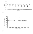
Figure 3 is charging and discharging curve of embodiments in the present invention. Infigure 3 , the horizontal axis is time/s, and the vertical axis is voltage/V. -
Figure 4 shows cycling performance curve of embodiments in the present invention. Infigure 4 , the horizontal axis is cycle number, and the vertical axis is energy density/WhL-1. - The following embodiments in combination with the figures are used to further illustrate the present invention.
- As shown in
figure 1 , the supercapacitor comprises one unit in example 1, comprisingpositive electrode collector 11,positive electrode chamber 12, separator 13,negative electrode chamber 14 andnegative electrode collector 15. - Graphite felt is employed as both positive and
negative chamber negative electrode chamber negative electrode collector Figure 3 shows the charging - discharging working curve of this supercapacitor.Figure 4 shows the cycling curve of 7000 times for this supercapacitor. It can be seen that this supercapacitor possesses higher capacity and excellent cycle performance. - Since both positive and negative electrode chamber are solid porous electrode, the micropores inside porous electrode are full of non - flowing positive and negative electrode liquid. Because the positive and negative electrode liquid respectively contains at least one positive and negative electrode electrochemical active material, so the electrochemical oxidation - reduction reaction mainly are conducted on the innner surface of positive and negative electrode chamber.
- As shown in
figure 2 , the supercapacitor combination comprises multiple - units in example 2, foam nickel is adopted aspositive electrode chamber 22 of supercapacitor, and the activated carbon is employed asnegative electrode chamber 24 of supercapacitor, the thickness of foam nickel is 2 mm, and the voidage is 90%, the thickness of activated carbon is 5 mm, and the voidage is 50%. 2M FeSO4/ Fe2(SO4)3 + 1M H2SO4 is used as positive electrode electrolyte, while 2M Ti2(SO4)3/TiOSO4 + 1M H2SO4 is used as negative electrode electrolyte. Anion exchange membrane is used as separator 23 of positive and negative electrode chamber, and nickel sheet is used ascollector negative electrode collector 25 is positive and negative dipolar type collector. - As shown in
figure 1 , the supercapacitor comprises one unit in example 3, consisting ofpositive electrode collector 11,positive electrode chamber 12, separator 13,negative chamber 14 andnegative electrode collector 15. - Carbon cloth is used as positive and
negative electrode chamber negative electrode chamber collector - As shown in
figure 1 , the supercapacitor comprises one unit in example 4, consisting ofpositive electrode collector 11,positive electrode chamber 12, separator 13,negative electrode chamber 14 andnegative electrode collector 15. - Polyaniline film is employed as positive and
negative electrode chamber negative electrode chamber negative electrode collector - As shown in
figure 1 , the supercapacitor combination comprises double electrode plate in example 4, consisting ofpositive electrode collector 21,positive electrode chamber 22, separator 23,negative electrode chamber 24, andnegative electrode collector 25. - Electric conductive plastic is employed as double electrode plate and
collector 25, positive andnegative electrode chamber
Claims (14)
- A supercapacitor based on liquid phase electrochemical active materials, which is characterized in that it comprises at lease one unit of positive electrode collector, positive electrode chamber, separator, negative electrode chamber and negative electrode collector, the positive electrode chamber is solid porous electrode, the micropores are filled with non - flowing positive electrode liquid in porous electrode, and the negative electrode chamber is also a solid porous electrode, the microproese of which are filled with non - flowing negative electrode liquid, the positive electrode liquid contains at least one positive electrode electrochemical active material, the electrochemical oxidation - reduction reaction mainly conducts on the inner surface, the negative electrode liquid contains at least one negative electrode electrochemical active material, the electrochemical oxidation reduction reaction mainly conducts on the inner surface of negative electrode.
The electrode materials used for positive and negative electrode chamber are electrochemical inert solids, and the aforementioned electrochemical inert solids are good electric conductors being chemically stable to positive and negative electrode liquid;
Positive and negative electrode collectors are designed to collect current, which is good electric conductor.
Positive electrode liquid contains at least one positive electrode electrochemical active material, and negative electrode liquid contains at least one negative electrode electrochemical active material;
The liquid phase of electrode liquid is selected from aqueous solution, non - aqueous organic solution, inorganic fused salt or organic fused salt. - The supercapacitor based on electrochemical active material in liquid phase as described in claim 1, which is characterized in that the aforementioned positive and negative electrode chambers and thereof electrode materials are electrochemical inert solids.
- The supercapacitor based on electrochemical active material in liquid phase as described in claim 1, which is characterized in that the aforementioned electrochemical inert solids are good electric conductors being chemically stable to positive or negative electrode liquid, which is selected from carbon material, inert or passivated metals or alloy materials and electric conductive polymer materials.
- The supercapacitor based on electrochemical active material in liquid phase as described in claim 1, which is characterized in that the aforementioned carbon material is selected from one of graphite, carbon black, carbon nanometer tube, activated carbon, amorphous carbon; inert or passivated metals are selected from inertized nickel, noble metals or alloy materials and electric conductive materials, the aforementioned electric conductive polymer materials are selected from one of aniline, thiophene, pyrrole, furan and their derivative polymers.
- The supercapacitor based on electrochemical active material in liquid phase as described in claim 1, which is characterized in that the thickness of positive and negative electrode chamber is 5 - 0.01 mm, respectively.
- The supercapacitor based on electrochemical active material in liquid phase as described in claim 1, which is characterized in that the aforementioned porous electrode material is porous electrode rich in micropore, which is selected from porous electrode comprised of thin micron or submicron sheet materials or porous electrode comprised composed of plenty of subtle sheet materials.
- The supercapacitor based on electrochemical active material in liquid phase as described in claim 1 or 6, which is characterized in that the aforementioned micropore size is less than 100µm.
- The supercapacitor based on electrochemical active material in liquid phase as described in claim 1 or 6, which is characterized in that the aforementioned micropore size is 100 - 0.1 µm.
- The supercapacitor based on electrochemical active material in liquid phase as described in claim 1 or 6, which is characterized in that the voidage of micropore is 99% - 10%.
- The supercapacitor based on electrochemical active material in liquid phase as described in claim 1, which is characterized in that the aforementioned positive electrode liquid contains positive electrode electrochemical active materials, which are selected from quadrivalent vanadium (VO+ +)/ quinquvalent vanadium (VO2 + ) redox agents; or are selected from redox agents containing Br-/Br2; or are selected from redox agents containing Fe+ +/Fe+ + +; or are selected from redox agents containing Ce+3/Ce+4.
- The supercapacitor based on electrochemical active material in liquid phase as described in claim 1 or 6, which is characterized in that the aforementioned negative electrode liquid contains negative electrode electrochemical active materials, which are selected from V+ + +/V+ + redox agents; or are selected from Cr+ + +/Cr+ + redox agents; or are selected from redox agents containing UO2 +/UO2 + +; or are selected from redox agents containing Ti+3/TiO+ +.
- The supercapacitor based on electrochemical active material in liquid phase as described in claim 1 or 6, which is characterized in that the separator is selected from homogeneous or non - homogeneous anion exchange membrane, homogeneous or non - homogenous cation exchange membrane or microporous membrane.
- The supercapacitor based on electrochemical active material in liquid phase as described in claim 1 or 12, which is characterized in that the thickness of separator is 2 - 0.01 mm.
- The supercapacitor based on electrochemical active material in liquid phase as described in claim 1 or 6, which is characterized in that the positive electrode collector or negative electrode collector is selected from metal materials or homogenous carbon materials.
Applications Claiming Priority (2)
| Application Number | Priority Date | Filing Date | Title |
|---|---|---|---|
| CNB2006100876251A CN100490033C (en) | 2006-06-05 | 2006-06-05 | Super capacitor based on electrochemical activated substance in liquid phase |
| PCT/CN2007/001155 WO2007140688A1 (en) | 2006-06-05 | 2007-04-10 | A supercapacitor based on electrochemistry active materials in liquid phase |
Publications (3)
| Publication Number | Publication Date |
|---|---|
| EP2026363A1 true EP2026363A1 (en) | 2009-02-18 |
| EP2026363A4 EP2026363A4 (en) | 2009-08-05 |
| EP2026363B1 EP2026363B1 (en) | 2011-06-01 |
Family
ID=37425415
Family Applications (1)
| Application Number | Title | Priority Date | Filing Date |
|---|---|---|---|
| EP07720728A Not-in-force EP2026363B1 (en) | 2006-06-05 | 2007-04-10 | A supercapacitor based on electrochemically active materials in a liquid phase |
Country Status (6)
| Country | Link |
|---|---|
| US (1) | US8094433B2 (en) |
| EP (1) | EP2026363B1 (en) |
| JP (1) | JP5095730B2 (en) |
| CN (1) | CN100490033C (en) |
| AT (1) | ATE511696T1 (en) |
| WO (1) | WO2007140688A1 (en) |
Families Citing this family (25)
| Publication number | Priority date | Publication date | Assignee | Title |
|---|---|---|---|---|
| JPS5990720A (en) * | 1982-11-16 | 1984-05-25 | Mazda Motor Corp | Intake device for engine |
| WO2010068929A2 (en) * | 2008-12-12 | 2010-06-17 | Ionix Power Systems | Active electrolyte electrochemical capacitor |
| WO2012037445A2 (en) | 2010-09-17 | 2012-03-22 | Drexel University | Novel applications for alliform carbon |
| JP5580327B2 (en) * | 2009-10-20 | 2014-08-27 | 国立大学法人東北大学 | Vanadium battery |
| US9752932B2 (en) | 2010-03-10 | 2017-09-05 | Drexel University | Tunable electro-optic filter stack |
| JP5743353B2 (en) * | 2010-04-02 | 2015-07-01 | インテル・コーポレーション | Charge storage device, method of manufacturing charge storage device, mobile electronic device, and microelectronic device |
| CN101880907B (en) * | 2010-07-07 | 2012-04-25 | 厦门大学 | Electrochemical levelling and polishing processing method with nanometer precision and device thereof |
| JP2012054035A (en) * | 2010-08-31 | 2012-03-15 | Tomomi Abe | Vanadium ion battery |
| CN102176380B (en) * | 2011-01-26 | 2016-06-01 | 中国海洋大学 | A kind of redox reaction electrochemical capacitor |
| CN102412383A (en) * | 2011-10-12 | 2012-04-11 | 厦门大学 | Nano-fluid battery |
| CN102543492B (en) * | 2012-02-16 | 2013-09-25 | 姜建国 | Preparation method of high-energy-density solid capacitor batteries |
| KR101939273B1 (en) | 2012-07-30 | 2019-01-16 | 삼성전자주식회사 | Electrode structure, method of manufacturing the same and energy storing device including the electrode structure |
| WO2014060886A1 (en) * | 2012-10-17 | 2014-04-24 | Ramot At Tel Aviv University Ltd | Super hybrid capacitor |
| JP2014130778A (en) * | 2012-12-28 | 2014-07-10 | Tohoku Techno Arch Co Ltd | Stationary vanadium redox battery |
| JP2014197521A (en) * | 2013-03-29 | 2014-10-16 | 株式会社 東北テクノアーチ | Vanadium solid salt battery and method for manufacturing the same |
| JP6083566B2 (en) * | 2013-04-18 | 2017-02-22 | 株式会社 東北テクノアーチ | Vanadium solid salt battery and manufacturing method thereof |
| JP5988268B2 (en) * | 2013-05-31 | 2016-09-07 | 株式会社 東北テクノアーチ | Vanadium solid salt battery |
| CN104576082B (en) * | 2015-01-16 | 2017-08-29 | 吉林大学 | Two pole rooms add the potassium ferricyanide and potassium ferrocyanide Asymmetric Supercapacitor and preparation method thereof respectively |
| US10166966B2 (en) | 2015-10-28 | 2019-01-01 | Toyota Motor Engineering & Manufacturing North America, Inc. | Hybrid vehicles and methods for providing electrical energy to motor-generators |
| CN107342620A (en) * | 2016-05-03 | 2017-11-10 | 程帅 | Supper-fast charging " charger baby " |
| CN109155204B (en) | 2016-05-20 | 2020-12-22 | 阿维科斯公司 | Electrode structure for supercapacitor |
| CN109155202B (en) * | 2016-05-20 | 2021-03-09 | 阿维科斯公司 | Multi-cell supercapacitor |
| EP3459097A4 (en) | 2016-05-20 | 2020-05-06 | AVX Corporation | WATER-FREE ELECTROLYT FOR AN ULTRA-CAPACITOR |
| MY194849A (en) | 2016-05-20 | 2022-12-19 | Kyocera Avx Components Corp | Ultracapacitor for use at high temperatures |
| JP6176760B2 (en) * | 2016-08-02 | 2017-08-09 | 株式会社 東北テクノアーチ | Vanadium solid salt battery |
Family Cites Families (15)
| Publication number | Priority date | Publication date | Assignee | Title |
|---|---|---|---|---|
| JPH06188005A (en) * | 1992-01-13 | 1994-07-08 | Kashimakita Kyodo Hatsuden Kk | Redox battery |
| JP3446239B2 (en) * | 1993-03-30 | 2003-09-16 | 株式会社デンソー | Rewindable battery |
| AU696452B2 (en) * | 1993-11-17 | 1998-09-10 | Jd Holding Inc. | Stabilised electrolyte solutions, methods of preparation thereof and redox cells and batteries containing stabilised electrolyte solutions |
| FR2759211B1 (en) | 1997-02-06 | 1999-04-30 | Electricite De France | DOUBLE LAYER TYPE SUPERCAPACITOR COMPRISING A LIQUID ORGANIC ELECTROLYTE |
| EP0935265A3 (en) * | 1998-02-09 | 2002-06-12 | Wilson Greatbatch Ltd. | Thermal spray coated substrate for use in an electrical energy storage device and method |
| JPH11329474A (en) * | 1998-05-19 | 1999-11-30 | Mitsui Eng & Shipbuild Co Ltd | Redox battery or redox capacitor and method of manufacturing the same |
| JP2001093560A (en) * | 1999-09-27 | 2001-04-06 | Kashimakita Kyodo Hatsuden Kk | Redox (reduction-oxidation) flow battery |
| JP2001102080A (en) * | 1999-09-30 | 2001-04-13 | Kashimakita Kyodo Hatsuden Kk | Redox cell |
| US6426863B1 (en) * | 1999-11-25 | 2002-07-30 | Lithium Power Technologies, Inc. | Electrochemical capacitor |
| US6356433B1 (en) * | 2000-03-03 | 2002-03-12 | The Regents Of The University Of California | Conducting polymer ultracapacitor |
| KR100377302B1 (en) * | 2000-10-25 | 2003-03-26 | 김광범 | The method of manufacturing a electrode of hydrous ruthenium oxide thin film electrode and the installation thereof |
| JP2004513529A (en) * | 2000-11-09 | 2004-04-30 | エフオーシー フランケンブルク オイル カンパニー エスト. | Supercapacitor and method of manufacturing the supercapacitor |
| US20020110732A1 (en) * | 2000-12-20 | 2002-08-15 | Polystor Corporation | Battery cell fabrication process |
| CN2615840Y (en) * | 2003-04-11 | 2004-05-12 | 江苏双登电源有限公司 | Electrochemical super capacitor |
| CN100547707C (en) | 2004-10-25 | 2009-10-07 | 中国科学院电工研究所 | A kind of supercapacitor and its manufacturing method |
-
2006
- 2006-06-05 CN CNB2006100876251A patent/CN100490033C/en not_active Expired - Fee Related
-
2007
- 2007-04-10 JP JP2009513534A patent/JP5095730B2/en not_active Expired - Fee Related
- 2007-04-10 AT AT07720728T patent/ATE511696T1/en not_active IP Right Cessation
- 2007-04-10 US US12/303,193 patent/US8094433B2/en not_active Expired - Fee Related
- 2007-04-10 WO PCT/CN2007/001155 patent/WO2007140688A1/en not_active Ceased
- 2007-04-10 EP EP07720728A patent/EP2026363B1/en not_active Not-in-force
Also Published As
| Publication number | Publication date |
|---|---|
| US8094433B2 (en) | 2012-01-10 |
| WO2007140688A1 (en) | 2007-12-13 |
| JP5095730B2 (en) | 2012-12-12 |
| EP2026363B1 (en) | 2011-06-01 |
| US20090190286A1 (en) | 2009-07-30 |
| JP2009540549A (en) | 2009-11-19 |
| CN1866427A (en) | 2006-11-22 |
| ATE511696T1 (en) | 2011-06-15 |
| CN100490033C (en) | 2009-05-20 |
| EP2026363A4 (en) | 2009-08-05 |
Similar Documents
| Publication | Publication Date | Title |
|---|---|---|
| EP2026363B1 (en) | A supercapacitor based on electrochemically active materials in a liquid phase | |
| Yoshino et al. | Development of a lithium-type advanced energy storage device | |
| KR101384663B1 (en) | Supercapacitor and electrochemical apparatus for water purification using the same | |
| CN100547707C (en) | A kind of supercapacitor and its manufacturing method | |
| Nandi et al. | Rare earth based nanocomposite materials for prominent performance supercapacitor: a review | |
| CN101261899A (en) | A high working voltage super capacitor and its making method | |
| CN102176380A (en) | Oxidation-reduction reaction electrochemical capacitor | |
| Singh et al. | Enhanced energy density of quasi‐solid‐state supercapacitor based on activated carbon electrode derived from honeycomb and gel polymer electrolyte with redox‐additive methylene blue | |
| Li et al. | Tuning the Mechanical and Electrical Properties of Porous Electrodes for Architecting 3D Microsupercapacitors with Batteries‐Level Energy | |
| Lin et al. | Research Progress of Zinc Bromine Flow Battery. | |
| CN102856080B (en) | A kind of super capacitor material based on nano porous metal conducting polymer and preparation method thereof | |
| CN104103429A (en) | Poly (carboxyl indole) membrane electrode with supercapacitor nanowire structure and preparation method thereof | |
| CN107591591A (en) | Open half air fuel type faintly acid MH secondary battery | |
| Yu et al. | Emerging molten salts based electrochemical energy technologies | |
| Emmett et al. | Increasing Charge Transfer at the Liquid− Solid Interface Using Electrodes Modified with Redox Mediators | |
| CN101894686A (en) | Super capacitor battery | |
| Chaudhary et al. | Energy storage devices: supercapacitor, fuel cells, rechargeable batteries, PV/solar cells, hydrogen storage devices, and semiconductors | |
| JP2001085063A (en) | Electrochemical capacitor | |
| CN103474250A (en) | Super capacitor and manufacturing method thereof | |
| TW201327596A (en) | Energy storage device | |
| JP5109323B2 (en) | Electrode for electrochemical device, method for producing the same, and electrochemical device | |
| KR102591528B1 (en) | Electrode for zinc-bromine battery and zinc-bromine battery comprising the same | |
| CN115240991B (en) | A method for manufacturing an ionic supercapacitor based on electroactive ionic liquid | |
| CN118156466A (en) | A hydrangea-shaped multi-level structure CoAl-LDH@CoF2 composite material and its preparation method and application | |
| JP2002025865A (en) | Electric double-layer capacitor |
Legal Events
| Date | Code | Title | Description |
|---|---|---|---|
| PUAI | Public reference made under article 153(3) epc to a published international application that has entered the european phase |
Free format text: ORIGINAL CODE: 0009012 |
|
| 17P | Request for examination filed |
Effective date: 20081217 |
|
| AK | Designated contracting states |
Kind code of ref document: A1 Designated state(s): AT BE BG CH CY CZ DE DK EE ES FI FR GB GR HU IE IS IT LI LT LU LV MC MT NL PL PT RO SE SI SK TR |
|
| AX | Request for extension of the european patent |
Extension state: AL BA HR MK RS |
|
| A4 | Supplementary search report drawn up and despatched |
Effective date: 20090707 |
|
| RIC1 | Information provided on ipc code assigned before grant |
Ipc: H01G 9/04 20060101ALI20090701BHEP Ipc: H01G 9/058 20060101ALI20090701BHEP Ipc: H01G 9/155 20060101AFI20080221BHEP |
|
| 17Q | First examination report despatched |
Effective date: 20090820 |
|
| GRAP | Despatch of communication of intention to grant a patent |
Free format text: ORIGINAL CODE: EPIDOSNIGR1 |
|
| RTI1 | Title (correction) |
Free format text: A SUPERCAPACITOR BASED ON ELECTROCHEMICALLY ACTIVE MATERIALS IN A LIQUID PHASE |
|
| DAX | Request for extension of the european patent (deleted) | ||
| GRAS | Grant fee paid |
Free format text: ORIGINAL CODE: EPIDOSNIGR3 |
|
| GRAA | (expected) grant |
Free format text: ORIGINAL CODE: 0009210 |
|
| AK | Designated contracting states |
Kind code of ref document: B1 Designated state(s): AT BE BG CH CY CZ DE DK EE ES FI FR GB GR HU IE IS IT LI LT LU LV MC MT NL PL PT RO SE SI SK TR |
|
| REG | Reference to a national code |
Ref country code: GB Ref legal event code: FG4D |
|
| REG | Reference to a national code |
Ref country code: CH Ref legal event code: EP |
|
| REG | Reference to a national code |
Ref country code: IE Ref legal event code: FG4D |
|
| REG | Reference to a national code |
Ref country code: DE Ref legal event code: R096 Ref document number: 602007014965 Country of ref document: DE Effective date: 20110714 |
|
| REG | Reference to a national code |
Ref country code: NL Ref legal event code: VDEP Effective date: 20110601 |
|
| PG25 | Lapsed in a contracting state [announced via postgrant information from national office to epo] |
Ref country code: SE Free format text: LAPSE BECAUSE OF FAILURE TO SUBMIT A TRANSLATION OF THE DESCRIPTION OR TO PAY THE FEE WITHIN THE PRESCRIBED TIME-LIMIT Effective date: 20110601 Ref country code: LT Free format text: LAPSE BECAUSE OF FAILURE TO SUBMIT A TRANSLATION OF THE DESCRIPTION OR TO PAY THE FEE WITHIN THE PRESCRIBED TIME-LIMIT Effective date: 20110601 |
|
| PG25 | Lapsed in a contracting state [announced via postgrant information from national office to epo] |
Ref country code: FI Free format text: LAPSE BECAUSE OF FAILURE TO SUBMIT A TRANSLATION OF THE DESCRIPTION OR TO PAY THE FEE WITHIN THE PRESCRIBED TIME-LIMIT Effective date: 20110601 Ref country code: ES Free format text: LAPSE BECAUSE OF FAILURE TO SUBMIT A TRANSLATION OF THE DESCRIPTION OR TO PAY THE FEE WITHIN THE PRESCRIBED TIME-LIMIT Effective date: 20110912 Ref country code: CY Free format text: LAPSE BECAUSE OF FAILURE TO SUBMIT A TRANSLATION OF THE DESCRIPTION OR TO PAY THE FEE WITHIN THE PRESCRIBED TIME-LIMIT Effective date: 20110601 Ref country code: SI Free format text: LAPSE BECAUSE OF FAILURE TO SUBMIT A TRANSLATION OF THE DESCRIPTION OR TO PAY THE FEE WITHIN THE PRESCRIBED TIME-LIMIT Effective date: 20110601 Ref country code: AT Free format text: LAPSE BECAUSE OF FAILURE TO SUBMIT A TRANSLATION OF THE DESCRIPTION OR TO PAY THE FEE WITHIN THE PRESCRIBED TIME-LIMIT Effective date: 20110601 Ref country code: GR Free format text: LAPSE BECAUSE OF FAILURE TO SUBMIT A TRANSLATION OF THE DESCRIPTION OR TO PAY THE FEE WITHIN THE PRESCRIBED TIME-LIMIT Effective date: 20110902 Ref country code: LV Free format text: LAPSE BECAUSE OF FAILURE TO SUBMIT A TRANSLATION OF THE DESCRIPTION OR TO PAY THE FEE WITHIN THE PRESCRIBED TIME-LIMIT Effective date: 20110601 |
|
| PG25 | Lapsed in a contracting state [announced via postgrant information from national office to epo] |
Ref country code: NL Free format text: LAPSE BECAUSE OF FAILURE TO SUBMIT A TRANSLATION OF THE DESCRIPTION OR TO PAY THE FEE WITHIN THE PRESCRIBED TIME-LIMIT Effective date: 20110601 Ref country code: BE Free format text: LAPSE BECAUSE OF FAILURE TO SUBMIT A TRANSLATION OF THE DESCRIPTION OR TO PAY THE FEE WITHIN THE PRESCRIBED TIME-LIMIT Effective date: 20110601 |
|
| PG25 | Lapsed in a contracting state [announced via postgrant information from national office to epo] |
Ref country code: EE Free format text: LAPSE BECAUSE OF FAILURE TO SUBMIT A TRANSLATION OF THE DESCRIPTION OR TO PAY THE FEE WITHIN THE PRESCRIBED TIME-LIMIT Effective date: 20110601 Ref country code: PT Free format text: LAPSE BECAUSE OF FAILURE TO SUBMIT A TRANSLATION OF THE DESCRIPTION OR TO PAY THE FEE WITHIN THE PRESCRIBED TIME-LIMIT Effective date: 20111003 Ref country code: IS Free format text: LAPSE BECAUSE OF FAILURE TO SUBMIT A TRANSLATION OF THE DESCRIPTION OR TO PAY THE FEE WITHIN THE PRESCRIBED TIME-LIMIT Effective date: 20111001 Ref country code: CZ Free format text: LAPSE BECAUSE OF FAILURE TO SUBMIT A TRANSLATION OF THE DESCRIPTION OR TO PAY THE FEE WITHIN THE PRESCRIBED TIME-LIMIT Effective date: 20110601 |
|
| PG25 | Lapsed in a contracting state [announced via postgrant information from national office to epo] |
Ref country code: SK Free format text: LAPSE BECAUSE OF FAILURE TO SUBMIT A TRANSLATION OF THE DESCRIPTION OR TO PAY THE FEE WITHIN THE PRESCRIBED TIME-LIMIT Effective date: 20110601 Ref country code: RO Free format text: LAPSE BECAUSE OF FAILURE TO SUBMIT A TRANSLATION OF THE DESCRIPTION OR TO PAY THE FEE WITHIN THE PRESCRIBED TIME-LIMIT Effective date: 20110601 Ref country code: PL Free format text: LAPSE BECAUSE OF FAILURE TO SUBMIT A TRANSLATION OF THE DESCRIPTION OR TO PAY THE FEE WITHIN THE PRESCRIBED TIME-LIMIT Effective date: 20110601 |
|
| PLBE | No opposition filed within time limit |
Free format text: ORIGINAL CODE: 0009261 |
|
| STAA | Information on the status of an ep patent application or granted ep patent |
Free format text: STATUS: NO OPPOSITION FILED WITHIN TIME LIMIT |
|
| 26N | No opposition filed |
Effective date: 20120302 |
|
| PG25 | Lapsed in a contracting state [announced via postgrant information from national office to epo] |
Ref country code: IT Free format text: LAPSE BECAUSE OF FAILURE TO SUBMIT A TRANSLATION OF THE DESCRIPTION OR TO PAY THE FEE WITHIN THE PRESCRIBED TIME-LIMIT Effective date: 20110601 |
|
| REG | Reference to a national code |
Ref country code: DE Ref legal event code: R097 Ref document number: 602007014965 Country of ref document: DE Effective date: 20120302 |
|
| PG25 | Lapsed in a contracting state [announced via postgrant information from national office to epo] |
Ref country code: DK Free format text: LAPSE BECAUSE OF FAILURE TO SUBMIT A TRANSLATION OF THE DESCRIPTION OR TO PAY THE FEE WITHIN THE PRESCRIBED TIME-LIMIT Effective date: 20110601 |
|
| PG25 | Lapsed in a contracting state [announced via postgrant information from national office to epo] |
Ref country code: MC Free format text: LAPSE BECAUSE OF NON-PAYMENT OF DUE FEES Effective date: 20120430 |
|
| REG | Reference to a national code |
Ref country code: CH Ref legal event code: PL |
|
| GBPC | Gb: european patent ceased through non-payment of renewal fee |
Effective date: 20120410 |
|
| REG | Reference to a national code |
Ref country code: IE Ref legal event code: MM4A |
|
| REG | Reference to a national code |
Ref country code: FR Ref legal event code: ST Effective date: 20121228 |
|
| PG25 | Lapsed in a contracting state [announced via postgrant information from national office to epo] |
Ref country code: GB Free format text: LAPSE BECAUSE OF NON-PAYMENT OF DUE FEES Effective date: 20120410 Ref country code: CH Free format text: LAPSE BECAUSE OF NON-PAYMENT OF DUE FEES Effective date: 20120430 Ref country code: IE Free format text: LAPSE BECAUSE OF NON-PAYMENT OF DUE FEES Effective date: 20120410 Ref country code: LI Free format text: LAPSE BECAUSE OF NON-PAYMENT OF DUE FEES Effective date: 20120430 |
|
| PG25 | Lapsed in a contracting state [announced via postgrant information from national office to epo] |
Ref country code: FR Free format text: LAPSE BECAUSE OF NON-PAYMENT OF DUE FEES Effective date: 20120430 |
|
| PG25 | Lapsed in a contracting state [announced via postgrant information from national office to epo] |
Ref country code: BG Free format text: LAPSE BECAUSE OF FAILURE TO SUBMIT A TRANSLATION OF THE DESCRIPTION OR TO PAY THE FEE WITHIN THE PRESCRIBED TIME-LIMIT Effective date: 20110901 |
|
| PG25 | Lapsed in a contracting state [announced via postgrant information from national office to epo] |
Ref country code: MT Free format text: LAPSE BECAUSE OF FAILURE TO SUBMIT A TRANSLATION OF THE DESCRIPTION OR TO PAY THE FEE WITHIN THE PRESCRIBED TIME-LIMIT Effective date: 20110601 |
|
| PG25 | Lapsed in a contracting state [announced via postgrant information from national office to epo] |
Ref country code: TR Free format text: LAPSE BECAUSE OF FAILURE TO SUBMIT A TRANSLATION OF THE DESCRIPTION OR TO PAY THE FEE WITHIN THE PRESCRIBED TIME-LIMIT Effective date: 20110601 |
|
| PG25 | Lapsed in a contracting state [announced via postgrant information from national office to epo] |
Ref country code: LU Free format text: LAPSE BECAUSE OF NON-PAYMENT OF DUE FEES Effective date: 20120410 |
|
| PG25 | Lapsed in a contracting state [announced via postgrant information from national office to epo] |
Ref country code: HU Free format text: LAPSE BECAUSE OF FAILURE TO SUBMIT A TRANSLATION OF THE DESCRIPTION OR TO PAY THE FEE WITHIN THE PRESCRIBED TIME-LIMIT Effective date: 20070410 |
|
| PGFP | Annual fee paid to national office [announced via postgrant information from national office to epo] |
Ref country code: DE Payment date: 20140429 Year of fee payment: 8 |
|
| REG | Reference to a national code |
Ref country code: DE Ref legal event code: R119 Ref document number: 602007014965 Country of ref document: DE |
|
| PG25 | Lapsed in a contracting state [announced via postgrant information from national office to epo] |
Ref country code: DE Free format text: LAPSE BECAUSE OF NON-PAYMENT OF DUE FEES Effective date: 20151103 |