EP2026042A1 - In-Line-Messvorrichtungen und Verfahren zum Ausgleich von Messfehlern in In-Line-Messvorrichtungen - Google Patents
In-Line-Messvorrichtungen und Verfahren zum Ausgleich von Messfehlern in In-Line-Messvorrichtungen Download PDFInfo
- Publication number
- EP2026042A1 EP2026042A1 EP08168408A EP08168408A EP2026042A1 EP 2026042 A1 EP2026042 A1 EP 2026042A1 EP 08168408 A EP08168408 A EP 08168408A EP 08168408 A EP08168408 A EP 08168408A EP 2026042 A1 EP2026042 A1 EP 2026042A1
- Authority
- EP
- European Patent Office
- Prior art keywords
- mixture
- measuring tube
- oscillation
- measuring
- tube
- Prior art date
- Legal status (The legal status is an assumption and is not a legal conclusion. Google has not performed a legal analysis and makes no representation as to the accuracy of the status listed.)
- Withdrawn
Links
Images


Classifications
-
- G—PHYSICS
- G01—MEASURING; TESTING
- G01F—MEASURING VOLUME, VOLUME FLOW, MASS FLOW OR LIQUID LEVEL; METERING BY VOLUME
- G01F1/00—Measuring the volume flow or mass flow of fluid or fluent solid material wherein the fluid passes through a meter in a continuous flow
- G01F1/76—Devices for measuring mass flow of a fluid or a fluent solid material
- G01F1/78—Direct mass flowmeters
- G01F1/80—Direct mass flowmeters operating by measuring pressure, force, momentum, or frequency of a fluid flow to which a rotational movement has been imparted
- G01F1/84—Coriolis or gyroscopic mass flowmeters
- G01F1/845—Coriolis or gyroscopic mass flowmeters arrangements of measuring means, e.g., of measuring conduits
- G01F1/8468—Coriolis or gyroscopic mass flowmeters arrangements of measuring means, e.g., of measuring conduits vibrating measuring conduits
- G01F1/849—Coriolis or gyroscopic mass flowmeters arrangements of measuring means, e.g., of measuring conduits vibrating measuring conduits having straight measuring conduits
-
- G—PHYSICS
- G01—MEASURING; TESTING
- G01F—MEASURING VOLUME, VOLUME FLOW, MASS FLOW OR LIQUID LEVEL; METERING BY VOLUME
- G01F1/00—Measuring the volume flow or mass flow of fluid or fluent solid material wherein the fluid passes through a meter in a continuous flow
- G01F1/74—Devices for measuring flow of a fluid or flow of a fluent solid material in suspension in another fluid
-
- G—PHYSICS
- G01—MEASURING; TESTING
- G01F—MEASURING VOLUME, VOLUME FLOW, MASS FLOW OR LIQUID LEVEL; METERING BY VOLUME
- G01F1/00—Measuring the volume flow or mass flow of fluid or fluent solid material wherein the fluid passes through a meter in a continuous flow
- G01F1/76—Devices for measuring mass flow of a fluid or a fluent solid material
- G01F1/78—Direct mass flowmeters
- G01F1/80—Direct mass flowmeters operating by measuring pressure, force, momentum, or frequency of a fluid flow to which a rotational movement has been imparted
- G01F1/84—Coriolis or gyroscopic mass flowmeters
- G01F1/8409—Coriolis or gyroscopic mass flowmeters constructional details
- G01F1/8413—Coriolis or gyroscopic mass flowmeters constructional details means for influencing the flowmeter's motional or vibrational behaviour, e.g., conduit support or fixing means, or conduit attachments
- G01F1/8418—Coriolis or gyroscopic mass flowmeters constructional details means for influencing the flowmeter's motional or vibrational behaviour, e.g., conduit support or fixing means, or conduit attachments motion or vibration balancing means
-
- G—PHYSICS
- G01—MEASURING; TESTING
- G01F—MEASURING VOLUME, VOLUME FLOW, MASS FLOW OR LIQUID LEVEL; METERING BY VOLUME
- G01F1/00—Measuring the volume flow or mass flow of fluid or fluent solid material wherein the fluid passes through a meter in a continuous flow
- G01F1/76—Devices for measuring mass flow of a fluid or a fluent solid material
- G01F1/78—Direct mass flowmeters
- G01F1/80—Direct mass flowmeters operating by measuring pressure, force, momentum, or frequency of a fluid flow to which a rotational movement has been imparted
- G01F1/84—Coriolis or gyroscopic mass flowmeters
- G01F1/8409—Coriolis or gyroscopic mass flowmeters constructional details
- G01F1/8431—Coriolis or gyroscopic mass flowmeters constructional details electronic circuits
-
- G—PHYSICS
- G01—MEASURING; TESTING
- G01F—MEASURING VOLUME, VOLUME FLOW, MASS FLOW OR LIQUID LEVEL; METERING BY VOLUME
- G01F1/00—Measuring the volume flow or mass flow of fluid or fluent solid material wherein the fluid passes through a meter in a continuous flow
- G01F1/76—Devices for measuring mass flow of a fluid or a fluent solid material
- G01F1/78—Direct mass flowmeters
- G01F1/80—Direct mass flowmeters operating by measuring pressure, force, momentum, or frequency of a fluid flow to which a rotational movement has been imparted
- G01F1/84—Coriolis or gyroscopic mass flowmeters
- G01F1/8409—Coriolis or gyroscopic mass flowmeters constructional details
- G01F1/8436—Coriolis or gyroscopic mass flowmeters constructional details signal processing
-
- G—PHYSICS
- G01—MEASURING; TESTING
- G01F—MEASURING VOLUME, VOLUME FLOW, MASS FLOW OR LIQUID LEVEL; METERING BY VOLUME
- G01F15/00—Details of, or accessories for, apparatus of groups G01F1/00 - G01F13/00 insofar as such details or appliances are not adapted to particular types of such apparatus
- G01F15/02—Compensating or correcting for variations in pressure, density or temperature
- G01F15/022—Compensating or correcting for variations in pressure, density or temperature using electrical means
- G01F15/024—Compensating or correcting for variations in pressure, density or temperature using electrical means involving digital counting
Definitions
- the invention relates to an In-line measuring device having a transducer of the vibratory-type, especially a Coriolis mass-flow/density measuring device for a medium, especially a two, or more, phase medium flowing in a pipeline, as well as a method for producing by means of such a vibratory transducer a measured value representing a physical, measured quantity of the medium, for example a mass flow rate, a density and/or a viscosity. Further, the invention relates to a method for compensation, in such In-line measuring devices, measurement errors caused by two-phase or multi-phase mixtures.
- the measurement of physical parameters of a medium flowing in a pipeline parameters such as e.g. the mass flow rate, density and/or viscosity, such inline measuring devices, especially Coriolis mass flow measuring devices, are used, which bring about reaction forces in the medium, such as e.g. Coriolis forces corresponding to the mass flow rate, inertial forces corresponding to the density, or frictional forces corresponding to the viscosity, etc., by means of a transducer of the vibratory-type - hereinafter vibratory transducer - inserted into the course of the pipeline carrying the medium and traversed during operation by the medium, and by means of a measurement and operating circuit connected therewith.
- parameters such as e.g. the mass flow rate, density and/or viscosity, such inline measuring devices, especially Coriolis mass flow measuring devices, are used, which bring about reaction forces in the medium, such as e.g. Coriolis forces corresponding to the mass flow rate, inertial forces corresponding to the density, or frictional forces
- the measuring devices then produce a measurement signal representing the particular mass flow rate, the particular viscosity and/or the particular density of the medium.
- Inline measuring devices of this type utilizing a vibratory transducer, as well as their manner of operation, are known per se to those skilled in the art and are described in detail in e.g.
- WO-A 03/095950 WO-A 03/095949 , WO-A 03/076880 , WO-A 02/37063 , WO-A 01/33174 , WO-A 00/57141 , WO-A 99/39164 , WO-A 98/07009 , WO-A 95/16897 , WO-A 88/03261 , US 2003/0208325 , US-B 6,745,135 , US-B 6,691,583 , US-B 6,651,513 , US-B 6,636,815 , US-B 6,513,393 , US-B 6,505,519 , US-B 6,311,136 , US-A 6,006,609 , US-A 5,869,770 , US-A 5,796,011 , US-A 5,616,868 , US-A 5,602,346 , US-A 5,602,345 , US-A 5,531,126 ,
- the vibratory transducers include at least one measuring tube with a straight tube segment held in a, for example, tubular or box-shaped, support frame.
- the tube segment is caused to vibrate, driven by an electromechanical exciter arrangement.
- the vibratory transducers additionally include an electrophysical sensor arrangement reacting to motions of the tube segment.
- the measurement of the mass flow rate of a medium flowing in a pipeline rests, for example, on having the medium flow through the measuring tube inserted into the pipeline and oscillating during operation laterally to a measuring tube axis, whereby Coriolis forces are induced in the medium.
- the oscillations of the measuring tube are, to this end, registered by means of two oscillation sensors of the above-mentioned sensor arrangement separated from one another along the length of the measuring tube and are transformed into oscillation measurement signals, from whose phase shift relative to one another the mass flow rate is derived.
- the instantaneous density of the flowing medium can also be measured by means of such inline measuring devices, and, indeed, on the basis of a frequency of at least one of the oscillation measurement signals delivered from the sensor arrangement.
- a temperature of the medium is directly measured in suitable manner, for example by means of a temperature sensor arranged on the measuring tube.
- straight measuring tubes can, as is known, upon being excited to torsional oscillations about a torsional oscillation axis extending essentially parallel to, or coinciding with, the longitudinal axis of the measuring tube, effect that radial shearing forces are produced in the medium as it flows through the tube, whereby significant oscillation energy is withdrawn from the torsional oscillations and dissipated in the medium.
- a considerable damping of the torsional oscillations of the oscillating measuring tube occurs, so that, additionally, electrical exciting power must be added, in order to maintain the torsional oscillations.
- the vibratory transducer can also be used to determine, at least approximately, a viscosity of the medium; compare, in this connection also US-A 4,524,610 , US-A 5,253,533 , US-A 6,006,609 or US-B 6,651,513 .
- inline measuring devices with a vibratory transducer are widely used in industry for mass flow and density measurement of fluids, especially single-phase liquids or gases of such devices.
- a vibratory transducer especially Coriolis flowmeters
- the accuracies of such devices may decrease significantly, if a second phase, i.e. a plurality of gas bubbles, is mixed with the processed liquid such that the measured medium is not a pure single-phase flow.
- a second phase i.e. a plurality of gas bubbles
- the oscillation measurement signals can be completely unusable for the measurement of the desired physical parameters, without the use of auxiliary measures, this in spite of keeping the viscosity and density in the individual phases of the medium, as well as also the mass flow rate, practically constant and/or appropriately taking them into consideration.
- Such inhomogeneous media can, for example, be liquids, into which, as is e.g. practically unavoidable in dosing or bottling processes, a gas, especially air, present in the pipeline is entrained or out of which a dissolved medium, e.g. carbon dioxide, outgases and leads to foam formation.
- a dissolved medium e.g. carbon dioxide
- steam can be named.
- both JP-A 10-281846 , US-B 6,311,136 and US-B 6,505,519 describe a correction of the flow rate measurement, especially the mass flow rate measurement, based on the oscillation measurement signals, which correction rests especially on the evaluation of deficits between a highly accurately measured, actual medium density and an apparent medium density determined by means of Coriolis mass flow measuring devices during operation.
- a correction method for mass flow errors This does also base on said bubble theory essentially, and, thus, uses density errors, detected between a reference and an apparent density, to compensate mass flow errors caused by two-phase or multi-phase mixture.
- classifiers of the oscillation measurement signals are proposed for this.
- the classifiers can, for example, be designed as a Kohonen map or neural network, and the correction is made either on the basis of some few parameters, especially the mass flow rate and the density measured during operation, as well as other features derived therefrom, or also using an interval of the oscillation measurement signals encompassing one or more oscillation periods.
- the use of such a classifier brings, for example, the advantage that, in comparison to conventional Coriolis mass flow/density meters, no, or only very slight, changes have to be made at the vibratory transducer, in terms of mechanical construction, the exciter arrangement or the operating circuit driving such, which are specially adapted for the particular application.
- a considerable disadvantage of such classifiers includes, among others, that, in comparison to conventional Coriolis mass flow measuring devices, considerable changes are required in the area of the measured value production, above all with regards to the analog-to-digital transducer being used and the microprocessors.
- required for such a signal evaluation for example, in the digitizing of the oscillation measurement signals, which can exhibit an oscillation frequency of about 80 Hz, is a sampling rate of about 55 kHz or more, in order to obtain a sufficient accuracy.
- the oscillation measurement signals have to be samples with a sampling ratio of far above 600:1.
- the firmware stored and executed in the digital measurement circuit is correspondingly complex.
- a further disadvantage of such classifiers is that they must be trained and correspondingly validated for the conditions of measurement actually existing during operation of the vibratory transducer, be it regarding the particulars of the installation, the medium to be measured and its usually variable properties, or other factors influencing the accuracy of measurement. Because of the high complexity of the interplay of all these factors, the training and its validation can occur ultimately only on site and individually for each vibratory transducer, this in turn meaning a considerable effort for the startup of the vibratory transducer.
- the measuring tubes might have a curved shape, in which case the problem cannot always be solved satisfactorily by an adapting of the installation orientation anyway. It has, moreover, been found in this case that the aforementioned corruptions of the measurement signal are not necessarily prevented with certainty by the use of a vertically installed, straight measuring tube anyway.
- An object of the invention is, therefore, to provide a corresponding inline measuring device, especially a Coriolis mass flow measuring device, that is suited for measuring a physical, measured quantity, especially mass flow rate, density and/or viscosity, very accurately, even in the case of inhomogeneous, especially two, or more, phase media, and, indeed, especially desirably with a measurement error of less than 10% referenced to the actual value of the measured quantity.
- a further object is to provide corresponding methods for producing a corresponding measured value.
- the invention resides in a method for measuring at least on parameter of a two-, or multi-phase mixture flowing in a pipeline, by means of an inline measuring device including a measurement transducer of the vibration-type, and a measuring device electronics electrically coupled with said measurement transducer, said mixture consisting of at least one first mixture phase and at least one second mixture phase.
- the invention resides in a method for determining a concentration of at least one phase of a mixture consisting of at least one first mixture phase and at least one second mixture phase, said mixture flowing in a pipeline, which is in communication with at least one measuring tube of an inline measuring device.
- the method comprises a step of conducting the mixture to be measured within at least one measuring tube of said measurement transducer, with the measuring tube being in communication with the pipeline.
- the method comprises a step of causing at least one of said first and second mixture phases, currently within said measuring tube, to move relative to the measuring tube.
- the relative motions of said at least one of the first and second mixture phases stimulate said at last one measuring tube to vibrate within at least one of a plurality of instantaneous natural eigenmodes of said at least one measuring tube conducting said mixture.
- the method comprises a step of feeding an exciter arrangement with an excitation signal, said exciter arrangement being adapted to impart motion to said at least one measuring tube, said excitation signal including at least a first excitation signal component corresponding to a first one of a plurality of natural eigenmodes of said at least one measuring tube conducting said mixture.
- the method comprises a step of vibrating said at least one measuring tube within said first one of said plurality of natural eigenmodes and within a second one of said plurality of natural eigenmodes of said at least one measuring tube conducting said mixture. At least said second natural eigenmode is stimulated, at least partially, due to motions of at least one of said first and second mixture phase within said measuring tube relative to said measuring tube.
- the method comprises a step of sensing vibrations of the measuring tube conducting said mixture and generating at least one oscillation measurement signal representing oscillations of the vibrating measuring tube.
- the at least one oscillation measurement signal includes at least a first measurement signal component corresponding to said first natural eigenmode of said at least one measuring tube conducting said mixture.
- the at least one oscillation measurement signal includes at least a second measurement signal component corresponding to said second one of said plurality of natural eigenmodes of said at least one measuring tube conducting said mixture.
- the method comprises a step of using at least said first and second measurement signal components for generating at least one measured value representing said at least on parameter to be measured.
- the at least one parameter may the concentration of at least the one phase of the mixture and the at least one measured value may said concentration value representing the concentration to be measured.
- the method comprises a step of using at least said first measurement signal components and said excitation signal for generating at least one measured value representing said at least on parameter to be measured.
- the method the second natural eigenmode the measurement tube vibrating is essentially not stimulated by the exciter arrangement at least temporary.
- the excitation signal is substantially devoid of any excitation signal components, which correspond to said second natural eigenmode stimulated due to said relative motion of said at least one first mixture phase and said at least one second mixture phase within the measuring tube, and/or which would excite said second natural eigenmode via said exciter arrangement.
- the method further includes a step of flowing said mixture through said at least one measuring tube.
- the method further comprises a step of vibrating said at least one measuring tube includes, at least temporary, a step of driving said measurement tube to oscillate within a driving mode for causing Coriolis forces within the mixture flowing through said measuring tube, said driving mode having at least one oscillation frequency that equals an instantaneous resonance frequency of said first natural eigenmode.
- the instantaneous resonance frequency of said first natural eigenmode may different from an instantaneous resonance frequency of said second eigenmode,
- At least the second natural eigenmode has an instantaneous resonance frequency depending on said mixture currently within said measuring tube, and wherein the second measurement signal component of the oscillation measurement signal has an instantaneous signal frequency corresponding with said instantaneous resonance frequency of said second natural eigenmode, said method further comprising a step of using said instantaneous signal frequency of said second measurement signal component for generating said measured value.
- the first natural eigenmode of the measuring tube may have also an instantaneous resonance frequency depending on said mixture currently within said measuring tube.
- At least the instantaneous resonance frequency of said second natural eigenmode may vary in time due to at least one of: relative motion of said first mixture and second mixture phases, changes in distribution of at least one of said first mixture and second mixture phases of the mixture within said measuring tube, and changes in a concentration of at least one of said first mixture and second mixture phases of the mixture.
- the instantaneous resonance frequency of said first natural eigenmode may different from an instantaneous resonance frequency of said second eigenmode.
- Said instantaneous signal frequency of said second measurement signal component may further used for selecting said second measurement signal component from said oscillation measurement signal.
- the first excitation signal component causes said measuring tube to vibrate in said first natural eigenmode with an oscillation amplitude depending at least on an amplitude of said first excitation signal component fed to the exciter arrangement.
- At least the oscillations of the measuring tube within said second natural eigenmode have an instantaneous oscillation amplitude depending on said mixture currently within said measuring tube, and wherein at least said second measurement signal component of the oscillation measurement signal has an instantaneous signal amplitude corresponding with said instantaneous oscillation amplitude of said oscillation of the measuring tube within said second natural eigenmode, said method further comprising a step of using said instantaneous signal amplitude of said second measurement signal component for generating said measured value.
- the oscillation amplitude of said oscillations of the measuring tube within the first natural eigenmode depends also on said mixture within said measuring tube.
- the method further comprises a step of using said signal amplitude of the second measurement signal component for selecting said second measurement signal component from the oscillation measurement signal.
- a first oscillation factor which represents a relation between said oscillation amplitude of said first natural eigenmode and said signal amplitude of said first excitation signal component causing said measuring tube to vibrate in said first natural eigenmode, may different from a second oscillation factor, which represents a relation between said oscillation amplitude of said second natural eigenmode and a signal amplitude of a second excitation signal component of the excitation signal having a signal frequency corresponding with the instantaneous resonance frequency of said second natural eigenmode.
- the first oscillation factor may represent a ratio of said oscillation amplitude corresponding with the first natural eigenmode normalized to said signal amplitude of the first excitation signal component
- the second oscillation factor may represent a ratio of said oscillation amplitude corresponding with the second natural eigenmode normalized to said signal amplitude of the second excitation signal component.
- the method may comprise a step of adjusting said excitation signal such that said first oscillation factor is less than said second oscillation factor.
- the signal amplitude of said second excitation signal component of the excitation signal may essentially zero.
- a signal-to-noise ratio of said second excitation signal component may less than two.
- the excitation signal fed to said exciter arrangement, may include at least a third signal component corresponding to a third one of a plurality of natural eigenmodes of said at least one measuring tube conducting said mixture.
- This third excitation signal component may cause the measuring tube to vibrate in said third natural eigenmode with an oscillation amplitude depending at least on an amplitude of said third excitation signal component fed to the exciter arrangement.
- the method further comprises further comprising a step of causing said at least one first mixture phase and said at least one second mixture phase, currently within said measuring tube, to move relative to each other.
- the step of causing relative motion of said at least one first mixture phase and said at least one second mixture phase may further comprise a step of flowing said mixture through said at least one measuring tube.
- the relative motions of said at least one first mixture phase and said at least one second mixture phase may stimulate said at last one measuring tube to vibrate within said at least one of a plurality of instantaneous natural eigenmodes of said at least one measuring tube conducting said mixture.
- the method further comprises steps of selecting from said excitation signal said first excitation signal component, and using at least said first excitation signal component for generating said at least one measured value.
- the method further comprises steps of determining from said excitation signal a current value representing a current of at least a portion of said excitation signal; and using said current value for generating said measured value.
- the method further comprises steps of selecting from said excitation signal said first excitation signal component, and using at least said first excitation signal component for generating said at least one measured value.
- one of said at least one first mixture and second mixture phases of the mixture may gaseous and/or one of said at least one first mixture and second mixture phases of the mixture may liquid and/or one of said at least one first mixture and second mixture phases of the mixture is solid, i.e. granular.
- the mixture may selected from a group consisting of: powder, granulate, aerated oil, aerated water, aerosol, spray, slurry, pulp, paste.
- the physical parameter may selected from a group of parameters consisting of mass flow rate of said at least one first mixture phase of the mixture, mean density of at least one of said first mixture and second mixture phases of the mixture, mean viscosity of at least one of said first mixture and second mixture phases of the mixture, concentration of at least one of said first mixture and second mixture phases of the mixture, speed of sound of the mixture, and compressibility of the mixture.
- the steps of sensing vibrations of the measuring tube and generating at least one oscillation measurement signal representing oscillations of the vibrating measuring tube may comprise a step of using a sensor arrangement responsive to vibrations of said at least measuring tube, said being electrically coupled with a measuring device electronics of said inline measuring device.
- the step of causing at least one of said first and second mixture phases, currently within said measuring tube, to move relative to the measuring tube may comprise a step of flowing said mixture through said at least one measuring tube.
- the method may further include a step of flowing said mixture through said at least one measuring tube, wherein the step of vibrating said at least one measuring tube includes, at least temporary, a step of driving said measurement tube to oscillate within a driving mode for causing Coriolis forces within the flowing mixture.
- the invention resides in an inline measuring device, for example a Coriolis mass-flow/density measuring device and/or a viscosity measuring device, for the measurement of at least one parameter, for example a mass flow rate, ⁇ , a density, ⁇ , and/or a viscosity, ⁇ , of a two-phase or a multi-phase mixture, flowing in a pipeline
- inline measuring device comprises a vibratory-type transducer and a measuring device electronics electrically coupled with the vibratory-type transducer.
- the vibratory-type transducer includes at least one measuring tube inserted into the course of the pipeline.
- the at least one measuring tube serve for conducting the mixture to be measured, and the at least one measuring tube communicates with the connected pipeline.
- An exciter arrangement of the transducer may act on the measuring tube for causing the at least one measuring tube to vibrate, and a sensor arrangement for sensing vibrations of the at least one measuring tube and for delivering at least one oscillation measurement signal representing oscillations of the measuring tube.
- the measuring device electronics is adapted to deliver, at least at times, an excitation current driving the exciter arrangement.
- the inline measuring device may adapted to execute at least one of the foregoing steps of the inventive method.
- the measuring device electronics may adapted to execute at least one of the steps of generating said at least one measured value, and generating said at least one concentration value.
- the inline measuring device may use for measuring at least one parameter, especially a mass flow rate, a density and/or a viscosity, of a two, or multi phase mixture flowing in a pipeline, especially a liquid-gas mixture.
- the invention bases on the surprising discovery that, contrary to the "classical bubble theory", density and mass flow errors may not directly coupled. Moreover, investigations have shown that density error and mass flow error seems to be generally independent.
- a basic idea of the invention consists in tracking of at least one preselected eigenmode of the at least one measuring tube, which eigenmode is essentially not excited via exciter arrangement, but which eigenmode is dominantly excited by the moving mixture within the tube. Surprisingly, it could be found that certain parameters of such eigenmode oscillations, i.e. current resonance frequency, amplitude, experimental variance of resonance frequencies and of amplitudes, respectively etc., depend significantly from the characteristic of the mixture within the measuring tube.
- the inventive model is also able to predict positive errors, which the classical "bubble theory" not does. These effects are in accordance with experimental results.
- the model may provide convenient explanations of mass flow and density errors in various situations, especially liquid-gas-mixtures.
- Another advantage of the invention is that the dynamical characteristics of the mixture volume within the vibrating measuring tube is taken in account for compensating errors caused by two-phase or multi-phase mixture, especially in case of liquid with entrained gas. Therefore, the correction values to be determined are well reproducible over a large range of application and, also, the forming rules for determining the correction values during measurement operation can be formulated relatively simply. Moreover, these forming rules can be calculated initially with a relatively small effort.
- a further advantage of the invention is, additionally, to be seen in the fact that, in the case of the inline measuring device of the invention, as compared to a conventional type, especially such as described in WO-A 03/095950 , WO-A 03/095949 or US-A 4,524,610 , only in the case of the usually digital, measured value production do slight changes have to be made, these being essentially limited to the firmware, while, both in the case of the vibratory transducer and in the production and preprocessing of the oscillation measurement signals, no, or only slight, changes are required.
- the oscillation measurement signals can be sampled, as before, with a usual sampling ratio of far under 100:1, especially of about 10:1.
- Fig. 1 shows, respectively, an inline measuring device 1 suited for determining a physical, measured quantity, e.g. a mass flow rate, ⁇ , a density, ⁇ , and/or a viscosity, ⁇ , of a medium flowing in a pipeline (not shown) and for imaging this measured quantity in an instantaneously representing, measured value X x , especially a mass flow value X m , a density value X ⁇ , and a viscosity value X ⁇ , repectively.
- the medium in this instance can be practically any flowable substance.
- the medium is developed as a two-phase or a multi-phase mixture, which consists of at least one first mixture phase and at least one second mixture phase.
- one or each of said at least one first mixture and second mixture phases of the mixture may gaseous, liquid or solid, i.e. granular. Therefore, media may be a liquid-gas mixture, a vapor, a powder, granulate, aerated oil, aerated water, aerosol, spray, slurry, pulp, paste or the like.
- the inline measuring device 1 may also suited for determining a concentration of at least one phase of a mixture consisting of at least one first mixture phase and at least one second mixture phase.
- the physical parameter may selected from a group of parameters consisting of mass flow rate of said at least one first mixture phase of the mixture, mean density of at least one of said first mixture and second mixture phases of the mixture, mean viscosity of at least one of said first mixture and second mixture phases of the mixture, concentration of at least one of said first mixture and second mixture phases of the mixture, speed of sound of the mixture, and compressibility of the mixture.
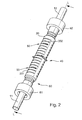
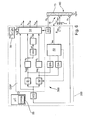
- the inline measuring device 1 for example provided in the form of a Coriolis mass flow, density and/or viscosity meter, includes therefor a vibratory transducer 10 flowed-through by the medium to be measured, an example of an embodiment and developments being shown in Figs. 2 to 6 , together with a measuring device electronics 500, as illustrated schematically in Figs. 2 and 7 , electrically coupled with the vibratory-type transducer. Further, the measuring device electronics 500 may, additionally, so designed that it can, during operation of the inline measuring device 1, exchange measurement and/or operational data with a measured value processing unit superordinated, i.e.
- the measuring device electronics is designed such that it can be supplied from an external energy supply, for example also over the aforementioned field bus system.
- the vibratory measuring device is provided for coupling to a field bus or some other communication system
- the, especially programmable, measuring device electronics 500 is equipped with a corresponding communications interface for a communication of data, e.g. for the transmission of the measurement data to the already mentioned, programmable logic controller or to a superordinated process control system.
- an electronics housing 200 is additionally provided, especially one mounted externally directly onto the vibratory transducer 10, but even one possibly set apart from such.
- the inline measuring device includes a vibratory transducer, which is flowed-through by the medium to be measured, and which serves for producing, in a through-flowing medium, mechanical reaction forces, especially Coriolis forces, dependent on the mass flow rate, inertial forces dependent on the density of the medium and/or frictional forces dependent on the viscosity of the medium, forces which react measurably, i.e. capable of being detected by sensor, on the vibratory transducer. Derived from these reaction forces characterizing the medium, e.g. the mass flow rate, the density and/or the viscosity of the medium can be measured in manner known to those skilled in the art. In Figs.
- an example of an embodiment of an electrophysical transducer arrangement, serving as a vibratory transducer 10, is schematically illustrated.
- the mechanical construction and manner of functioning of such a transducer arrangement is known per se to those skilled in the art and is also described in detail in US-B 6,691,583 , WO-A 03/095949 or WO-A 03/095950 .
- the vibratory transducer includes at least one measuring tube 10 of predeterminable measuring tube diameter.
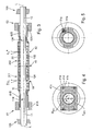
- the at least one measuring tube 10 may be a curved tube or, as shown in Fig. 3 and 4 , an essentially straight tube.
- the tube 10 is caused to vibrate, at least at times, and is repeatedly elastically deformed thereby.
- Elastic deformation of the measuring tube lumen means here, that a spatial form and/or a spatial position of the measuring tube lumen is changed within an elastic range of the measuring tube 10 in predeterminable manner cyclically, especially periodically; compare, in this connection, also US-A 4,801,897 , US-A 5,648,616 , US-A 5,796,011 , US-A 6,006,609 , US-B 6,691,583 , WO-A 03/095949 and/or WO-A 03/095950 .
- the vibratory transducer serving for implementation of the invention can, as well, be selected from a multiplicity of vibratory transducers known in the state of the art.
- the vibratory transducer having two parallel, straight measuring tubes flowed-through by the medium to be measured, such as are described in detail also in US-A 5,602,345 .
- the vibratory transducer 1 additionally has a vibratory transducer housing 100 surrounding the measuring tube 10, as well as surrounding possible other components of the vibratory transducer (see also further below).
- Housing 100 acts to protect tube 10 and other components from damaging environmental influences and/or to damp possible outwardly-directed sound emissions of the vibratory transducer.
- the vibratory transducer housing 100 also serves as a mounting platform for an electronics housing 200 housing the measuring device electronics 500.
- the vibratory transducer housing 100 is provided with a neck-like transition piece, on which the electronics housing 200 is appropriately fixed; compare Fig. 1 .
- the tube-shaped transducer housing 100 shown here extending coaxially with the measuring tube, other suitable housing forms can, of course, be used, such as e.g. box-shaped structures.
- the measuring tube 10 is oscillatably suspended in the preferably rigid, especially bending- and twisting-stiff, transducer housing 100.
- the measuring tube is inserted into the course of the pipeline and connected to the pipeline via an inlet tube piece 11 opening into the inlet end 11# and an outlet tube piece 12 opening into the outlet end 12#, such that the measuring tube communicates in the usual manner at inlet and outlet ends with the pipeline introducing, respectively extracting, the medium to be measured.
- Measuring tube 10, inlet tube piece 11 and outlet tube piece 12 are aligned with one another and with the above-mentioned measuring tube longitudinal axis L as exactly as possible and are, advantageously, provided as one piece, so that e.g.
- measuring tube 10 and tube pieces 11, 12 can, however, also be manufactured by means of separate, subsequently joined, e.g. welded, stock.
- tubular pieces 11, 12 practically every usual material for such vibratory transducers can be used, such as e.g. alloys of iron, titanium, zirconium and/or tantalum, synthetic materials, or ceramics.
- first and second flanges 13, 14 are preferably formed on the inlet tube piece 11 and the outlet tube piece 12, respectively; if required, the inlet and outlet tube pieces can, however, also be connected directly to the pipeline, e.g. by means of welding or brazing.
- the transducer housing 100 is provided, fixed to the inlet and outlet tube pieces 11, 12, for accommodating the measuring tube 10; compare, in this connection, Figs. 1 and 2 .
- the measuring tube 10 is excited in a first mode of oscillation, so called “driving mode” or “useful mode", developed as a lateral oscillation mode.
- driving mode the measuring tube 10 executes, at least in part, oscillations, i.e. bending oscillations, laterally to an imaginary measuring tube longitudinal axis L.
- the at least one measuring tube is vibrated within a first one of a plurality of natural eigenmodes.
- the measuring tube 10 executes oscillations in a first eigenmode such that it oscillates laterally outwards at a natural bending eigenfrequency, according to a natural, first form of eigenoscillation.
- the instantaneous resonance frequency of said first natural eigenmode is usually different from an instantaneous resonance frequency of any higher order eigenmodes of the measuring tube.
- the measuring tube 10 oscillating in the first mode of oscillation, induces Coriolis forces in the medium as it flows through. These, in turn, interact with the measuring tube 10 and result, in the manner known to those skilled in the art, in an additional, sensor-detectable deformation of the measuring tube 10 coplanarly superimposed on the oscillation under the driving mode. These additional deformation correspond essentially to a form of a higher order natural, second eigenmode of the tube, the so-called "Coriolis mode".
- the instantaneous shape of the deformation of the measuring tube 10 is, in such case, especially as regards its amplitudes, also dependent on the instantaneous mass flow rate ⁇ .
- the deflection caused by the Coriolis forces having the same frequency as the deflection according to the driving mode however, the - herein symmetric - driving mode and the - here anti-symmetric - Coriolis mode are superimposed 90° out of phase.
- the at least one measuring tube conducting said mixture vibrates also in a second one of said plurality of its natural eigenmodes.
- the at least one measuring 10 is also driven, at least at times, in a torsional mode of oscillation, for producing viscosity-dependent, shear forces in the flowing medium.
- the measuring tube In this torsional mode of oscillation, the measuring tube is excited to torsional oscillations about an axis of torsional oscillation extending essentially parallel to, or coinciding with, the longitudinal axis L of the measuring tube. Essentially, this excitement is such that the measuring tube 10 is twisted about its longitudinal axis L in a form of natural, torsional oscillation; compare, in this connection, e.g. also US-A 4,524,610 , US-A 5,253,533 , US-A 6,006,609 or EP-A 1 158 289 .
- the exciting of said torsional oscillations can, in such case, occur either in alternation with the first useful mode of oscillation and separated therefrom, in a second useful mode of oscillation, or, at least in the case of mutually distinguishable oscillation frequencies, also simultaneously with the lateral oscillations in the first useful mode of oscillation.
- the vibratory transducer works, at least at times, in a dual-mode of operation, in which the at least one measuring tube 10 is caused to vibrate alternatingly in at least two oscillation modes essentially independent of one another, namely in the lateral oscillation mode and in the torsional oscillation mode.
- the measuring tube 10 for producing the mass flow rate-dependent Coriolis forces in the flowing medium, is excited, at least at times, with a lateral oscillation frequency, which corresponds as exactly as possible to a lowest natural bending eigenfrequency of the measuring tube 10, so that, thus, the laterally oscillating measuring tube 10, without fluid flowing through it, is essentially symmetrically bowed outwards with respect to a middle axis perpendicular to the longitudinal axis L of the measuring tube and, in doing so, exhibits a single oscillation antinode.
- a lateral oscillation frequency which corresponds as exactly as possible to a lowest natural bending eigenfrequency of the measuring tube 10
- This lowest bending eigenfrequency can be, for example, in the case of a stainless steel tube serving as the measuring tube 10, of nominal diameter 20 mm, wall thickness about 1.2 mm and length about 350 mm, with the usual appendages, about 850 Hz to 900 Hz.
- the measuring tube 10 may excited, especially simultaneously to the lateral oscillations in the first useful mode, with a torsional oscillation frequency f excT , which corresponds as exactly as possible to a natural torsional eigenfrequency of the measuring tube.
- a lowest torsional eigenfrequency can, for example, lie in the case of a straight measuring tube about in the range of twice the lowest bending eigenfrequency.
- a counteroscillator 20 is, therefore, provided in the vibratory transducer fixed to the inlet and outlet ends of the measuring tube 10.
- the counteroscillator 20 is, as shown schematically in Fig. 2 , preferably embodied as one piece.
- the counteroscillator 20 can be composed of multiple parts, as shown e.g. also in US-A 5,969,265 , EP-A 317 340 or WO-A 00/14485 , or it can be implemented by means of two separate counteroscillator portions fixed to the inlet and outlet ends of the measuring tube 10.
- the counteroscillator 20 serves, among other things, to balance the vibratory transducer dynamically for at least one, predetermined density value of the medium, for example a density value most frequently to be expected, or also a critical density value, to such an extent that transverse forces and/or bending moments possibly produced in the vibrating measuring tube 10 are largely compensated; compare, in this connection, also US-B 6,691,583 .
- the counteroscillator 20 serves for the above-described case, where the measuring tube 10 is also excited during operation to torsional oscillations, additionally to produce counter torsional moments largely compensating such torsional moments as are produced by the single measuring tube 10 preferably twisting about its longitudinal axis L, thus holding the environment of the vibratory transducer, especially, however, the connected pipeline, largely free of dynamic torsional moments.
- the counteroscillator 20 can, as shown schematically in Figs. 2 and 3 , be embodied in tube shape and can be connected, for example, to the inlet end 11# and the outlet end 12# of the measuring tube 10 in such a manner that it is, as shown in Fig. 3 , arranged essentially coaxially with the measuring tube 10.
- the counteroscillator 20 can be made of practically any of the materials also used for the measuring tube 10, thus, for example, stainless steel, titanium alloys, etc.
- the counteroscillator 20 which is, especially in comparison to the measuring tube 10, somewhat less torsionally and/or bendingly elastic, is likewise caused to oscillate during operation and, indeed, with essentially the same frequency as the measuring tube 10, but out of phase therewith, especially with opposite phase. To this end, the counteroscillator 20 is caused to oscillate with at least one of its torsional eigenfrequencies tuned as accurately as possible to those torsional oscillation frequencies, with which the measuring tube is predominantly caused to oscillate during operation.
- the counteroscillator 20 is adjusted also in at least one of its bending eigenfrequencies to at least one bending oscillation frequency with which the measuring tube 10, especially in the first mode, is caused to oscillate, and the counteroscillator 20 is excited during operation of the vibratory transducer also to lateral oscillations, especially bending oscillations, which are developed essentially coplanarly with lateral oscillations of the measuring tube 10, especially the bending oscillations of the useful mode.
- the counteroscillator 20 has, for this purpose, grooves 201, 202, which make possible an exact adjustment of its torsional eigenfrequencies, especially a sinking of the torsional eigenfrequencies through a sinking of a torsional stiffness of the counteroscillator 20.
- the grooves 201, 202 are shown in Fig. 2 or Fig. 3 essentially uniformly distributed in the direction of the longitudinal axis L, they can, if required, also be arranged, without more, distributed non-uniformly in the direction of the longitudinal axis L.
- the mass distribution of the counteroscillator can, as likewise shown schematically in Fig. 3 , also be corrected by means of corresponding mass balancing bodies 101, 102 fixed to the measuring tube 10.
- These mass balancing bodies 101, 102 can be e.g. metal rings pushed onto the measuring tube 10, or small metal plates fixed thereto.
- the vibratory transducer additionally includes an exciter arrangement 40, especially an electrodynamic one, coupled to the measuring tube and adapted to impart motion to said at least one measuring tube.
- the exciter arrangement 40 serves for converting an electrical exciter power P exc fed from the measuring device electronics, e.g. having a regulated excitation current i exc and/or a regulated voltage, into an e.g. pulse-shaped, or harmonic, exciter moment M exc and/or an exciter force F exc acting on, and elastically deforming, the measuring tube 10.
- the exciter power P exc is tuned as exactly as possible such that predominantly the oscillations of the measuring tube 10 in the useful mode are maintained, and, indeed, as accurately as possible to an instantaneous eigenfrequency of the measuring tube containing the medium flowing therethrough.
- the exciter force F exc can, in this case, as is shown schematically in Fig. 4 , each be developed bidirectionally or, however, also unidirectionally, and can be adjusted in the manner known to those skilled in the art, e.g. by means of a current and/or voltage regulating circuit as regards their amplitude and e.g.
- the exciter arrangement 40 can include, as usual in the case of such vibratory measurement-pickups, for instance a plunger coil arrangement having a cylindrical exciter coil attached to the counteroscillator 20 or to the inside of the transducer housing 100. In operation, the exciter coil has a corresponding excitation current i exc flowing through it. Additionally included in the exciter arrangement 40 is a permanently magnetic armature extending at least partially into the exciter coil and fixed to the measuring tube 10. Furthermore, the exciter arrangement 40 can also be realized by means of a plurality of plunger coils, or also by means of electromagnets, such as e.g. shown in US-A 4,524,610 or WO-A 03/095950 .
- the vibratory transducer additionally includes a sensor arrangement 50, which produces, as a representation of vibrations of the measuring tube 10 at least one oscillation measurement signal. Therefore, sensor arrangement includes at least a first oscillation sensor 51, which reacts to vibrations of the measuring tube and which delivers, a first oscillation measurement signal s 1 .
- the oscillation sensor 51 can be formed by means of a permanently magnetic armature, which is fixed to the measuring tube 10 and interacts with a sensor coil mounted on the counteroscillator 20 or the transducer housing. To serve as the oscillation sensor 51, especially such sensors are suited, which detect a velocity of the deflections of the measuring tube 10, based on the electrodynamic principle.
- the sensor arrangement 60 includes, additionally, a second oscillation sensor 52, especially one identical to the first oscillation sensor 51.
- the second sensor 52 provides a second oscillation measurement signal s 2 likewise representing vibrations of the measuring tube 10.
- the two oscillation sensors 51, 52 are in this embodiment so arranged in the vibratory transducer 10, separated from one another along the length of the measuring tube 10, especially at equal distances from the halfway point of the measuring tube 10, that the sensor arrangement 50 locally registers both inlet-end and outlet-end vibrations of the measuring tube 10 and converts them into the corresponding oscillation measurement signals s 1 , s 2 .
- the two oscillation measurement signals s 1 , s 2 which usually each exhibit a signal frequency corresponding to an instantaneous oscillation frequency of the measuring tube 10, are, as shown in Fig. 2 , fed to the measuring device electronics 500, where they are preprocessed, especially digitized, and then suitably evaluated by means of corresponding components.
- the at least one oscillation measurement signal may include at least a second measurement signal component corresponding to said second one of said plurality of natural eigenmodes of said at least one measuring tube conducting said mixture.
- the exciter arrangement 40 is, as, in fact, shown in Figs. 2 and 3 , so constructed and arranged in the vibratory transducer, that it acts, during operation, simultaneously, especially differentially, on the measuring tube 10 and on the counteroscillator 20.
- the exciter arrangement 40 is, as, in fact, shown in Fig. 2 , advantageously so constructed and so arranged in the vibratory transducer, that it acts, during operation, simultaneously, especially differentially, on the measuring tube 10 and on the counteroscillator 20.
- Fig. 2 advantageously so constructed and so arranged in the vibratory transducer, that it acts, during operation, simultaneously, especially differentially, on the measuring tube 10 and on the counteroscillator 20.
- the exciter arrangement 40 has, for such purpose, at least one first exciter coil 41 a, through which the excitation current, or an excitation current component, flows at least at times during operation.
- the exciter coil 41 a is fixed to a lever 41 c connected to the measuring tube 10 and acts differentially on the measuring tube 10 and the counteroscillator 20 via this lever and an armature 41 b fixed externally to the counteroscillator 20.
- This arrangement has, among others, the advantage that, on the one hand, the counteroscillator 20, and thus also the transducer housing 20, is kept small in cross section and, in spite of this, the exciter coil 41 a is easily accessible, especially also during assembly.
- a further advantage of this embodiment of the exciter arrangement 40 is that possible used coil cups 41 d, which especially at nominal diameters of over 80 mm, have weights which can no longer be ignored, are fixable on the counteroscillator 20 and, consequently, have practically no influence on the eigenfrequencies of the measuring tube 10. It is to be noted here, however, that, in case required, the exciter coil 41 a can also be held by the counteroscillator 20 and the armature 41 b, then, by the measuring tube 10.
- the oscillation sensors 51, 52 can be so designed and arranged in the vibratory transducer that the vibrations of the measuring tube 10 and the counteroscillator 20 are registered differentially by them.
- the sensor arrangement 50 includes a sensor coil 51 a fixed to the measuring tube 10, here outside of all principal axes of inertia of the sensor arrangement 50.
- the sensor coil 51 a is arranged as close as possible to an armature 51 b fixed to the counteroscillator 20 and magnetically so coupled with such, that a changing measurement voltage is induced in the sensor coil, influenced by rotary and/or lateral, relative motions between measuring tube 10 and counteroscillator 20 in changing their relative position and/or their relative separation.
- both the above-mentioned torsional oscillations and the excited bending oscillations can, advantageously, be registered simultaneously.
- the sensor coil 51 a therefor can, however, also be fixed to the counteroscillator 20 and the armature 51 b coupled therewith can, correspondingly, then be fixed to the measuring tube 10.
- measuring tube 10, counteroscillator 20 and the sensor and exciter arrangements 40, 50 secured thereto are so matched to one another with respect to their mass distribution, that the resulting inner part of the vibratory transducer, suspended by means of the inlet and outlet tube pieces 11, 12, has a center of mass MS lying at least inside of the measuring tube 10, and preferably as close as possible to the longitudinal axis L of the measuring tube.
- the inner part is advantageously so constructed that it has a first principal axis of inertia T 1 aligned with the inlet tube piece 11 and the outlet tube piece 12 and lying at least sectionally within the measuring tube 10.
- the two oscillation forms assumed in operation by the measuring tube 10 and largely compensated by the counteroscillator 20, namely the torsional oscillations and the bending oscillations of the measuring tube 10, are highly mechanically decoupled from one another; compare, in this connection, also WO-A 03/095950 .
- the two forms of oscillation, thus lateral oscillations and/or torsional oscillations are advantageously, without more, excited separately from one another.
- Both the displacement of the center of mass MS and also the first principal axis of inertia T 1 toward the longitudinal axis of the measuring tube can, for example, be considerably simplified by having the inner part, thus measuring tube 10, counteroscillator 20 and the sensor and exciter arrangements 50, 40 secured thereto, so constructed and arranged with respect to one another, that a mass distribution of the inner part along the length of the measuring tube longitudinal axis L is essentially symmetrical, at least, however, invariant relative to an imaginary rotation about the longitudinal axis L of the measuring tube by 180° (c2-symmetry).
- the counteroscillator 20 - here tubularly, especially also largely axially symmetrically, embodied - is arranged essentially coaxially with the measuring tube 10, whereby the reaching of a symmetrical distribution of mass in the inner part is significantly simplified, and, consequently, also the center of mass MS is displaced in simple manner close to the longitudinal axis L of the measuring tube.
- the sensor and exciter arrangements 50, 40 in the example of an embodiment presented here are so constructed and arranged relative to one another on the measuring tube 10 and, where appropriate, on the counteroscillator 20, that a mass moment of inertia produced by them is developed as concentrically as possible to the longitudinal axis L of the measuring tube or at least is kept as small as possible.
- the exciter arrangement 40 is, for the purpose of the separated exciting of torsional and/or bending oscillations of the measuring tube 10, so constructed and so fixed to the measuring tube 10 and to the counteroscillator 20, that a force producing the bending oscillations acts on the measuring tube 10 in the direction of an imaginary line of force extending outside of a second principal axis of inertia T 2 perpendicular to the first principal axis of inertia T 1 , or intersecting the second principal axis of inertia in, at most, one point.
- the inner part is so embodied that the second principal axis of inertia T 2 is essentially the above-mentioned middle axis.
- the exciter arrangement 40 has, for this purpose, at least one first exciter coil 41a, through which the excitation current or an excitation current component flows at least at times during operation.
- Exciter coil 41a is fixed to a lever 41c connected with the measuring tube 10 and via this lever and an armature 41b fixed externally to the counteroscillator 20, acts differentially on the measuring tube 10 and the counteroscillator 20.
- This arrangement has, among other things, also the advantage that, on the one hand, the counteroscillator 20 and, consequently, also the transducer housing 100 are kept small in cross section and, in spite of this, the exciter coil 41a is easily accessible, especially also during assembly.
- a further advantage of this embodiment of the exciter arrangement 40 is that possibly used coil cups 41d, which especially at nominal diameters of over 80 mm have weights that no longer can be neglected, can likewise be fixed to the counteroscillator 20 and, consequently, have practically no effect on the resonance frequencies of the measuring tube. It should be noted here that, when required, the exciter coil 41 a can also be mounted to the counteroscillator 20 and then the armature 41 b is held by the measuring tube 10.
- the exciter arrangement 40 has at least one, second exciter coil 42a arranged along a diameter of the measuring tube 10 and coupled with the measuring tube 10 and the counteroscillator 20 in the same way as the exciter coil 41 a.
- the exciter arrangement has two further exciter coils 43a, 44a, thus a total of four, at least arranged symmetrically with respect to the second principal axis of inertia T 2 . All coils are mounted in the vibratory transducer in the above-described manner.
- the force acting on the measuring tube 10 outside of the second principal axis of inertia T 2 can be produced by means of such two, or four, coil arrangements in simple manner e.g. by having one of the exciter coils, e.g. the exciter coil 41 a, exhibit another inductance than the respective others, or by causing to flow through one of the exciter coils, e.g. the exciter coil 41 a, during operation, an excitation current component that is different from a respective excitation current component of the respectively other exciter coils.
- the sensor arrangement 50 includes, as shown schematically in Fig. 5 , a sensor coil 51 a arranged outside of the second principal axis of inertia T 2 and fixed to measuring tube 10.
- the sensor coil 51 a is arranged as near as possible to an armature 51 b fixed to the counteroscillator 20 and is magnetically coupled therewith such that a changing measurement voltage is induced in the sensor coil, influenced by rotary and/or lateral relative motions between measuring tube 10 and counteroscillator 20 as they change their relative positions and/or their relative separations.
- both the above-described torsional oscillations and the bending oscillations, excited where appropriate, can be registered in advantageous manner simultaneously.
- the sensor coil 51a therefor can, instead, be fixed to the counteroscillator 20 and, in corresponding manner, the armature 51 b coupled therewith can be fixed to the measuring tube 10.
- the exciter arrangement 40 and the sensor arrangement 50 can also have, in the manner known to those skilled in the art, essentially the same mechanical structure; consequently, the above-described embodiments of the mechanical structure of the exciter arrangement 40 can essentially also be transferred to the mechanical structure of the sensor arrangement 50, and vice versa.
- the exciter arrangement 40 is fed with an excitation signal.
- the excitation signal may include at least a first excitation signal component corresponding to said first one of natural eigenmodes of said at least one measuring tube conducting said mixture.
- the exciter arrangement 40 may, as already mentioned, fed with a likewise oscillating excitation current i exc , especially a multifrequency current, of adjustable amplitude and adjustable exciter frequency f exc such that this current flows through the exciter coils 26, 36 during operation and the magnetic fields required for moving the armatures 27, 37 are produced in corresponding manner.
- the excitation current i exc can be e.g. harmonically multifrequent or even rectangular.
- the lateral oscillation exciter frequency f excL of a lateral current component i excL of the excitation current i exc required for maintaining the lateral oscillations of the measuring tube 10 can advantageously be so chosen and adjusted in the case of the vibratory transducer shown in the example of an embodiment that the laterally oscillating measuring tube 10 oscillates essentially in a bending oscillation base mode having a single oscillation antinode.
- a torsional oscillation frequency f excT of a torsional current component i excT of the excitation current i exc required for maintaining the torsional oscillations of the measuring tube 10 can advantageously be so chosen and adjusted in the case of the vibratory transducer shown in the example of an embodiment that the torsionally oscillating measuring tube 10 oscillates essentially in a torsional oscillation base mode having a single oscillation antinode.
- the two mentioned current components i excL and i excT can, depending on the type of operation selected, be fed into the exciter arrangement 40 intermittently, thus instantaneously each acting as the excitation current i exc , or also simultaneously, thus supplementing one another to form the effective excitation current i exc .
- the excitation signal may include at least a first and a second excitation signal component corresponding to a first one and a second one, repectively, of a plurality of natural eigenmodes of said at least one measuring tube conducting said mixture.
- a separation of the individual oscillation modes can occur both in the exciter signals and also in the sensor signals, by means of the vibratory transducer in simple and advantageous manner, even in the case of simultaneously excited torsional and bending oscillations, e.g. based on a signal filtering or a frequency analysis. Otherwise, an alternating exciting of the lateral and torsional oscillations recommends itself.
- the measuring device electronics includes a corresponding driver circuit 53, which is controlled by a lateral oscillation frequency adjustment signal y FML representing the desired lateral oscillation exciter frequency f excL and by a lateral oscillation amplitude adjustment signal y AML representing the desired lateral oscillation amplitude of the excitation current i exc and/or the lateral current component i excL , as well as, at least at times, by a torsional oscillation frequency adjustment signal y FMT representing the torsional oscillation exciter frequency f excT and by a torsional oscillation amplitude adjustment signal y AMT representing the desired torsional oscillation amplitude of the excitation current i exc and/or the torsional current component i excT .
- a lateral oscillation frequency adjustment signal y FML representing the desired lateral oscillation exciter frequency f excL
- a lateral oscillation amplitude adjustment signal y AML representing the desired lateral oscillation amplitude of the excitation current i exc and/or the
- the driver circuit 53 can be realized e.g. by means of a voltage-controlled oscillator or a downstream voltage-to-current converter; instead of an analog oscillator, however, also a numerically controlled, digital oscillator can be used to set the instantaneous excitation current i exc or the components i excL , i excT of the excitation current.
- An amplitude control circuit 51 integrated into the measuring device electronics 500 can serve for producing the lateral amplitude adjustment signal y AML and/or the torsional oscillation amplitude adjustment signal y AMT .
- the amplitude control circuit 51 actualizes the amplitude adjustment signals Y AML , y AMT on the basis of instantaneous amplitudes of at least one of the two oscillation measurement signals s 1 , s 2 measured at the instantaneous lateral oscillation frequency and/or the instantaneous torsional oscillation frequency, as well as on the basis of corresponding, constant or variable amplitude reference values for the lateral and torsional oscillations, respectively W B , W T ; as appropriate, also instantaneous amplitudes of the excitation current i exc can be referenced for generating the lateral oscillation amplitude adjustment signal y AML and/or the torsional oscillation amplitude adjustment signal y AMT ; compare Fig.
- amplitude control circuits Construction and manner of operation of such amplitude control circuits are likewise known to those skilled in the art.
- Their amplitude control circuit is preferably so constructed that the lateral oscillations of the measuring tube 10 are controlled to a constant amplitude, thus an amplitude also independent of the density ⁇ .
- the frequency control circuit 52 and the driver circuit 53 can be constructed e.g. as phase-locked loops, which are used in the manner known to those skilled in the art for adjusting the lateral oscillation frequency adjusting signal y FML and/or the torsional oscillation frequency adjusting signal y FMT continuously for the instantaneous eigenfrequencies of the measuring tube 10 on the basis of a phase difference measured between at least one of the oscillation measurement signals s 1 , s 2 and the excitation current i exc to be adjusted, respectively the instantaneously measured excitation current i exc .
- phase-locked loops for the driving of measuring tubes at one of their mechanical eigenfrequencies is described in detail in e.g.
- the amplitude control circuit 51 and the frequency control circuit 52 are, as shown schematically in Fig. 6 , realized by means of a digital signal processor DSP provided in the measuring device electronics 500 and by means of program code correspondingly implemented in such and running therein.
- the program codes can be stored persistently or even permanently e.g. in a non-volatile memory EEPROM of a microcomputer 55 controlling and/or monitoring the signal processor and loaded upon startup of the signal processor DSP into a volatile data memory RAM of the measuring device electronics 500, e.g. RAM integrated in the signal processor DSP.
- Signal processors suited for such applications are e.g. those of type TMS320VC33 available from the firm Texas Instruments Inc..
- the oscillation measurement signals s 1 , s 2 need to be converted by means of corresponding analog-to-digital converters A/D into corresponding digital signals for a processing in the signal processor DSP; compare, in this connection, EP-A 866,319 for example.
- adjustment signals output from the signal processor such as e.g. the amplitude adjusting signals y AML , Y AMT , or the frequency adjusting signals y FML , y FMT , can be, in corresponding manner, converted from digital to analog.
- the, if appropriate, first suitably conditioned, oscillation measurement signals s 1 , s 2 are additionally sent to a measurement circuit 21 of the measuring device electronics for producing the at least one measured value X x on the basis of at least one of the oscillation measurement signals s 1 , s 2 and/or on the basis of the excitation current i exc .
- the measurement circuit 21 is constructed, at least in part, as a flow rate calculator and the measurement circuit serves for determining, in the manner known per se to those skilled in the art, from a phase difference detected between the oscillation measurement signals s 1 , s 2 generated in the case of a measuring tube 10 oscillating laterally at least in part, a measured value X x serving here as a mass flow rate measured value and representing, as accurately as possible, the mass flow rate to be measured.
- the measurement circuit 21 can be any, especially digital, measuring circuit already used in conventional Coriolis mass flow measuring devices for determining the mass flow rate on the basis of the oscillation measurement signals s 1 , s 2 ; compare, in this connection, especially the initially mentioned WO-A 02/37063 , WO-A 99/39164 , US-A 5,648,616 , US-A 5,069,074 .
- Other measuring circuits known to those skilled in the art to be suitable for Coriolis mass flow measuring devices can be used, i.e. measuring circuits which measure, and correspondingly evaluate, phase and/or time differences between oscillation measurement signals of the described kind.
- the measurement circuit 21 can also serve to utilize an oscillation frequency of the at least one measuring tube 11, as measured, for example, on the basis of at least one of the oscillation measurement signals s 1 , s 2 , for generating a measured value X x usable as a density measured value instantaneously representing a density ⁇ to be measured for the medium or a phase of the medium.
- the measurement circuit can also be used to determine a measured value X x usable as a viscosity measured value and instantaneously representing a viscosity of the medium.
- the measurement circuit may derive such measured value from the excitation current i exc , which, it is known, can serve also as a measure for an apparent viscosity or also a viscosity-density product; compare, in this connection, also US-A 4,524,610 or WO-A 95 16 897 .
- the inline measuring device can determine the separate measured values X x , i.e. mass flow value X m , a density value X ⁇ , and a viscosity value X ⁇ , respectively, for the various measured quantities x both in a common measuring cycle, thus with equal updating rates, as well as with different updating rates.
- a very accurate measurement of the usually significantly varying mass flow rate requires usually a very high updating rate, while the comparatively less variable viscosity, ⁇ , of the medium can, where appropriate, be updated at larger separations in time.
- the measurement circuit 21 can, furthermore, also be implemented by means of the signal processor DSP.
- inline measuring devices with a vibratory transducer are widely used in industry for mass flow and density measurement of single-phase liquids or gases due to the high accuracy and flexibility of such devices.
- inhomogeneities and/or the formation of first and second phases in the flowing medium for example gas bubbles and/or solid particles entrained in liquids, can lead to the result that a measured value determined in conventional manner assuming a single-phase and/or homogeneous medium will not match with sufficient accuracy the actual value of the quantity x whose measurement is desired, for example the mass flow rate m, i.e. the measured value must be appropriately corrected.
- the determination of the initial measured or apparent value X' x which, for practical purposes, corresponds to the measured value generated in conventional manner, presents no difficulties for those skilled in the art, so that the initial measured value X' x can be taken as a given for the further explanation of the invention.
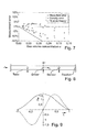
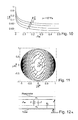
- Fig. 7 shows exemplarily a typical behaviour of a conventional Coriolis flowmeter under multi phase condition.
- MRM moving resonator model
- the Coriolis working principle under ideal conditions is our starting point for conceptualizing this moving resonator.
- this resonator is implemented into the flow meter which allows calculation of density and mass flow errors during on-line operation.
- the error compensation based on the "bubble theory” may be included or integrated in this computation.
- a t and A define the areas of cross-section and ⁇ t and ⁇ are the densities of the tube and the fluid, respectively.
- the first term represents the bending force layer of the tube
- the second term gives the ordinary inertial force layers of tube and fluid
- the third term on the left hand side gives the Coriolis force, where v is the velocity of the fluid.
- the first two eigenmodes we are interested exemplarily in the first two eigenmodes.
- the first one we have denote with the subscript D, which represents the so called driving mode (see also above).
- the second one we have selected the Coriolis mode, hereinafter denoted with the subscript C .
- the oscillation form of the Coriolis mode does correspond with the deflection caused by Coriolis forces within the flowing mixture under the selected driving mode.
- Fig. 9 the symmetric driving mode and the antisymmetric Coriolis mode for a single straight measuring tube are shown.
- the real driving frequency may about 286.7 Hz for air and 218.6 Hz for water.
- the Coriolis mode A C is excited by the driving mode A D via the mass flow.
- the modal amplitudes A D , A C can be derived from the sensor signals, for instance in conventional way by building sum and difference followed by synchronous demodulation.
- Sound velocities in the gas, fluid and mixture are denoted by c g , c l and c. Furthermore, ⁇ l , ⁇ and ⁇ are the density of liquid, the density of mixture and the adiabatic constant, respectively.
- the parameters, which has to be taken into account, are the gas volume concentration ⁇ , also named void fraction, and the static pressure p .
- Fig. 10 shows the dependency of sound velocity on gas concentration for different pressures when the liquid phase is water and the gas phase is air. According to Eq. (16), the sound velocity in the mixture decreases dramatically even with a small gas concentration. If for example 1.5 % air at 10 5 Pa is injected, the sound velocity of water decreases from 1460 m/s to 95 m/s. This can be explained as a small amount of weak gas decreases the stiffness of the mixture greatly. The reduced sound velocity, in turn, decreases the resonance frequency of the mixture in the tube, which will be discussed below.
- the resonance frequency may fall down from 8557 Hz for pure water to 555 Hz for the mixture.
- the corresponding velocity field of the primary eigenform based on the Bessel function is shown in Fig. 11 .
- the maximum velocity of the x-component appears in the central region.
- the resonance frequency of a single-phase flow resonator is usually much higher than the driving frequencies of Coriolis flow meters, the corresponding resonator effect is negligible compared with the typical magnitude of multiphase related errors. Contrary, because gas entrained in liquid reduces the resonance frequency significantly, such that the sound speed in a mixture is often lower than that in either of its individual phases and/or components, in this case, the resonator effect plays a non- negligible role. When a vibrating measuring tube drives such a mixture, the Coriolis flowmeter "feels" a different density from the real one, and by extension, a different mass flow rate.
- the effective mass m 0 of the resonator is the effective mass m 0 of the resonator.
- the first eigenmode of the resonator could assume to be the dominant mode, here we use only the modal mass layer of said first eigenmode to model an associated single-mass resonator with effective mass m 0 , while all masses of higher modes are collected in the inactive modal mass layer m ' which sticks to the tube wall. Consequently, the fluid resonator could be seen as a substantially single-degree forced excitation system [ L.
- the measuring tube represents the oscillating boundary of the fluid domain which forces vibrations in the mixture. Due to the interaction between the moving resonator and the vibrating tube, a reaction force layer F responds to the tube wall motion.
- the curves in Fig. 13 are based on the equations above and they are related to the driving mode.
- the solid one being the track of the inactive mass m ' sticking to the tube and the dashed one being the effective resonator mass m 0 , moving along the conduit. It can be seen that on the way through the tube an amplitude difference and phase shift occurs.
- Eq. (4), (5), (6), (9), (25), and (28) now we can calculate the reaction force F .
- the time domain is transferred back to the space domain by using the inverse relationship to Eq. (28).
- t ⁇ + 1 ⁇ l 2 ⁇ v
- t l ⁇ ⁇ + 1 2 ⁇ ⁇
- t l ⁇ ⁇ + 1 2 ⁇ ⁇
- Each modal component F D , F C of the force layer F is a complex and asymmetric function.
- these forces are decomposed in their real components ( F D , F C ⁇ and imaginary components ⁇ F D , F C ⁇ as well as symmetric and antisymmetric components.
- (33) represents the apparent density reading from the meter and f ⁇ i is the disturbed frequency currently measured.
- the subscript i indicates the respective mode, and may, for example, correspond to the numbers of antinodes of the oscillation form of the tube. Note the term “disturbed” here means the change due to the two-or multi phase flow.
- E ⁇ between true or reference density, ⁇ , and apparent density, ⁇ , in two-phase conditions may derived based on the following equation:
- the first term represents the bending force of the tube, where E t is Young's modulus of the tube wall, I t is the second moment of tube cross-section area, x is the displacement of the tube in vertical direction and z is the horizontal coordinate.
- the second term represents the ordinary inertia force of the tube, where A t is the area of tube cross-section and ⁇ t is density of the tube.
- the resonance frequencies f ⁇ Ai for the pure or reference gas, i.e. air, and f ⁇ wi for the pure or reference liquid, i.e. water may be needed.
- the values for such resonance "pure" frequencies f ⁇ Ai , f ⁇ wi which can be easily obtained by calibration, are used to determine the two coefficients c 0i , c 1i on the RHS of Eq. (43), respectively, for the corresponding mode, respectively.
- the concentration ⁇ i.e.
- liquid phase density ⁇ L may be inputted manually on site or from a remote control room, based on knowledge of the medium to be measured, or may be transmitted from an external density meter, for example via field bus, to the measuring device electronics during operation.
- density value ⁇ L can also be determined initially for the fluid directly by means of the measuring device electronics, especially in case the medium can assumed as to be a single phase fluid or, medium can assumed as to be largely homogeneous.
- ⁇ L may be determined using a density measured value X ⁇ ,0 likewise stored in the measuring device electronics, with the stored density measured value X ⁇ ,0 representing a density of the medium previous measured during operation, i. e. if the medium was actually homogeneous or the measured medium could assumed to be homogeneous.
- the resonance frequencies of the measurement tube depends also on the inherent properties of the tube such as geometry and material, and the density of the medium inside.
- the density refers to the apparent density, which is usually different from the bulk density of the mixture.
- the at least one measuring tube measurement tube is to be caused, however, to vibrate also in said actual second order eigenmode (f 2 -mode), i.e. the Coriolis like mode or a higher mode, and said second eigenmode of the tube has to be considered to obtain the complement for solving the problem.
- the second order eigenmode of a single straight tube has a higher frequency than the first order eigenmode (f 1 -mode), usually used for the driving mode.
- the resonator that simulates the two-phase mixture shows a different behavior from the f 1 -mode, usually having more significant effect because in most cases the driving frequency is closer to the resonance frequency f 0 of the resonator.
- the second mode of the measurement tube may actively excite at least intermittently, and the resulting vibrations of the tube may analyze.
- the resonator can really driven by the f 2 -mode frequency, which is provided by frequency f ⁇ 2 , and gives a corresponding reaction, which also contributes to the final resonance frequency of the f 2 -mode.
- a second method can base on on-line signal analysis.
- the signal from a sensor of the meter can be decomposed into various frequency bands, being transferred to a frequency domain.
- the resonance frequency of the f 2 -mode is obtained by an appropriate on-line spectrum analysis, i.e. based on discrete Fourier transformation and/or digital filtering.
- at least one eigenmode of the tube i.e. the f 2 - mode, may also excited at its instantaneous eigenfrequency, ifat least one of said first and second mixture phases, currently within said measuring tube, moves relative to the measuring tube and, thus, relative to the other one of said first and second mixture phases.
- the lower of the respective lines represents a widely homogeneous single-phase medium
- the upper of the respective two signal lines represents a two-phase mixture consisting of air-bubbles in water, wherein the concentration of air may have a value of about 5%.
- the excitation signal may substantially devoid of any excitation signal components, which correspond to said natural eigenmode to be stimulated only due to said relative motion of said mixture phases, and/or which would excite said natural eigenmode via said exciter arrangement.
- a first oscillation factor which represents a relation between said oscillation amplitude of said first natural eigenmode and said signal amplitude of said first excitation signal component causing said measuring tube to vibrate in said first natural eigenmode
- a second oscillation factor which represents a relation between said oscillation amplitude of said second natural eigenmode and a signal amplitude of a second excitation signal component of the excitation signal having a signal frequency corresponding with the instantaneous resonance frequency of said second natural eigenmode.
- the first oscillation factor may represent a ratio of said oscillation amplitude corresponding with the first natural eigenmode normalized to said signal amplitude of the first excitation signal component
- the second oscillation factor may represent a ratio of said oscillation amplitude corresponding with the second natural eigenmode normalized to said signal amplitude of the second excitation signal component. Consequently, in operation said excitation signal may adjusted such that said first oscillation factor is less than said second oscillation factor at least temporary.
- the signal amplitude of said second excitation signal component of the excitation signal may essentially zero.
- a signal-to-noise ratio of said second excitation signal component can be less than two.
- the excitation signal fed to said exciter arrangement, may include at least a third signal component corresponding to a third one of a plurality of natural eigenmodes of said at least one measuring tube conducting said mixture.
- This third excitation signal component may cause the measuring tube to vibrate in said third natural eigenmode with an oscillation amplitude depending at least on an amplitude of said third excitation signal component fed to the exciter arrangement.
- At least said instantaneous resonance frequency of said second natural eigenmode may significantly vary in time due to at least one of: relative motion of said first mixture and second mixture phases, changes in distribution of at least one of said first mixture and second mixture phases of the mixture within said measuring tube, and changes in a concentration of at least one of said first mixture and second mixture phases of the mixture.
- the instantaneous resonance frequency of said first natural eigenmode currently excited via exciter arrangement may also depend on said mixture currently within said measuring tube in a similar manner. Indeed, the instantaneous resonance frequencies of each of the first and second eigenmodes are significantly different from each other.
- each of said natural eigenmodes has an instantaneous resonance frequency depending on said mixture currently within said measuring tube
- each of the corresponding signal components of the oscillation measurement signal has an instantaneous signal frequency corresponding with said instantaneous resonance frequency of said second natural eigenmode. Therefore, said instantaneous signal frequencies of said first and second measurement signal components may further used for selecting said first and second measurement signal component from said oscillation measurement signal for further use in the compensation schemes as described above. Further, we have found that also an instantaneous amplitude of said oscillations within each of said first and second natural eigenmode depend on said mixture within said measuring tube. Therefore, also the signal amplitude of each of said first and second measurement signal components can be used for identifying and for selecting said measurement signal components from the oscillation measurement signal.
- any other lateral eigenmode of a single straight tube laterally vibrating has a higher resonance frequency than the first eigenmode.
- the second mode f 2 -mode
- the resonator that simulates the two-phase mixture shows a different behaviour from the f 1 -mode.
- the second order mode usually has more significant effect, because in most cases its (disturbed) resonance frequency f ⁇ 2 is closer to the resonance frequency f 0 of the fluid resonator than that of lower order eigenmodes.
- the "bubble effect" remains constant as it is widely independent of the oscillation frequency. Consequently, it is possible to solve Eq.
- Eq. (16) may further utilized.
- Eq. (47) p 0 is the atmospheric pressure and ⁇ G 0 is the compressibility of air under this atmospheric pressure.
- the process pressure p must be measured in order to know the property of the gas phase.
- Eq. (47) the equation system including Eq. (23), (41) can be solved to obtain concentration ⁇ , resonance frequency f 0 of the resonator, and liquid phase density ⁇ L , respectively.
- the quality factor Q 0 of the fluid resonator may have much less influence on the total system quality factor compared with resonator's resonance frequency f 0 , because it has a power of 3. Consequently, a small deviation between the true quality factor Q 0 and any estimated quality factor has negligible influence on the accuracy of the system quality factor Q D to be obtained and the resonator's resonance frequency f 0 to be derived therefrom. Consequently, the quality factor Q 0 could bee seen as a device parameter, which may obtained empirically based on experimental data in during calibration process of the In-Line meter. For this, we can use also a reference system with widely know homogeneous single-phase media. To improve the accuracy of the In-Line meter, during on-line operation the quality factor Q 0 may validated based on system quality factor Q D , which, for example, may derive from the current concentration ⁇ and the current driving frequency at least iteratively.
- the equation system which comprises Eqn. (33) and the first mode equation from Eq. (43), could also solved to obtain concentration ⁇ , fluid resonator's resonance frequency f 0 and liquid density ⁇ L .
- the Coriolis coupling coefficient c CD which is used here as a reference value for the mode coupling in case of homogeneous single-phase media, may calibrate previously under appropriate one-phase condition as discussed above for the quality factor Q 0 .
- Eq. (51) may further simplified as explained for Eq. (33) and (43):
- Eq. (46) and (52) consists in the fact that they do consider both, “bubble effect” and “moving resonator effect”, and can be solved during on-line operation of the inline meter.
- E m k 1 ⁇ E ⁇ , 1 + k 2 ⁇ E ⁇ , 2 , which can be seen as to be a fundamental relation for a multiphase error compensation within inline meters, i.e. a Coriolis flow meters, based on "bubble effect" and MRM as described above.
- the total system damping D D which is inversely proportional to the total system quality factor Q D , can be estimated from a ratio of the modal component of driving current I D to the respective modal components of oscillation amplitude A D of the measuring tube. Therefore, we instead of or in addition to the second mode measurement we can make use of damping measured under the driving mode to provide additional information. Consequently, based on the MRM, we can compute the measurement errors, both for density as shown in Eq. (39) and the mass flow rate as shown in Eq. (51) of multi-phase mixture in different ways. Furthermore, at least said first measurement signal component and said excitation signal may also use for generating the at least one measured value.
- both the bubble effect error and the reduced effective mass effect for the resonator must be considered in mass flow and density measurement under multiphase fluid condition. Knowing concentration ⁇ and resonator's frequency f 0 , beside the density error E ⁇ also the mass flow rate E ⁇ error, which is caused also by both, the "bubble effect" and the “resonator effect”, may calculated according to Eq. (46) and (52), respectively.
- the model of the moving resonator including the "bubble effect” may implemented numerical in a computer algebra system, for instance directly in the above mentioned microcomputer 55. Parameters and constants, which may be used for an exemplar model, are listed in Table 1.
- the MRM as described above can be utilized to compensate the measurement errors E ⁇ of Vibratory type inline meters, such as Coriolis meters. Therefore, the following error compensation setup could be used, for example: Import values could be the separately measured mixture sound speed c and measured values of the Coriolis mass flowmeter, such as driving frequency f ⁇ D , quality factor Q ⁇ D / damping D ⁇ D of the total system within the driving mode, apparent density ⁇ , and apparent mass flow .
- the measured system quality factor Q ⁇ D and the measured damping D ⁇ D are functions of driving current, especially driving mode related components of the driving current. Knowing the mixture sound speed c with Eq. (16) we can determine the fluid resonator frequency f 0 . Using Eq.
- An alternative error compensation setup may be given by: By measuring the mixture sound speed c and the pressure p with Eq. (16) the gas volume and/or liquid volume concentration ⁇ can be calculated. Alternatively this step can also be done by using an interpolated look up table, which consists of measured or calculated triples ( c , p , ⁇ ). Knowing the mixture sound speed c with Eq. (23) we can determine the resonator frequency f 0 . Using Eq. (33) the unknown parameter resonator quality factor Q 0 could be determined. Therefore, in an iterative procedure the difference between measured/calculated and true system quality factor Q ⁇ D may minimize. Finally by using Eq. (39) and Eq. (51) the true mass flow ⁇ and the true mixture density ⁇ can be determined. As a result, the error compensation algorithm gives the actual mass flow ⁇ , the actual mixture density ⁇ and the gas volume concentration ⁇ .
- concentration ⁇ and fluid resonator's resonance frequency f 0 could be determine during operation of the inline meter. Then corresponding density error E ⁇ and mass flow error E ⁇ may predict based on the MRM.
- a schematic of the experimental setup is depicted in Fig. Error! Reference source not found..
- the facility includes a reference mass flow meter before the air injection point to measure the real mass flow rate.
- the Coriolis meter used herein for generating experimental data was selected from Series "Promass F DN 50" made from Endress + Hauser Flowtec AG. As known, this Coriolis meter comprises two slightly bent tubes, and is suiteable for use pipe lines with a diameter of about 50 mm.
- the pressures before and after the Coriolis meter were also recorded to calculate concentration ⁇ and the gas volume fraction inside the Coriolis meter, respectively.
- a spectrum analyzer connected to one of the meter sensors was used. In the experiments, the flow rate was controlled to be about 15000 kg/h, and the pressure inside the meter was around 1,5 bar.
- the flowing media used herein were water-air mixtures.
- the experiments were carried out for five different gas volume fractions. Keeping the same flow conditions, we recorded the resonance frequencies f ⁇ 1 , f ⁇ 2 for the two selected modes and actual meter readings of flow rate and density respectively.
- the Coriolis meter may resonate at a frequency about 440 kHz under the f1 mode and at a frequency about 1.340 kHz under the f2 mode, see also Fig. !Syntax Error, ! and !Syntax Error, !.
- the resonance frequency of the f2 mode shifts to the left about 20 Hz, while the corresponding f1 mode frequency shifts to the right in case of the same two-phase mixture.
- the concentration ⁇ and the resonance frequency f 0 of the fluid resonator could be calculated by knowing the disturbed resonance frequencies f ⁇ 1 , f ⁇ 2 for the f1 mode and the f2 mode, respectively, then the corresponding mass flow error E ⁇ and density error E ⁇ could be estimated accordingly.
- Fig. !Syntax Error, ! shows the comparison of the measured gas volume fractions and the estimated ones according to the two-mode compensation scheme. It can be seen that the calculated values from the two-mode compensation scheme are qualitatively correct.
- Fig. !Syntax Error, !, !Syntax Error, !, and !Syntax Error, ! depict the comparisons between measured errors and the corresponding predictions by the driving mode damping compensation scheme, where the value of fluid resonator's quality factor Q 0 is taken to be 0.6.
- the predictions from the two-mode compensation scheme are also included for comparison. It can be seen that the compensation scheme based on damping can also give a good prediction to the real measure values.
- Figs. !Syntax Error, ! and !Syntax Error, ! show another experiment with the same Coriolis meter as before (PROMASS F DN50), but different flow conditions.
- the flow rates vary from 10000 to 15000 kg/h, and pressures vary from 1.8 to 2.2 bar.
- the quality factor Q 0 of the fluid resonator is still taken to be 0.6. From a comparison of these two figures with Fig. !Syntax Error, ! and !Syntax Error, ! , respectively, it can be seen that the compensation scheme based on damping shows also a good performance for the error correction.
- the general steps for realizing that two mode compensation scheme may briefly summarize as follows:
- the manufacturer provides the first mode and the second mode resonance frequencies of the at least one measurement tube for pure air and pure water respectively. During commissioning these frequencies can also be measured easily with the installed inline measuring device on-site. Based on the above frequencies, the characteristics of the resonance of the measurement tube for different loads could be determined.
- the disturbed resonance frequencies f ⁇ i of each of the selected modes i are measured when the meter encounters two-phase or multi-phase flows.
- the concentration ⁇ and the resonance frequency f 0 of the resonator are computed based on Eq. (44) and (45), respectively.
- the density error and mass flow rate error are estimated based on MRM considering both, "bubble effect” and "moving resonator effect”.
- the target measurement values of the inline measuring device i.e. mass flow rate, density, concentration etc., are outputted in corrected form.
- An advantage of the two-mode compensation scheme is that it skips these difficulties and directly evaluates the gas volume fraction and the resonance frequency by measuring the two resonance frequencies of the two modes, without additional devices such as the sound speed sensor and the pressure sensor.
- Theoretical analysis and experimental data demonstrate the validity of the two mode compensation scheme. As discussed with Fig. !Syntax Error, ! and !Syntax Error, ! , both the density error and the mass flow error are compensated to a relatively accurate range. Additionally, using at least one of the schemes the users can perceive the presence of the gas and liquid phase, respectively, and have an idea how much fraction it occupies.
- the two- or multi mode compensation scheme and the damping mode scheme may improve the accuracies of inline measuring devices, especially Coriolis mass flow meters and density meters, and may extend theirs range to applications for two-phase or multi-phase flows.
Priority Applications (1)
| Application Number | Priority Date | Filing Date | Title |
|---|---|---|---|
| EP08168408A EP2026042A1 (de) | 2005-12-27 | 2006-12-12 | In-Line-Messvorrichtungen und Verfahren zum Ausgleich von Messfehlern in In-Line-Messvorrichtungen |
Applications Claiming Priority (3)
| Application Number | Priority Date | Filing Date | Title |
|---|---|---|---|
| EP05028481 | 2005-12-27 | ||
| EP08168408A EP2026042A1 (de) | 2005-12-27 | 2006-12-12 | In-Line-Messvorrichtungen und Verfahren zum Ausgleich von Messfehlern in In-Line-Messvorrichtungen |
| EP06830551A EP1987327A1 (de) | 2005-12-27 | 2006-12-12 | Inline-messeinrichtungen und verfahren zur kompensation von messfehlern in inline-messeinrichtungen |
Related Parent Applications (1)
| Application Number | Title | Priority Date | Filing Date |
|---|---|---|---|
| EP06830551A Division EP1987327A1 (de) | 2005-12-27 | 2006-12-12 | Inline-messeinrichtungen und verfahren zur kompensation von messfehlern in inline-messeinrichtungen |
Publications (1)
| Publication Number | Publication Date |
|---|---|
| EP2026042A1 true EP2026042A1 (de) | 2009-02-18 |
Family
ID=37744361
Family Applications (2)
| Application Number | Title | Priority Date | Filing Date |
|---|---|---|---|
| EP06830551A Withdrawn EP1987327A1 (de) | 2005-12-27 | 2006-12-12 | Inline-messeinrichtungen und verfahren zur kompensation von messfehlern in inline-messeinrichtungen |
| EP08168408A Withdrawn EP2026042A1 (de) | 2005-12-27 | 2006-12-12 | In-Line-Messvorrichtungen und Verfahren zum Ausgleich von Messfehlern in In-Line-Messvorrichtungen |
Family Applications Before (1)
| Application Number | Title | Priority Date | Filing Date |
|---|---|---|---|
| EP06830551A Withdrawn EP1987327A1 (de) | 2005-12-27 | 2006-12-12 | Inline-messeinrichtungen und verfahren zur kompensation von messfehlern in inline-messeinrichtungen |
Country Status (5)
| Country | Link |
|---|---|
| EP (2) | EP1987327A1 (de) |
| JP (1) | JP5114427B2 (de) |
| CN (1) | CN101336364B (de) |
| CA (1) | CA2634959C (de) |
| WO (1) | WO2007074055A1 (de) |
Cited By (10)
| Publication number | Priority date | Publication date | Assignee | Title |
|---|---|---|---|---|
| DE102013020603B3 (de) * | 2013-12-13 | 2015-04-30 | Krohne Messtechnik Gmbh | Verfahren zum Betrieb eines Coriolis-Massedurchflussmessgeräts |
| DE102015112737A1 (de) * | 2015-08-03 | 2017-02-09 | Endress + Hauser Flowtec Ag | Verfahren zum Ermitteln eines physikalischen Parameters eines Gases |
| DE102015122661A1 (de) * | 2015-12-23 | 2017-06-29 | Endress + Hauser Flowtec Ag | Verfahren zum Ermitteln eines physikalischen Parameters einer mit Gas beladenen Flüssigkeit |
| DE102016005547A1 (de) * | 2016-05-09 | 2017-11-09 | Endress+Hauser Flowtec Ag | Verfahren zum Ermitteln eines physikalischen Parameters einer mit Gas beladenen Flüssigkeit |
| WO2018001634A1 (de) * | 2016-06-30 | 2018-01-04 | Endress+Hauser Flowtec Ag | Verfahren zum bestimmen eines physikalischen parameters eines kompressiblen mediums mit einem messaufnehmer vom vibrationstyp und messaufnehmer zur durchführung eines solchen verfahrens |
| DE102016007905A1 (de) * | 2016-06-30 | 2018-01-04 | Endress+Hauser Flowtec Ag | Verfahren zum Betreiben eines Messaufnehmers vom Vibrationstyp |
| DE102016114972A1 (de) * | 2016-08-11 | 2018-02-15 | Endress+Hauser Flowtec Ag | Verfahren zum Bestimmen eines Gasvolumenanteils eines mit Gas beladenen flüssigen Mediums |
| DE102016114974A1 (de) * | 2016-08-11 | 2018-02-15 | Endress+Hauser Flowtec Ag | Verfahren zum Bestimmen eines Gasvolumenanteils einer mit Gas beladenen Mediums |
| DE102017131269A1 (de) * | 2017-12-22 | 2019-06-27 | Endress+Hauser Flowtec Ag | Verfahren und Vorrichtung zur Milchfettmessung |
| DE102017131267A1 (de) * | 2017-12-22 | 2019-06-27 | Endress+Hauser Flowtec Ag | Verfahren zum Bestimmen eines Gasvolumenanteils einer mit Gas beladenen Mediums |
Families Citing this family (11)
| Publication number | Priority date | Publication date | Assignee | Title |
|---|---|---|---|---|
| JP5250035B2 (ja) | 2007-07-30 | 2013-07-31 | マイクロ・モーション・インコーポレーテッド | 流量計システム及び3相の流れの流れ特性を測定する方法 |
| KR20130055704A (ko) * | 2008-11-13 | 2013-05-28 | 마이크로 모우션, 인코포레이티드 | 진동 계측기 내 유체 파라미터 측정 방법 및 장치 |
| JP5491883B2 (ja) * | 2010-01-28 | 2014-05-14 | 株式会社マキタ | 接続端子の取付構造 |
| DE102011012498A1 (de) | 2010-11-19 | 2012-05-24 | Krohne Messtechnik Gmbh | Verfahren zum Betreiben eines Resonanzmesssystems |
| US9441993B2 (en) * | 2013-03-14 | 2016-09-13 | The Board Of Regents Of The University System Of Georgia | Flow measurement systems and methods for gas and liquid applications |
| US10578471B2 (en) | 2013-03-14 | 2020-03-03 | Board Of Regents Of The University System Of Ga | Flow measurement systems and methods for gas and liquid applications |
| AT516302B1 (de) * | 2014-10-10 | 2016-06-15 | Anton Paar Gmbh | Verfahren und Vorrichtung zur Ermittlung der Füllqualität eines Biegeschwingers |
| CN106769677B (zh) * | 2017-01-12 | 2019-07-05 | 中国石油大学(北京) | 高温高压油水混合流体在线粘度检测装置及方法 |
| WO2020204920A1 (en) * | 2019-04-03 | 2020-10-08 | Micro Motion, Inc. | Using a density measurement of a fluid to verify a vapor pressure |
| CN112231916A (zh) * | 2020-10-20 | 2021-01-15 | 北京机电工程研究所 | 一种模态质量的测量方法 |
| CN114544042B (zh) * | 2022-04-27 | 2022-11-29 | 成都凯天电子股份有限公司 | 一种变温条件下的振动筒压力传感器的压力误差补偿方法 |
Citations (49)
| Publication number | Priority date | Publication date | Assignee | Title |
|---|---|---|---|---|
| US4187721A (en) | 1977-07-25 | 1980-02-12 | S & F Associates | Method and structure for flow measurement |
| US4491025A (en) | 1982-11-03 | 1985-01-01 | Micro Motion, Inc. | Parallel path Coriolis mass flow rate meter |
| US4524610A (en) | 1983-09-02 | 1985-06-25 | National Metal And Refining Company, Ltd. | In-line vibratory viscometer-densitometer |
| US4660421A (en) | 1984-07-11 | 1987-04-28 | Exac Corporation | Apparatus for mass flow rate and density measurement |
| US4733569A (en) | 1985-12-16 | 1988-03-29 | K-Flow Division Of Kane Steel Co., Inc. | Mass flow meter |
| WO1988003261A1 (en) | 1986-10-28 | 1988-05-05 | The Foxboro Company | Coriolis-type mass flowmeter |
| US4801897A (en) | 1986-09-26 | 1989-01-31 | Flowtec Ag | Arrangement for generating natural resonant oscillations of a mechanical oscillating system |
| EP0317340A2 (de) | 1987-11-19 | 1989-05-24 | Schlumberger Industries Limited | Verbesserungen bei Messaufnehmern mit einem einzigen schwingenden Rohr |
| US4876898A (en) | 1988-10-13 | 1989-10-31 | Micro Motion, Inc. | High temperature coriolis mass flow rate meter |
| US5069074A (en) | 1987-07-22 | 1991-12-03 | Exac Corporation | Apparatus and method for measuring the mass flow rate of material flowing through at least one vibrating conduit |
| US5218873A (en) | 1990-03-30 | 1993-06-15 | Endress & Hauser Flowtec Ag | Mass flowmeter working on the coriolis principle |
| EP0553939A2 (de) | 1985-08-29 | 1993-08-04 | Micro Motion Incorporated | Coriolis-Massendurchflussmesser Coriolis-Massendurchflussmesser |
| US5253533A (en) | 1990-07-28 | 1993-10-19 | Krohne Messtechnik Massametron Gmbh & Co. Kg | Mass flow meter |
| US5301557A (en) | 1989-06-09 | 1994-04-12 | Micro Motion, Inc. | Stability coriolis mass flow meter |
| WO1995016897A2 (en) | 1993-12-15 | 1995-06-22 | Direct Measurement Corp. | Single path radial mode coriolis mass flow rate meter |
| US5531126A (en) | 1993-07-21 | 1996-07-02 | Endress + Hauser Flowtec Ag | Coriolis-type mass flow sensor with flow condition compensating |
| US5602346A (en) | 1994-06-06 | 1997-02-11 | Oval Corporation | Mass flowmeter converter |
| US5602345A (en) | 1994-05-26 | 1997-02-11 | Endress + Hauser Flowtec Ag | Double straight tube coriolis type mass flow sensor |
| US5616868A (en) | 1995-06-14 | 1997-04-01 | Endress & Hauser Flowtec Ag | Coriolis-type mass flow sensor with a single measuring tube |
| US5648616A (en) | 1994-08-16 | 1997-07-15 | Endress + Hauser Flowtec Ag | Evaluation Electronics of a coriolis mass flow sensor |
| WO1998007009A1 (en) | 1996-08-14 | 1998-02-19 | Micro Motion, Inc. | Method and apparatus for measuring pressure in a coriolis mass flowmeter |
| US5796011A (en) | 1993-07-20 | 1998-08-18 | Endress + Hauser Flowtech Ag | Coriolis-type mass flow sensor |
| EP0866319A1 (de) | 1997-03-21 | 1998-09-23 | Endress + Hauser Flowtec AG | Mess- und Betriebsschaltung eines Coriolis-Massedurchflussmessers |
| JPH10281846A (ja) | 1997-04-09 | 1998-10-23 | Oval Corp | コリオリ流量計を利用したパターン認識法による多相流量計 |
| US5869770A (en) | 1994-07-21 | 1999-02-09 | Fuji Electric Co., Ltd. | Corioliz type mass flowmeter having isolation form external vibration |
| WO1999039164A1 (en) | 1998-01-29 | 1999-08-05 | Micro Motion, Inc. | System for validating calibration of a coriolis flowmeter |
| US5969265A (en) | 1998-07-01 | 1999-10-19 | Micro Motion, Inc. | Coriolis flowmeter having its flow calibration factor independent of material density |
| US6006609A (en) | 1996-12-11 | 1999-12-28 | Endress + Hauser Flowtec Ag | Coriolis mass flow/density sensor with a single straight measuring tube |
| WO2000014485A1 (de) | 1998-09-08 | 2000-03-16 | Krohne Messtechnik Gmbh & Co. Kg | Gerades coriolisdurchflussmessgerät mit kompensationszylinder |
| EP1001254A1 (de) | 1998-05-29 | 2000-05-17 | Oval Corporation | Coriolismassendurchflussmesser |
| WO2000036379A1 (de) | 1998-12-11 | 2000-06-22 | Endress + Hauser Flowtec Ag | Coriolis-massedurchfluss-/dichtemesser |
| WO2000057141A1 (en) | 1999-03-19 | 2000-09-28 | Micro Motion, Inc. | Coriolis flowmeter with reduced dimensions |
| WO2001033174A1 (en) | 1999-10-29 | 2001-05-10 | Micro Motion, Inc. | Coriolis flowmeter for large mass flows with reduced dimensions |
| EP1109016A2 (de) * | 1999-12-16 | 2001-06-20 | Halliburton Energy Services, Inc. | Überwachungsgerät für Fluideigenschaften |
| US6311136B1 (en) | 1997-11-26 | 2001-10-30 | Invensys Systems, Inc. | Digital flowmeter |
| EP1158289A1 (de) | 2000-04-27 | 2001-11-28 | Endress + Hauser Flowtec AG | Vibrations-Messgerät und Verfahren zum Messen einer Viskosität eines Fluids |
| WO2002037063A2 (en) | 2000-11-03 | 2002-05-10 | Micro Motion, Inc. | Apparatus and method for compensating mass flow rate of a material when the density of the material causes an unacceptable error in flow rate |
| US6505519B2 (en) | 2000-03-23 | 2003-01-14 | Invensys Systems, Inc. | Correcting for two-phase flow in a digital flowmeter |
| US6513393B1 (en) | 1998-12-11 | 2003-02-04 | Flowtec Ag | Coriolis mass/flow density meter |
| EP1291639A1 (de) | 2001-08-24 | 2003-03-12 | Endress + Hauser Flowtec AG | Viskositäts-Messgerät |
| WO2003076880A1 (de) | 2002-03-14 | 2003-09-18 | Endress + Hauser Flowtec Ag | Gemäss dem coriolisprinzip arbeitendes massendurchflussmessgerät mit einer wirb elmischvorrichtung |
| US6636815B2 (en) | 2001-08-29 | 2003-10-21 | Micro Motion, Inc. | Majority component proportion determination of a fluid using a coriolis flowmeter |
| WO2003095950A1 (de) | 2002-05-08 | 2003-11-20 | Endress + Hauser Flowtec Ag | Messwandler vom vibrationstyp |
| US6651513B2 (en) | 2000-04-27 | 2003-11-25 | Endress + Hauser Flowtec Ag | Vibration meter and method of measuring a viscosity of a fluid |
| US6691583B2 (en) | 2001-04-24 | 2004-02-17 | Endress + Hauser Flowtec Ag | Vibratory transducer |
| WO2005090926A2 (de) | 2004-03-19 | 2005-09-29 | Endress+Hauser Flowtec Ag | In-line-messgerät |
| WO2005090901A1 (fr) | 2004-03-24 | 2005-09-29 | Gelikonov Valentin Mikhailovic | Dispositif de mesure interferometrique |
| DE102004014029A1 (de) * | 2004-03-19 | 2005-10-06 | Endress + Hauser Flowtec Ag, Reinach | Coriolis-Massedurchfluß-Meßgerät |
| DE102004021690A1 (de) * | 2004-04-30 | 2005-11-24 | Endress + Hauser Flowtec Ag, Reinach | In-Line-Meßgerät |
Family Cites Families (1)
| Publication number | Priority date | Publication date | Assignee | Title |
|---|---|---|---|---|
| JP3188483B2 (ja) * | 1998-04-03 | 2001-07-16 | エンドレス ウント ハウザー フローテック アクチエンゲゼルシャフト | 質量流量を測定する方法及びそのためのセンサ |
-
2006
- 2006-12-12 CN CN2006800498006A patent/CN101336364B/zh active Active
- 2006-12-12 EP EP06830551A patent/EP1987327A1/de not_active Withdrawn
- 2006-12-12 JP JP2008547934A patent/JP5114427B2/ja not_active Expired - Fee Related
- 2006-12-12 CA CA2634959A patent/CA2634959C/en active Active
- 2006-12-12 WO PCT/EP2006/069603 patent/WO2007074055A1/en active Application Filing
- 2006-12-12 EP EP08168408A patent/EP2026042A1/de not_active Withdrawn
Patent Citations (54)
| Publication number | Priority date | Publication date | Assignee | Title |
|---|---|---|---|---|
| US4187721A (en) | 1977-07-25 | 1980-02-12 | S & F Associates | Method and structure for flow measurement |
| US4491025A (en) | 1982-11-03 | 1985-01-01 | Micro Motion, Inc. | Parallel path Coriolis mass flow rate meter |
| US4491025B1 (de) | 1982-11-03 | 1988-01-05 | ||
| US4524610A (en) | 1983-09-02 | 1985-06-25 | National Metal And Refining Company, Ltd. | In-line vibratory viscometer-densitometer |
| US4660421A (en) | 1984-07-11 | 1987-04-28 | Exac Corporation | Apparatus for mass flow rate and density measurement |
| EP0553939A2 (de) | 1985-08-29 | 1993-08-04 | Micro Motion Incorporated | Coriolis-Massendurchflussmesser Coriolis-Massendurchflussmesser |
| US4733569A (en) | 1985-12-16 | 1988-03-29 | K-Flow Division Of Kane Steel Co., Inc. | Mass flow meter |
| US4801897A (en) | 1986-09-26 | 1989-01-31 | Flowtec Ag | Arrangement for generating natural resonant oscillations of a mechanical oscillating system |
| WO1988003261A1 (en) | 1986-10-28 | 1988-05-05 | The Foxboro Company | Coriolis-type mass flowmeter |
| US5069074A (en) | 1987-07-22 | 1991-12-03 | Exac Corporation | Apparatus and method for measuring the mass flow rate of material flowing through at least one vibrating conduit |
| EP0317340A2 (de) | 1987-11-19 | 1989-05-24 | Schlumberger Industries Limited | Verbesserungen bei Messaufnehmern mit einem einzigen schwingenden Rohr |
| US4876898A (en) | 1988-10-13 | 1989-10-31 | Micro Motion, Inc. | High temperature coriolis mass flow rate meter |
| US5301557A (en) | 1989-06-09 | 1994-04-12 | Micro Motion, Inc. | Stability coriolis mass flow meter |
| US5218873A (en) | 1990-03-30 | 1993-06-15 | Endress & Hauser Flowtec Ag | Mass flowmeter working on the coriolis principle |
| US5253533A (en) | 1990-07-28 | 1993-10-19 | Krohne Messtechnik Massametron Gmbh & Co. Kg | Mass flow meter |
| US5796011A (en) | 1993-07-20 | 1998-08-18 | Endress + Hauser Flowtech Ag | Coriolis-type mass flow sensor |
| US5531126A (en) | 1993-07-21 | 1996-07-02 | Endress + Hauser Flowtec Ag | Coriolis-type mass flow sensor with flow condition compensating |
| WO1995016897A2 (en) | 1993-12-15 | 1995-06-22 | Direct Measurement Corp. | Single path radial mode coriolis mass flow rate meter |
| US5602345A (en) | 1994-05-26 | 1997-02-11 | Endress + Hauser Flowtec Ag | Double straight tube coriolis type mass flow sensor |
| US5602346A (en) | 1994-06-06 | 1997-02-11 | Oval Corporation | Mass flowmeter converter |
| US5869770A (en) | 1994-07-21 | 1999-02-09 | Fuji Electric Co., Ltd. | Corioliz type mass flowmeter having isolation form external vibration |
| US5648616A (en) | 1994-08-16 | 1997-07-15 | Endress + Hauser Flowtec Ag | Evaluation Electronics of a coriolis mass flow sensor |
| US5616868A (en) | 1995-06-14 | 1997-04-01 | Endress & Hauser Flowtec Ag | Coriolis-type mass flow sensor with a single measuring tube |
| WO1998007009A1 (en) | 1996-08-14 | 1998-02-19 | Micro Motion, Inc. | Method and apparatus for measuring pressure in a coriolis mass flowmeter |
| US6006609A (en) | 1996-12-11 | 1999-12-28 | Endress + Hauser Flowtec Ag | Coriolis mass flow/density sensor with a single straight measuring tube |
| EP0866319A1 (de) | 1997-03-21 | 1998-09-23 | Endress + Hauser Flowtec AG | Mess- und Betriebsschaltung eines Coriolis-Massedurchflussmessers |
| JPH10281846A (ja) | 1997-04-09 | 1998-10-23 | Oval Corp | コリオリ流量計を利用したパターン認識法による多相流量計 |
| US6311136B1 (en) | 1997-11-26 | 2001-10-30 | Invensys Systems, Inc. | Digital flowmeter |
| WO1999039164A1 (en) | 1998-01-29 | 1999-08-05 | Micro Motion, Inc. | System for validating calibration of a coriolis flowmeter |
| EP1001254A1 (de) | 1998-05-29 | 2000-05-17 | Oval Corporation | Coriolismassendurchflussmesser |
| US5969265A (en) | 1998-07-01 | 1999-10-19 | Micro Motion, Inc. | Coriolis flowmeter having its flow calibration factor independent of material density |
| WO2000014485A1 (de) | 1998-09-08 | 2000-03-16 | Krohne Messtechnik Gmbh & Co. Kg | Gerades coriolisdurchflussmessgerät mit kompensationszylinder |
| US6513393B1 (en) | 1998-12-11 | 2003-02-04 | Flowtec Ag | Coriolis mass/flow density meter |
| WO2000036379A1 (de) | 1998-12-11 | 2000-06-22 | Endress + Hauser Flowtec Ag | Coriolis-massedurchfluss-/dichtemesser |
| EP1281938A2 (de) | 1998-12-11 | 2003-02-05 | Endress + Hauser Flowtec AG | Coriolis Massedurchfluss-/Dichtemesser |
| WO2000057141A1 (en) | 1999-03-19 | 2000-09-28 | Micro Motion, Inc. | Coriolis flowmeter with reduced dimensions |
| WO2001033174A1 (en) | 1999-10-29 | 2001-05-10 | Micro Motion, Inc. | Coriolis flowmeter for large mass flows with reduced dimensions |
| EP1109016A2 (de) * | 1999-12-16 | 2001-06-20 | Halliburton Energy Services, Inc. | Überwachungsgerät für Fluideigenschaften |
| US6505519B2 (en) | 2000-03-23 | 2003-01-14 | Invensys Systems, Inc. | Correcting for two-phase flow in a digital flowmeter |
| US6651513B2 (en) | 2000-04-27 | 2003-11-25 | Endress + Hauser Flowtec Ag | Vibration meter and method of measuring a viscosity of a fluid |
| EP1158289A1 (de) | 2000-04-27 | 2001-11-28 | Endress + Hauser Flowtec AG | Vibrations-Messgerät und Verfahren zum Messen einer Viskosität eines Fluids |
| WO2002037063A2 (en) | 2000-11-03 | 2002-05-10 | Micro Motion, Inc. | Apparatus and method for compensating mass flow rate of a material when the density of the material causes an unacceptable error in flow rate |
| US6691583B2 (en) | 2001-04-24 | 2004-02-17 | Endress + Hauser Flowtec Ag | Vibratory transducer |
| EP1291639A1 (de) | 2001-08-24 | 2003-03-12 | Endress + Hauser Flowtec AG | Viskositäts-Messgerät |
| US6745135B2 (en) | 2001-08-29 | 2004-06-01 | Micro Motion, Inc. | Majority component proportion determination of a fluid using a coriolis flowmeter |
| US20030208325A1 (en) | 2001-08-29 | 2003-11-06 | Micro Motion, Inc. | Majority component proportion determination of a fluid using a coriolis flowmeter |
| US6636815B2 (en) | 2001-08-29 | 2003-10-21 | Micro Motion, Inc. | Majority component proportion determination of a fluid using a coriolis flowmeter |
| WO2003076880A1 (de) | 2002-03-14 | 2003-09-18 | Endress + Hauser Flowtec Ag | Gemäss dem coriolisprinzip arbeitendes massendurchflussmessgerät mit einer wirb elmischvorrichtung |
| WO2003095950A1 (de) | 2002-05-08 | 2003-11-20 | Endress + Hauser Flowtec Ag | Messwandler vom vibrationstyp |
| WO2003095949A1 (de) | 2002-05-08 | 2003-11-20 | Endress + Hauser Flowtec Ag | Torsionschwingungs-tilger für einen messwandler vom vibrationstyp |
| WO2005090926A2 (de) | 2004-03-19 | 2005-09-29 | Endress+Hauser Flowtec Ag | In-line-messgerät |
| DE102004014029A1 (de) * | 2004-03-19 | 2005-10-06 | Endress + Hauser Flowtec Ag, Reinach | Coriolis-Massedurchfluß-Meßgerät |
| WO2005090901A1 (fr) | 2004-03-24 | 2005-09-29 | Gelikonov Valentin Mikhailovic | Dispositif de mesure interferometrique |
| DE102004021690A1 (de) * | 2004-04-30 | 2005-11-24 | Endress + Hauser Flowtec Ag, Reinach | In-Line-Meßgerät |
Non-Patent Citations (6)
| Title |
|---|
| ALFRED RIEDER; HAO ZHU; WOLFGANG DRAHM: "Coriolis Mass Flowmeters: On Measurement Errors in Two-Phase Conditions", PAPER 3.4; PROCEEDINGS OF FLOMEKO 2005, June 2005 (2005-06-01), XP009083045 * |
| GRUMSKI, J. T.; R. A. BAJURA: "Performance of a Coriolis-Type Mass Flowmeter in the Measurement of Two-phase (air-liquid) Mixtures", MASS FLOW MEASUREMENTS ASME WINTER ANNUAL MEETING, 1984 |
| HEMP, J.; SULTAN, G.: "On the Theory and Performance of Coriolis Mass Flowmeter, Proceedings of the International Conference on Mass Flow Measurement", IBC TECHNICAL SERVICES, 1989 |
| L. MEIROVITCH: "Elements of Vibration Analysis", 1986, MCGRAW-HILL |
| RASZILLIER, H.; DURST, F.: "Coriolis Effect in Mass Flow Metering", ARCH. APPL.MECH., vol. 61, 1991, pages 192 - 214 |
| RIEDER, A.: "Fortschr.-Ber. VDI Reihe", vol. 8, 1998, VDI VERLAG, article "Modellgestützte Auslegung und Realisierung eines Coriolis-Massedurchflußmessers mit einem geraden Meßrohr" |
Cited By (20)
| Publication number | Priority date | Publication date | Assignee | Title |
|---|---|---|---|---|
| DE102013020603B3 (de) * | 2013-12-13 | 2015-04-30 | Krohne Messtechnik Gmbh | Verfahren zum Betrieb eines Coriolis-Massedurchflussmessgeräts |
| US10724883B2 (en) | 2015-08-03 | 2020-07-28 | Endress+Hauser Flowtec Ag | Method for ascertaining a physical parameter of a gas |
| DE102015112737A1 (de) * | 2015-08-03 | 2017-02-09 | Endress + Hauser Flowtec Ag | Verfahren zum Ermitteln eines physikalischen Parameters eines Gases |
| DE102015122661A1 (de) * | 2015-12-23 | 2017-06-29 | Endress + Hauser Flowtec Ag | Verfahren zum Ermitteln eines physikalischen Parameters einer mit Gas beladenen Flüssigkeit |
| US11002580B2 (en) | 2015-12-23 | 2021-05-11 | Endress + Hauser Flowtec Ag | Method for ascertaining a physical parameter of a gas-containing liquid |
| DE102016005547A1 (de) * | 2016-05-09 | 2017-11-09 | Endress+Hauser Flowtec Ag | Verfahren zum Ermitteln eines physikalischen Parameters einer mit Gas beladenen Flüssigkeit |
| WO2017194278A1 (de) * | 2016-05-09 | 2017-11-16 | Endress+Hauser Flowtec Ag | Verfahren zum ermitteln eines physikalischen parameters einer mit gas beladenen flüssigkeit |
| DE102016005547B4 (de) | 2016-05-09 | 2023-06-01 | Endress+Hauser Flowtec Ag | Verfahren zum Ermitteln eines physikalischen Parameters einer mit Gas beladenen Flüssigkeit |
| WO2018001634A1 (de) * | 2016-06-30 | 2018-01-04 | Endress+Hauser Flowtec Ag | Verfahren zum bestimmen eines physikalischen parameters eines kompressiblen mediums mit einem messaufnehmer vom vibrationstyp und messaufnehmer zur durchführung eines solchen verfahrens |
| US10712189B2 (en) | 2016-06-30 | 2020-07-14 | Endress+Hauser Flowtec Ag | Method for operating a measuring transducer of vibration-type |
| US10718648B2 (en) | 2016-06-30 | 2020-07-21 | Endress+Hauser Flowtec Ag | Method for determining a physical parameter of a compressible medium with a measuring transducer of vibration-type and measuring transducer for performing such a method |
| DE102016112002A1 (de) * | 2016-06-30 | 2018-01-04 | Endress + Hauser Flowtec Ag | Verfahren zum Bestimmen eines physikalischen Parameters eines kompressiblen Mediums mit einem Messaufnehmer vom Vibrationstyp und Messaufnehmer zur Durchführung eines solchen Verfahrens |
| DE102016112002B4 (de) | 2016-06-30 | 2023-03-23 | Endress + Hauser Flowtec Ag | Verfahren zum Bestimmen eines physikalischen Parameters eines kompressiblen Mediums mit einem Messaufnehmer vom Vibrationstyp und Messaufnehmer zur Durchführung eines solchen Verfahrens |
| DE102016007905A1 (de) * | 2016-06-30 | 2018-01-04 | Endress+Hauser Flowtec Ag | Verfahren zum Betreiben eines Messaufnehmers vom Vibrationstyp |
| DE102016114974A1 (de) * | 2016-08-11 | 2018-02-15 | Endress+Hauser Flowtec Ag | Verfahren zum Bestimmen eines Gasvolumenanteils einer mit Gas beladenen Mediums |
| DE102016114972A1 (de) * | 2016-08-11 | 2018-02-15 | Endress+Hauser Flowtec Ag | Verfahren zum Bestimmen eines Gasvolumenanteils eines mit Gas beladenen flüssigen Mediums |
| DE102017131269A1 (de) * | 2017-12-22 | 2019-06-27 | Endress+Hauser Flowtec Ag | Verfahren und Vorrichtung zur Milchfettmessung |
| WO2019121109A1 (de) | 2017-12-22 | 2019-06-27 | Endress+Hauser Flowtec Ag | Verfahren und vorrichtung zur milchfettmessung |
| DE102017131267A1 (de) * | 2017-12-22 | 2019-06-27 | Endress+Hauser Flowtec Ag | Verfahren zum Bestimmen eines Gasvolumenanteils einer mit Gas beladenen Mediums |
| US11579060B2 (en) | 2017-12-22 | 2023-02-14 | Endress+Hauser Flowtec Ag | Method and device for measuring fat in milk |
Also Published As
| Publication number | Publication date |
|---|---|
| CN101336364A (zh) | 2008-12-31 |
| WO2007074055A1 (en) | 2007-07-05 |
| CN101336364B (zh) | 2011-04-13 |
| CA2634959C (en) | 2013-02-05 |
| CA2634959A1 (en) | 2007-07-05 |
| JP2009521693A (ja) | 2009-06-04 |
| JP5114427B2 (ja) | 2013-01-09 |
| EP1987327A1 (de) | 2008-11-05 |
Similar Documents
| Publication | Publication Date | Title |
|---|---|---|
| US7360453B2 (en) | In-line measuring devices and method for compensation measurement errors in in-line measuring devices | |
| US7360452B2 (en) | In-line measuring devices and method for compensation measurement errors in in-line measuring devices | |
| EP2026042A1 (de) | In-Line-Messvorrichtungen und Verfahren zum Ausgleich von Messfehlern in In-Line-Messvorrichtungen | |
| US7412903B2 (en) | In-line measuring devices and method for compensation measurement errors in in-line measuring devices | |
| US7284449B2 (en) | In-line measuring device | |
| CA2608007C (en) | Coriolis mass flow/density measuring devices and method for compensating measurement errors in such devices | |
| CA2559564C (en) | In-line measuring device | |
| US7040181B2 (en) | Coriolis mass measuring device | |
| US20180149571A1 (en) | Viscometer | |
| CN100437045C (zh) | 科里奥利质量流量测量仪表及其测量方法 | |
| US7562586B2 (en) | Method for monitoring an operating condition of a tube wall contacted by a flowing medium and inline measuring device therefore | |
| US7040180B2 (en) | Coriolis mass-flow measuring device | |
| RU2339007C2 (ru) | Кориолисов массовый расходомер и способ получения измеренного значения, представляющего массовый расход |
Legal Events
| Date | Code | Title | Description |
|---|---|---|---|
| PUAI | Public reference made under article 153(3) epc to a published international application that has entered the european phase |
Free format text: ORIGINAL CODE: 0009012 |
|
| AC | Divisional application: reference to earlier application |
Ref document number: 1987327 Country of ref document: EP Kind code of ref document: P |
|
| AK | Designated contracting states |
Kind code of ref document: A1 Designated state(s): AT BE BG CH CY CZ DE DK EE ES FI FR GB GR HU IE IS IT LI LT LU LV MC NL PL PT RO SE SI SK TR |
|
| 17P | Request for examination filed |
Effective date: 20090305 |
|
| 17Q | First examination report despatched |
Effective date: 20090406 |
|
| AKX | Designation fees paid |
Designated state(s): AT BE BG CH CY CZ DE DK EE ES FI FR GB GR HU IE IS IT LI LT LU LV MC NL PL PT RO SE SI SK TR |
|
| STAA | Information on the status of an ep patent application or granted ep patent |
Free format text: STATUS: THE APPLICATION IS DEEMED TO BE WITHDRAWN |
|
| 18D | Application deemed to be withdrawn |
Effective date: 20150701 |