EP2025848A2 - Porte coulissante pivotante à plusieurs vantaux dotée d'un actionnement de vantail de porte séparé - Google Patents
Porte coulissante pivotante à plusieurs vantaux dotée d'un actionnement de vantail de porte séparé Download PDFInfo
- Publication number
- EP2025848A2 EP2025848A2 EP08014099A EP08014099A EP2025848A2 EP 2025848 A2 EP2025848 A2 EP 2025848A2 EP 08014099 A EP08014099 A EP 08014099A EP 08014099 A EP08014099 A EP 08014099A EP 2025848 A2 EP2025848 A2 EP 2025848A2
- Authority
- EP
- European Patent Office
- Prior art keywords
- sliding
- sliding unit
- door
- doors
- unit
- Prior art date
- Legal status (The legal status is an assumption and is not a legal conclusion. Google has not performed a legal analysis and makes no representation as to the accuracy of the status listed.)
- Withdrawn
Links
- 238000010521 absorption reaction Methods 0.000 description 1
- 238000006073 displacement reaction Methods 0.000 description 1
- 230000008030 elimination Effects 0.000 description 1
- 238000003379 elimination reaction Methods 0.000 description 1
- 238000004806 packaging method and process Methods 0.000 description 1
Images

Classifications
-
- E—FIXED CONSTRUCTIONS
- E05—LOCKS; KEYS; WINDOW OR DOOR FITTINGS; SAFES
- E05D—HINGES OR SUSPENSION DEVICES FOR DOORS, WINDOWS OR WINGS
- E05D15/00—Suspension arrangements for wings
- E05D15/06—Suspension arrangements for wings for wings sliding horizontally more or less in their own plane
- E05D15/10—Suspension arrangements for wings for wings sliding horizontally more or less in their own plane movable out of one plane into a second parallel plane
- E05D15/1002—Suspension arrangements for wings for wings sliding horizontally more or less in their own plane movable out of one plane into a second parallel plane specially adapted for use in railway-cars or mass transit vehicles
-
- E—FIXED CONSTRUCTIONS
- E05—LOCKS; KEYS; WINDOW OR DOOR FITTINGS; SAFES
- E05D—HINGES OR SUSPENSION DEVICES FOR DOORS, WINDOWS OR WINGS
- E05D15/00—Suspension arrangements for wings
- E05D15/06—Suspension arrangements for wings for wings sliding horizontally more or less in their own plane
- E05D15/10—Suspension arrangements for wings for wings sliding horizontally more or less in their own plane movable out of one plane into a second parallel plane
- E05D15/1065—Suspension arrangements for wings for wings sliding horizontally more or less in their own plane movable out of one plane into a second parallel plane with transversely moving track
- E05D15/1068—Suspension arrangements for wings for wings sliding horizontally more or less in their own plane movable out of one plane into a second parallel plane with transversely moving track specially adapted for use in railway-cars or mass transit vehicles
-
- E—FIXED CONSTRUCTIONS
- E05—LOCKS; KEYS; WINDOW OR DOOR FITTINGS; SAFES
- E05D—HINGES OR SUSPENSION DEVICES FOR DOORS, WINDOWS OR WINGS
- E05D15/00—Suspension arrangements for wings
- E05D15/56—Suspension arrangements for wings with successive different movements
- E05D15/58—Suspension arrangements for wings with successive different movements with both swinging and sliding movements
-
- E—FIXED CONSTRUCTIONS
- E05—LOCKS; KEYS; WINDOW OR DOOR FITTINGS; SAFES
- E05F—DEVICES FOR MOVING WINGS INTO OPEN OR CLOSED POSITION; CHECKS FOR WINGS; WING FITTINGS NOT OTHERWISE PROVIDED FOR, CONCERNED WITH THE FUNCTIONING OF THE WING
- E05F15/00—Power-operated mechanisms for wings
- E05F15/60—Power-operated mechanisms for wings using electrical actuators
- E05F15/603—Power-operated mechanisms for wings using electrical actuators using rotary electromotors
- E05F15/632—Power-operated mechanisms for wings using electrical actuators using rotary electromotors for horizontally-sliding wings
- E05F15/652—Power-operated mechanisms for wings using electrical actuators using rotary electromotors for horizontally-sliding wings operated by screw-and-nut mechanisms
-
- E—FIXED CONSTRUCTIONS
- E05—LOCKS; KEYS; WINDOW OR DOOR FITTINGS; SAFES
- E05F—DEVICES FOR MOVING WINGS INTO OPEN OR CLOSED POSITION; CHECKS FOR WINGS; WING FITTINGS NOT OTHERWISE PROVIDED FOR, CONCERNED WITH THE FUNCTIONING OF THE WING
- E05F15/00—Power-operated mechanisms for wings
- E05F15/60—Power-operated mechanisms for wings using electrical actuators
- E05F15/603—Power-operated mechanisms for wings using electrical actuators using rotary electromotors
- E05F15/632—Power-operated mechanisms for wings using electrical actuators using rotary electromotors for horizontally-sliding wings
- E05F15/655—Power-operated mechanisms for wings using electrical actuators using rotary electromotors for horizontally-sliding wings specially adapted for vehicle wings
-
- E—FIXED CONSTRUCTIONS
- E05—LOCKS; KEYS; WINDOW OR DOOR FITTINGS; SAFES
- E05D—HINGES OR SUSPENSION DEVICES FOR DOORS, WINDOWS OR WINGS
- E05D15/00—Suspension arrangements for wings
- E05D15/06—Suspension arrangements for wings for wings sliding horizontally more or less in their own plane
- E05D15/10—Suspension arrangements for wings for wings sliding horizontally more or less in their own plane movable out of one plane into a second parallel plane
- E05D15/1065—Suspension arrangements for wings for wings sliding horizontally more or less in their own plane movable out of one plane into a second parallel plane with transversely moving track
- E05D2015/1071—Suspension arrangements for wings for wings sliding horizontally more or less in their own plane movable out of one plane into a second parallel plane with transversely moving track the track being directly linked to the fixed frame, e.g. slidingly
-
- E—FIXED CONSTRUCTIONS
- E05—LOCKS; KEYS; WINDOW OR DOOR FITTINGS; SAFES
- E05Y—INDEXING SCHEME ASSOCIATED WITH SUBCLASSES E05D AND E05F, RELATING TO CONSTRUCTION ELEMENTS, ELECTRIC CONTROL, POWER SUPPLY, POWER SIGNAL OR TRANSMISSION, USER INTERFACES, MOUNTING OR COUPLING, DETAILS, ACCESSORIES, AUXILIARY OPERATIONS NOT OTHERWISE PROVIDED FOR, APPLICATION THEREOF
- E05Y2201/00—Constructional elements; Accessories therefor
- E05Y2201/60—Suspension or transmission members; Accessories therefor
- E05Y2201/622—Suspension or transmission members elements
- E05Y2201/696—Screw mechanisms
- E05Y2201/702—Spindles; Worms
-
- E—FIXED CONSTRUCTIONS
- E05—LOCKS; KEYS; WINDOW OR DOOR FITTINGS; SAFES
- E05Y—INDEXING SCHEME ASSOCIATED WITH SUBCLASSES E05D AND E05F, RELATING TO CONSTRUCTION ELEMENTS, ELECTRIC CONTROL, POWER SUPPLY, POWER SIGNAL OR TRANSMISSION, USER INTERFACES, MOUNTING OR COUPLING, DETAILS, ACCESSORIES, AUXILIARY OPERATIONS NOT OTHERWISE PROVIDED FOR, APPLICATION THEREOF
- E05Y2800/00—Details, accessories and auxiliary operations not otherwise provided for
- E05Y2800/20—Combinations of elements
- E05Y2800/21—Combinations of elements of identical elements, e.g. of identical compression springs
-
- E—FIXED CONSTRUCTIONS
- E05—LOCKS; KEYS; WINDOW OR DOOR FITTINGS; SAFES
- E05Y—INDEXING SCHEME ASSOCIATED WITH SUBCLASSES E05D AND E05F, RELATING TO CONSTRUCTION ELEMENTS, ELECTRIC CONTROL, POWER SUPPLY, POWER SIGNAL OR TRANSMISSION, USER INTERFACES, MOUNTING OR COUPLING, DETAILS, ACCESSORIES, AUXILIARY OPERATIONS NOT OTHERWISE PROVIDED FOR, APPLICATION THEREOF
- E05Y2800/00—Details, accessories and auxiliary operations not otherwise provided for
- E05Y2800/20—Combinations of elements
- E05Y2800/242—Combinations of elements arranged in parallel relationship
-
- E—FIXED CONSTRUCTIONS
- E05—LOCKS; KEYS; WINDOW OR DOOR FITTINGS; SAFES
- E05Y—INDEXING SCHEME ASSOCIATED WITH SUBCLASSES E05D AND E05F, RELATING TO CONSTRUCTION ELEMENTS, ELECTRIC CONTROL, POWER SUPPLY, POWER SIGNAL OR TRANSMISSION, USER INTERFACES, MOUNTING OR COUPLING, DETAILS, ACCESSORIES, AUXILIARY OPERATIONS NOT OTHERWISE PROVIDED FOR, APPLICATION THEREOF
- E05Y2900/00—Application of doors, windows, wings or fittings thereof
- E05Y2900/50—Application of doors, windows, wings or fittings thereof for vehicles
- E05Y2900/506—Application of doors, windows, wings or fittings thereof for vehicles for buses
-
- E—FIXED CONSTRUCTIONS
- E05—LOCKS; KEYS; WINDOW OR DOOR FITTINGS; SAFES
- E05Y—INDEXING SCHEME ASSOCIATED WITH SUBCLASSES E05D AND E05F, RELATING TO CONSTRUCTION ELEMENTS, ELECTRIC CONTROL, POWER SUPPLY, POWER SIGNAL OR TRANSMISSION, USER INTERFACES, MOUNTING OR COUPLING, DETAILS, ACCESSORIES, AUXILIARY OPERATIONS NOT OTHERWISE PROVIDED FOR, APPLICATION THEREOF
- E05Y2900/00—Application of doors, windows, wings or fittings thereof
- E05Y2900/50—Application of doors, windows, wings or fittings thereof for vehicles
- E05Y2900/51—Application of doors, windows, wings or fittings thereof for vehicles for railway cars or mass transit vehicles
Definitions
- the invention relates to a sliding sliding door for vehicles according to the preamble of claim 1.
- Sliding sliding doors are characterized by the superimposition of two door movements: in a first step, the doors are swung out of a door frame rigidly connected to an outer skin of the vehicle perpendicular to the outer skin. In a second step, the doors on the outer skin of the vehicle are then moved along from this pivoted position along until the door frame is free.
- Such sliding doors are particularly used in public transport (public transport).
- the swivel sliding door is also suitable for high public traffic in commuter trains and city buses by their safe and fast opening and closing and their small footprint.
- DE 20 2005 007 984 U1 shows a sliding door or sliding door for vehicles with two door leaves, which are suspended by a guide carriage on a horizontally extending guide member slidably and are guided over at least one guide rail.
- a drive device is for the door movement, which has a motor-driven, parallel to the guide element extending screw and a spindle nut which is connected to the door leaf, wherein the remote from the drive side end of the screw via a switchable clutch or brake in combination with a Freewheel is mounted on a fixedly connected to the door portal drive carrier.
- each door leaf is associated with one of two coaxially arranged screw spindles. Their spindle nut is connected to one of the door leaves.
- the first screw is at her from
- the second screw spindle is driven away from the end and the second screw is driven at its end facing away from the first screw on the end of the switchable clutch or brake in combination with the freewheel on the drive carrier.
- the DE 199 46 501 C2 shows a pivoting sliding door of a vehicle with two door leaves, which are extendable to open the doors from a door opening and longitudinally displaceable in its open position on the outer wall of the vehicle.
- the door leaves are mounted displaceably on a horizontal support rod of a storage unit and the storage unit is perpendicular to the direction of displacement of the door leaf and retracted.
- the door leaves are longitudinally displaceable along the support rod by means of a threaded spindle of the bearing unit driven in rotation by a drive device.
- a vehicle-mounted control track and an engagement part of the door leaf guided displaceably guides the door leaf during pivoting out and in from the door opening or into the door opening in a pivoting sliding manner.
- the elaborate mechanism protrudes laterally beyond the door opening.
- the present invention is concerned with the problem of integrating two drive units for two doors of the type mentioned as compact and space-saving in the packaging of the vehicle without laterally projecting elements of the drive units beyond the door opening.
- the invention is based on the general idea that two separate drive units for sliding or sliding sliding doors, which move in opposite directions, can be installed in a space-saving manner in the chassis of the vehicle by means of a stackable arrangement above the doors.
- the components of the drive units do not protrude laterally beyond the door opening.
- the closable vehicle opening consists of two doors, which can be swung out first of opening from a fixedly connected to an outer skin of the vehicle door frame.
- the doors are slidably arranged from this position on the outer skin of the vehicle along.
- the doors are each connected to a sliding unit, which is arranged displaceably on a guide rail.
- the guide rail is anchored on both sides in the door frame.
- the two separate drive units for the left and the right door with their respective guide rails with the sliding units running thereon are arranged one above the other in parallel.
- the two drive unit are arranged in such a sufficient distance that the moving components such as.
- the sliding units can not touch in all positions.
- the one guide rail is replaced by a pair of parallel running guide rails, which are anchored on both sides in the door frame. This eliminates the torsion-resistant mounting of the sliding unit on a guide rail.
- An advantage in the elimination of the rotation is the lower torque absorption of the guide rail and thus the reduced risk of jamming or jamming during a door movement.
- the threaded spindle is rotatably mounted on both sides in the door frame and on one side a motor gear unit is flanged.
- the sliding unit is mounted against rotation on the guide rail; The door is fixed to this sliding unit.
- the sliding unit is moved by the rotationally driven threaded spindle, which engages with its external thread positively into a parallel to the threaded spindle arranged internal thread.
- the internal thread may be cut directly into a through hole of the sliding unit or located in an insert.
- the threaded spindle is driven by in each case one at the outer end of the embodiment flanged and fixed to the outer skin motor gear unit.
- the motor gear unit consists of an electric or pneumatic motor which via a gear with a reduction set the threaded spindle in rotation.
- the sliding unit is pulled by a circulating cable and so the door is opened or closed.
- the circulating cable runs over two rollers, which are rotatably mounted on the left and right side of the door frame. At least one of the rollers is rotated by the motor gear unit in a rotational movement. At one point of the circulating rope, the sliding unit is fixed.
- the sliding unit is laterally moved by a pneumatic piston which moves in a cylinder fixedly connected to the side cheek.
- each of the two sliding units is individually controllable, so that the left door, the right door or both doors can be opened or closed together by the driver in any order.
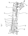
- Fig.1 shows a perspective view of the drive unit without doors 1,2 and door frame 19. Between a side wall 17 left and a side wall right 18 extend in a simple embodiment, a guide rail 7 for the door left parallel to an underlying guide rail 9 for the door right. In a more stable embodiment, the guide rails are replaced by parallel running, superposed guide rail pairs 7,8 and 9,10.
- the guide rail 7 or the pair of guide rails 7, 8 lies in one or, in the case of paired rails, two oblong holes in the sliding unit 3; In order to ensure a low-friction sliding of the sliding unit 3, a sliding or a roller bearing may alternatively be introduced in the oblong holes.
- the sliding units 3, 4 are moved by at least one rotationally driven threaded spindle 11, 12, which with its external thread positively engages in an internal thread 5, 6 arranged parallel to the threaded spindle 11, 12 in the sliding unit 3, 4.
- the rotation of the threaded spindles 11,12 is of a motor gear unit flanged to the ends of the threaded spindle 11,12 and fixed to the outer skin 20 13,14 initiated.
- the motor gear units 13,14 are preferably housed in the side walls 17,18.
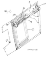
- Fig.2 shows a perspective view of the drive unit with the right door 2 and the door frame 19 in an outer skin 20 of the vehicle from the viewpoint of a looking through the top of the vehicle roof observer.
- the door 2 is in the closed state in the door frame 19.
- the door 2 depends on the support arm 16 which is connected to the sliding unit 4, which in turn slides on the guide rail pairs 9,10 parallel to the driving threaded spindle 12.
- Figure 3 shows a section through the drive unit perpendicular to the guide rails 7,8,9,10 approximately at the height of the line of contact of the two doors 1,2.
- the upper sector shows the drive unit for the left door 1 and the lower sector shows the drive unit for the right door 2.
- the cut sliding unit 3 is slidably mounted on the guide rails 7,8 in the recesses provided for this purpose.
- the threaded spindle 11 is arranged in the internal thread 5.
- the sliding unit 4 cut in this illustration moves the right-hand door 2.
- a threaded spindle 12 is arranged so that an internal thread 6 located in the sliding unit 4 can engage in the external thread of the threaded spindle 12.
- this leads to an opening or closing movement of the door 2, since this is firmly connected via a support arm 16 with the sliding unit 4.
Landscapes
- Engineering & Computer Science (AREA)
- Mechanical Engineering (AREA)
- Power-Operated Mechanisms For Wings (AREA)
- Support Devices For Sliding Doors (AREA)
Applications Claiming Priority (1)
| Application Number | Priority Date | Filing Date | Title |
|---|---|---|---|
| DE102007038564A DE102007038564A1 (de) | 2007-08-16 | 2007-08-16 | Mehrflügelige Schwenkschiebetür mit getrennter Türflügelbetätigung |
Publications (2)
| Publication Number | Publication Date |
|---|---|
| EP2025848A2 true EP2025848A2 (fr) | 2009-02-18 |
| EP2025848A3 EP2025848A3 (fr) | 2014-05-21 |
Family
ID=39870076
Family Applications (1)
| Application Number | Title | Priority Date | Filing Date |
|---|---|---|---|
| EP08014099.9A Withdrawn EP2025848A3 (fr) | 2007-08-16 | 2008-08-07 | Porte coulissante pivotante à plusieurs vantaux dotée d'un actionnement de vantail de porte séparé |
Country Status (2)
| Country | Link |
|---|---|
| EP (1) | EP2025848A3 (fr) |
| DE (1) | DE102007038564A1 (fr) |
Cited By (2)
| Publication number | Priority date | Publication date | Assignee | Title |
|---|---|---|---|---|
| EP2752548A3 (fr) * | 2013-01-02 | 2016-06-22 | Reinhold Schulte | Dispositif d'entraînement d'une porte battante |
| CN108222807A (zh) * | 2018-03-21 | 2018-06-29 | 江苏惠民交通设备有限公司 | 一种丝杆传动的两级伸缩屏蔽门 |
Families Citing this family (1)
| Publication number | Priority date | Publication date | Assignee | Title |
|---|---|---|---|---|
| CN105484600A (zh) * | 2015-12-31 | 2016-04-13 | 苏州绿尚智能科技有限公司 | 一种推窗器 |
Citations (2)
| Publication number | Priority date | Publication date | Assignee | Title |
|---|---|---|---|---|
| DE19946501C2 (de) | 1999-09-28 | 2003-10-16 | Webasto Tuersysteme Gmbh | Schwenkschiebetür |
| DE202005007984U1 (de) | 2005-05-21 | 2006-10-05 | Gebr. Bode Gmbh & Co. Kg | Schiebetür oder Schwenkschiebetür für Fahrzeuge des öffentlichen Personennah- und -fernverkehrs |
Family Cites Families (4)
| Publication number | Priority date | Publication date | Assignee | Title |
|---|---|---|---|---|
| NL282876A (fr) * | 1962-08-30 | 1900-01-01 | ||
| WO1992013300A1 (fr) * | 1991-01-25 | 1992-08-06 | Gilgen Ag | Systeme de commande electronique pour une porte automatique |
| US5893236A (en) * | 1997-05-13 | 1999-04-13 | Westinghouse Air Brake Company | Power operator for sliding plug doors |
| DE20316764U1 (de) * | 2003-10-31 | 2005-03-17 | Bode Gmbh & Co Kg | Schwenkschiebetür für Fahrzeuge, insbesondere Fahrgasttür für Fahrzeuge des öffentlichen Personennahverkehrs |
-
2007
- 2007-08-16 DE DE102007038564A patent/DE102007038564A1/de not_active Withdrawn
-
2008
- 2008-08-07 EP EP08014099.9A patent/EP2025848A3/fr not_active Withdrawn
Patent Citations (2)
| Publication number | Priority date | Publication date | Assignee | Title |
|---|---|---|---|---|
| DE19946501C2 (de) | 1999-09-28 | 2003-10-16 | Webasto Tuersysteme Gmbh | Schwenkschiebetür |
| DE202005007984U1 (de) | 2005-05-21 | 2006-10-05 | Gebr. Bode Gmbh & Co. Kg | Schiebetür oder Schwenkschiebetür für Fahrzeuge des öffentlichen Personennah- und -fernverkehrs |
Cited By (3)
| Publication number | Priority date | Publication date | Assignee | Title |
|---|---|---|---|---|
| EP2752548A3 (fr) * | 2013-01-02 | 2016-06-22 | Reinhold Schulte | Dispositif d'entraînement d'une porte battante |
| CN108222807A (zh) * | 2018-03-21 | 2018-06-29 | 江苏惠民交通设备有限公司 | 一种丝杆传动的两级伸缩屏蔽门 |
| CN108222807B (zh) * | 2018-03-21 | 2024-02-06 | 江苏惠民交通设备有限公司 | 一种丝杆传动的两级伸缩屏蔽门 |
Also Published As
| Publication number | Publication date |
|---|---|
| EP2025848A3 (fr) | 2014-05-21 |
| DE102007038564A1 (de) | 2009-02-19 |
Similar Documents
| Publication | Publication Date | Title |
|---|---|---|
| DE60116660T2 (de) | Mechanismus zur betätigung einer fahrzeugtür | |
| DE2554873C3 (de) | Tür mit Lavierbewegung | |
| DE69216232T2 (de) | Einrichtung für Schwenkschiebetüren für Eisenbahn- und Strassenbahnfahrzeuge | |
| DE102009014869A1 (de) | Schiebe-Schwenktür | |
| EP1584535B1 (fr) | Porte pivotante coulissante pour voitures ferroviaires | |
| EP3052728B1 (fr) | Système de porte coulissante pour une ouverture de porte latérale d'une voiture particulière ; voiture particulière comprenant un système de porte coulissante | |
| EP0837209A2 (fr) | Porte pivotante et coulissante pour véhicules | |
| EP1314626A1 (fr) | Porte coulissante et pivotante pour véhicules, notamment porte des passagers pour véhicules de transport urbain de personnes | |
| DE19943338A1 (de) | Vorrichtung zum Heben und Senken einer Fensterscheibe in einem Kraftfahrzeug | |
| EP1527975A1 (fr) | Porte louvoyante coulissante, notamment porte pour les passagers de véhicules de transport en commun | |
| EP1950078A2 (fr) | Dispositif de translation destiné à l'extraction d'un siège de l'espace intérieur d'un véhicule automobile, dispositif de siège et véhicule automobile doté d'un dispositif de translation | |
| EP0941889B1 (fr) | Dispositif d'extraction | |
| DE3521678C2 (fr) | ||
| DE19946501C2 (de) | Schwenkschiebetür | |
| EP1767389A2 (fr) | Porte pivotante-coulissante pour véhicules de transport de personnes | |
| DE2217784B2 (de) | Fensterheber für Kraftfahrzeuge | |
| DE202005007984U1 (de) | Schiebetür oder Schwenkschiebetür für Fahrzeuge des öffentlichen Personennah- und -fernverkehrs | |
| EP2025848A2 (fr) | Porte coulissante pivotante à plusieurs vantaux dotée d'un actionnement de vantail de porte séparé | |
| DE69100347T2 (de) | Schiebetür und ihr Antriebsmechanismus. | |
| EP1507057A2 (fr) | Porte pivotante et coulissante | |
| DE19819558A1 (de) | Automatische Türanlage | |
| EP4126626B1 (fr) | Dispositif de porte à deux battants pour un véhicule | |
| DE2427334A1 (de) | Schwenkschiebetuer | |
| EP1724138A2 (fr) | Porte coulissante ou pivotante-coulissante pour véhicules de transport urbain et à grande distance de personnes | |
| DE10116583A1 (de) | Ver- und Entriegelungsvorrichtung für Fahrzeugtüren, insbesondere Schwenkschiebetüren für Schienenfahrzeuge |
Legal Events
| Date | Code | Title | Description |
|---|---|---|---|
| PUAI | Public reference made under article 153(3) epc to a published international application that has entered the european phase |
Free format text: ORIGINAL CODE: 0009012 |
|
| AK | Designated contracting states |
Kind code of ref document: A2 Designated state(s): AT BE BG CH CY CZ DE DK EE ES FI FR GB GR HR HU IE IS IT LI LT LU LV MC MT NL NO PL PT RO SE SI SK TR |
|
| AX | Request for extension of the european patent |
Extension state: AL BA MK RS |
|
| PUAL | Search report despatched |
Free format text: ORIGINAL CODE: 0009013 |
|
| AK | Designated contracting states |
Kind code of ref document: A3 Designated state(s): AT BE BG CH CY CZ DE DK EE ES FI FR GB GR HR HU IE IS IT LI LT LU LV MC MT NL NO PL PT RO SE SI SK TR |
|
| AX | Request for extension of the european patent |
Extension state: AL BA MK RS |
|
| RIC1 | Information provided on ipc code assigned before grant |
Ipc: E05F 15/14 20060101ALN20140411BHEP Ipc: E05D 15/58 20060101ALI20140411BHEP Ipc: E05D 15/10 20060101AFI20140411BHEP |
|
| AKY | No designation fees paid | ||
| AXX | Extension fees paid |
Extension state: BA Extension state: AL Extension state: MK Extension state: RS |
|
| REG | Reference to a national code |
Ref country code: DE Ref legal event code: R108 |
|
| REG | Reference to a national code |
Ref country code: DE Ref legal event code: R108 Effective date: 20150128 |
|
| STAA | Information on the status of an ep patent application or granted ep patent |
Free format text: STATUS: THE APPLICATION IS DEEMED TO BE WITHDRAWN |
|
| 18D | Application deemed to be withdrawn |
Effective date: 20141122 |