EP2025025B1 - Interconnector for a fuel cell stack, and method for production - Google Patents
Interconnector for a fuel cell stack, and method for production Download PDFInfo
- Publication number
- EP2025025B1 EP2025025B1 EP07722227A EP07722227A EP2025025B1 EP 2025025 B1 EP2025025 B1 EP 2025025B1 EP 07722227 A EP07722227 A EP 07722227A EP 07722227 A EP07722227 A EP 07722227A EP 2025025 B1 EP2025025 B1 EP 2025025B1
- Authority
- EP
- European Patent Office
- Prior art keywords
- interconnector
- copper
- containing layer
- layer
- steel
- Prior art date
- Legal status (The legal status is an assumption and is not a legal conclusion. Google has not performed a legal analysis and makes no representation as to the accuracy of the status listed.)
- Not-in-force
Links
Images

Classifications
-
- H—ELECTRICITY
- H01—ELECTRIC ELEMENTS
- H01M—PROCESSES OR MEANS, e.g. BATTERIES, FOR THE DIRECT CONVERSION OF CHEMICAL ENERGY INTO ELECTRICAL ENERGY
- H01M8/00—Fuel cells; Manufacture thereof
- H01M8/02—Details
- H01M8/0202—Collectors; Separators, e.g. bipolar separators; Interconnectors
- H01M8/0204—Non-porous and characterised by the material
- H01M8/0206—Metals or alloys
- H01M8/0208—Alloys
- H01M8/021—Alloys based on iron
-
- H—ELECTRICITY
- H01—ELECTRIC ELEMENTS
- H01M—PROCESSES OR MEANS, e.g. BATTERIES, FOR THE DIRECT CONVERSION OF CHEMICAL ENERGY INTO ELECTRICAL ENERGY
- H01M8/00—Fuel cells; Manufacture thereof
- H01M8/10—Fuel cells with solid electrolytes
- H01M8/12—Fuel cells with solid electrolytes operating at high temperature, e.g. with stabilised ZrO2 electrolyte
-
- H—ELECTRICITY
- H01—ELECTRIC ELEMENTS
- H01M—PROCESSES OR MEANS, e.g. BATTERIES, FOR THE DIRECT CONVERSION OF CHEMICAL ENERGY INTO ELECTRICAL ENERGY
- H01M8/00—Fuel cells; Manufacture thereof
- H01M8/02—Details
-
- H—ELECTRICITY
- H01—ELECTRIC ELEMENTS
- H01M—PROCESSES OR MEANS, e.g. BATTERIES, FOR THE DIRECT CONVERSION OF CHEMICAL ENERGY INTO ELECTRICAL ENERGY
- H01M8/00—Fuel cells; Manufacture thereof
- H01M8/02—Details
- H01M8/0202—Collectors; Separators, e.g. bipolar separators; Interconnectors
- H01M8/0204—Non-porous and characterised by the material
- H01M8/0206—Metals or alloys
-
- H—ELECTRICITY
- H01—ELECTRIC ELEMENTS
- H01M—PROCESSES OR MEANS, e.g. BATTERIES, FOR THE DIRECT CONVERSION OF CHEMICAL ENERGY INTO ELECTRICAL ENERGY
- H01M8/00—Fuel cells; Manufacture thereof
- H01M8/02—Details
- H01M8/0202—Collectors; Separators, e.g. bipolar separators; Interconnectors
- H01M8/0204—Non-porous and characterised by the material
- H01M8/0223—Composites
- H01M8/0228—Composites in the form of layered or coated products
-
- H—ELECTRICITY
- H01—ELECTRIC ELEMENTS
- H01M—PROCESSES OR MEANS, e.g. BATTERIES, FOR THE DIRECT CONVERSION OF CHEMICAL ENERGY INTO ELECTRICAL ENERGY
- H01M8/00—Fuel cells; Manufacture thereof
- H01M8/04—Auxiliary arrangements, e.g. for control of pressure or for circulation of fluids
- H01M8/04082—Arrangements for control of reactant parameters, e.g. pressure or concentration
- H01M8/04089—Arrangements for control of reactant parameters, e.g. pressure or concentration of gaseous reactants
-
- H—ELECTRICITY
- H01—ELECTRIC ELEMENTS
- H01M—PROCESSES OR MEANS, e.g. BATTERIES, FOR THE DIRECT CONVERSION OF CHEMICAL ENERGY INTO ELECTRICAL ENERGY
- H01M8/00—Fuel cells; Manufacture thereof
- H01M8/10—Fuel cells with solid electrolytes
- H01M8/12—Fuel cells with solid electrolytes operating at high temperature, e.g. with stabilised ZrO2 electrolyte
- H01M2008/1293—Fuel cells with solid oxide electrolytes
-
- H—ELECTRICITY
- H01—ELECTRIC ELEMENTS
- H01M—PROCESSES OR MEANS, e.g. BATTERIES, FOR THE DIRECT CONVERSION OF CHEMICAL ENERGY INTO ELECTRICAL ENERGY
- H01M4/00—Electrodes
- H01M4/86—Inert electrodes with catalytic activity, e.g. for fuel cells
- H01M4/90—Selection of catalytic material
- H01M4/9041—Metals or alloys
- H01M4/905—Metals or alloys specially used in fuel cell operating at high temperature, e.g. SOFC
- H01M4/9066—Metals or alloys specially used in fuel cell operating at high temperature, e.g. SOFC of metal-ceramic composites or mixtures, e.g. cermets
-
- Y—GENERAL TAGGING OF NEW TECHNOLOGICAL DEVELOPMENTS; GENERAL TAGGING OF CROSS-SECTIONAL TECHNOLOGIES SPANNING OVER SEVERAL SECTIONS OF THE IPC; TECHNICAL SUBJECTS COVERED BY FORMER USPC CROSS-REFERENCE ART COLLECTIONS [XRACs] AND DIGESTS
- Y02—TECHNOLOGIES OR APPLICATIONS FOR MITIGATION OR ADAPTATION AGAINST CLIMATE CHANGE
- Y02E—REDUCTION OF GREENHOUSE GAS [GHG] EMISSIONS, RELATED TO ENERGY GENERATION, TRANSMISSION OR DISTRIBUTION
- Y02E60/00—Enabling technologies; Technologies with a potential or indirect contribution to GHG emissions mitigation
- Y02E60/30—Hydrogen technology
- Y02E60/50—Fuel cells
-
- Y—GENERAL TAGGING OF NEW TECHNOLOGICAL DEVELOPMENTS; GENERAL TAGGING OF CROSS-SECTIONAL TECHNOLOGIES SPANNING OVER SEVERAL SECTIONS OF THE IPC; TECHNICAL SUBJECTS COVERED BY FORMER USPC CROSS-REFERENCE ART COLLECTIONS [XRACs] AND DIGESTS
- Y02—TECHNOLOGIES OR APPLICATIONS FOR MITIGATION OR ADAPTATION AGAINST CLIMATE CHANGE
- Y02P—CLIMATE CHANGE MITIGATION TECHNOLOGIES IN THE PRODUCTION OR PROCESSING OF GOODS
- Y02P70/00—Climate change mitigation technologies in the production process for final industrial or consumer products
- Y02P70/50—Manufacturing or production processes characterised by the final manufactured product
Definitions
- the invention relates to an interconnector for a fuel cell stack and to a method for the production.
- a high-temperature fuel cell converts the chemical energy of a fuel, such as hydrogen or methane, directly into chemical energy.
- a fuel such as hydrogen or methane
- the fuel is oxidized with an oxidizing agent, such as air or pure oxygen.
- an oxygen ion-conducting solid electrolyte such as yttrium-stabilized zirconia.
- the electrolyte is coated with porous, catalytically active electrode materials.
- the anode on the fuel side is a cermet of metallic nickel and zirconia.
- the cathode on the oxidizer side is usually a perovskite based on lanthanum.
- a gas-tight, but electrically conductive interconnector is arranged between two fuel cells.
- This interconnector must have a coefficient of thermal expansion of between 10 * 10 -6 and 12 * 10 -6 K -1 adapted to the other components of the fuel cell. In addition, it must not oxidize in the operating atmospheres of the fuel cell.
- ferritic chromium steels In principle, these requirements are fulfilled by ferritic chromium steels.
- the contacting of the anode with such an interconnector is problematic.
- the protective oxide layer that forms these materials greatly reduces the electrical conductivity of the interconnector.
- nickel-containing agents are generally used for electrical contacting between the interconnector and the anode. Are these agents with the interconnector in Direct contact, disadvantageously degrade both these means and the interconnector after a relatively short period of operation.
- WO 02/058169 A2 is an interconnector for a high-temperature fuel cell, consisting of a ferritic steel, such as FeCrAl, known with a coating of copper.
- the object of the invention is therefore to provide an interconnector for a fuel cell stack, which has an improved durability, especially when in contact with nickel-containing materials.
- an interconnector made of a ferritic chrome steel has been found, on the surface of which a copper-containing layer is arranged, at least in some areas.
- a copper-containing layer As the material for the copper-containing layer, in particular, pure copper or a copper alloy having at least 50 mass percent copper is suitable.
- the copper-containing layer provides improved durability of the interconnector when exposed to aggressive materials such as nickel. Such a situation is given in particular when an electrical contacting means is arranged on the copper-containing layer.
- an electrical contacting means is disposed on the copper-containing layer when the interconnector is used in a fuel cell or in a fuel cell stack.
- the anode of the fuel cell is typically electrically connected to the interconnector by a nickel-containing contacting agent, such as a wire mesh or a mesh of nickel connected.
- the wire mesh or net is attached to the copper-containing layer using conventional joining methods for metallic materials, such as spot welding or soldering.
- the anode of a fuel cell which often contains nickel, can be arranged directly on the interconnector.
- the interconnector contains a chromium-containing oxide layer which further slows down the interdiffusion between the steel and its surroundings, in particular between the steel and a nickel electrical contacting element.
- Interdiffusion between two materials A and B is understood as meaning a reciprocal diffusion of the two materials into one another.
- A diffuses in B, and B diffuses in A.
- the chromium-containing oxide layer can be formed, for example, by diffusing chromium and possibly further elements (such as manganese) from the steel and oxygen from the environment into the copper-containing layer when using the interconnector in a high-temperature fuel cell or during a preoxidation of the interconnector prior to its first use ,
- the chromium-containing oxide layer is disposed within the copper-containing layer. If the interconnector is contacted at some points, then the conductivity of these contact points is not affected by the oxide layer. Due to the high transverse conductivity of the copper-containing layer, a current flow through the interconnector is distributed over the latter Entire cross-sectional area, so that a current supplied via the contact can pass through the interconnector substantially unhindered.
- the oxide layer usually forms approximately in the middle of the copper-containing layer, since the diffusion rates of oxygen, chromium and manganese in copper are about the same size. If one goes from pure copper to alloys with a lower copper content, only the relative position of the oxide layer changes.
- the oxide layer may alternatively be arranged at the interface of the copper-containing layer to the chromium steel. Also in this case, a current flow through the interconnector is not significantly hindered.
- an additional Cr 2 O 3 layer is arranged at the interface of the chromium steel to the copper-containing layer.
- This additional oxide layer forms another barrier to interdiffusion between the interconnector and other devices in contact with it.
- Such a Cr 2 O 3 layer can be formed, for example, by pre-oxidizing the steel prior to application of the copper-containing layer. It advantageously has a thickness of between 0.2 and 3 ⁇ m.
- the copper-containing layer depends on the particular design of the fuel cell as well as on its operating temperature and operating time. It can be determined by the skilled person in a reasonable number of experiments.
- the copper-containing layer including any additional chromium-containing oxide layer, preferably has a thickness between 5 and 1000 ⁇ m, in particular between 10 and 50 ⁇ m.
- the copper-containing layer can be applied by conventional coating methods. For this purpose, for example, sputtering, electrodeposition, plating or spraying methods such as vacuum plasma spraying (VPS), atmospheric plasma spraying (APS) or high-speed flame spraying (HVOF) are suitable.
- VPS vacuum plasma spraying
- APS atmospheric plasma spraying
- HVOF high-speed flame spraying
- the interconnector according to the invention is particularly suitable for use in a fuel cell or in a fuel cell stack.
- the anode of the fuel cell may be connected to the interconnector via an electrical contactor.
- This contacting agent may contain nickel and in particular be a wire mesh or a mesh which is attached by spot welding or soldering on the copper-containing layer.
- the anode of a fuel cell is arranged directly on the copper-containing layer.
- This causes the best possible electrical contact with the interconnector and when used in a fuel cell stack and the adjacent fuel cell.
- the arrangement thereby becomes compact, which is advantageous in particular for fuel cell stacks comprising many individual cells for mobile use.
- this advantageous arrangement is technically meaningful in many cases since the anode of a high-temperature fuel cell often contains nickel in the form of nickel oxide or metallic nickel. According to the prior art, this arrangement has the disadvantage that the nickel damages the steel in the manner described above and, conversely, elements from the steel damage the anode.
- a method for producing an interconnector made of a ferritic chromium steel has been developed.
- a copper-containing layer is applied to the interconnector at least in partial areas of its surface. This prevents in the manner described above, an interdiffusion between the chromium steel and the materials with which the interconnector is in contact.
- chromium diffuses from the interconnector into the copper-containing layer and oxygen from the environment diffuses into the copper-containing layer. They form a chromium-containing oxide layer, which further reduces the interdiffusion between the chromium steel and the surroundings of the interconnector. Where the chromium-containing oxide layer forms depends on the ratio of the diffusion rates of chromium and oxygen. If chromium and oxygen each diffuse unhindered into the copper-containing layer, the oxide layer typically forms in the middle of the copper-containing layer. If the diffusion of chromium from the steel is suppressed by further measures, the oxide layer can also form at the interface of the copper-containing layer to the chromium steel.
- This process is much simpler than the direct production of a triple layer of a copper-containing layer, a chromium-containing oxide layer and another copper-containing layer on the chromium steel.
- the oxide layer advantageously forms during operation. Chromium diffuses, possibly together with other metals such as manganese, from the steel into the copper-containing layer. Oxygen diffuses from the operating atmosphere of the fuel cell into the copper-containing layer.
- the interconnector is subjected to a heat treatment.
- the conditions under which the oxide layer is formed far better controlled than if this is formed at the first use of the interconnector at high temperatures.
- the oxide layer has a higher quality. It is thus more durable and slows the interdiffusion into the steel and out of it stronger.
- the heat treatment is carried out before the application of the copper-containing layer.
- a Cr 2 O 3 layer forms, which is an even better barrier against interdiffusion between the chrome steel and its possibly nickel-containing environment.
- this Cr 2 O 3 layer continues to grow.
- the heat treatment is advantageously carried out at a temperature above 800.degree. C., in particular above 1000.degree.
- the time required for the heat treatment varies between 1 and 100 hours. It depends on the selected temperature; at higher temperatures, shorter times should be chosen as the growth rate of the oxide increases with increasing temperature.
- an oxidation gas is introduced during the heat treatment on the metal layer, whose oxygen partial pressure at the selected temperature is lower than the decomposition pressure of an oxide of the metal M at this temperature. Then it is ensured that the metal M does not oxidize during the heat treatment.
- the oxidizing gas may, for example, be a mixture of 94% by volume of argon, 4% by volume of hydrogen and 2% by volume of water vapor. At a temperature of 800 ° C and copper as metal M, this gas ensures that the copper does not oxidize.
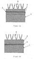
- FIG. 1 shows two embodiments of the interconnector according to the invention.
- the interconnector steel 1 On the interconnector steel 1 are each a copper-containing layer 2 and a chromium-containing oxide layer 3 are arranged.
- the oxide layer 3 In partial image a, the oxide layer 3 is located within the copper-containing layer 2.
- partial image b it is located between interconnector steel 1 and copper-containing layer 2.
- electrical contacting elements 4 made of nickel.
- FIG. 2 shows a cut through the in Figure 1 b sketched embodiment of the interconnector according to the invention.
- the interconnector steel 1 was first preoxidized for 20 hours at 800 ° C. In this case, a mixture of 94 percent by volume of argon, 4 percent by volume of hydrogen and 2 percent by volume of water vapor was presented as the oxidation gas. After the pre-oxidation, the copper-containing layer 2 was applied and the interconnector was oxidized again under the same conditions for 1000 hours. The end product contains a stable oxide layer 3 at the interface between interconnector steel 1 and copper-containing layer 2.
- the oxide layer 3 already arises during the pre-oxidation. It is a two-layered layer of Cr 2 O 3 and Cr 2 MnO 4 . At 800 ° C this layer grows according to a parabolic time law. In the second oxidation after the application of the copper-containing layer 2 to this oxide layer 3, the oxide layer 3 continues to grow.
- the copper-containing layer 2 has no influence on the composition of the two-layer oxide layer 3 of Cr 2 O 3 and Cr 2 MnO 4 . It only affects the growth rate of this layer in the second oxidation, as it affects the diffusion of oxygen.
- the combination of oxide layer and copper-containing layer can also be produced from a copper oxide-containing layer.
- the non-pre-oxidised chromium steel is first provided with the copper oxide-containing layer, which preferably has a thickness between 2 and 30 microns.
- the layer may be applied by conventional coating techniques such as sputtering, plasma spraying, slip casting or suspension.
- the steel is now heat treated, preferably at temperatures between 600 and 900 ° C.
- a reducing gas or gas mixture is preferably introduced in order to create an atmosphere in which copper oxide is thermodynamically unstable.
- the times and other parameters of the heat treatment can be selected as in the pre-oxidation described above.
- the copper oxide is reduced from the outside to copper.
- chromium from the steel will reduce the copper oxide, resulting in the desired oxide layer based on Cr 2 O 3 on the steel.
Abstract
Description
Die Erfindung betrifft einen Interkonnektor für einen Brennstoffzellenstapel und ein Verfahren zur Herstellung.The invention relates to an interconnector for a fuel cell stack and to a method for the production.
Eine Hochtemperaturbrennstoffzelle wandelt die chemische Energie eines Brennstoffs, wie etwa Wasserstoff oder Methan, direkt in chemische Energie um. Hierzu wird der Brennstoff mit einem Oxidationsmittel, wie etwa Luft oder reinem Sauerstoff, oxidiert. Dabei sind Brennstoff und Oxidationsmittel durch einen Sauerstoffionen leitenden Festelektrolyten, wie beispielsweise Yttriumstabilisiertes Zirkoniumoxid, getrennt.A high-temperature fuel cell converts the chemical energy of a fuel, such as hydrogen or methane, directly into chemical energy. For this purpose, the fuel is oxidized with an oxidizing agent, such as air or pure oxygen. In this case, fuel and oxidant are separated by an oxygen ion-conducting solid electrolyte, such as yttrium-stabilized zirconia.
Der Elektrolyt ist mit porösen, katalytisch wirkenden Elektrodenmaterialien beschichtet. Im Allgemeinen ist die Anode auf der Brennstoffseite ein Cermet aus metallischem Nickel und Zirkoniumoxid. Die Kathode auf der Oxidationsmittelseite ist in der Regel ein Perowskit auf Lanthan-Basis.The electrolyte is coated with porous, catalytically active electrode materials. Generally, the anode on the fuel side is a cermet of metallic nickel and zirconia. The cathode on the oxidizer side is usually a perovskite based on lanthanum.
Da eine einzelne Brennstoffzelle nur eine sehr geringe Spannung liefert, müssen für technische Anwendungen viele Zellen zu einem Brennstoffzellenstapel zusammengeschaltet werden. Dazu wird zwischen zwei Brennstoffzellen jeweils ein gasdichter, jedoch elektrisch leitender Interkonnektor angeordnet. Dieser Interkonnektor muss einen an die übrigen Komponenten der Brennstoffzellen angepassten thermischen Ausdehnungskoeffizienten zwischen 10*10-6 und 12*10-6 K-1 aufweisen. Außerdem darf er in den Betriebsatmosphären der Brennstoffzelle nicht oxidieren.Since a single fuel cell provides only a very low voltage, for technical applications, many cells must be interconnected to form a fuel cell stack. For this purpose, a gas-tight, but electrically conductive interconnector is arranged between two fuel cells. This interconnector must have a coefficient of thermal expansion of between 10 * 10 -6 and 12 * 10 -6 K -1 adapted to the other components of the fuel cell. In addition, it must not oxidize in the operating atmospheres of the fuel cell.
Prinzipiell werden diese Anforderungen von ferritischen Chromstählen erfüllt. Die Kontaktierung der Anode mit einem solchen Interkonnektor ist jedoch problematisch. Die schützende Oxidschicht, die diese Werkstoffe bilden, setzt die elektrische Leitfähigkeit des Interkonnektors stark herab. Zudem werden zur elektrischen Kontaktierung zwischen dem Interkonnektor und der Anode in der Regel nickelhaltige Mittel eingesetzt. Stehen diese Mittel mit dem Interkonnektor in direktem Kontakt, degradieren nachteilig sowohl diese Mittel als auch der Interkonnektor schon nach relativ kurzer Betriebszeit.In principle, these requirements are fulfilled by ferritic chromium steels. However, the contacting of the anode with such an interconnector is problematic. The protective oxide layer that forms these materials greatly reduces the electrical conductivity of the interconnector. In addition, nickel-containing agents are generally used for electrical contacting between the interconnector and the anode. Are these agents with the interconnector in Direct contact, disadvantageously degrade both these means and the interconnector after a relatively short period of operation.
Aus
Aufgabe der Erfindung ist daher, einen Interkonnektor für einen Brennstoffzellenstapel zur Verfügung zu stellen, der eine verbesserte Dauerhaltbarkeit insbesondere beim Kontakt mit nickelhaltigen Materialien aufweist.The object of the invention is therefore to provide an interconnector for a fuel cell stack, which has an improved durability, especially when in contact with nickel-containing materials.
Diese Aufgabe wird erfindungsgemäß gelöst durch einen Interkonnektor gemäß Hauptanspruch, eine Verwendung gemäß Nebenanspruch und ein Verfahren gemäß weiterem Nebenanspruch. Weitere vorteilhafte Ausgestaltungen ergeben sich jeweils aus den darauf rückbezogenen Unteransprüchen.This object is achieved by an interconnector according to the main claim, a use according to the independent claim and a method according to further independent claim. Further advantageous embodiments will be apparent from the dependent claims.
Im Rahmen der Erfindung wurde ein Interkonnektor aus einem ferritischen Chromstahl gefunden, auf dessen Oberfläche zumindest in Teilbereichen eine kupferhaltige Schicht angeordnet ist. Als Material für die kupferhaltige Schicht ist insbesondere reines Kupfer oder eine Kupferlegierung mit mindestens 50 Massenprozent Kupfer geeignet.In the context of the invention, an interconnector made of a ferritic chrome steel has been found, on the surface of which a copper-containing layer is arranged, at least in some areas. As the material for the copper-containing layer, in particular, pure copper or a copper alloy having at least 50 mass percent copper is suitable.
Die kupferhaltige Schicht bewirkt eine verbesserte Haltbarkeit des Interkonnektors, wenn er aggressiven Stoffen, wie etwa Nickel, ausgesetzt ist. Eine solche Situation ist insbesondere dann gegeben, wenn auf der kupferhaltigen Schicht ein elektrisches Kontaktierungsmittel angeordnet ist.The copper-containing layer provides improved durability of the interconnector when exposed to aggressive materials such as nickel. Such a situation is given in particular when an electrical contacting means is arranged on the copper-containing layer.
Beispielsweise ist auf der kupferhaltigen Schicht ein elektrisches Kontaktierungsmittel angeordnet, wenn der Interkonnektor in einer Brennstoffzelle oder in einem Brennstoffzellenstapel verwendet wird. Dort wird die Anode der Brennstoffzelle typischerweise durch ein nickelhaltiges Kontaktierungsmittel, wie beispielsweise ein Drahtgeflecht oder ein Netz aus Nickel, elektrisch mit dem Interkonnektor verbunden. Das Drahtgeflecht oder Netz wird dabei mit üblichen Fügeverfahren für metallische Werkstoffe, wie Punktschweißen oder Löten, auf der kupferhaltigen Schicht befestigt.For example, an electrical contacting means is disposed on the copper-containing layer when the interconnector is used in a fuel cell or in a fuel cell stack. There, the anode of the fuel cell is typically electrically connected to the interconnector by a nickel-containing contacting agent, such as a wire mesh or a mesh of nickel connected. The wire mesh or net is attached to the copper-containing layer using conventional joining methods for metallic materials, such as spot welding or soldering.
Alternativ kann unmittelbar auf dem Interkonnektor die Anode einer Brennstoffzelle angeordnet sein, die häufig Nickel enthält.Alternatively, the anode of a fuel cell, which often contains nickel, can be arranged directly on the interconnector.
Die erfindungsgemäß vorgesehene kupferhaltige Schicht bewirkt im Kontakt mit aggressiven Substanzen wie beispielsweise Nickel in dreifacher Hinsicht eine bessere Haltbarkeit der Anordnung.
- 1) Die Diffusion von Elementen aus dem Stahl, insbesondere Chrom und Mangan, über die kupferhaltige Schicht in den Außenraum wird verlangsamt. Diese unerwünschte Diffusion bewirkt nach dem Stand der Technik, dass sich insbesondere auf im Kontakt, mit dem Interkonnektor stehenden Nickel-Oberflächen Chromoxide wie beispielsweise Cr2O3 oder Cr2MnO4 bilden. In Brennstoffzellen hat dies die nachteilige Wirkung, dass die erwünschte katalytische Wirkung dieser Nickel-Oberflächen vermindert wird. Erfindungsgemäß bleibt diese katalytische Wirkung nun über lange Zeit erhalten.
- 2) Die Diffusion von Nickel aus der Umgebung, insbesondere aus einem auf der kupferhaltigen Schicht angeordneten elektrischen Kontaktierungsmittel, in den Stahl wird verlangsamt. Diese unerwünschte Diffusion bewirkt nach dem Stand der Technik, dass der Stahl in eine austenitische Struktur umgewandelt wird, was die Oxidationsbeständigkeit des Stahls beeinträchtigt und gleichzeitig seinen Ausdehnungskoeffizienten unerwünscht erhöht. In der Mehrschichtanordnung in einer Brennstoffzelle führt dies zu thermischen Spannungen und schließlich zu Rissbildungen, so dass die Brennstoffzelle unbrauchbar wird. Erfindungsgemäß bleibt nun die ferritische Struktur des Stahls unverändert, so dass diese Probleme für lange Zeit nicht mehr auftreten.
- 3) Da die unmittelbar an der Oberfläche des Stahls gebildete Oxidschicht nicht mehr mit Nickel aus der Umgebung in Kontakt kommt, kann sie nicht mehr durch Nickel angegriffen werden. Nach dem Stand der Technik kommt der Stahl beispielsweise in direkten Kontakt mit Nickel, wenn auf dem Interkonnektor ein nickelhaltiges elektrisches Kontaktierungsmittel angeordnet ist. An den Kontaktstellen zwischen Stahl und Nickel ist der Stahl nicht mehr gegen Einlagerung von Kohlenstoff geschützt. Der Interkonnektor kommt beispielsweise dann mit Kohlenstoff in Kontakt, wenn er in einer Brennstoffzelle verwendet wird und diese mit einem kohlenstoffhaltigen Brennstoff, wie beispielsweise Methan oder Methanol, betrieben wird. Die Kohlenstoffeinlagerung bewirkt nachteilig eine Aufkohlung des Stahls und versprödet ihn dadurch. Erfindungsgemäß wird nun zum Einen die Oxidschicht auf dem Stahl nicht mehr angegriffen, und zum Anderen schützt die, kupferhaltige Schicht selbst den Stahl vor dem Kontakt mit Kohlenstoff, da Kupfer eine extrem geringe Löslichkeit für Kohlenstoff aufweist. Im Ergebnis wird nahezu kein Kohlenstoff mehr in den Stahl eingelagert, und der Stahl bleibt duktil.
- 1) The diffusion of elements of the steel, especially chromium and manganese, over the copper-containing layer into the outer space is slowed down. According to the prior art, this unwanted diffusion causes chromium oxides such as Cr 2 O 3 or Cr 2 MnO 4 to form, in particular, on nickel surfaces in contact with the interconnector. In fuel cells, this has the adverse effect of reducing the desired catalytic effect of these nickel surfaces. According to the invention, this catalytic effect now remains for a long time.
- 2) The diffusion of nickel from the environment, in particular from an electrical contact means arranged on the copper-containing layer, into the steel is slowed down. This undesirable diffusion causes in the prior art that the steel is converted into an austenitic structure, which impairs the oxidation resistance of the steel and at the same time undesirably increases its coefficient of expansion. In the multilayer arrangement in a fuel cell, this leads to thermal stresses and finally to cracks, so that the fuel cell becomes unusable. According to the invention, the ferritic structure of the steel now remains unchanged, so that these problems no longer occur for a long time.
- 3) Since the oxide layer formed directly on the surface of the steel no longer comes into contact with nickel from the environment, it can no longer be attacked by nickel. According to the state of the art, the steel comes, for example in direct contact with nickel, if a nickel-containing electrical contacting agent is arranged on the interconnector. At the contact points between steel and nickel, the steel is no longer protected against carbon deposits. For example, the interconnector contacts carbon when it is used in a fuel cell and is operated with a carbonaceous fuel such as methane or methanol. Carbon incorporation adversely effects carburization of the steel and thereby embrittles it. According to the invention, on the one hand, the oxide layer on the steel is no longer attacked, and on the other protects the copper-containing layer itself the steel from contact with carbon, since copper has an extremely low solubility for carbon. As a result, almost no more carbon is stored in the steel, and the steel remains ductile.
Vorteilhaft enthält der Interkonnektor eine chromhaltige Oxidschicht, die die Interdiffusion zwischen dem Stahl und seiner Umgebung, insbesondere zwischen dem Stahl und einem elektrischen Kontaktierungselement aus Nickel, noch weiter verlangsamt.Advantageously, the interconnector contains a chromium-containing oxide layer which further slows down the interdiffusion between the steel and its surroundings, in particular between the steel and a nickel electrical contacting element.
Unter Interdiffusion zwischen zwei Materialien A und B wird eine wechselseitige Diffusion der beiden Materialien ineinander verstanden. A diffundiert in B, und B diffundiert in A.Interdiffusion between two materials A and B is understood as meaning a reciprocal diffusion of the two materials into one another. A diffuses in B, and B diffuses in A.
Die chromhaltige Oxidschicht kann beispielsweise gebildet werden, indem beim Einsatz des Interkonnektors in einer Hochtemperaturbrennstoffzelle oder auch bei einer Voroxidation des Interkonnektors vor seiner ersten Verwendung Chrom und eventuell weitere Elemente (wie beispielsweise Mangan) aus dem Stahl sowie Sauerstoff aus der Umgebung in die kupferhaltige Schicht hineindiffundieren.The chromium-containing oxide layer can be formed, for example, by diffusing chromium and possibly further elements (such as manganese) from the steel and oxygen from the environment into the copper-containing layer when using the interconnector in a high-temperature fuel cell or during a preoxidation of the interconnector prior to its first use ,
In einer besonders vorteilhaften Ausgestaltung ist die chromhaltige Oxidschicht innerhalb der kupferhaltigen Schicht angeordnet. Ist der Interkonnektor an einigen Stellen kontaktiert, so ist die Leitfähigkeit dieser Kontaktstellen dann nicht durch die Oxidschicht beeinträchtigt. Durch die hohe Querleitfähigkeit der kupferhaltigen Schicht verteilt sich ein Stromfluss durch den Interkonnektor über dessen gesamte Querschnittsfläche, so dass ein über die Kontaktierung zugeführter Strom den Interkonnektor in Wesentlichen ungehindert passieren kann. Die Oxidschicht bildet sich üblicherweise etwa in der Mitte der kupferhaltigen Schicht, da die Diffusionsraten von Sauerstoff, Chrom und Mangan in Kupfer etwa gleich groß sind. Geht man von reinem Kupfer zu Legierungen mit geringerem Kupfergehalt über, ändert sich nur die relative Lage der Oxidschicht.In a particularly advantageous embodiment, the chromium-containing oxide layer is disposed within the copper-containing layer. If the interconnector is contacted at some points, then the conductivity of these contact points is not affected by the oxide layer. Due to the high transverse conductivity of the copper-containing layer, a current flow through the interconnector is distributed over the latter Entire cross-sectional area, so that a current supplied via the contact can pass through the interconnector substantially unhindered. The oxide layer usually forms approximately in the middle of the copper-containing layer, since the diffusion rates of oxygen, chromium and manganese in copper are about the same size. If one goes from pure copper to alloys with a lower copper content, only the relative position of the oxide layer changes.
Ist die Diffusion von Elementen aus dem Stahl in die kupferhaltige Schicht durch weitere Maßnahmen unterdrückt, kann die Oxidschicht alternativ an der Grenzfläche der kupferhaltigen Schicht zum Chromstahl angeordnet sein. Auch in diesem Fall wird ein Stromfluss durch den Interkonnektor nicht wesentlich behindert.If the diffusion of elements from the steel into the copper-containing layer is suppressed by further measures, the oxide layer may alternatively be arranged at the interface of the copper-containing layer to the chromium steel. Also in this case, a current flow through the interconnector is not significantly hindered.
In einer besonders vorteilhaften Ausgestaltung der Erfindung ist an der Grenzfläche des Chromstahls zur kupferhaltigen Schicht eine zusätzliche Cr2O3-Schicht angeordnet. Diese zusätzliche Oxidschicht bildet eine weitere Barriere gegen Interdiffusion zwischen dem Interkonnektor und weiteren Bauelementen, die mit ihm in Kontakt stehen. Eine solche Cr2O3-Schicht kann beispielsweise gebildet werden, indem der Stahl vor dem Aufbringen der kupferhaltigen Schicht voroxidiert wird. Sie weist vorteilhaft eine Dicke zwischen 0,2 und 3 µm auf.In a particularly advantageous embodiment of the invention, an additional Cr 2 O 3 layer is arranged at the interface of the chromium steel to the copper-containing layer. This additional oxide layer forms another barrier to interdiffusion between the interconnector and other devices in contact with it. Such a Cr 2 O 3 layer can be formed, for example, by pre-oxidizing the steel prior to application of the copper-containing layer. It advantageously has a thickness of between 0.2 and 3 μm.
Die sinnvolle Dicke der kupferhaltigen Schicht hängt von der jeweiligen Konstruktion der Brennstoffzellen sowie von deren Betriebstemperatur und Betriebsdauer ab. Sie kann durch den Fachmann in einer zumutbaren Anzahl Versuche ermittelt werden. Vorzugsweise weist die kupferhaltige Schicht, einschließlich einer eventuellen zusätzlichen chromhaltigen Oxidschicht, jedoch eine Dicke zwischen 5 und 1000 µm, insbesondere zwischen 10 und 50 µm, auf. Die kupferhaltige Schicht kann mit konventionellen Beschichtungsverfahren aufgebracht werden. Hierfür sind beispielsweise Sputtern, galvanische Abscheidung, Plattieren oder auch Spritzverfahren wie Vakuumplasmaspritzen (VPS), atmosphärisches Plasmaspritzen (APS) oder Hochgeschwindigkeitsflammspritzen (HVOF) geeignet.The reasonable thickness of the copper-containing layer depends on the particular design of the fuel cell as well as on its operating temperature and operating time. It can be determined by the skilled person in a reasonable number of experiments. However, the copper-containing layer, including any additional chromium-containing oxide layer, preferably has a thickness between 5 and 1000 μm, in particular between 10 and 50 μm. The copper-containing layer can be applied by conventional coating methods. For this purpose, for example, sputtering, electrodeposition, plating or spraying methods such as vacuum plasma spraying (VPS), atmospheric plasma spraying (APS) or high-speed flame spraying (HVOF) are suitable.
Der erfindungsgemäße Interkonnektor eignet sich besonders zur Verwendung in einer Brennstoffzelle oder in einem Brennstoffzellenstapel. Bei einer solchen Verwendung kann die Anode der Brennstoffzelle über ein elektrisches Kontaktierungsmittel mit dem Interkonnektor verbunden werden. Dieses Kontaktierungsmittel kann Nickel enthalten und insbesondere ein Drahtgeflecht oder ein Netz sein, welches mittels Punktschweißen oder Löten auf der kupferhaltigen Schicht befestigt ist.The interconnector according to the invention is particularly suitable for use in a fuel cell or in a fuel cell stack. In such use, the anode of the fuel cell may be connected to the interconnector via an electrical contactor. This contacting agent may contain nickel and in particular be a wire mesh or a mesh which is attached by spot welding or soldering on the copper-containing layer.
Alternativ ist unmittelbar auf der kupferhaltigen Schicht die Anode einer Brennstoffzelle angeordnet. Dies bewirkt eine bestmögliche elektrische Kontaktierung zum Interkonnektor und bei Verwendung in einem Brennstoffzellenstapel auch zur benachbarten Brennstoffzelle. Zugleich wird die Anordnung hierdurch kompakt, was insbesondere für Brennstoffzellenstapel aus vielen Einzelzellen zum mobilen Einsatz von Vorteil ist. Durch die erfindungsgemäße kupferhaltige Schicht wird diese vorteilhafte Anordnung in vielen Fällen überhaupt erst technisch sinnvoll, denn die Anode einer Hochtemperaturbrennstoffzelle enthält häufig Nickel in Form von Nickeloxid oder metallischem Nickel. Nach dem Stand der Technik muss bei dieser Anordnung der Nachteil in Kauf genommen werden, dass das Nickel auf die oben beschriebene Weise den Stahl schädigt und umgekehrt Elemente aus dem Stahl die Anode schädigen.Alternatively, the anode of a fuel cell is arranged directly on the copper-containing layer. This causes the best possible electrical contact with the interconnector and when used in a fuel cell stack and the adjacent fuel cell. At the same time, the arrangement thereby becomes compact, which is advantageous in particular for fuel cell stacks comprising many individual cells for mobile use. As a result of the copper-containing layer according to the invention, this advantageous arrangement is technically meaningful in many cases since the anode of a high-temperature fuel cell often contains nickel in the form of nickel oxide or metallic nickel. According to the prior art, this arrangement has the disadvantage that the nickel damages the steel in the manner described above and, conversely, elements from the steel damage the anode.
An Stelle von Kupfer können auch andere metallische Elemente oder Legierungen verwendet werden. Geeignet sind insbesondere Materialien, die
- bei der Betriebstemperatur einer Hochtemperaturbrennstoffzelle nicht oder nur geringfügig in den Stahl diffundieren,
- bei der Betriebstemperatur oder der Temperatur, bei der der Stahl voroxidiert wird, vergleichbare Löslichkeiten für Chrom, Mangan und Sauerstoff aufweisen sowie
- in der Betriebsatmosphäre der Brennstoffzelle nicht oxidieren.
- at the operating temperature of a high temperature fuel cell do not or only slightly diffuse into the steel,
- at the operating temperature or at the temperature at which the steel is preoxidized, have comparable solubilities for chromium, manganese and oxygen as well as
- do not oxidize in the operating atmosphere of the fuel cell.
Diese Bedingungen werden beispielsweise von Kupferlegierungen mit mindestens 50 Massenprozent Kupfer erfüllt.These conditions are met, for example, by copper alloys containing at least 50 percent copper by weight.
Im Rahmen der Erfindung wurde ein Verfahren zur Herstellung eines Interkonnektors aus einem ferritischen Chromstahl entwickelt. Bei diesem Verfahren wird auf dem Interkonnektor zumindest in Teilbereichen seiner Oberfläche eine kupferhaltige Schicht aufgebracht. Diese verhindert auf die oben beschriebene Weise eine Interdiffusion zwischen dem Chromstahl und den Materialien, mit denen der Interkonnektor in Kontakt steht.In the context of the invention, a method for producing an interconnector made of a ferritic chromium steel has been developed. In this method, a copper-containing layer is applied to the interconnector at least in partial areas of its surface. This prevents in the manner described above, an interdiffusion between the chromium steel and the materials with which the interconnector is in contact.
In einer besonders vorteilhaften Ausgestaltung der Erfindung diffundieren Chrom aus dem Interkonnektor in die kupferhaltige Schicht und Sauerstoff aus der Umgebung in die kupferhaltige Schicht. Sie bilden dabei eine chromhaltige Oxidschicht, die die Interdiffusion zwischen dem Chromstahl und der Umgebung des Interkonnektors weiter vermindert. Wo sich die chromhaltige Oxidschicht bildet, hängt vom Verhältnis der Diffusionsgeschwindigkeiten von Chrom und Sauerstoff ab. Diffundieren Chrom und Sauerstoff jeweils ungehindert in die kupferhaltige Schicht, bildet sich die Oxidschicht typischerweise in der Mitte der kupferhaltigen Schicht. Wird die Diffusion von Chrom aus dem Stahl durch weitere Maßnahmen unterdrückt, kann sich die Oxidschicht aber auch an der Grenzfläche der kupferhaltigen Schicht zum Chromstahl bilden.In a particularly advantageous embodiment of the invention, chromium diffuses from the interconnector into the copper-containing layer and oxygen from the environment diffuses into the copper-containing layer. They form a chromium-containing oxide layer, which further reduces the interdiffusion between the chromium steel and the surroundings of the interconnector. Where the chromium-containing oxide layer forms depends on the ratio of the diffusion rates of chromium and oxygen. If chromium and oxygen each diffuse unhindered into the copper-containing layer, the oxide layer typically forms in the middle of the copper-containing layer. If the diffusion of chromium from the steel is suppressed by further measures, the oxide layer can also form at the interface of the copper-containing layer to the chromium steel.
Dieses Verfahren ist wesentlich einfacher als die direkte Herstellung einer Dreifachschicht aus einer kupferhaltigen Schicht, einer chromhaltigen Oxidschicht und einer weiteren kupferhaltigen Schicht auf dem Chromstahl. Wird der Interkonnektor beispielsweise in einer Hochtemperaturbrennstoffzelle eingesetzt, bildet sich die Oxidschicht vorteilhaft während des Betriebs aus. Chrom diffundiert, eventuell zusammen mit weiteren Metallen wie etwa Mangan, vom Stahl in die kupferhaltige Schicht. Sauerstoff diffundiert aus der Betriebsatmosphäre der Brennstoffzelle in die kupferhaltige Schicht.This process is much simpler than the direct production of a triple layer of a copper-containing layer, a chromium-containing oxide layer and another copper-containing layer on the chromium steel. If the interconnector is used, for example, in a high-temperature fuel cell, the oxide layer advantageously forms during operation. Chromium diffuses, possibly together with other metals such as manganese, from the steel into the copper-containing layer. Oxygen diffuses from the operating atmosphere of the fuel cell into the copper-containing layer.
Neben Kupfer sind Elemente und Legierungen geeignet, die
- bei der Betriebstemperatur einer Hochtemperaturbrennstoffzelle nicht oder nur geringfügig in den Stahl diffundieren,
- bei der Betriebstemperatur oder der Temperatur, bei der der Stahl voroxidiert wird, vergleichbare Löslichkeiten für Chrom, Mangan und Sauerstoff aufweisen sowie
- in der Betriebsatmosphäre der Brennstoffzelle nicht oxidieren.
- at the operating temperature of a high temperature fuel cell do not or only slightly diffuse into the steel,
- at the operating temperature or at the temperature at which the steel is preoxidized, have comparable solubilities for chromium, manganese and oxygen as well as
- do not oxidize in the operating atmosphere of the fuel cell.
Diese Bedingungen werden beispielsweise von Kupferlegierungen mit mindestens 50 Massenprozent Kupfer erfüllt.These conditions are met, for example, by copper alloys containing at least 50 percent copper by weight.
Vorteilhaft wird der Interkonnektor einer Wärmebehandlung unterzogen. Dabei können die Bedingungen, unter denen sich die Oxidschicht bildet, weitaus besser kontrolliert werden als wenn diese beim ersten Einsatz des Interkonnektors bei hohen Temperaturen gebildet wird. Im Ergebnis weist die Oxidschicht eine höhere Qualität auf. Sie ist somit länger haltbar und verlangsamt die Interdiffusion in den Stahl hinein und aus ihm heraus stärker.Advantageously, the interconnector is subjected to a heat treatment. In this case, the conditions under which the oxide layer is formed, far better controlled than if this is formed at the first use of the interconnector at high temperatures. As a result, the oxide layer has a higher quality. It is thus more durable and slows the interdiffusion into the steel and out of it stronger.
In einer besonders vorteilhaften Ausgestaltung der Erfindung wird die Wärmebehandlung vor dem Aufbringen der kupferhaltigen Schicht durchgeführt. Dann bildet sich auf dem Chromstahl eine Cr2O3-Schicht, die eine noch bessere Barriere gegen Interdiffusion zwischen dem Chromstahl und seiner möglicherweise nickelhaltigen Umgebung darstellt. Beim Hochtemperatureinsatz nach Aufbringen der kupferhaltigen Schicht wächst diese Cr2O3-Schicht weiter. Es entsteht jedoch keine Oxidschicht innerhalb der kupferhaltigen Schicht, sondern nur an der Grenzfläche zwischen dem Stahl und der kupferhaltigen Schicht.In a particularly advantageous embodiment of the invention, the heat treatment is carried out before the application of the copper-containing layer. Then, on the chromium steel, a Cr 2 O 3 layer forms, which is an even better barrier against interdiffusion between the chrome steel and its possibly nickel-containing environment. During high-temperature use after application of the copper-containing layer, this Cr 2 O 3 layer continues to grow. However, there is no oxide layer within the copper-containing layer, but only at the interface between the steel and the copper-containing layer.
Die Wärmebehandlung wird vorteilhaft bei einer Temperatur oberhalb von 800 °C, insbesondere oberhalb von 1000 °C, durchgeführt. Die nötige Zeit für die Wärmebehandlung variiert zwischen 1 und 100 Stunden. Sie richtet sich nach der gewählten Temperatur; bei höheren Temperaturen sollten kürzere Zeiten gewählt werden, da die Wachstumsrate des Oxids mit steigender Temperatur zunimmt.The heat treatment is advantageously carried out at a temperature above 800.degree. C., in particular above 1000.degree. The time required for the heat treatment varies between 1 and 100 hours. It depends on the selected temperature; at higher temperatures, shorter times should be chosen as the growth rate of the oxide increases with increasing temperature.
Vorteilhaft wird während der Wärmebehandlung an der Metallschicht ein Oxidationsgas vorgelegt, dessen Sauerstoffpartialdruck bei der gewählten Temperatur geringer ist als der Zersetzungsdruck eines Oxids aus dem Metall M bei dieser Temperatur. Dann ist sichergestellt, dass das Metall M während der Wärmebehandlung nicht oxidiert. Das Oxidationsgas kann beispielsweise ein Gemisch aus 94 Volumenprozent Argon, 4 Volumenprozent Wasserstoff und 2 Volumenprozent Wasserdampf sein. Bei einer Temperatur von 800 °C und Kupfer als Metall M ist mit diesem Gas sichergestellt, dass das Kupfer nicht oxidiert.Advantageously, an oxidation gas is introduced during the heat treatment on the metal layer, whose oxygen partial pressure at the selected temperature is lower than the decomposition pressure of an oxide of the metal M at this temperature. Then it is ensured that the metal M does not oxidize during the heat treatment. The oxidizing gas may, for example, be a mixture of 94% by volume of argon, 4% by volume of hydrogen and 2% by volume of water vapor. At a temperature of 800 ° C and copper as metal M, this gas ensures that the copper does not oxidize.
Nachfolgend wird der Gegenstand der Erfindung anhand von Figuren näher erläutert, ohne dass der Gegenstand der Erfindung dadurch beschränkt wird. Es ist gezeigt:
- Figur 1:
- Zwei Ausführungsfonnen des erfindungsgemäßen Interkonnektors
mit elektrischen Kontaktierungselementen 4 aus Nickel. Teilbild a: mit einerOxidschicht 3 innerhalb der kupferhaltigen Schicht 2. Teil- bild b: mit einerOxidschicht 3zwischen Interkonnektorstahl 1 und kupferhaltiger Schicht 2. - Figur 2:
- Schliff durch die in
Figur 1 b skizzierte Ausführungsform des erfin- dungsgemäßen Interkonnektors.
- FIG. 1:
- Two embodiments of the interconnector according to the invention with electrical contacting
elements 4 made of nickel. Partial image a: with anoxide layer 3 within the copper-containinglayer 2. Partial image b: with anoxide layer 3 betweeninterconnector steel 1 and copper-containinglayer 2. - FIG. 2:
- Cut through the in
Figure 1 b sketched embodiment of the inventive interconnector.
Die Oxidschicht 3 entsteht bereits bei der Voroxidation. Sie ist eine zweilagige Schicht aus Cr2O3 und Cr2MnO4. Bei 800°C wächst diese Schicht etwa nach einem parabolischen Zeitgesetz. Bei der zweiten Oxidation nach dem Aufbringen der kupferhaltigen Schicht 2 auf diese Oxidschicht 3 wächst die Oxidschicht 3 weiter. Die kupferhaltige Schicht 2 hat keinen Einfluss auf die Zusammensetzung der zweilagigen Oxidschicht 3 aus Cr2O3 und Cr2MnO4. Sie beeinflusst nur die Wachstumsrate dieser Schicht bei der zweiten Oxidation, da sie die Diffusion des Sauerstoffs beeinflusst.The
Alternativ kann die Kombination aus Oxidschicht und kupferhaltiger Schicht auch aus einer kupferoxidhaltigen Schicht erzeugt werden. Hierzu wird der nicht voroxidierte Chromstahl zunächst mit der kupferoxidhaltigen Schicht versehen, welche vorzugsweise eine Dicke zwischen 2 und 30 µm aufweist. Die Schicht kann über herkömmliche Beschichtungsverfahren, wie beispielsweise Sputtern, Plasmaspritzen, Schlickerguss oder als Suspension, aufgebracht werden.Alternatively, the combination of oxide layer and copper-containing layer can also be produced from a copper oxide-containing layer. For this purpose, the non-pre-oxidised chromium steel is first provided with the copper oxide-containing layer, which preferably has a thickness between 2 and 30 microns. The layer may be applied by conventional coating techniques such as sputtering, plasma spraying, slip casting or suspension.
Der Stahl wird nun wärmebehandelt, vorzugsweise bei Temperaturen zwischen 600 und 900°C. Hierbei wird vorzugsweise ein reduzierendes Gas oder Gasgemisch vorgelegt, um eine Atmosphäre zu schaffen, in der Kupferoxid thermodynamisch nicht stabil ist. Die Zeiten und sonstigen Parameter der Wärmebehandlung können wie bei der oben beschriebenen Voroxidation gewählt werden.The steel is now heat treated, preferably at temperatures between 600 and 900 ° C. In this case, a reducing gas or gas mixture is preferably introduced in order to create an atmosphere in which copper oxide is thermodynamically unstable. The times and other parameters of the heat treatment can be selected as in the pre-oxidation described above.
Während der Wärmebehandlung wird das Kupferoxid von der Außenseite her zu Kupfer reduziert. An der Grenzfläche zum Stahl wird Chrom aus dem Stahl das Kupferoxid reduzieren, wobei auf dem Stahl die gewünschte Oxidschicht auf Basis von Cr2O3 entsteht.During the heat treatment, the copper oxide is reduced from the outside to copper. At the interface with the steel, chromium from the steel will reduce the copper oxide, resulting in the desired oxide layer based on Cr 2 O 3 on the steel.
Claims (15)
- Interconnector for a fuel cell made of a ferritic chromium steel (1), characterised by a copper containing layer made of copper or a copper alloy (2) arranged at least in part areas of its surface, characterised in that
an additional chromium containing oxide layer made of Cr2O3 (3) is arranged in the border area between the copper containing layer (2) and the chromium steel (1). - Interconnector according to claim 1, characterised by at least 50 percent by mass of copper in the copper containing layer (2).
- Interconnector according to claim 3, characterised in that a further oxide layer (3) is arranged in the copper containing layer.
- Interconnector according to one of claims 1 to 3, characterised by a thickness of the Cr2O3 layer (3) of between 0.2 and 3 µm.
- Interconnector according to one of claims 1 to 4, characterised by a thickness of the copper containing layer (2) including the additional chromium containing Cr2O3 oxide layer (3) of between 5 and 1000 µm.
- Interconnector according to claim 5, characterised by a thickness of the copper containing layer (2) including the additional chromium containing Cr2O3 oxide layer (3) of between 10 and 50 µm.
- Interconnector according to one of claims 1 to 5, characterised by at least one electrical means of contacting (4), which is arranged on the copper containing layer (2).
- Interconnector according to claim 6, characterised by a nickel containing means of contacting (4).
- Interconnector according to claim 7, characterised by a wire mesh or network made of nickel as the means of contacting (4).
- Interconnector according to claim 8, characterised in that the wire mesh or network is fastened to the copper containing layer (2) by means of spot welding or soldering.
- Interconnector according to one of claims 1 to 9, characterised in that the anode of a fuel cell is arranged directly on the copper containing layer (2).
- Method for the production of an interconnector for a fuel cell (1) according to one of claims 1 to 8, in which a copper containing layer (2) made of copper or a copper alloy is applied at least in part areas of its surface, characterised in that the interconnector is subject to heat treatment before application of the copper containing layer (2).
- Method according to claim 12, characterised in that the heat treatment is carried out at a temperature over 800° C, particularly over 1000° C.
- Method according to one of claims 12 to 13, characterised in that a mixture or 94 percent by volume of argon, 4 percent by volume of hydrogen and 2 percent by volume of steam is supplied as the oxidation gas during heat treatment.
- Method according to one of claims 12 to 14, characterised in that chromium from the interconnector (1) is diffused into the copper containing layer (2) and in this way forms a further oxide layer (3) in the copper containing layer (2).
Applications Claiming Priority (2)
| Application Number | Priority Date | Filing Date | Title |
|---|---|---|---|
| DE102006024039A DE102006024039A1 (en) | 2006-05-23 | 2006-05-23 | Interconnector for a fuel cell stack and method of manufacture |
| PCT/DE2007/000669 WO2007134560A1 (en) | 2006-05-23 | 2007-04-18 | Interconnector for a fuel cell stack, and method for production |
Publications (2)
| Publication Number | Publication Date |
|---|---|
| EP2025025A1 EP2025025A1 (en) | 2009-02-18 |
| EP2025025B1 true EP2025025B1 (en) | 2011-02-16 |
Family
ID=38480479
Family Applications (1)
| Application Number | Title | Priority Date | Filing Date |
|---|---|---|---|
| EP07722227A Not-in-force EP2025025B1 (en) | 2006-05-23 | 2007-04-18 | Interconnector for a fuel cell stack, and method for production |
Country Status (8)
| Country | Link |
|---|---|
| US (1) | US8232020B2 (en) |
| EP (1) | EP2025025B1 (en) |
| JP (1) | JP5199245B2 (en) |
| KR (1) | KR101356596B1 (en) |
| CN (1) | CN101454932B (en) |
| AT (1) | ATE498918T1 (en) |
| DE (2) | DE102006024039A1 (en) |
| WO (1) | WO2007134560A1 (en) |
Families Citing this family (9)
| Publication number | Priority date | Publication date | Assignee | Title |
|---|---|---|---|---|
| DE102008049712A1 (en) * | 2008-09-30 | 2010-04-01 | Siemens Aktiengesellschaft | Planar high-temperature fuel cell |
| JP5711093B2 (en) * | 2011-10-12 | 2015-04-30 | 一般財団法人ファインセラミックスセンター | Gas separation material for solid oxide fuel cell and solid oxide fuel cell |
| TWI632728B (en) | 2013-11-27 | 2018-08-11 | 博隆能源股份有限公司 | Fuel cell interconnect with reduced voltage degradation over time and associated method |
| WO2015130644A1 (en) | 2014-02-25 | 2015-09-03 | Bloom Energy Corporation | Composition and processing of metallic interconnects for sofc stacks |
| US9923211B2 (en) | 2014-04-24 | 2018-03-20 | Bloom Energy Corporation | Fuel cell interconnect with reduced voltage degradation over time |
| JP7249943B2 (en) | 2016-12-16 | 2023-03-31 | トプソー・アクチエゼルスカベット | Improved contact between interconnects and cells in solid oxide cell stacks |
| AU2017374799B2 (en) * | 2016-12-16 | 2023-06-22 | Haldor Topsøe A/S | Deposition of a coating on an interconnect for solid oxide cell stacks |
| CN109473694A (en) * | 2018-10-16 | 2019-03-15 | 中国科学院金属研究所 | Solid oxide fuel cell stainless steel connector surface protection coating and its preparation |
| AU2022268645A1 (en) | 2021-05-06 | 2023-10-12 | Topsoe A/S | Interconnect for solid oxide cell (soc) |
Family Cites Families (18)
| Publication number | Priority date | Publication date | Assignee | Title |
|---|---|---|---|---|
| JP2790653B2 (en) * | 1989-04-28 | 1998-08-27 | 日本碍子株式会社 | Conductive intermediate connector and fuel cell having the same |
| AUPO724997A0 (en) * | 1997-06-10 | 1997-07-03 | Ceramic Fuel Cells Limited | A fuel cell assembly |
| US6326096B1 (en) * | 1998-02-04 | 2001-12-04 | Gas Research Institute | Solid oxide fuel cell interconnector |
| DE19913873A1 (en) * | 1999-03-26 | 2000-05-25 | Siemens Ag | High temperature fuel cell has an interconnector coated with a nickel layer and an overlying layer to prevent oxidation |
| EP1175705A1 (en) * | 1999-03-26 | 2002-01-30 | Siemens Aktiengesellschaft | High-temperature fuel cell |
| CN2400908Y (en) * | 1999-12-10 | 2000-10-11 | 中国科学院上海硅酸盐研究所 | Anode film-connection board struture for use in solid oxide fuel cell stack |
| JP4776147B2 (en) * | 2000-11-09 | 2011-09-21 | トラスティーズ オブ ザ ユニヴァーシティ オブ ペンシルヴァニア | Solid oxide fuel cell and electric energy production method |
| JP2003187828A (en) * | 2001-12-20 | 2003-07-04 | Nisshin Steel Co Ltd | Ferritic stainless steel for solid oxide type fuel cell member |
| JP2003243001A (en) * | 2002-02-14 | 2003-08-29 | Toto Ltd | Solid electrolyte fuel cell |
| GB2386126B (en) * | 2002-03-06 | 2006-03-08 | Ceres Power Ltd | Forming an impermeable sintered ceramic electrolyte layer on a metallic foil substrate for solid oxide fuel cell |
| US7842434B2 (en) * | 2005-06-15 | 2010-11-30 | Ati Properties, Inc. | Interconnects for solid oxide fuel cells and ferritic stainless steels adapted for use with solid oxide fuel cells |
| DE10306649A1 (en) * | 2003-02-18 | 2004-09-02 | Forschungszentrum Jülich GmbH | Protective layer for substrates exposed to high temperatures, and method for producing the same |
| DE10306647A1 (en) * | 2003-02-18 | 2004-09-02 | Forschungszentrum Jülich GmbH | Manufacturing process for a protective layer for chromium oxide-forming substrates exposed to high temperatures |
| JP4018039B2 (en) * | 2003-08-29 | 2007-12-05 | 東京瓦斯株式会社 | Fe-Cr-Al heat-resistant alloy for solid oxide fuel cells |
| JP2008504437A (en) * | 2004-06-25 | 2008-02-14 | ゼネラル・モーターズ・コーポレーション | Stainless steel alloy and bipolar plate |
| JP4719940B2 (en) * | 2004-12-27 | 2011-07-06 | Toto株式会社 | Interconnector material and solid oxide fuel cell having the same |
| CN1667859A (en) * | 2005-04-15 | 2005-09-14 | 哈尔滨工业大学 | Process for preparing solid oxide fuel battery connectors |
| KR101258715B1 (en) * | 2005-06-15 | 2013-04-30 | 에이티아이 프로퍼티즈, 인코퍼레이티드 | Interconnects for solid oxide fuel cells and ferritic stainless steels adapted for use with solid oxide fuel cells |
-
2006
- 2006-05-23 DE DE102006024039A patent/DE102006024039A1/en not_active Withdrawn
-
2007
- 2007-04-18 EP EP07722227A patent/EP2025025B1/en not_active Not-in-force
- 2007-04-18 KR KR1020087029044A patent/KR101356596B1/en not_active IP Right Cessation
- 2007-04-18 US US12/227,537 patent/US8232020B2/en not_active Expired - Fee Related
- 2007-04-18 WO PCT/DE2007/000669 patent/WO2007134560A1/en active Application Filing
- 2007-04-18 CN CN2007800183547A patent/CN101454932B/en not_active Expired - Fee Related
- 2007-04-18 AT AT07722227T patent/ATE498918T1/en active
- 2007-04-18 DE DE502007006504T patent/DE502007006504D1/en active Active
- 2007-04-18 JP JP2009511327A patent/JP5199245B2/en not_active Expired - Fee Related
Also Published As
| Publication number | Publication date |
|---|---|
| US20090253020A1 (en) | 2009-10-08 |
| KR20090010082A (en) | 2009-01-28 |
| KR101356596B1 (en) | 2014-02-03 |
| DE502007006504D1 (en) | 2011-03-31 |
| US8232020B2 (en) | 2012-07-31 |
| JP5199245B2 (en) | 2013-05-15 |
| CN101454932A (en) | 2009-06-10 |
| DE102006024039A1 (en) | 2007-11-29 |
| ATE498918T1 (en) | 2011-03-15 |
| JP2009537958A (en) | 2009-10-29 |
| CN101454932B (en) | 2012-10-10 |
| WO2007134560A1 (en) | 2007-11-29 |
| EP2025025A1 (en) | 2009-02-18 |
Similar Documents
| Publication | Publication Date | Title |
|---|---|---|
| EP2025025B1 (en) | Interconnector for a fuel cell stack, and method for production | |
| EP1595301B1 (en) | Protective coating for substrates that are subjected to high temperatures and method for producing said coating | |
| EP1287571B1 (en) | Material used at high temperatures | |
| EP1984533B1 (en) | Creep-resistant ferritic steel | |
| EP0868759B1 (en) | Selectively coated bipolar plate | |
| EP1595302B1 (en) | Method for producing a protective coating for substrates that are subjected to high temperatures and form chromium oxide | |
| EP1844513B1 (en) | Interconnector for high-temperature fuel cells | |
| DE112009001684B4 (en) | Fuel cell separator and fuel cell | |
| DE102006045086A1 (en) | Electrochemical cell structures and process for their preparation | |
| DE102016102179A1 (en) | Multilayer coating for a corrosion-resistant metal bipolar plate for a proton exchange membrane fuel cell (PEMFC) | |
| EP1915793B1 (en) | Protection for anode-supported high-temperature fuel cells against reoxidation of the anode | |
| DE10050010A1 (en) | Interconnector used for high temperature fuel cells has an oxidic protective layer based on manganese oxide and/or cobalt oxide applied on its surface | |
| EP2335314B1 (en) | Planar high-temperature fuel cell | |
| WO2010037670A1 (en) | Tubular high-temperature fuel cell, method for the manufacture thereof and fuel cell system comprising the same | |
| DE102006056251B4 (en) | High temperature fuel cell with ferritic component and method of operating the same | |
| DE102009037206B4 (en) | Method for producing a bipolar plate for a fuel cell stack and bipolar plate for a fuel cell stack | |
| DE102007058907A1 (en) | Process to manufacture a solid oxide fuel cell with a steel substrate coated with metals from the transition group except chrome | |
| EP1206807A1 (en) | Electrical bonding protected against oxidation on the gas combustion side of a high temperature fuel cell | |
| DE102008032498A1 (en) | Chromium-containing metal substrates, especially for use in high temperature fuel cells, have chromium-free electroless coating containing one or more transition metals (excluding chromium) or noble metals | |
| EP3697944B1 (en) | Fuel gas electrode and method for producing a fuel gas electrode | |
| DE102009037207A1 (en) | Method for connecting bipolar plate with electrode, cathode electrolyte of anode unit and other component of fuel cell stack, involves coating base material of bipolar plate with coating material |
Legal Events
| Date | Code | Title | Description |
|---|---|---|---|
| PUAI | Public reference made under article 153(3) epc to a published international application that has entered the european phase |
Free format text: ORIGINAL CODE: 0009012 |
|
| 17P | Request for examination filed |
Effective date: 20081025 |
|
| AK | Designated contracting states |
Kind code of ref document: A1 Designated state(s): AT BE BG CH CY CZ DE DK EE ES FI FR GB GR HU IE IS IT LI LT LU LV MC MT NL PL PT RO SE SI SK TR |
|
| AX | Request for extension of the european patent |
Extension state: AL BA HR MK RS |
|
| RIN1 | Information on inventor provided before grant (corrected) |
Inventor name: SINGHEISER, LORENZ Inventor name: NIEWOLAK, LESZEK Inventor name: QUADAKKERS, WILLEM, J. |
|
| 17Q | First examination report despatched |
Effective date: 20090424 |
|
| GRAP | Despatch of communication of intention to grant a patent |
Free format text: ORIGINAL CODE: EPIDOSNIGR1 |
|
| DAX | Request for extension of the european patent (deleted) | ||
| GRAS | Grant fee paid |
Free format text: ORIGINAL CODE: EPIDOSNIGR3 |
|
| GRAA | (expected) grant |
Free format text: ORIGINAL CODE: 0009210 |
|
| AK | Designated contracting states |
Kind code of ref document: B1 Designated state(s): AT BE BG CH CY CZ DE DK EE ES FI FR GB GR HU IE IS IT LI LT LU LV MC MT NL PL PT RO SE SI SK TR |
|
| REG | Reference to a national code |
Ref country code: GB Ref legal event code: FG4D Free format text: NOT ENGLISH |
|
| REG | Reference to a national code |
Ref country code: CH Ref legal event code: EP |
|
| REG | Reference to a national code |
Ref country code: IE Ref legal event code: FG4D Free format text: LANGUAGE OF EP DOCUMENT: GERMAN |
|
| REF | Corresponds to: |
Ref document number: 502007006504 Country of ref document: DE Date of ref document: 20110331 Kind code of ref document: P |
|
| REG | Reference to a national code |
Ref country code: DE Ref legal event code: R096 Ref document number: 502007006504 Country of ref document: DE Effective date: 20110331 |
|
| REG | Reference to a national code |
Ref country code: NL Ref legal event code: T3 |
|
| REG | Reference to a national code |
Ref country code: SE Ref legal event code: TRGR |
|
| LTIE | Lt: invalidation of european patent or patent extension |
Effective date: 20110216 |
|
| PG25 | Lapsed in a contracting state [announced via postgrant information from national office to epo] |
Ref country code: ES Free format text: LAPSE BECAUSE OF FAILURE TO SUBMIT A TRANSLATION OF THE DESCRIPTION OR TO PAY THE FEE WITHIN THE PRESCRIBED TIME-LIMIT Effective date: 20110527 Ref country code: LT Free format text: LAPSE BECAUSE OF FAILURE TO SUBMIT A TRANSLATION OF THE DESCRIPTION OR TO PAY THE FEE WITHIN THE PRESCRIBED TIME-LIMIT Effective date: 20110216 Ref country code: LV Free format text: LAPSE BECAUSE OF FAILURE TO SUBMIT A TRANSLATION OF THE DESCRIPTION OR TO PAY THE FEE WITHIN THE PRESCRIBED TIME-LIMIT Effective date: 20110216 Ref country code: PT Free format text: LAPSE BECAUSE OF FAILURE TO SUBMIT A TRANSLATION OF THE DESCRIPTION OR TO PAY THE FEE WITHIN THE PRESCRIBED TIME-LIMIT Effective date: 20110616 Ref country code: GR Free format text: LAPSE BECAUSE OF FAILURE TO SUBMIT A TRANSLATION OF THE DESCRIPTION OR TO PAY THE FEE WITHIN THE PRESCRIBED TIME-LIMIT Effective date: 20110517 |
|
| PG25 | Lapsed in a contracting state [announced via postgrant information from national office to epo] |
Ref country code: SI Free format text: LAPSE BECAUSE OF FAILURE TO SUBMIT A TRANSLATION OF THE DESCRIPTION OR TO PAY THE FEE WITHIN THE PRESCRIBED TIME-LIMIT Effective date: 20110216 Ref country code: PL Free format text: LAPSE BECAUSE OF FAILURE TO SUBMIT A TRANSLATION OF THE DESCRIPTION OR TO PAY THE FEE WITHIN THE PRESCRIBED TIME-LIMIT Effective date: 20110216 Ref country code: CY Free format text: LAPSE BECAUSE OF FAILURE TO SUBMIT A TRANSLATION OF THE DESCRIPTION OR TO PAY THE FEE WITHIN THE PRESCRIBED TIME-LIMIT Effective date: 20110216 Ref country code: BG Free format text: LAPSE BECAUSE OF FAILURE TO SUBMIT A TRANSLATION OF THE DESCRIPTION OR TO PAY THE FEE WITHIN THE PRESCRIBED TIME-LIMIT Effective date: 20110516 Ref country code: FI Free format text: LAPSE BECAUSE OF FAILURE TO SUBMIT A TRANSLATION OF THE DESCRIPTION OR TO PAY THE FEE WITHIN THE PRESCRIBED TIME-LIMIT Effective date: 20110216 |
|
| REG | Reference to a national code |
Ref country code: IE Ref legal event code: FD4D |
|
| BERE | Be: lapsed |
Owner name: FORSCHUNGSZENTRUM JULICH G.M.B.H. Effective date: 20110430 |
|
| PG25 | Lapsed in a contracting state [announced via postgrant information from national office to epo] |
Ref country code: DK Free format text: LAPSE BECAUSE OF FAILURE TO SUBMIT A TRANSLATION OF THE DESCRIPTION OR TO PAY THE FEE WITHIN THE PRESCRIBED TIME-LIMIT Effective date: 20110216 Ref country code: IE Free format text: LAPSE BECAUSE OF FAILURE TO SUBMIT A TRANSLATION OF THE DESCRIPTION OR TO PAY THE FEE WITHIN THE PRESCRIBED TIME-LIMIT Effective date: 20110216 Ref country code: EE Free format text: LAPSE BECAUSE OF FAILURE TO SUBMIT A TRANSLATION OF THE DESCRIPTION OR TO PAY THE FEE WITHIN THE PRESCRIBED TIME-LIMIT Effective date: 20110216 |
|
| PG25 | Lapsed in a contracting state [announced via postgrant information from national office to epo] |
Ref country code: RO Free format text: LAPSE BECAUSE OF FAILURE TO SUBMIT A TRANSLATION OF THE DESCRIPTION OR TO PAY THE FEE WITHIN THE PRESCRIBED TIME-LIMIT Effective date: 20110216 Ref country code: CZ Free format text: LAPSE BECAUSE OF FAILURE TO SUBMIT A TRANSLATION OF THE DESCRIPTION OR TO PAY THE FEE WITHIN THE PRESCRIBED TIME-LIMIT Effective date: 20110216 Ref country code: MC Free format text: LAPSE BECAUSE OF NON-PAYMENT OF DUE FEES Effective date: 20110430 Ref country code: SK Free format text: LAPSE BECAUSE OF FAILURE TO SUBMIT A TRANSLATION OF THE DESCRIPTION OR TO PAY THE FEE WITHIN THE PRESCRIBED TIME-LIMIT Effective date: 20110216 |
|
| PLBE | No opposition filed within time limit |
Free format text: ORIGINAL CODE: 0009261 |
|
| STAA | Information on the status of an ep patent application or granted ep patent |
Free format text: STATUS: NO OPPOSITION FILED WITHIN TIME LIMIT |
|
| PG25 | Lapsed in a contracting state [announced via postgrant information from national office to epo] |
Ref country code: MT Free format text: LAPSE BECAUSE OF FAILURE TO SUBMIT A TRANSLATION OF THE DESCRIPTION OR TO PAY THE FEE WITHIN THE PRESCRIBED TIME-LIMIT Effective date: 20110216 |
|
| 26N | No opposition filed |
Effective date: 20111117 |
|
| PG25 | Lapsed in a contracting state [announced via postgrant information from national office to epo] |
Ref country code: BE Free format text: LAPSE BECAUSE OF NON-PAYMENT OF DUE FEES Effective date: 20110430 |
|
| REG | Reference to a national code |
Ref country code: DE Ref legal event code: R097 Ref document number: 502007006504 Country of ref document: DE Effective date: 20111117 |
|
| PG25 | Lapsed in a contracting state [announced via postgrant information from national office to epo] |
Ref country code: LU Free format text: LAPSE BECAUSE OF NON-PAYMENT OF DUE FEES Effective date: 20110418 |
|
| PG25 | Lapsed in a contracting state [announced via postgrant information from national office to epo] |
Ref country code: IS Free format text: LAPSE BECAUSE OF FAILURE TO SUBMIT A TRANSLATION OF THE DESCRIPTION OR TO PAY THE FEE WITHIN THE PRESCRIBED TIME-LIMIT Effective date: 20110216 |
|
| PG25 | Lapsed in a contracting state [announced via postgrant information from national office to epo] |
Ref country code: TR Free format text: LAPSE BECAUSE OF FAILURE TO SUBMIT A TRANSLATION OF THE DESCRIPTION OR TO PAY THE FEE WITHIN THE PRESCRIBED TIME-LIMIT Effective date: 20110216 |
|
| PG25 | Lapsed in a contracting state [announced via postgrant information from national office to epo] |
Ref country code: HU Free format text: LAPSE BECAUSE OF FAILURE TO SUBMIT A TRANSLATION OF THE DESCRIPTION OR TO PAY THE FEE WITHIN THE PRESCRIBED TIME-LIMIT Effective date: 20110216 |
|
| REG | Reference to a national code |
Ref country code: FR Ref legal event code: PLFP Year of fee payment: 9 |
|
| PGFP | Annual fee paid to national office [announced via postgrant information from national office to epo] |
Ref country code: NL Payment date: 20150422 Year of fee payment: 9 |
|
| PGFP | Annual fee paid to national office [announced via postgrant information from national office to epo] |
Ref country code: CH Payment date: 20150422 Year of fee payment: 9 Ref country code: DE Payment date: 20150311 Year of fee payment: 9 Ref country code: SE Payment date: 20150423 Year of fee payment: 9 Ref country code: GB Payment date: 20150423 Year of fee payment: 9 |
|
| PGFP | Annual fee paid to national office [announced via postgrant information from national office to epo] |
Ref country code: IT Payment date: 20150429 Year of fee payment: 9 Ref country code: FR Payment date: 20150422 Year of fee payment: 9 Ref country code: AT Payment date: 20150422 Year of fee payment: 9 |
|
| REG | Reference to a national code |
Ref country code: DE Ref legal event code: R119 Ref document number: 502007006504 Country of ref document: DE |
|
| REG | Reference to a national code |
Ref country code: SE Ref legal event code: EUG |
|
| REG | Reference to a national code |
Ref country code: CH Ref legal event code: PL |
|
| REG | Reference to a national code |
Ref country code: NL Ref legal event code: MM Effective date: 20160501 |
|
| REG | Reference to a national code |
Ref country code: AT Ref legal event code: MM01 Ref document number: 498918 Country of ref document: AT Kind code of ref document: T Effective date: 20160418 |
|
| GBPC | Gb: european patent ceased through non-payment of renewal fee |
Effective date: 20160418 |
|
| REG | Reference to a national code |
Ref country code: FR Ref legal event code: ST Effective date: 20161230 |
|
| PG25 | Lapsed in a contracting state [announced via postgrant information from national office to epo] |
Ref country code: DE Free format text: LAPSE BECAUSE OF NON-PAYMENT OF DUE FEES Effective date: 20161101 Ref country code: CH Free format text: LAPSE BECAUSE OF NON-PAYMENT OF DUE FEES Effective date: 20160430 Ref country code: LI Free format text: LAPSE BECAUSE OF NON-PAYMENT OF DUE FEES Effective date: 20160430 Ref country code: FR Free format text: LAPSE BECAUSE OF NON-PAYMENT OF DUE FEES Effective date: 20160502 Ref country code: NL Free format text: LAPSE BECAUSE OF NON-PAYMENT OF DUE FEES Effective date: 20160501 Ref country code: GB Free format text: LAPSE BECAUSE OF NON-PAYMENT OF DUE FEES Effective date: 20160418 |
|
| PG25 | Lapsed in a contracting state [announced via postgrant information from national office to epo] |
Ref country code: AT Free format text: LAPSE BECAUSE OF NON-PAYMENT OF DUE FEES Effective date: 20160418 Ref country code: SE Free format text: LAPSE BECAUSE OF NON-PAYMENT OF DUE FEES Effective date: 20160419 Ref country code: IT Free format text: LAPSE BECAUSE OF NON-PAYMENT OF DUE FEES Effective date: 20160418 |