EP2023061B1 - Refrigeration system - Google Patents
Refrigeration system Download PDFInfo
- Publication number
- EP2023061B1 EP2023061B1 EP07744122.8A EP07744122A EP2023061B1 EP 2023061 B1 EP2023061 B1 EP 2023061B1 EP 07744122 A EP07744122 A EP 07744122A EP 2023061 B1 EP2023061 B1 EP 2023061B1
- Authority
- EP
- European Patent Office
- Prior art keywords
- heat exchanger
- refrigerant
- degree
- indoor
- expansion valve
- Prior art date
- Legal status (The legal status is an assumption and is not a legal conclusion. Google has not performed a legal analysis and makes no representation as to the accuracy of the status listed.)
- Not-in-force
Links
Images


Classifications
-
- F—MECHANICAL ENGINEERING; LIGHTING; HEATING; WEAPONS; BLASTING
- F24—HEATING; RANGES; VENTILATING
- F24F—AIR-CONDITIONING; AIR-HUMIDIFICATION; VENTILATION; USE OF AIR CURRENTS FOR SCREENING
- F24F3/00—Air-conditioning systems in which conditioned primary air is supplied from one or more central stations to distributing units in the rooms or spaces where it may receive secondary treatment; Apparatus specially designed for such systems
- F24F3/06—Air-conditioning systems in which conditioned primary air is supplied from one or more central stations to distributing units in the rooms or spaces where it may receive secondary treatment; Apparatus specially designed for such systems characterised by the arrangements for the supply of heat-exchange fluid for the subsequent treatment of primary air in the room units
-
- F—MECHANICAL ENGINEERING; LIGHTING; HEATING; WEAPONS; BLASTING
- F25—REFRIGERATION OR COOLING; COMBINED HEATING AND REFRIGERATION SYSTEMS; HEAT PUMP SYSTEMS; MANUFACTURE OR STORAGE OF ICE; LIQUEFACTION SOLIDIFICATION OF GASES
- F25B—REFRIGERATION MACHINES, PLANTS OR SYSTEMS; COMBINED HEATING AND REFRIGERATION SYSTEMS; HEAT PUMP SYSTEMS
- F25B13/00—Compression machines, plants or systems, with reversible cycle
-
- F—MECHANICAL ENGINEERING; LIGHTING; HEATING; WEAPONS; BLASTING
- F24—HEATING; RANGES; VENTILATING
- F24F—AIR-CONDITIONING; AIR-HUMIDIFICATION; VENTILATION; USE OF AIR CURRENTS FOR SCREENING
- F24F11/00—Control or safety arrangements
- F24F11/62—Control or safety arrangements characterised by the type of control or by internal processing, e.g. using fuzzy logic, adaptive control or estimation of values
- F24F11/63—Electronic processing
-
- F—MECHANICAL ENGINEERING; LIGHTING; HEATING; WEAPONS; BLASTING
- F24—HEATING; RANGES; VENTILATING
- F24F—AIR-CONDITIONING; AIR-HUMIDIFICATION; VENTILATION; USE OF AIR CURRENTS FOR SCREENING
- F24F5/00—Air-conditioning systems or apparatus not covered by F24F1/00 or F24F3/00, e.g. using solar heat or combined with household units such as an oven or water heater
- F24F5/0007—Air-conditioning systems or apparatus not covered by F24F1/00 or F24F3/00, e.g. using solar heat or combined with household units such as an oven or water heater cooling apparatus specially adapted for use in air-conditioning
- F24F5/001—Compression cycle type
-
- F—MECHANICAL ENGINEERING; LIGHTING; HEATING; WEAPONS; BLASTING
- F25—REFRIGERATION OR COOLING; COMBINED HEATING AND REFRIGERATION SYSTEMS; HEAT PUMP SYSTEMS; MANUFACTURE OR STORAGE OF ICE; LIQUEFACTION SOLIDIFICATION OF GASES
- F25B—REFRIGERATION MACHINES, PLANTS OR SYSTEMS; COMBINED HEATING AND REFRIGERATION SYSTEMS; HEAT PUMP SYSTEMS
- F25B1/00—Compression machines, plants or systems with non-reversible cycle
- F25B1/10—Compression machines, plants or systems with non-reversible cycle with multi-stage compression
-
- F—MECHANICAL ENGINEERING; LIGHTING; HEATING; WEAPONS; BLASTING
- F25—REFRIGERATION OR COOLING; COMBINED HEATING AND REFRIGERATION SYSTEMS; HEAT PUMP SYSTEMS; MANUFACTURE OR STORAGE OF ICE; LIQUEFACTION SOLIDIFICATION OF GASES
- F25B—REFRIGERATION MACHINES, PLANTS OR SYSTEMS; COMBINED HEATING AND REFRIGERATION SYSTEMS; HEAT PUMP SYSTEMS
- F25B2313/00—Compression machines, plants or systems with reversible cycle not otherwise provided for
- F25B2313/023—Compression machines, plants or systems with reversible cycle not otherwise provided for using multiple indoor units
- F25B2313/0231—Compression machines, plants or systems with reversible cycle not otherwise provided for using multiple indoor units with simultaneous cooling and heating
-
- F—MECHANICAL ENGINEERING; LIGHTING; HEATING; WEAPONS; BLASTING
- F25—REFRIGERATION OR COOLING; COMBINED HEATING AND REFRIGERATION SYSTEMS; HEAT PUMP SYSTEMS; MANUFACTURE OR STORAGE OF ICE; LIQUEFACTION SOLIDIFICATION OF GASES
- F25B—REFRIGERATION MACHINES, PLANTS OR SYSTEMS; COMBINED HEATING AND REFRIGERATION SYSTEMS; HEAT PUMP SYSTEMS
- F25B2313/00—Compression machines, plants or systems with reversible cycle not otherwise provided for
- F25B2313/023—Compression machines, plants or systems with reversible cycle not otherwise provided for using multiple indoor units
- F25B2313/0233—Compression machines, plants or systems with reversible cycle not otherwise provided for using multiple indoor units in parallel arrangements
-
- F—MECHANICAL ENGINEERING; LIGHTING; HEATING; WEAPONS; BLASTING
- F25—REFRIGERATION OR COOLING; COMBINED HEATING AND REFRIGERATION SYSTEMS; HEAT PUMP SYSTEMS; MANUFACTURE OR STORAGE OF ICE; LIQUEFACTION SOLIDIFICATION OF GASES
- F25B—REFRIGERATION MACHINES, PLANTS OR SYSTEMS; COMBINED HEATING AND REFRIGERATION SYSTEMS; HEAT PUMP SYSTEMS
- F25B2313/00—Compression machines, plants or systems with reversible cycle not otherwise provided for
- F25B2313/027—Compression machines, plants or systems with reversible cycle not otherwise provided for characterised by the reversing means
- F25B2313/02743—Compression machines, plants or systems with reversible cycle not otherwise provided for characterised by the reversing means using three four-way valves
-
- F—MECHANICAL ENGINEERING; LIGHTING; HEATING; WEAPONS; BLASTING
- F25—REFRIGERATION OR COOLING; COMBINED HEATING AND REFRIGERATION SYSTEMS; HEAT PUMP SYSTEMS; MANUFACTURE OR STORAGE OF ICE; LIQUEFACTION SOLIDIFICATION OF GASES
- F25B—REFRIGERATION MACHINES, PLANTS OR SYSTEMS; COMBINED HEATING AND REFRIGERATION SYSTEMS; HEAT PUMP SYSTEMS
- F25B2313/00—Compression machines, plants or systems with reversible cycle not otherwise provided for
- F25B2313/031—Sensor arrangements
- F25B2313/0314—Temperature sensors near the indoor heat exchanger
-
- F—MECHANICAL ENGINEERING; LIGHTING; HEATING; WEAPONS; BLASTING
- F25—REFRIGERATION OR COOLING; COMBINED HEATING AND REFRIGERATION SYSTEMS; HEAT PUMP SYSTEMS; MANUFACTURE OR STORAGE OF ICE; LIQUEFACTION SOLIDIFICATION OF GASES
- F25B—REFRIGERATION MACHINES, PLANTS OR SYSTEMS; COMBINED HEATING AND REFRIGERATION SYSTEMS; HEAT PUMP SYSTEMS
- F25B2400/00—General features or devices for refrigeration machines, plants or systems, combined heating and refrigeration systems or heat-pump systems, i.e. not limited to a particular subgroup of F25B
- F25B2400/07—Details of compressors or related parts
- F25B2400/075—Details of compressors or related parts with parallel compressors
- F25B2400/0751—Details of compressors or related parts with parallel compressors the compressors having different capacities
-
- F—MECHANICAL ENGINEERING; LIGHTING; HEATING; WEAPONS; BLASTING
- F25—REFRIGERATION OR COOLING; COMBINED HEATING AND REFRIGERATION SYSTEMS; HEAT PUMP SYSTEMS; MANUFACTURE OR STORAGE OF ICE; LIQUEFACTION SOLIDIFICATION OF GASES
- F25B—REFRIGERATION MACHINES, PLANTS OR SYSTEMS; COMBINED HEATING AND REFRIGERATION SYSTEMS; HEAT PUMP SYSTEMS
- F25B2400/00—General features or devices for refrigeration machines, plants or systems, combined heating and refrigeration systems or heat-pump systems, i.e. not limited to a particular subgroup of F25B
- F25B2400/19—Pumping down refrigerant from one part of the cycle to another part of the cycle, e.g. when the cycle is changed from cooling to heating, or before a defrost cycle is started
-
- F—MECHANICAL ENGINEERING; LIGHTING; HEATING; WEAPONS; BLASTING
- F25—REFRIGERATION OR COOLING; COMBINED HEATING AND REFRIGERATION SYSTEMS; HEAT PUMP SYSTEMS; MANUFACTURE OR STORAGE OF ICE; LIQUEFACTION SOLIDIFICATION OF GASES
- F25B—REFRIGERATION MACHINES, PLANTS OR SYSTEMS; COMBINED HEATING AND REFRIGERATION SYSTEMS; HEAT PUMP SYSTEMS
- F25B2400/00—General features or devices for refrigeration machines, plants or systems, combined heating and refrigeration systems or heat-pump systems, i.e. not limited to a particular subgroup of F25B
- F25B2400/22—Refrigeration systems for supermarkets
-
- F—MECHANICAL ENGINEERING; LIGHTING; HEATING; WEAPONS; BLASTING
- F25—REFRIGERATION OR COOLING; COMBINED HEATING AND REFRIGERATION SYSTEMS; HEAT PUMP SYSTEMS; MANUFACTURE OR STORAGE OF ICE; LIQUEFACTION SOLIDIFICATION OF GASES
- F25B—REFRIGERATION MACHINES, PLANTS OR SYSTEMS; COMBINED HEATING AND REFRIGERATION SYSTEMS; HEAT PUMP SYSTEMS
- F25B2600/00—Control issues
- F25B2600/25—Control of valves
- F25B2600/2513—Expansion valves
-
- F—MECHANICAL ENGINEERING; LIGHTING; HEATING; WEAPONS; BLASTING
- F25—REFRIGERATION OR COOLING; COMBINED HEATING AND REFRIGERATION SYSTEMS; HEAT PUMP SYSTEMS; MANUFACTURE OR STORAGE OF ICE; LIQUEFACTION SOLIDIFICATION OF GASES
- F25B—REFRIGERATION MACHINES, PLANTS OR SYSTEMS; COMBINED HEATING AND REFRIGERATION SYSTEMS; HEAT PUMP SYSTEMS
- F25B2700/00—Sensing or detecting of parameters; Sensors therefor
- F25B2700/04—Refrigerant level
Definitions
- This invention generally relates to a refrigeration system having a plurality of utilization side units and more particularly to the prevention of the accumulation of refrigerant ("refrigerant's falling-asleep" in the industry jargon) in a heating heat exchanger placed out of operation.
- refrigerant refrigerant's falling-asleep
- JP H07 158989 A there is described a multi-chamber type air conditioning device.
- An outdoor equipment has an outdoor heat exchanger and expansion valves.
- An indoor equipment has indoor heat exchangers connected to the expansion valves and temperature detection thermistors which detect the condensation temperature in the indoor heat exchangers and temperature detection thermistors which detect the temperature of refrigerant on the outlet side of the indoor heat exchangers.
- a control unit computes the differential temperature between the condensation temperature in the suspended indoor heat exchangers and the temperature of refrigerant on the outlet side. When the differential temperature is smaller than a definite value, the control unit transmits a control signal to open the expansion valves so as to prevent the liquid from being accumulated in the indoor heat exchangers which have suspended the operation.
- JP H07 158989 A discloses a refrigeration system according to the preamble of claim 1.
- JP 2003 056933 A there is described a multiple air conditioner.
- a plurality of indoor units is connected with one outdoor unit in parallel.
- Temperature sensors are provided for detecting temperature in liquid side pipes which are at the inlet side of motor-operated expansions during the heating operation.
- a controller is provided with a control means for correcting the opening of the expansion valves on the interrupted-indoor-unit side, on the basis of temperatures of the pipes on the interrupted-indoor-unit side detected by the sensors during the heating operation.
- JP H08 178447 there is described a multi-room split type air conditioner.
- an outdoor unit has a capacity variable compressor and when a plurality of indoor units having a refrigerant flow control valves are provided and when the outdoor unit continuously heats for a predetermined time, it is assumed that any of the indoor units stagnates refrigerant during stopping.
- the valves of the indoor units are released, and the capacity of the compressor is raised by preset capacity in response to the number of the indoor units.
- the recovery of the refrigerant from any of the indoor units during stopping can be efficiently conducted.
- JP-A-1996-159590 shows a refrigeration system which includes a single heat source side unit having a compressor and a heat source side heat exchanger, and two utilization side units each having a utilization side heat exchanger (heating heat exchanger) and an expansion valve.
- each expansion valve is opened at a predetermined degree of opening, thereby making it possible for each utilization side heat exchanger to individually carry out a space heating operation. More specifically, for example, in the case where these two utilization side units perform respective space heating operations at the same time, both the expansion valves are placed in the opened state so that refrigerant is fed to both the utilization side heat exchangers. As a result, heat is released from the refrigerant flowing through each utilization side heat exchanger to the indoor air and each utilization side heat exchanger performs a heating operation. As a result, indoor spaces respectively corresponding to the utilization side heat exchangers are heated.
- thermo-off state a phenomenon of "refrigerant's falling-asleep"
- refrigerant condenses in the utilization side heat exchanger placed in the out-of-operation state, resulting in the accumulation of condensed liquid refrigerant therein.
- the refrigerant accumulates in large amounts within one of the utilization side heat exchangers, the supply of refrigerant to the other utilization side unit becomes scant. This gives rise to the problem that the other utilization side unit degrades in refrigeration capacity or heating capacity.
- an object of the present invention is to ensure the prevention of any accumulation ("falling-asleep") of refrigerant within a utilization side heat exchanger placed in the out-of-operation state.
- the problem is solved by a refrigeration system according to claim 1.
- the present invention provides a refrigeration system including a refrigerant circuit, the refrigerant circuit being configured such that a plurality of utilization side units (12, 13, 14) are connected in parallel to a heat source side unit (11) having a compressor (41, 42) and a heat source side heat exchanger (44), wherein at least one of the plurality of utilization side units (12, 13, 14) includes a heating heat exchanger (71) configured to perform a heating operation in which heat is released from refrigerant and an expansion valve (72) associated with the heating heat exchanger.
- the refrigeration system includes a degree-of-opening control means (101) configured to perform: (a) when placing the heating heat exchanger (71) in the out-of-operation state, a first control operation of reducing the degree of opening of the expansion valve (72) to such an extent that the expansion valve (72) is either fully closed or very slightly opened; and (b) after the completion of the first control operation, a second control operation of adjusting the degree of opening of the expansion valve (72). based on an index indicative of the accumulated amount of refrigerant within the heating heat exchanger (71).
- the plurality of utilization side units (12, 13, 14) are connected in parallel to the heat source side unit (11).
- This arrangement constitutes a so-called multi-type refrigeration system.
- a vapor compression refrigeration cycle is performed by the circulation of refrigerant.
- Refrigerant is supplied to each of the utilization side units (12, 13, 14) where it evaporates or condenses, and by these utilization side units (12, 13, 14), indoor space heating/cooling or showcase storage compartment refrigeration is separately provided.
- the degree-of-opening control means (101) when stopping the heating heat exchanger (71) configured to perform a heating operation in which heat is released from the refrigerant, the degree-of-opening control means (101) first performs a first control operation. In the first control operation, the degree of opening of the expansion valve (72) associated with the heating heat exchanger (71) is reduced to the fully closed degree or to an extremely small degree as close to the fully closed degree as possible. As a result, since almost no refrigerant is fed to the heating heat exchanger (71), no heating operation is carried out in the heating heat exchanger (71).
- the degree-of-opening control means (101) of the present invention carries out a second control operation in order to prevent the occurrence of "refrigerant's falling-asleep" in the heating heat exchanger (71).
- the index indicative of the accumulated amount of refrigerant within the heating heat exchanger (71) is detected by means of a given method. And based on the index detected, the degree of opening of the expansion valve (72) is adequately adjusted.
- the degree-of-opening control means (101) provides control so that the degree of opening of the expansion valve (72) is increased.
- the refrigerant accumulated within the heating heat exchanger (71) is expelled through the expansion valve (72) to outside the utilization side unit (12).
- the present invention provides a refrigeration system that is characterized in that the utilization side units (13, 14) other than the at least one utilization side unit (12) that is provided with the heating heat exchanger (71) each include a respective refrigeration heat exchanger (81, 91) capable of a refrigeration operation in which refrigerant absorbs heat from air; that the refrigerant circuit (20) is configured to perform a heat recovery operation in which refrigerant delivered out from the compressor dissipates heat in the heating heat exchanger (71), absorbs heat in the refrigeration heat exchanger (81, 91), and then is drawn into the compressor (41, 42); and that there is provided an operation control means (102) configured to control the heat recovery operation such that it is temporarily carried out if, in the second control operation of the degree-of-opening control means (101), the index indicative of the accumulated amount of refrigerant within the heating heat exchanger (71) continues to be in excess of a specified value for longer than a predetermined length of time.
- the refrigeration heat exchangers (81, 91) are disposed respectively in the utilization side units (13, 14) other than the at least one utilization side unit (12) that is provided with the heating heat exchanger (71).
- the refrigerant absorbs heat from air thereby to provide storage-compartment space refrigeration.
- the refrigerant circuit (20) of the refrigeration system it is possible to perform a heat recovery operation by the feeding of refrigerant delivered out from the compressor (41, 42) to the heating heat exchanger (71) and the refrigeration heat exchangers (81, 91) in that order and then by the returning of refrigerant to the intake side of the compressor (41, 42).
- the operation control means (102) provides control so that the heat recovery operation is forcibly carried out in the refrigerant circuit (20). This causes the positive supply of refrigerant to the heating heat exchanger (71), thereby ensuring that the elimination of "refrigerant's falling-asleep" within the heating heat exchanger is accomplished.
- the refrigerant discharged from within the heating heat exchanger (71) and flowing through the refrigeration heat exchanger (81, 82) is used for the refrigeration operation of the refrigeration heat exchanger (81, 82).
- the degree of opening of the expansion valve (72) is reduced by a first control operation, which is followed by the execution of a second control operation to adjust the degree of opening of the expansion valve (72) based on the index indicative of the accumulated amount of refrigerant within the heating heat exchanger (71). Therefore, in accordance with the present invention, it becomes possible that, upon the detection of the occurrence of "refrigerant's falling-asleep" within the heating heat exchanger (71), the degree of opening of the expansion valve (72) is increased, whereby the refrigerant accumulated within the heating heat exchanger (71) can be fed to the other utilization side units (13, 14).
- the degree of opening of the expansion valve (72) can be made small if the accumulated amount of refrigerant within the heating heat exchanger (71) is small. Therefore, it is avoided that an excess supply of refrigerant is provided to the heating heat exchanger (71) despite the fact that the elimination of "refrigerant's falling-asleep" within the heating heat exchanger (71) has already been accomplished. This makes it possible to satisfactorily ensure the supply of refrigerant to the other utilization side units (13, 14). Accordingly, it becomes possible to still further effectively prevent the other utilization side units (13, 14) from capacity degradation.
- the heat recovery operation is carried out in the refrigerant circuit (20) if the elimination of "refrigerant's falling-asleep" within the heating heat exchanger (71) still remains unaccomplished even after the execution of the second control operation by the degree-of-opening control means (101). Therefore, in accordance with the present invention, the elimination of "refrigerant's falling-asleep" within the heating heat exchanger (71) can be accomplished by the feed-in of refrigerant to the heating heat exchanger (71). At this time, in the present invention, the refrigerant delivered out from the compressor (41, 42) will not be fed into the heat source side heat exchanger (44) and others, but will be positively fed into the heating heat exchanger (71). Therefore, in accordance with the present invention, it is ensured that the refrigerant within the heating heat exchanger (71) is expelled outside.
- the present invention ensures that the elimination of "refrigerant's falling-asleep" within the heating heat exchanger (71) can be accomplished without the stop of the refrigeration operation by each of the refrigeration heat exchangers (81, 91).
- a refrigeration system (10) is of the type for the installation in a convenience store or other facility.
- the refrigeration system (10) provides, at the same time, refrigeration to a cold-storage compartment and a freeze-storage compartment and air conditioning to an indoor space.
- the refrigeration system (10) includes an outdoor unit (11), an air conditioning unit (12), a cold-storage showcase (13), and a freeze-storage showcase (14).
- the outdoor unit (11) is provided with an outdoor circuit (40) which constitutes a heat source side circuit.
- the air conditioning unit (12) is provided with an air conditioning circuit (70) which constitutes a first utilization side circuit.
- the cold-storage showcase (13) is provided with a cold-storage circuit (80) which constitutes a second utilization side circuit.
- the freeze-storage showcase (14) is provided with a freeze-storage circuit (90) which constitutes a third utilization side circuit.
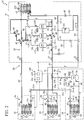
- these utilization side circuits (70, 80, 90) are connected in parallel to the outdoor circuit (40) thereby to constitute a refrigerant circuit (20) which performs a vapor compression refrigeration cycle.
- the outdoor circuit (40) and each utilization side circuit (70, 80, 90) are connected together by liquid side interunit piping (31), first gas side interunit piping (32), and second gas side interunit piping (33).
- One end of the liquid side interunit piping (31) is connected to a liquid side closing valve (21) of the outdoor circuit (40).
- the other end of the liquid side interunit piping (31) diverges into three branches, namely a first liquid branch pipe (31a), a second liquid branch pipe (31b), and a third liquid branch pipe (31c).
- the first to third liquid branch pipes (31a, 31b, 31c) are connected to the air conditioning circuit (70), to the cold-storage circuit (80), and to the freeze-storage circuit (90), respectively.
- first gas side interunit piping (32) is connected to a first gas side closing valve (22) of the outdoor circuit (40) and the other end thereof is connected to the air conditioning circuit (70).
- One end of the second gas side interunit piping (33) is connected to a second gas side closing valve (23) of the outdoor circuit (40).
- the other end of the second gas side interunit piping (33) diverges into two branches, namely a first gas branch pipe (33a) and a second gas branch pipe (33b).
- the first and second gas branch pipes (33a, 33b) are connected to the cold-storage circuit (80) and to the freeze-storage circuit (90), respectively.
- the outdoor circuit (40) of the outdoor unit (11) includes three (first to third) compressors (41, 42, 43), an outdoor heat exchanger (44), a receiver (45), an outdoor expansion valve (46), and three (first to third) four-way selector valves (47, 48, 49).
- the first to third compressors (41, 42, 43) are each formed by a respective scroll compressor of the high pressure dome type.
- the first compressor (41) constitutes a compressor of the variable capacity type. That is, the first compressor (41) is configured such that its speed of rotation is made variable by inverter control.
- the second and third compressors (42, 43) each constitute a compressor of the fixed capacity type, that is, whose speed of rotation is fixed.
- first intake pipe (51) Connected to the intake side of the first compressor (41) is one end of a first intake pipe (51). The other end of the first intake pipe (51) is connected to the second gas side closing valve (23). Connected to the intake side of the second compressor (42) is one end of a second intake pipe (52). The other end of the second intake pipe (52) is connected to the third four-way selector valve (49). Connected to the intake side of the third compressor (43) is one end of a third intake pipe (53). The other end of the third intake pipe (53) is connected to the second four-way selector valve (48).
- first delivery pipe Connected to the delivery side of the first compressor (41) is one end of a first delivery pipe (54). The other end of the first delivery pipe (54) is connected through delivery piping (57) to the first four-way selector valve (47). Connected to the delivery side of the second compressor (42) is one end of a second delivery pipe (55). The other end of the second delivery pipe (55) is connected to the delivery piping (57). Connected to the delivery side of the third compressor (43) is one end of a third delivery pipe (56). The other end of the third delivery pipe (56) is connected in the middle of the delivery piping (57).
- the outdoor heat exchanger (44) is a fin-and-tube heat exchanger of the cross fin type, and constitutes a heat source side heat exchanger. There is arranged in the vicinity of the outdoor heat exchanger (44) an outdoor fan (50). In the outdoor heat exchanger (44), the exchange of heat takes place between the outdoor air distributed by the outdoor fan (50) and the refrigerant.
- One end of the outdoor heat exchanger (44) is connected to the first four-way selector valve (47).
- the other end of the outdoor heat exchanger (44) is connected through a first liquid pipe (58) to the top of the receiver (45).
- the bottom of the receiver (45) is connected through a second liquid pipe (59) to the liquid side closing valve (21).
- first and second bypass pipes 60, 61
- first and second bypass pipes 60, 61
- the other ends of the first and second bypass pipes 60, 62
- the outdoor expansion valve (46) is disposed in the first bypass pipe (60).
- the outdoor expansion valve (46) is formed by an electronic expansion valve whose degree of opening is adjustable.
- One end of a liquid injection pipe (62) is connected in the middle of the second bypass pipe (61).
- the other end of the liquid injection pipe (62) is connected in the middle of the first intake pipe (51).
- the liquid injection pipe (62) is provided with a flow control valve (63) whose degree of opening is adjustable.
- Each of the first to third four-way selector valves (47, 48, 49) has four (first to fourth) ports.
- the first four-way selector valve (47) its ports are connected as follows: the first port is connected to the delivery piping (57); the second port is connected to the fourth port of the second four-way selector valve (48); the third port is connected to the outdoor heat exchanger (44); and the fourth port is connected to the first gas side closing valve (22).
- the second four-way selector valve (48) its ports are connected as follows: the first and second ports are connected to the third delivery pipe (56) and to the third intake pipe (53), respectively, while the third port is closed.
- the third four-way selector valve (49) its ports are connected as follows: the second to fourth ports are connected to the second intake pipe (52), to the third intake pipe (53), and to the first intake pipe (51), respectively, while the first port is closed.
- Each of the four-way selector valves (47, 48, 49) is selectively switchable between a first state (indicated by solid line in FIG. 1 ) and a second state (indicated by broken line in FIG. 1 ).
- first state indicated by solid line in FIG. 1
- second state indicated by broken line in FIG. 1
- first and third ports fluidly communicate with each other
- second and fourth ports fluidly communicate with each other.
- the first and fourth ports fluidly communicate with each other, while the second and third ports fluidly communicate with each other.
- the first intake pipe (51) is provided with a first intake temperature sensor (111) and a first intake pressure sensor (112).
- the third intake pipe (53) is provided with a second intake temperature sensor (113) and a second intake pressure sensor (114).
- the first delivery pipe (54) is provided with a first high pressure switch (115).
- the second delivery pipe (55) is provided with a second high pressure switch (116).
- the third delivery pipe (56) is provided with a third high pressure switch (117).
- the delivery piping (57) is provided with a first delivery temperature sensor (118) and a first delivery pressure sensor (119).
- the third delivery pipe (56) is provided with a second delivery temperature sensor (120).
- the outdoor heat exchanger (44) is provided, in its heat transfer tube, with an outdoor side refrigerant temperature sensor (121). In addition, there is disposed in the vicinity of the outdoor heat exchanger (44) an outdoor temperature sensor (122).
- the outdoor circuit (40) is provided with a plurality of check valves configured to allow refrigerant to flow in one direction only while stopping the flow of refrigerant in the opposite direction.
- a check valve (CV-1) is disposed in piping between the first intake pipe (51) and the second intake pipe (52).
- a check valve (CV-2) is disposed in piping between the second intake pipe (52) and the third intake pipe (53).
- the second delivery pipe (55) is provided with a check valve (CV-3).
- the third delivery pipe (56) is provided with a fourth check valve (CV-4).
- the first liquid pipe (58) is provided with a check valve (CV-5).
- the second liquid pipe (59) is provided with a check valve (CV-6).
- the second bypass pipe (61) is provided with a check valve (CV-7).
- the check valves (CV-1, CV-2, ...) are so configured as to permit only the flow of refrigerant in directions indicated by arrows assigned to the symbols representative of these valves in FIG. 1 .
- the air conditioning circuit (70) of the air conditioning unit (12) is provided with an indoor heat exchanger (71) and an indoor expansion valve (72).
- the indoor heat exchanger (71) is a fin-and-tube heat exchanger of the cross fin type, and constitutes a first utilization side heat exchanger.
- the indoor heat exchanger (71) constitutes a heating heat exchanger capable of a heating operation in which heat is released from the refrigerant.
- the indoor expansion valve (72) is formed by an electronic expansion valve whose degree of opening is adjustable by a pulse motor.
- a first refrigerant temperature sensor (123) is disposed in piping between the first gas side interunit piping (32) and the indoor heat exchanger (71) and a second refrigerant temperature sensor (124) is disposed in the heat transfer tube of the indoor heat exchanger (71).
- an indoor temperature sensor (125) is disposed in the vicinity of the indoor heat exchanger (71) in the vicinity of the indoor heat exchanger (71) in the vicinity of the indoor heat exchanger (71) in the vicinity of the indoor heat exchanger (71).
- the cold-storage circuit (80) of the cold-storage showcase (13) is provided with a cold-storage heat exchanger (81) and a cold-storage expansion valve (82).
- the cold-storage heat exchanger (81) is a fin-and-tube heat exchanger of the cross fin type, and constitutes a second utilization side heat exchanger.
- the cold-storage heat exchanger (81) is a refrigeration heat exchanger in which refrigerant absorbs heat from air for the provision of refrigeration to the cold-storage compartment.
- a cold-storage fan (83) There is disposed in the vicinity of the cold-storage heat exchanger (81) a cold-storage fan (83). In the cold-storage heat exchanger (81), the exchange of heat takes place between the storage compartment air distributed by the cold-storage fan (83) and the refrigerant.
- a first outlet refrigerant temperature sensor (126) is disposed on the outflow side of the cold-storage heat exchanger (81).
- the cold-storage expansion valve (82) is formed by an expansion valve of the temperature sensing type whose degree of opening can be adjusted depending on the temperature detected by the first outlet refrigerant temperature sensor (126).
- SV-1 first solenoid valve
- a first storage compartment temperature sensor (127) for the detection of the temperature of storage compartment air in the cold-storage showcase (13).
- the freeze-storage circuit (90) of the freeze-storage showcase (14) is provided with a freeze-storage heat exchanger (91), a freeze-storage expansion valve (92), and a booster compressor (94).
- the freeze-storage heat exchanger (91) is a fin-and-tube heat exchanger of the cross fin type, and constitutes a third utilization side heat exchanger.
- the freeze-storage heat exchanger (91) is a refrigeration heat exchanger in which refrigerant absorbs heat from air for the provision of refrigeration to the freeze-storage compartment.
- a freeze-storage fan (93) There is disposed in the vicinity of the freeze-storage heat exchanger (91) a freeze-storage fan (93). In the freeze-storage heat exchanger (91), the exchange of heat takes place between the storage compartment air distributed by the freeze-storage fan (93) and the refrigerant.
- a second outlet refrigerant temperature sensor (128) is disposed on the outflow side of the freeze-storage heat exchanger (91).
- the freeze-storage expansion valve (92) is formed by an expansion valve of the temperature sensing type whose degree of opening can be adjusted depending on the temperature detected by the second outlet refrigerant temperature sensor (128).
- SV-2 second solenoid valve
- the booster compressor (94) is a scroll compressor of the high pressure dome type, and constitutes a compressor of the variable capacity type.
- a fourth intake pipe (95) and a fourth deliver pipe (96) are connected to the intake side and to the delivery side of the booster compressor (94), respectively.
- the fourth delivery pipe (96) is provided with a fourth high pressure switch (130), an oil separator (97), and a check valve (CV-8).
- Connected to the oil separator (97) is an oil return pipe (98) for the return of refrigeration oil separated from the refrigerant, to the intake side of the booster compressor (94).
- the oil return pipe (98) is provided with a capillary tube (98a).
- the freeze-storage circuit (90) is provided also with a third bypass pipe (99) by which the fourth intake pipe (95) and the fourth delivery pipe (96) are connected together.
- the third bypass pipe (99) is provided with a check valve (CV-9).
- the third bypass pipe (99) is configured such that, for example, when the booster compressor (94) breaks down, the refrigerant flowing in the fourth intake pipe (95) is made to bypass the booster compressor (94) and be fed to the fourth delivery pipe (96).
- the refrigeration system (10) is provided with a controller (100) for controlling the devices (targets for control) disposed in the refrigerant circuit (20).
- the controller (100) is configured such that it can receive signals from the sensors disposed in the refrigerant circuit (20). And in response to the signals from the sensors, the controller (100) controls the operation of each compressor, the switching of each four-way selector valve and other operations.
- the controller (100) is provided with a degree-of-opening control means (101) and an operation control means (102) both of which are features of the present invention.
- the degree-of-opening control means (101) and the operation control means (102) together constitute a means for preventing the accumulation of refrigerant in the indoor heat exchanger (71) when the heating operation of the indoor heat exchanger (71) is stopped.
- the operation of control by the degree-of-opening control means (101) and the operation of control by the operation control means (102) will fully be described hereinafter.
- the following is a description of the running operation of the refrigeration system (10) according to the present embodiment.
- the refrigeration system (10) it is possible to selectively perform a space cooling operation in which the air conditioning unit (12) provides indoor space cooling while simultaneously the storage compartment of each showcase (13, 14) is being refrigerated, or a space heating operation in which the air conditioning unit (12) provides indoor space heating while simultaneously the storage compartment of each showcase (13, 14) is being refrigerated.
- FIG. 2 a typical space cooling operation of the refrigeration system (10) will be described below.
- the first four-way selector valve (47), the second four-way selector valve (48), and the third four-way selector valve (49) are all placed in the first state.
- the outdoor expansion valve (46) and the flow control valve (63) are fully closed and the first and second solenoid valves (SV-1, SV-2) are opened.
- the indoor expansion valve (72), the cold-storage expansion valve (82), and the freeze-storage expansion valve (92) are properly adjusted in their degree of opening.
- the fans (50, 73, 83, 93), the first to third compressors (41, 42, 43), and the booster compressor (94) are each placed in operation.
- the refrigerant admitted to the first liquid branch pipe (31a) is pressure reduced during its passage through the indoor expansion valve (72), and then flows through the indoor heat exchanger (71).
- the indoor heat exchanger (71) the refrigerant absorbs heat from the indoor air and evaporates.
- indoor space cooling is provided.
- the refrigerant evaporated in the indoor heat exchanger (71) flows sequently through the first gas side interunit piping (32), then through the first four-way selector valve (47), then through the second four-way selector valve (48), and then through the third intake pipe (53), and is drawn into the third compressor (43).
- the refrigerant admitted to the second liquid branch pipe (31b) is pressure reduced during its passage through the cold-storage expansion valve (82), and then flows through the cold-storage heat exchanger (81).
- the cold-storage heat exchanger (81) the refrigerant absorbs heat from the storage compartment air and evaporates.
- the storage compartment of the cold-storage showcase (13) is refrigerated.
- the storage compartment temperature is maintained at, for example, 5 degrees Centigrade.
- the refrigerant evaporated in the cold-storage heat exchanger (81) flows into the first gas branch pipe (33a).
- the refrigerant admitted to the third liquid branch pipe (31c) is pressure reduced during its passage through the freeze-storage expansion valve (92), and then flows through the freeze-storage heat exchanger (91).
- the freeze-storage heat exchanger (91) the refrigerant absorbs heat from the storage compartment air and evaporates.
- the storage compartment of the freeze-storage showcase (14) is refrigerated.
- the storage compartment temperature is maintained at, for example, minus 10 degrees Centigrade.
- the refrigerant evaporated in the freeze-storage heat exchanger (91) is compressed in the booster compressor (94), and then flows into the second gas branch pipe (33b).
- the joined flow of refrigerant in the second gas side interunit piping (33) diverges again into the first and second intake pipes (51, 52), the refrigerant diverged into the former of which is drawn into the first compressor (41) and the refrigerant diverged into the latter of which is drawn into the second compressor (42).
- the first four-way selector valve (47) and the second four-way selector valve (48) are placed in the second state, while the third four-way selector valve (49) is placed in the first state.
- the outdoor expansion valve (46) and the flow control valve (63) are fully closed, while the first and second solenoid valves (SV-1, SV-2) are opened.
- the indoor expansion valve (72), the cold-storage expansion valve (82), and the freeze-storage expansion valve (92) are properly adjusted in their degree of opening.
- the fans (50, 73, 83, 93), the first and second compressors (41, 42), and the booster compressor (94) are all placed in operation.
- One refrigerant flow passes through the second four-way selector valve (48) and flows through the outdoor heat exchanger (44) where it condenses. Thereafter, the condensed refrigerant flows, through the first liquid pipe (58), then through the receiver (45), and then through the second liquid pipe (59) in that order, into the liquid side interunit piping (31). Meanwhile, the other refrigerant flow passes through the first four-way selector valve (47) and then flows through the indoor heat exchanger (71).
- the refrigerant dissipates heat to the indoor air and condenses. As a result, indoor space heating is provided.
- the refrigerant condensed in the indoor heat exchanger (71) is pressure reduced during its passage through the indoor expansion valve (72), and then flows into the first liquid branch pipe (31a).
- the joined flow of refrigerant in the liquid side interunit piping (31) again diverges in two branches, namely the second liquid branch pipe (31b) and the third liquid branch pipe (31c).
- the refrigerant admitted to the second liquid branch pipe (31b) is used to provide refrigeration of the storage compartment of the cold-storage showcase (13), as in the foregoing space cooling operation.
- the refrigerant admitted to the third liquid branch pipe (31c) is used to provide refrigeration of the storage compartment of the freeze-storage showcase (14), as in the foregoing space cooling operation.
- the flows of refrigerant used to provide refrigeration of the showcases (13, 14) join together in the second gas side interunit piping (33).
- the joined flow of refrigerant is drawn into the first and second compressors (41, 42).
- the heating operation by the indoor heat exchanger (71) may no longer be required in some cases, for example, when the room temperature reaches a user preset temperature. Therefore, in the refrigeration system (10), there is carried out a first control operation (thermo-off operation) to temporarily place the indoor heat exchanger (71) in the out-of-operation state if a given condition holds in the foregoing space heating operation.
- a first control operation thermo-off operation
- the degree-of-opening control means (101) of the controller (100) provides control of the degree of opening of the indoor expansion valve (72) so that the indoor expansion valve (72) is fully closed.
- most of the refrigerant delivered out from both the first compressor (41) and the second compressor (42) is fed towards the outdoor heat exchanger (44), as shown in FIG. 5 .
- the refrigerant after condensation in the outdoor heat exchanger (44) is fed, through the same distribution route as in the aforesaid space heating operation, to each showcase (13, 14) where it is used to provide refrigeration of the storage compartment.
- the indoor expansion valve (72) enters the fully closed state and no refrigerant will flow through the indoor heat exchanger (71). Consequently, in the indoor heat exchanger (71), there is no active exchange of heat between the refrigerant and the indoor air and, as a result, the indoor heat exchanger (71) is substantially placed in the out-of-operation state (thermo-off state). Thereafter, if a given condition holds (for example, if the room temperature falls lower than a preset temperature level by more than a predetermined value), this places the indoor heat exchanger (71) in the thermo-off state and the foregoing space heating operation resumes.
- the indoor expansion valve (72) enters the fully closed state as described above.
- the gas side of the indoor heat exchanger (71) still remains in fluid communication with the refrigerant circulation path. Therefore, after the thermo-off operation, refrigerant flows into the indoor heat exchanger (71) and gradually condenses to liquid form and this liquid refrigerant after condensation will accumulate in gradual degrees within the indoor heat exchanger (71). That is, in the indoor heat exchanger (71) in the thermo-off state, there is the possibility that the so-called "refrigerant's falling-asleep" may occur.
- the degree-of-opening control means (101) of the present embodiment first provides control so that the indoor expansion valve (72) is placed in the fully closed state when thermo-offing the air conditioning unit (12) and, then, a degree-of-opening control operation (i.e., the second control operation) is performed to properly adjust the degree of opening of the indoor expansion valve (72), whereby the elimination of "refrigerant's falling-asleep" within the indoor heat exchanger (71) can be accomplished.
- a degree-of-opening control operation i.e., the second control operation
- Step S1 a determination is made as to whether or not the accumulated amount of refrigerant within the indoor heat exchanger (71) is great. More specifically, in Step S1, the pressure difference, (Pc - Th1), between Pc (the saturated temperature corresponding to the high pressure found from the values detected by the first delivery temperature sensor (118) and the first delivery pressure sensor (119)) and Th1 (the refrigerant temperature detected by the first refrigerant temperature sensor (123)), is calculated. To sum up, in Step S1, the degree of refrigerant subcooling, (Pc - Th1), in the vicinity of the inlet of the indoor heat exchanger (71) is calculated.
- the degree of subcooling, (Pc - Th1), of such refrigerant serves as an index indicative of the amount of refrigerant within the indoor heat exchanger (71).
- Step S1 makes a determination that the accumulated amount of refrigerant within the indoor heat exchanger (71) is great, and the control procedure moves to Step S2.
- the current degree of opening of the indoor expansion valve (72) is increased by an amount corresponding to a predetermined number of pulses (for example, 352 pulses).
- the refrigerant accumulated within the indoor heat exchanger (71) is passed through the indoor expansion valve (72), flows through the first liquid branch pipe (31a), and is fed into each showcase (13, 14).
- Step S3 it makes a determination as to whether or not the elimination of "refrigerant's falling-asleep" within the indoor heat exchanger (71) is accomplished.
- Step S3 makes a determination that very little refrigerant has accumulated within the indoor heat exchanger (71), and the control procedure moves to Step S4. As a result, the indoor expansion valve (72) enters the fully closed state.
- Step S3 the temperature difference, (Pc - Th2), between Pc (the saturated temperature corresponding to the high pressure and Th2 (the refrigerant temperature, detected by the second refrigerant temperature sensor (124)) is calculated. That is, in Step S3, the degree of refrigerant subcooling, (Pc - Th2), immediately before the outlet of the indoor heat exchanger (71) is also calculated. And if the degree of subcooling, (Pc - Th2), continues to fall below T2 degrees Centigrade (for example, 5 degrees Centigrade) for longer than t2 minutes (for example, 2 minutes), this makes a determination that very little liquid refrigerant has accumulated within the indoor heat exchanger (71), and the control procedure moves to Step S4.
- T2 degrees Centigrade for example, 5 degrees Centigrade
- t2 minutes for example, 2 minutes
- Step S1 or Step S3 the indoor expansion valve (72) will remain in the fully closed state because the value of the degree of refrigerant subcooling becomes small although the accumulated amount of refrigerant within the indoor heat exchanger (71) is great.
- Step S5 makes a determination that the indoor expansion valve (72) continues to remain in the fully closed state for longer than t3 minutes (for example, 20 minutes), then the control procedure moves to Step S6 on the assumption that there is the possibility that the amount of refrigerant within the indoor heat exchanger (71) may not have been detected accurately.
- Step S6 the degree of opening of the indoor expansion valve (72) is opened at a predetermined degree of opening (for example, 352 pulses). As a result, if there is an accumulation of refrigerant within the indoor heat exchanger (71), the refrigerant accumulated will be expelled promptly to outside the indoor heat exchanger (71).
- Step S1 or Step S3 this facilitates the accurate detection of the amount of refrigerant within the indoor heat exchanger (71) when making a determination in Step S1 or Step S3. That is, after the completion of Step S6, the continuous supply of refrigerant to the indoor heat exchanger (71) is made. As a result, the refrigerant flowing in the indoor heat exchanger (71) is less subject to the influence of the ambient temperature. Consequently, it is avoided that the value of the degree of refrigerant subcooling will become small due to the influence of the ambient temperature. Hence, when making a determination in the following steps (Steps S1, S3), it becomes possible to control the degree of opening of the indoor expansion valve (72) by accurate detection of the amount of refrigerant within the indoor heat exchanger (71).
- each of Steps S1-S6 is repeatedly carried out so that the degree of opening of the indoor expansion valve (72) can be properly adjusted depending on the accumulated amount of refrigerant within the indoor heat exchanger (71) in the thermo-off state.
- the elimination of "refrigerant's falling-asleep" within the indoor heat exchanger (71) is accomplished, whereby it is avoided that the cold-storage heat exchanger (81) and the freeze-storage heat exchanger (91) will deteriorate in their refrigeration capacity.
- the head difference of the interunit piping (the first gas side interunit piping (32)) extending from the outdoor unit (11) to the air conditioning unit (12) is great because the air conditioning unit (12) is installed relatively higher than the outdoor unit (11) of the refrigeration system (10)
- the refrigerant accumulated within the indoor heat exchanger (71) will not be sufficiently expelled outside because the refrigerant delivered out from each compressor (41, 42) is supplied only to the outdoor heat exchanger (44) even when the degree of opening of the indoor expansion valve (72) is placed in the fully opened state (for example, 2000 pulses) by the degree-of-opening control operation.
- the operation control means (102) of the controller (100) provides the following control.
- Step S11 makes a determination as to whether or not the elimination of "refrigerant's falling-asleep" within the indoor heat exchanger (71) still remains unaccomplished. More specifically, if the degree of refrigerant subcooling, (Pc - Th1), on the inlet side of the indoor heat exchanger (71) continues to remain greater than T1 degrees Centigrade for longer than t4 minutes (for example 20 minutes), then Step S11 makes a determination that the elimination of "refrigerant's falling-asleep" within the indoor heat exchanger (71) has not yet been accomplished, and the control procedure moves to Step S12. As a result, in the refrigeration system (10), the following heat recovery operation is carried out.
- Pc - Th1 degree of refrigerant subcooling
- the first four-way selector valve (47) is placed in the second state and the second and third four-way selector valves (48, 49) are placed in the first state.
- the outdoor expansion valve (46) and the flow control valve (63) are fully closed, while the first and second solenoid valves (SV-1, SV-2) are opened.
- the indoor expansion valve (72), the cold-storage expansion valve (82), and the freeze-storage expansion valve (92)) are properly adjusted in their degree of opening.
- the fans (50, 73, 83, 93), the first and second compressors (41, 42), and the booster compressor (94) are all placed in operation.
- the joined flow of refrigerant passes through the first four-way selector valve (47) and then flows through the indoor heat exchanger (71).
- the indoor heat exchanger (71) the refrigerant accumulated therein is forced out by the high pressure refrigerant and expelled outside the indoor heat exchanger (71).
- the heating operation is temporarily carried out in the indoor heat exchanger (71).
- the refrigerant leaving the indoor heat exchanger (71) is pressure reduced during its passage through the indoor expansion valve (72) and then admitted to the first liquid branch pipe (31a).
- the refrigerant admitted to the first liquid branch pipe (31a) diverges into two branches, namely the second liquid branch pipe (31b) and the third liquid branch pipe (31c).
- the refrigerant admitted to the second liquid branch pipe (31b) is used to provide refrigeration of the storage compartment of the cold-storage showcase (13).
- the refrigerant admitted to the third liquid branch pipe (31c) is used to provide refrigeration of the storage compartment of the freeze-storage showcase (14).
- the flows of refrigerant used for the refrigeration of the showcases (13, 14) join together in the second gas side interunit piping (33). Thereafter, the joined flow of refrigerant is drawn into the first and second compressors (41, 42).
- the heat recovery operation differs from the aforesaid space heating operation in that the refrigerant delivered from the first and second compressors (41, 42) is supplied only towards the air conditioning unit (12). Consequently, even in the installation situation where the head difference between the outdoor unit (11) and the air conditioning unit (12) is great, it is ensured that the supply of high pressure refrigerant to the air conditioning unit (12) is provided without fail. As a result, the refrigerant accumulated within the indoor heat exchanger (71) is expelled outside without fail and is used to provide refrigeration of each showcase (13, 14).
- Step S13 makes a determination as to whether or not the elimination of "refrigerant's falling-asleep" within the indoor heat exchanger (71) is accomplished. More specifically, if the degree of refrigerant subcooling within the indoor heat exchanger (71), (Pc - Th2), continues to remain less than T2 degrees Centigrade for longer than t5 minutes (for example, 2 minutes), Step S13 makes a determination that the elimination of "refrigerant's falling-asleep" is accomplished, and the control procedure moves to Step S14.
- Step S14 the heat recovery operation is brought to a stop and the indoor heat exchanger (71) again enters the thermo-off state.
- Step S14 makes a determination that the elimination of "refrigerant's falling-asleep" is accomplished without fail, and the control procedure moves to Step S14.
- the degree-of-opening control operation in which the degree of opening of the indoor expansion valve (72) is adjusted based on the index (the degree of refrigerant subcooling) indicative of the accumulated amount of refrigerant within the indoor heat exchanger (71), is carried out.
- the degree-of-opening control operation as the accumulated amount of refrigerant within the indoor heat exchanger (71) increases, the degree of opening of the indoor expansion valve (72) is increased.
- the refrigerant accumulated within the indoor heat exchanger (71) is properly expelled outside for forwarding to the cold-storage showcase (13) and to the freeze-storage showcase (14). Accordingly, it is ensured that the elimination of "refrigerant's falling-asleep" within the indoor heat exchanger (71) can be accomplished without fail, whereby it becomes possible to prevent the deterioration of refrigeration capacity in the storage compartment of each showcase (13, 14).
- the degree of opening of the expansion valve (72) is reduced if the accumulated amount of refrigerant within the indoor heat exchanger (71) is small. Consequently, in accordance with the aforesaid embodiment, it can be avoided that the excess supply of refrigerant is provided to the indoor heat exchanger (71) despite the fact that the elimination of "refrigerant's falling-asleep" within the indoor heat exchanger (71) has already been accomplished, thereby making it possible that the supply of refrigerant to be provided to each showcase (13, 14) is satisfactorily secured. Accordingly, it becomes possible to more effectively prevent the capacity of refrigeration of the storage compartment of each showcase (13, 14) from deterioration.
- the accumulated amount of refrigerant within the indoor heat exchanger (71) is detected with the aid of the degree of refrigerant subcooling on the inlet side of or within the indoor heat exchanger (71). Consequently, in accordance with the foregoing embodiment, it is possible to relatively easily observe the occurrence of the "refrigerant's falling-asleep" within the indoor heat exchanger (71).
- the indoor expansion valve (72) is opened if the indoor expansion valve (72) continues to remain in the fully closed state for longer than a predetermined length of time, in view of the fact that the degree of refrigerant subcooling decreases due to the influence of the ambient temperature of the indoor heat exchanger (71). Consequently, in accordance with the foregoing embodiment, it can be avoided that the indoor expansion valve (72) enters the state of remaining closed despite that fact that the "refrigerant's falling-asleep" is in fact occurring in the indoor heat exchanger (71). This makes it sure that the elimination of "refrigerant's falling-asleep" within the indoor heat exchanger (71) is accomplished without fail.
- the degree of refrigerant subcooling is less subject to the influence of the ambient temperature of the indoor heat exchanger (71) in the subsequent degree-of-opening control operation, whereby the amount of refrigerant within the indoor heat exchanger (71) can be detected with accuracy. Consequently, in accordance with the present embodiment, it is possible to properly control the degree of opening of the expansion valve (72) depending on the accumulated amount of refrigerant within the indoor heat exchanger (71). This therefore makes it sure that the elimination of "refrigerant's falling-asleep" within the indoor heat exchanger (71) can be accomplished without fail and, in addition, the sufficient supply of refrigerant to each showcase (13, 14) can be secured.
- the heat recovery operation is carried out in the refrigerant circuit (20) if the elimination of "refrigerant's falling-asleep" within the indoor heat exchanger (71) still remains unaccomplished even when the degree-of-opening control operation is performed by the degree-of-opening control means (101) after the execution of the thermo-off operation of the indoor heat exchanger (71).
- the total amount of refrigerant delivered out from each compressor (41, 42) is fed towards the indoor heat exchanger (71).
- the foregoing embodiment may be configured as follows.
- the number of air conditioning units (12) connected to the outdoor unit (11) is one.
- a plurality of air conditioning units of such a type may be connected to the outdoor unit (11).
- the elimination of "refrigerant's falling-asleep" in each indoor heat exchanger can be accomplished by the execution of the foregoing degree-of-opening control operation after the thermo-offing of the indoor heat exchanger of each air conditioning unit.
- the fully closing of the indoor expansion valve (72) is carried out as the thermo-off operation of the indoor heat exchanger (71).
- the degree of opening of the indoor expansion valve (72) may be reduced to a very small degree of opening.
- the accumulation of refrigerant will gradually proceed within the indoor heat exchanger (71).
- the foregoing degree-of-opening control operation is carried out to eliminate the "refrigerant's falling-asleep".
- the accumulated amount of refrigerant within the indoor heat exchanger (71) in the thermo-off state is found from the degree of refrigerant subcooling on the inflow side of or within the indoor heat exchanger (71).
- the accumulated amount of refrigerant within the indoor heat exchanger (71) may be found by other than the above method.
- the present invention finds its utility in the prevention of "refrigerant's falling-asleep" in a heating heat exchanger placed in the out-of-operation state in a refrigeration system having a plurality of utilization units.
Landscapes
- Engineering & Computer Science (AREA)
- Mechanical Engineering (AREA)
- General Engineering & Computer Science (AREA)
- Combustion & Propulsion (AREA)
- Physics & Mathematics (AREA)
- Chemical & Material Sciences (AREA)
- Thermal Sciences (AREA)
- Signal Processing (AREA)
- Life Sciences & Earth Sciences (AREA)
- Sustainable Development (AREA)
- Fuzzy Systems (AREA)
- Mathematical Physics (AREA)
- Air Conditioning Control Device (AREA)
- Compression-Type Refrigeration Machines With Reversible Cycles (AREA)
- Devices That Are Associated With Refrigeration Equipment (AREA)
Description
- This invention generally relates to a refrigeration system having a plurality of utilization side units and more particularly to the prevention of the accumulation of refrigerant ("refrigerant's falling-asleep" in the industry jargon) in a heating heat exchanger placed out of operation.
- In
JP H07 158989 A JP H07 158989 A claim 1. InJP 2003 056933 A - In
JP H08 178447 - Further, in the past, various refrigeration systems that perform a refrigeration cycle by the circulation of refrigerant have widely been applied to air conditioning systems and other like systems. There is known, as such a type of refrigeration system, a so-called multi-type refrigeration system in which a plurality of utilization side units is connected in parallel to a heat source side unit.
- For example,
JP-A-1996-159590 - In the refrigeration system of the patent document, each expansion valve is opened at a predetermined degree of opening, thereby making it possible for each utilization side heat exchanger to individually carry out a space heating operation. More specifically, for example, in the case where these two utilization side units perform respective space heating operations at the same time, both the expansion valves are placed in the opened state so that refrigerant is fed to both the utilization side heat exchangers. As a result, heat is released from the refrigerant flowing through each utilization side heat exchanger to the indoor air and each utilization side heat exchanger performs a heating operation. As a result, indoor spaces respectively corresponding to the utilization side heat exchangers are heated. On the other hand, for example, in the case where space heating is carried out by one of the utilization side units, it is arranged such that the expansion valve associated with the one utilization side unit to be placed in operation is opened while the expansion valve associated with the other utilization side unit to be placed out of operation is closed. As a result of such arrangement, refrigerant is fed only to the utilization side unit in operation and only this utilization side heat exchanger provides indoor space heating.
- Incidentally, if, as described above, one of the expansion valves is closed in order to place its associated utilization side unit in the out-of-operation state (the so-called thermo-off state), this causes the possibility that there will occur a phenomenon (known in the art as a phenomenon of "refrigerant's falling-asleep"). More specifically, in such a phenomenon, refrigerant condenses in the utilization side heat exchanger placed in the out-of-operation state, resulting in the accumulation of condensed liquid refrigerant therein. And if, as described above, the refrigerant accumulates in large amounts within one of the utilization side heat exchangers, the supply of refrigerant to the other utilization side unit becomes scant. This gives rise to the problem that the other utilization side unit degrades in refrigeration capacity or heating capacity.
- In view of the above problems with the prior art, the present invention was made. Accordingly, an object of the present invention is to ensure the prevention of any accumulation ("falling-asleep") of refrigerant within a utilization side heat exchanger placed in the out-of-operation state.
- The problem is solved by a refrigeration system according to
claim 1. The present invention provides a refrigeration system including a refrigerant circuit, the refrigerant circuit being configured such that a plurality of utilization side units (12, 13, 14) are connected in parallel to a heat source side unit (11) having a compressor (41, 42) and a heat source side heat exchanger (44), wherein at least one of the plurality of utilization side units (12, 13, 14) includes a heating heat exchanger (71) configured to perform a heating operation in which heat is released from refrigerant and an expansion valve (72) associated with the heating heat exchanger. And the refrigeration system includes a degree-of-opening control means (101) configured to perform: (a) when placing the heating heat exchanger (71) in the out-of-operation state, a first control operation of reducing the degree of opening of the expansion valve (72) to such an extent that the expansion valve (72) is either fully closed or very slightly opened; and (b) after the completion of the first control operation, a second control operation of adjusting the degree of opening of the expansion valve (72). based on an index indicative of the accumulated amount of refrigerant within the heating heat exchanger (71). - In the present invention, the plurality of utilization side units (12, 13, 14) are connected in parallel to the heat source side unit (11). This arrangement constitutes a so-called multi-type refrigeration system. In the refrigerant circuit (20) of the refrigeration system, a vapor compression refrigeration cycle is performed by the circulation of refrigerant. Refrigerant is supplied to each of the utilization side units (12, 13, 14) where it evaporates or condenses, and by these utilization side units (12, 13, 14), indoor space heating/cooling or showcase storage compartment refrigeration is separately provided.
- Here, in the present invention, when stopping the heating heat exchanger (71) configured to perform a heating operation in which heat is released from the refrigerant, the degree-of-opening control means (101) first performs a first control operation. In the first control operation, the degree of opening of the expansion valve (72) associated with the heating heat exchanger (71) is reduced to the fully closed degree or to an extremely small degree as close to the fully closed degree as possible. As a result, since almost no refrigerant is fed to the heating heat exchanger (71), no heating operation is carried out in the heating heat exchanger (71). On the other hand, if the expansion valve (72) is throttled in such a manner, this causes the refrigerant within the heating heat exchanger (71) to gradually condense, as a result of which liquid refrigerant will accumulate within the heating heat exchanger (71). This results in the occurrence of "refrigerant's falling-asleep" in the heating heat exchanger (71).
- To cope with the above, after the completion of the first control operation, the degree-of-opening control means (101) of the present invention carries out a second control operation in order to prevent the occurrence of "refrigerant's falling-asleep" in the heating heat exchanger (71). In the second control operation, the index indicative of the accumulated amount of refrigerant within the heating heat exchanger (71) is detected by means of a given method. And based on the index detected, the degree of opening of the expansion valve (72) is adequately adjusted. More specifically, if condensed refrigerant keeps accumulating within the heating heat exchanger (71) after the completion of the first control operation and, as a result, the index indicative of the accumulated amount of refrigerant within the heating heat exchanger (71) increases, then the degree-of-opening control means (101) provides control so that the degree of opening of the expansion valve (72) is increased. As a result, the refrigerant accumulated within the heating heat exchanger (71) is expelled through the expansion valve (72) to outside the utilization side unit (12).
- Meanwhile, if, after accomplishing the elimination of "refrigerant's falling-asleep" in the heating heat exchanger (71) in the way as described above, the degree of opening of the expansion valve (72) still remains in the largely opened state, this means that the supply of refrigerant to the heating heat exchanger (71) is provided in vain. As a result, the other utilization side unit (12) is likely to provide poor refrigeration (heating) capacity. To cope with this, in the second control operation, if the elimination of "refrigerant's falling-asleep" in the heating heat exchanger (71) is accomplished and, as a result, the aforesaid index decreases, then the degree of opening of the expansion valve (72) is promptly reduced with the aid of the degree-of-opening control means (101). As a result, the supply of refrigerant to the heating heat exchanger (71) decreases, whereby the supply of refrigerant to each of the other utilization side units (13, 14) increases accordingly.
- The present invention provides a refrigeration system that is characterized in that the utilization side units (13, 14) other than the at least one utilization side unit (12) that is provided with the heating heat exchanger (71) each include a respective refrigeration heat exchanger (81, 91) capable of a refrigeration operation in which refrigerant absorbs heat from air; that the refrigerant circuit (20) is configured to perform a heat recovery operation in which refrigerant delivered out from the compressor dissipates heat in the heating heat exchanger (71), absorbs heat in the refrigeration heat exchanger (81, 91), and then is drawn into the compressor (41, 42); and that there is provided an operation control means (102) configured to control the heat recovery operation such that it is temporarily carried out if, in the second control operation of the degree-of-opening control means (101), the index indicative of the accumulated amount of refrigerant within the heating heat exchanger (71) continues to be in excess of a specified value for longer than a predetermined length of time.
- In the present invention, the refrigeration heat exchangers (81, 91) are disposed respectively in the utilization side units (13, 14) other than the at least one utilization side unit (12) that is provided with the heating heat exchanger (71). In each refrigeration heat exchanger (81, 91), the refrigerant absorbs heat from air thereby to provide storage-compartment space refrigeration. In the refrigerant circuit (20) of the refrigeration system, it is possible to perform a heat recovery operation by the feeding of refrigerant delivered out from the compressor (41, 42) to the heating heat exchanger (71) and the refrigeration heat exchangers (81, 91) in that order and then by the returning of refrigerant to the intake side of the compressor (41, 42). That is, in the heat recovery operation, there is performed a refrigeration cycle in which refrigerant delivered out from the compressor (41, 42) is not fed to the heat source side heat exchanger (44) of the heat source side unit (11) but is condensed in the heating heat exchanger (71) while the refrigerant after condensation is pressure reduced in the expansion valve (72) and then is evaporated in the refrigeration heat exchanger (81, 82).
- Here, if the elimination of "refrigerant's falling-asleep" within the heating heat exchanger (71) fails to be accomplished even after the execution of the second control operation by the degree-of-opening control means (101), the operation control means (102) provides control so that the heat recovery operation is forcibly carried out in the refrigerant circuit (20). This causes the positive supply of refrigerant to the heating heat exchanger (71), thereby ensuring that the elimination of "refrigerant's falling-asleep" within the heating heat exchanger is accomplished. At the same time, the refrigerant discharged from within the heating heat exchanger (71) and flowing through the refrigeration heat exchanger (81, 82) is used for the refrigeration operation of the refrigeration heat exchanger (81, 82).
- In the present invention, when carrying out an operation to stop the heating heat exchanger (71), the degree of opening of the expansion valve (72) is reduced by a first control operation, which is followed by the execution of a second control operation to adjust the degree of opening of the expansion valve (72) based on the index indicative of the accumulated amount of refrigerant within the heating heat exchanger (71). Therefore, in accordance with the present invention, it becomes possible that, upon the detection of the occurrence of "refrigerant's falling-asleep" within the heating heat exchanger (71), the degree of opening of the expansion valve (72) is increased, whereby the refrigerant accumulated within the heating heat exchanger (71) can be fed to the other utilization side units (13, 14). That is, in accordance with the present invention, it is ensured that the elimination of "refrigerant's falling-asleep" within the heating heat exchanger (71) in the out-of-operation state is accomplished without fail, thereby making it possible to prevent the other utilization side units (13, 14) from capacity degradation.
- In addition, in accordance with the present invention, the degree of opening of the expansion valve (72) can be made small if the accumulated amount of refrigerant within the heating heat exchanger (71) is small. Therefore, it is avoided that an excess supply of refrigerant is provided to the heating heat exchanger (71) despite the fact that the elimination of "refrigerant's falling-asleep" within the heating heat exchanger (71) has already been accomplished. This makes it possible to satisfactorily ensure the supply of refrigerant to the other utilization side units (13, 14). Accordingly, it becomes possible to still further effectively prevent the other utilization side units (13, 14) from capacity degradation.
- In the present invention, the heat recovery operation is carried out in the refrigerant circuit (20) if the elimination of "refrigerant's falling-asleep" within the heating heat exchanger (71) still remains unaccomplished even after the execution of the second control operation by the degree-of-opening control means (101). Therefore, in accordance with the present invention, the elimination of "refrigerant's falling-asleep" within the heating heat exchanger (71) can be accomplished by the feed-in of refrigerant to the heating heat exchanger (71). At this time, in the present invention, the refrigerant delivered out from the compressor (41, 42) will not be fed into the heat source side heat exchanger (44) and others, but will be positively fed into the heating heat exchanger (71). Therefore, in accordance with the present invention, it is ensured that the refrigerant within the heating heat exchanger (71) is expelled outside.
- In addition, in the heat recovery operation, refrigerant is evaporated in each of the refrigeration heat exchangers (81, 91) while the accumulated refrigerant within the heating heat exchanger (71) is being expelled outside. That is, the present invention ensures that the elimination of "refrigerant's falling-asleep" within the heating heat exchanger (71) can be accomplished without the stop of the refrigeration operation by each of the refrigeration heat exchangers (81, 91).
- In the drawings:
-
FIG. 1 is a plumbing diagram of a refrigerant circuit in a refrigeration system according to an embodiment of the present invention; -
FIG. 2 is a plumbing diagram illustrating the flow of refrigerant during the space cooling operation; -
FIG. 3 is a plumbing diagram illustrating the flow of refrigerant during the space heating operation; -
FIG. 4 is a plumbing diagram illustrating the flow of refrigerant immediately after the thermo-off operation of an indoor heat exchanger; -
FIG. 5 is a flowchart illustrating a second control operation by a degree-of-opening control means; -
FIG. 6 is a flowchart illustrating the operation of control by an operation control means; and -
FIG. 7 is a plumbing diagram illustrating the flow of refrigerant during the heat recovery operation. - In the drawings:
- 10
- refrigeration system
- 12
- air conditioning unit (utilization side unit)
- 13
- cold-storage showcase (utilization side unit)
- 14
- freeze-storage showcase (utilization side unit)
- 20
- refrigerant circuit
- 41
- first compressor
- 42
- second compressor
- 71
- indoor heat exchanger (heating heat exchanger)
- 72
- indoor expansion valve (expansion valve)
- 81
- cold-storage heat exchanger (refrigeration heat exchanger)
- 91
- freeze-storage heat exchanger (refrigeration heat exchanger)
- 101
- degree-of-opening control means
- 102
- operation control means
- Hereinafter, with reference to the accompanying drawings, preferred embodiments of the present invention will be described in detail.
- A refrigeration system (10) according to the present embodiment is of the type for the installation in a convenience store or other facility. The refrigeration system (10) provides, at the same time, refrigeration to a cold-storage compartment and a freeze-storage compartment and air conditioning to an indoor space.
- As shown in
FIG. 1 , the refrigeration system (10) includes an outdoor unit (11), an air conditioning unit (12), a cold-storage showcase (13), and a freeze-storage showcase (14). The outdoor unit (11) is provided with an outdoor circuit (40) which constitutes a heat source side circuit. The air conditioning unit (12) is provided with an air conditioning circuit (70) which constitutes a first utilization side circuit. The cold-storage showcase (13) is provided with a cold-storage circuit (80) which constitutes a second utilization side circuit. The freeze-storage showcase (14) is provided with a freeze-storage circuit (90) which constitutes a third utilization side circuit. In the refrigeration system (1), these utilization side circuits (70, 80, 90) are connected in parallel to the outdoor circuit (40) thereby to constitute a refrigerant circuit (20) which performs a vapor compression refrigeration cycle. - The outdoor circuit (40) and each utilization side circuit (70, 80, 90) are connected together by liquid side interunit piping (31), first gas side interunit piping (32), and second gas side interunit piping (33). One end of the liquid side interunit piping (31) is connected to a liquid side closing valve (21) of the outdoor circuit (40). The other end of the liquid side interunit piping (31) diverges into three branches, namely a first liquid branch pipe (31a), a second liquid branch pipe (31b), and a third liquid branch pipe (31c). The first to third liquid branch pipes (31a, 31b, 31c) are connected to the air conditioning circuit (70), to the cold-storage circuit (80), and to the freeze-storage circuit (90), respectively. One end of the first gas side interunit piping (32) is connected to a first gas side closing valve (22) of the outdoor circuit (40) and the other end thereof is connected to the air conditioning circuit (70). One end of the second gas side interunit piping (33) is connected to a second gas side closing valve (23) of the outdoor circuit (40). The other end of the second gas side interunit piping (33) diverges into two branches, namely a first gas branch pipe (33a) and a second gas branch pipe (33b). The first and second gas branch pipes (33a, 33b) are connected to the cold-storage circuit (80) and to the freeze-storage circuit (90), respectively.
- The outdoor circuit (40) of the outdoor unit (11) includes three (first to third) compressors (41, 42, 43), an outdoor heat exchanger (44), a receiver (45), an outdoor expansion valve (46), and three (first to third) four-way selector valves (47, 48, 49).
- The first to third compressors (41, 42, 43) are each formed by a respective scroll compressor of the high pressure dome type. The first compressor (41) constitutes a compressor of the variable capacity type. That is, the first compressor (41) is configured such that its speed of rotation is made variable by inverter control. On the other hand, the second and third compressors (42, 43) each constitute a compressor of the fixed capacity type, that is, whose speed of rotation is fixed.
- Connected to the intake side of the first compressor (41) is one end of a first intake pipe (51). The other end of the first intake pipe (51) is connected to the second gas side closing valve (23). Connected to the intake side of the second compressor (42) is one end of a second intake pipe (52). The other end of the second intake pipe (52) is connected to the third four-way selector valve (49). Connected to the intake side of the third compressor (43) is one end of a third intake pipe (53). The other end of the third intake pipe (53) is connected to the second four-way selector valve (48).
- Connected to the delivery side of the first compressor (41) is one end of a first delivery pipe (54). The other end of the first delivery pipe (54) is connected through delivery piping (57) to the first four-way selector valve (47). Connected to the delivery side of the second compressor (42) is one end of a second delivery pipe (55). The other end of the second delivery pipe (55) is connected to the delivery piping (57). Connected to the delivery side of the third compressor (43) is one end of a third delivery pipe (56). The other end of the third delivery pipe (56) is connected in the middle of the delivery piping (57).
- The outdoor heat exchanger (44) is a fin-and-tube heat exchanger of the cross fin type, and constitutes a heat source side heat exchanger. There is arranged in the vicinity of the outdoor heat exchanger (44) an outdoor fan (50). In the outdoor heat exchanger (44), the exchange of heat takes place between the outdoor air distributed by the outdoor fan (50) and the refrigerant. One end of the outdoor heat exchanger (44) is connected to the first four-way selector valve (47). The other end of the outdoor heat exchanger (44) is connected through a first liquid pipe (58) to the top of the receiver (45). The bottom of the receiver (45) is connected through a second liquid pipe (59) to the liquid side closing valve (21).
- One ends of first and second bypass pipes (60, 61) are connected in the middle of the first liquid pipe (58). The other ends of the first and second bypass pipes (60, 62) are each connected to the second liquid pipe (59). The outdoor expansion valve (46) is disposed in the first bypass pipe (60). The outdoor expansion valve (46) is formed by an electronic expansion valve whose degree of opening is adjustable. One end of a liquid injection pipe (62) is connected in the middle of the second bypass pipe (61). The other end of the liquid injection pipe (62) is connected in the middle of the first intake pipe (51). In addition, the liquid injection pipe (62) is provided with a flow control valve (63) whose degree of opening is adjustable.
- Each of the first to third four-way selector valves (47, 48, 49) has four (first to fourth) ports. In the first four-way selector valve (47), its ports are connected as follows: the first port is connected to the delivery piping (57); the second port is connected to the fourth port of the second four-way selector valve (48); the third port is connected to the outdoor heat exchanger (44); and the fourth port is connected to the first gas side closing valve (22). In the second four-way selector valve (48), its ports are connected as follows: the first and second ports are connected to the third delivery pipe (56) and to the third intake pipe (53), respectively, while the third port is closed. In the third four-way selector valve (49), its ports are connected as follows: the second to fourth ports are connected to the second intake pipe (52), to the third intake pipe (53), and to the first intake pipe (51), respectively, while the first port is closed.
- Each of the four-way selector valves (47, 48, 49) is selectively switchable between a first state (indicated by solid line in
FIG. 1 ) and a second state (indicated by broken line inFIG. 1 ). When in the first state, the first and third ports fluidly communicate with each other, while the second and fourth ports fluidly communicate with each other. When in the second state, the first and fourth ports fluidly communicate with each other, while the second and third ports fluidly communicate with each other. - Various sensors and pressure switches are disposed in the outdoor circuit (40). More specifically, the first intake pipe (51) is provided with a first intake temperature sensor (111) and a first intake pressure sensor (112). The third intake pipe (53) is provided with a second intake temperature sensor (113) and a second intake pressure sensor (114). The first delivery pipe (54) is provided with a first high pressure switch (115). The second delivery pipe (55) is provided with a second high pressure switch (116). The third delivery pipe (56) is provided with a third high pressure switch (117). The delivery piping (57) is provided with a first delivery temperature sensor (118) and a first delivery pressure sensor (119). The third delivery pipe (56) is provided with a second delivery temperature sensor (120). The outdoor heat exchanger (44) is provided, in its heat transfer tube, with an outdoor side refrigerant temperature sensor (121). In addition, there is disposed in the vicinity of the outdoor heat exchanger (44) an outdoor temperature sensor (122).
- In addition, the outdoor circuit (40) is provided with a plurality of check valves configured to allow refrigerant to flow in one direction only while stopping the flow of refrigerant in the opposite direction. More specifically, a check valve (CV-1) is disposed in piping between the first intake pipe (51) and the second intake pipe (52). A check valve (CV-2) is disposed in piping between the second intake pipe (52) and the third intake pipe (53). In addition, the second delivery pipe (55) is provided with a check valve (CV-3). The third delivery pipe (56) is provided with a fourth check valve (CV-4). The first liquid pipe (58) is provided with a check valve (CV-5). The second liquid pipe (59) is provided with a check valve (CV-6). The second bypass pipe (61) is provided with a check valve (CV-7). The check valves (CV-1, CV-2, ...) are so configured as to permit only the flow of refrigerant in directions indicated by arrows assigned to the symbols representative of these valves in
FIG. 1 . - The air conditioning circuit (70) of the air conditioning unit (12) is provided with an indoor heat exchanger (71) and an indoor expansion valve (72). The indoor heat exchanger (71) is a fin-and-tube heat exchanger of the cross fin type, and constitutes a first utilization side heat exchanger. In addition, the indoor heat exchanger (71) constitutes a heating heat exchanger capable of a heating operation in which heat is released from the refrigerant. There is disposed in the vicinity of the indoor heat exchanger (71) an indoor fan (73). In the indoor heat exchanger (71), the exchange of heat takes place between the indoor air distributed by the indoor fan (73) and the refrigerant. The indoor expansion valve (72) is formed by an electronic expansion valve whose degree of opening is adjustable by a pulse motor.
- In the air conditioning circuit (70), a first refrigerant temperature sensor (123) is disposed in piping between the first gas side interunit piping (32) and the indoor heat exchanger (71) and a second refrigerant temperature sensor (124) is disposed in the heat transfer tube of the indoor heat exchanger (71). In addition, there is disposed in the vicinity of the indoor heat exchanger (71) an indoor temperature sensor (125).
- The cold-storage circuit (80) of the cold-storage showcase (13) is provided with a cold-storage heat exchanger (81) and a cold-storage expansion valve (82). The cold-storage heat exchanger (81) is a fin-and-tube heat exchanger of the cross fin type, and constitutes a second utilization side heat exchanger. In addition, the cold-storage heat exchanger (81) is a refrigeration heat exchanger in which refrigerant absorbs heat from air for the provision of refrigeration to the cold-storage compartment. There is disposed in the vicinity of the cold-storage heat exchanger (81) a cold-storage fan (83). In the cold-storage heat exchanger (81), the exchange of heat takes place between the storage compartment air distributed by the cold-storage fan (83) and the refrigerant.
- In the cold-storage circuit (80), a first outlet refrigerant temperature sensor (126) is disposed on the outflow side of the cold-storage heat exchanger (81). The cold-storage expansion valve (82) is formed by an expansion valve of the temperature sensing type whose degree of opening can be adjusted depending on the temperature detected by the first outlet refrigerant temperature sensor (126). There is disposed in the vicinity of the upstream side of the cold-storage expansion valve (82) a first solenoid valve (SV-1) which is flexible in the degree of opening. In addition, there is disposed in the vicinity of the cold-storage heat exchanger (81) a first storage compartment temperature sensor (127) for the detection of the temperature of storage compartment air in the cold-storage showcase (13).
- The freeze-storage circuit (90) of the freeze-storage showcase (14) is provided with a freeze-storage heat exchanger (91), a freeze-storage expansion valve (92), and a booster compressor (94). The freeze-storage heat exchanger (91) is a fin-and-tube heat exchanger of the cross fin type, and constitutes a third utilization side heat exchanger. In addition, the freeze-storage heat exchanger (91) is a refrigeration heat exchanger in which refrigerant absorbs heat from air for the provision of refrigeration to the freeze-storage compartment. There is disposed in the vicinity of the freeze-storage heat exchanger (91) a freeze-storage fan (93). In the freeze-storage heat exchanger (91), the exchange of heat takes place between the storage compartment air distributed by the freeze-storage fan (93) and the refrigerant.
- In the freeze-storage circuit (90), a second outlet refrigerant temperature sensor (128) is disposed on the outflow side of the freeze-storage heat exchanger (91). The freeze-storage expansion valve (92) is formed by an expansion valve of the temperature sensing type whose degree of opening can be adjusted depending on the temperature detected by the second outlet refrigerant temperature sensor (128). There is disposed in the vicinity of the upstream side of the freeze-storage expansion valve (92) a second solenoid valve (SV-2) which is flexible in the degree of opening. In addition, there is disposed in the vicinity of the freeze-storage heat exchanger (91) a second storage compartment temperature sensor (129) for the detection of the temperature of storage compartment air in the freeze-storage showcase (14).
- The booster compressor (94) is a scroll compressor of the high pressure dome type, and constitutes a compressor of the variable capacity type. A fourth intake pipe (95) and a fourth deliver pipe (96) are connected to the intake side and to the delivery side of the booster compressor (94), respectively. The fourth delivery pipe (96) is provided with a fourth high pressure switch (130), an oil separator (97), and a check valve (CV-8). Connected to the oil separator (97) is an oil return pipe (98) for the return of refrigeration oil separated from the refrigerant, to the intake side of the booster compressor (94). The oil return pipe (98) is provided with a capillary tube (98a).
- In addition, the freeze-storage circuit (90) is provided also with a third bypass pipe (99) by which the fourth intake pipe (95) and the fourth delivery pipe (96) are connected together. The third bypass pipe (99) is provided with a check valve (CV-9). The third bypass pipe (99) is configured such that, for example, when the booster compressor (94) breaks down, the refrigerant flowing in the fourth intake pipe (95) is made to bypass the booster compressor (94) and be fed to the fourth delivery pipe (96).
- The refrigeration system (10) is provided with a controller (100) for controlling the devices (targets for control) disposed in the refrigerant circuit (20). The controller (100) is configured such that it can receive signals from the sensors disposed in the refrigerant circuit (20). And in response to the signals from the sensors, the controller (100) controls the operation of each compressor, the switching of each four-way selector valve and other operations.
- In addition, the controller (100) is provided with a degree-of-opening control means (101) and an operation control means (102) both of which are features of the present invention. The degree-of-opening control means (101) and the operation control means (102) together constitute a means for preventing the accumulation of refrigerant in the indoor heat exchanger (71) when the heating operation of the indoor heat exchanger (71) is stopped. The operation of control by the degree-of-opening control means (101) and the operation of control by the operation control means (102) will fully be described hereinafter.
- The following is a description of the running operation of the refrigeration system (10) according to the present embodiment. In the refrigeration system (10), it is possible to selectively perform a space cooling operation in which the air conditioning unit (12) provides indoor space cooling while simultaneously the storage compartment of each showcase (13, 14) is being refrigerated, or a space heating operation in which the air conditioning unit (12) provides indoor space heating while simultaneously the storage compartment of each showcase (13, 14) is being refrigerated.
- Referring now to
FIG. 2 , a typical space cooling operation of the refrigeration system (10) will be described below. - In the space cooling operation of this example, the first four-way selector valve (47), the second four-way selector valve (48), and the third four-way selector valve (49) are all placed in the first state. In addition, the outdoor expansion valve (46) and the flow control valve (63) are fully closed and the first and second solenoid valves (SV-1, SV-2) are opened. Furthermore, the indoor expansion valve (72), the cold-storage expansion valve (82), and the freeze-storage expansion valve (92) are properly adjusted in their degree of opening. In addition, the fans (50, 73, 83, 93), the first to third compressors (41, 42, 43), and the booster compressor (94) are each placed in operation.
- The flows of refrigerant compressed in the first to third compressors (41, 42, 43) join together in the delivery piping (57). Thereafter, the joined flow of refrigerant passes through the first four-way selector valve (47) and flows through the outdoor heat exchanger (44). In the outdoor heat exchanger (44), the refrigerant dissipates heat to the outdoor air and condenses. The refrigerant condensed in the outdoor heat exchanger (44) flows sequently through the first liquid pipe (58), then through the receiver (45), and then through the second liquid pipe (59), and is admitted to the liquid side interunit piping (31). The refrigerant admitted to the liquid side interunit piping (31) diverges into three branches, namely, the first liquid branch pipe (31a), the second liquid branch pipe (31b), and the third liquid branch pipe (31c).
- The refrigerant admitted to the first liquid branch pipe (31a) is pressure reduced during its passage through the indoor expansion valve (72), and then flows through the indoor heat exchanger (71). In the indoor heat exchanger (71), the refrigerant absorbs heat from the indoor air and evaporates. As a result, indoor space cooling is provided. The refrigerant evaporated in the indoor heat exchanger (71) flows sequently through the first gas side interunit piping (32), then through the first four-way selector valve (47), then through the second four-way selector valve (48), and then through the third intake pipe (53), and is drawn into the third compressor (43).
- The refrigerant admitted to the second liquid branch pipe (31b) is pressure reduced during its passage through the cold-storage expansion valve (82), and then flows through the cold-storage heat exchanger (81). In the cold-storage heat exchanger (81), the refrigerant absorbs heat from the storage compartment air and evaporates. As a result, the storage compartment of the cold-storage showcase (13) is refrigerated. In the cold-storage showcase (13), the storage compartment temperature is maintained at, for example, 5 degrees Centigrade. The refrigerant evaporated in the cold-storage heat exchanger (81) flows into the first gas branch pipe (33a).
- The refrigerant admitted to the third liquid branch pipe (31c) is pressure reduced during its passage through the freeze-storage expansion valve (92), and then flows through the freeze-storage heat exchanger (91). In the freeze-storage heat exchanger (91), the refrigerant absorbs heat from the storage compartment air and evaporates. As a result, the storage compartment of the freeze-storage showcase (14) is refrigerated. In the freeze-storage showcase (14), the storage compartment temperature is maintained at, for example, minus 10 degrees Centigrade. The refrigerant evaporated in the freeze-storage heat exchanger (91) is compressed in the booster compressor (94), and then flows into the second gas branch pipe (33b).
- The joined flow of refrigerant in the second gas side interunit piping (33) diverges again into the first and second intake pipes (51, 52), the refrigerant diverged into the former of which is drawn into the first compressor (41) and the refrigerant diverged into the latter of which is drawn into the second compressor (42).
- Referring now to
FIG. 3 , a typical space heating operation of the refrigeration system (10) will be described below. - In the space heating operation of this example, the first four-way selector valve (47) and the second four-way selector valve (48) are placed in the second state, while the third four-way selector valve (49) is placed in the first state. In addition, the outdoor expansion valve (46) and the flow control valve (63) are fully closed, while the first and second solenoid valves (SV-1, SV-2) are opened. Furthermore, the indoor expansion valve (72), the cold-storage expansion valve (82), and the freeze-storage expansion valve (92) are properly adjusted in their degree of opening. In addition, the fans (50, 73, 83, 93), the first and second compressors (41, 42), and the booster compressor (94) are all placed in operation.
- The flow of refrigerant compressed in the first compressor (41) and the flow of refrigerant compressed in the second compressor (42) join together in the delivery piping (57) and the joined flow of refrigerant again diverges in two refrigerant flows. One refrigerant flow passes through the second four-way selector valve (48) and flows through the outdoor heat exchanger (44) where it condenses. Thereafter, the condensed refrigerant flows, through the first liquid pipe (58), then through the receiver (45), and then through the second liquid pipe (59) in that order, into the liquid side interunit piping (31). Meanwhile, the other refrigerant flow passes through the first four-way selector valve (47) and then flows through the indoor heat exchanger (71). In the indoor heat exchanger (71), the refrigerant dissipates heat to the indoor air and condenses. As a result, indoor space heating is provided. The refrigerant condensed in the indoor heat exchanger (71) is pressure reduced during its passage through the indoor expansion valve (72), and then flows into the first liquid branch pipe (31a).
- The joined flow of refrigerant in the liquid side interunit piping (31) again diverges in two branches, namely the second liquid branch pipe (31b) and the third liquid branch pipe (31c). The refrigerant admitted to the second liquid branch pipe (31b) is used to provide refrigeration of the storage compartment of the cold-storage showcase (13), as in the foregoing space cooling operation. On the other hand, the refrigerant admitted to the third liquid branch pipe (31c) is used to provide refrigeration of the storage compartment of the freeze-storage showcase (14), as in the foregoing space cooling operation. The flows of refrigerant used to provide refrigeration of the showcases (13, 14) join together in the second gas side interunit piping (33). The joined flow of refrigerant is drawn into the first and second compressors (41, 42).
- During the foregoing space heating operation, the heating operation by the indoor heat exchanger (71) may no longer be required in some cases, for example, when the room temperature reaches a user preset temperature. Therefore, in the refrigeration system (10), there is carried out a first control operation (thermo-off operation) to temporarily place the indoor heat exchanger (71) in the out-of-operation state if a given condition holds in the foregoing space heating operation.
- More specifically, in the thermo-off operation of the indoor heat exchanger (71) in the space heating operation, the degree-of-opening control means (101) of the controller (100) provides control of the degree of opening of the indoor expansion valve (72) so that the indoor expansion valve (72) is fully closed. As a result, most of the refrigerant delivered out from both the first compressor (41) and the second compressor (42) is fed towards the outdoor heat exchanger (44), as shown in
FIG. 5 . The refrigerant after condensation in the outdoor heat exchanger (44) is fed, through the same distribution route as in the aforesaid space heating operation, to each showcase (13, 14) where it is used to provide refrigeration of the storage compartment. - On the other hand, in the air conditioning unit (12), the indoor expansion valve (72) enters the fully closed state and no refrigerant will flow through the indoor heat exchanger (71). Consequently, in the indoor heat exchanger (71), there is no active exchange of heat between the refrigerant and the indoor air and, as a result, the indoor heat exchanger (71) is substantially placed in the out-of-operation state (thermo-off state). Thereafter, if a given condition holds (for example, if the room temperature falls lower than a preset temperature level by more than a predetermined value), this places the indoor heat exchanger (71) in the thermo-off state and the foregoing space heating operation resumes.
- Incidentally, in the thermo-off operation of the indoor heat exchanger (71) in the space heating operation, the indoor expansion valve (72) enters the fully closed state as described above. However, even on this occasion, the gas side of the indoor heat exchanger (71) still remains in fluid communication with the refrigerant circulation path. Therefore, after the thermo-off operation, refrigerant flows into the indoor heat exchanger (71) and gradually condenses to liquid form and this liquid refrigerant after condensation will accumulate in gradual degrees within the indoor heat exchanger (71). That is, in the indoor heat exchanger (71) in the thermo-off state, there is the possibility that the so-called "refrigerant's falling-asleep" may occur. If the accumulated amount of refrigerant within the indoor heat exchanger (71) increases as described above, the supply of refrigerant to each showcase (13, 14) decreases accordingly, thereby producing the problem that the cold-storage heat exchanger (81) and the freeze-storage heat exchanger (91) deteriorate in their refrigeration capacity. To cope with this problem, the degree-of-opening control means (101) of the present embodiment first provides control so that the indoor expansion valve (72) is placed in the fully closed state when thermo-offing the air conditioning unit (12) and, then, a degree-of-opening control operation (i.e., the second control operation) is performed to properly adjust the degree of opening of the indoor expansion valve (72), whereby the elimination of "refrigerant's falling-asleep" within the indoor heat exchanger (71) can be accomplished.
- In the degree-of-opening control operation, in Step S1, a determination is made as to whether or not the accumulated amount of refrigerant within the indoor heat exchanger (71) is great. More specifically, in Step S1, the pressure difference, (Pc - Th1), between Pc (the saturated temperature corresponding to the high pressure found from the values detected by the first delivery temperature sensor (118) and the first delivery pressure sensor (119)) and Th1 (the refrigerant temperature detected by the first refrigerant temperature sensor (123)), is calculated. To sum up, in Step S1, the degree of refrigerant subcooling, (Pc - Th1), in the vicinity of the inlet of the indoor heat exchanger (71) is calculated.
- Here, if the inside of the indoor heat exchanger (71) is filled with liquid refrigerant, then refrigerant on the inlet side of the indoor heat exchanger (71) is also in the subcooling state, and the degree of subcooling, (Pc - Th1), of this refrigerant, too, increases. In other words, the degree of subcooling, (Pc - Th1), of such refrigerant serves as an index indicative of the amount of refrigerant within the indoor heat exchanger (71). Accordingly, if the degree of subcooling, (Pc - Th1), exceeds T1 degrees Centigrade (for example, 2 degrees Centigrade), then Step S1 makes a determination that the accumulated amount of refrigerant within the indoor heat exchanger (71) is great, and the control procedure moves to Step S2. In Step S2, the current degree of opening of the indoor expansion valve (72) is increased by an amount corresponding to a predetermined number of pulses (for example, 352 pulses). As a result, the refrigerant accumulated within the indoor heat exchanger (71) is passed through the indoor expansion valve (72), flows through the first liquid branch pipe (31a), and is fed into each showcase (13, 14).
- On the other hand, if the refrigerant accumulated within the indoor heat exchanger (71) is expelled outside as described above, the degree of subcooling, (Pc - Th1), will gradually decrease. And, if, in Step S1, the degree of subcooling, (Pc - Th1), of the refrigerant falls below T1 degrees Centigrade, then the control procedure moves from Step S1 to Step S3. In Step S3, it makes a determination as to whether or not the elimination of "refrigerant's falling-asleep" within the indoor heat exchanger (71) is accomplished. More specifically, if the degree of refrigerant subcooling, (Pc - Th1), on the inflow side of the indoor heat exchanger (71) continues to fall below T1 degrees Centigrade for longer than t1 minutes (for example, 3 minutes), then Step S3 makes a determination that very little refrigerant has accumulated within the indoor heat exchanger (71), and the control procedure moves to Step S4. As a result, the indoor expansion valve (72) enters the fully closed state.
- In addition, in Step S3, the temperature difference, (Pc - Th2), between Pc (the saturated temperature corresponding to the high pressure and Th2 (the refrigerant temperature, detected by the second refrigerant temperature sensor (124)) is calculated. That is, in Step S3, the degree of refrigerant subcooling, (Pc - Th2), immediately before the outlet of the indoor heat exchanger (71) is also calculated. And if the degree of subcooling, (Pc - Th2), continues to fall below T2 degrees Centigrade (for example, 5 degrees Centigrade) for longer than t2 minutes (for example, 2 minutes), this makes a determination that very little liquid refrigerant has accumulated within the indoor heat exchanger (71), and the control procedure moves to Step S4. As a result, the indoor expansion valve (72) enters the fully closed state. On the other hand, if neither one of the aforesaid two conditions for Step S3 holds, then the degree of opening of the indoor expansion valve (72) is maintained at the current degree of opening.
- Incidentally, there is the possibility that, when detecting the amount of refrigerant within the indoor heat exchanger (71) with the aid of the degree of refrigerant subcooling in Step S1 or Step S3, it may not be detected accurately. More specifically, for example, if the indoor fan (73) is stopped upon the start-up of the thermo-off operation, the ambient temperature of the indoor heat exchanger (71) becomes relatively high. On the other hand, in such a condition, it is highly possible that, due to the influence of the ambient temperature of the indoor heat exchanger (71), the temperatures detected by the first refrigerant temperature sensor (123) and the second refrigerant temperature sensor (124), too, will increase above the actual refrigerant temperature. This may result in the possibility that, in Step S1 or Step S3, the indoor expansion valve (72) will remain in the fully closed state because the value of the degree of refrigerant subcooling becomes small although the accumulated amount of refrigerant within the indoor heat exchanger (71) is great.
- To cope with the above, if, in the degree-of-opening control operation, Step S5 makes a determination that the indoor expansion valve (72) continues to remain in the fully closed state for longer than t3 minutes (for example, 20 minutes), then the control procedure moves to Step S6 on the assumption that there is the possibility that the amount of refrigerant within the indoor heat exchanger (71) may not have been detected accurately. In Step S6, the degree of opening of the indoor expansion valve (72) is opened at a predetermined degree of opening (for example, 352 pulses). As a result, if there is an accumulation of refrigerant within the indoor heat exchanger (71), the refrigerant accumulated will be expelled promptly to outside the indoor heat exchanger (71).
- In addition, if refrigerant is made to flow and pass within the indoor heat exchanger (71) as described above, this facilitates the accurate detection of the amount of refrigerant within the indoor heat exchanger (71) when making a determination in Step S1 or Step S3. That is, after the completion of Step S6, the continuous supply of refrigerant to the indoor heat exchanger (71) is made. As a result, the refrigerant flowing in the indoor heat exchanger (71) is less subject to the influence of the ambient temperature. Consequently, it is avoided that the value of the degree of refrigerant subcooling will become small due to the influence of the ambient temperature. Hence, when making a determination in the following steps (Steps S1, S3), it becomes possible to control the degree of opening of the indoor expansion valve (72) by accurate detection of the amount of refrigerant within the indoor heat exchanger (71).
- As described above, in the degree-of-opening control operation shown
FIG. 5 , each of Steps S1-S6 is repeatedly carried out so that the degree of opening of the indoor expansion valve (72) can be properly adjusted depending on the accumulated amount of refrigerant within the indoor heat exchanger (71) in the thermo-off state. As a result, the elimination of "refrigerant's falling-asleep" within the indoor heat exchanger (71) is accomplished, whereby it is avoided that the cold-storage heat exchanger (81) and the freeze-storage heat exchanger (91) will deteriorate in their refrigeration capacity. - On the other hand, there is the possibility that, even after the execution of the degree-of-opening control operation after the thermo-off operation of the indoor heat exchanger (71), the elimination of "refrigerant's falling-asleep" within the indoor heat exchanger (71) will still remain unaccomplished. More specifically, in the case where the head difference of the interunit piping (the first gas side interunit piping (32)) extending from the outdoor unit (11) to the air conditioning unit (12) is great because the air conditioning unit (12) is installed relatively higher than the outdoor unit (11) of the refrigeration system (10), there is the possibility that the refrigerant accumulated within the indoor heat exchanger (71) will not be sufficiently expelled outside because the refrigerant delivered out from each compressor (41, 42) is supplied only to the outdoor heat exchanger (44) even when the degree of opening of the indoor expansion valve (72) is placed in the fully opened state (for example, 2000 pulses) by the degree-of-opening control operation.
- To cope with the above, in the refrigeration system (10) of the present embodiment, in the case where, after the indoor heat exchanger (71) is placed in the thermo-off state in the space heating operation, the elimination of "refrigerant's falling-asleep" within the indoor heat exchanger (71) still remains unaccomplished even after the execution of the degree-of-opening control operation, the operation control means (102) of the controller (100) provides the following control.
- As shown in
FIG. 6 , in the first place, Step S11 makes a determination as to whether or not the elimination of "refrigerant's falling-asleep" within the indoor heat exchanger (71) still remains unaccomplished. More specifically, if the degree of refrigerant subcooling, (Pc - Th1), on the inlet side of the indoor heat exchanger (71) continues to remain greater than T1 degrees Centigrade for longer than t4 minutes (for example 20 minutes), then Step S11 makes a determination that the elimination of "refrigerant's falling-asleep" within the indoor heat exchanger (71) has not yet been accomplished, and the control procedure moves to Step S12. As a result, in the refrigeration system (10), the following heat recovery operation is carried out. - In the heat recovery operation, the first four-way selector valve (47) is placed in the second state and the second and third four-way selector valves (48, 49) are placed in the first state. In addition, the outdoor expansion valve (46) and the flow control valve (63) are fully closed, while the first and second solenoid valves (SV-1, SV-2) are opened. Furthermore, the indoor expansion valve (72), the cold-storage expansion valve (82), and the freeze-storage expansion valve (92)) are properly adjusted in their degree of opening. In addition, the fans (50, 73, 83, 93), the first and second compressors (41, 42), and the booster compressor (94) are all placed in operation.
- The flows of refrigerant compressed respectively in the first and second compressors (41, 42) join together in the delivery piping (57). The joined flow of refrigerant passes through the first four-way selector valve (47) and then flows through the indoor heat exchanger (71). In the indoor heat exchanger (71), the refrigerant accumulated therein is forced out by the high pressure refrigerant and expelled outside the indoor heat exchanger (71). In addition, since the refrigerant dissipates heat to the indoor air and condenses in the indoor heat exchanger (71), the heating operation is temporarily carried out in the indoor heat exchanger (71). The refrigerant leaving the indoor heat exchanger (71) is pressure reduced during its passage through the indoor expansion valve (72) and then admitted to the first liquid branch pipe (31a). The refrigerant admitted to the first liquid branch pipe (31a) diverges into two branches, namely the second liquid branch pipe (31b) and the third liquid branch pipe (31c).
- The refrigerant admitted to the second liquid branch pipe (31b) is used to provide refrigeration of the storage compartment of the cold-storage showcase (13). In addition, the refrigerant admitted to the third liquid branch pipe (31c) is used to provide refrigeration of the storage compartment of the freeze-storage showcase (14). The flows of refrigerant used for the refrigeration of the showcases (13, 14) join together in the second gas side interunit piping (33). Thereafter, the joined flow of refrigerant is drawn into the first and second compressors (41, 42).
- As described above, the heat recovery operation differs from the aforesaid space heating operation in that the refrigerant delivered from the first and second compressors (41, 42) is supplied only towards the air conditioning unit (12). Consequently, even in the installation situation where the head difference between the outdoor unit (11) and the air conditioning unit (12) is great, it is ensured that the supply of high pressure refrigerant to the air conditioning unit (12) is provided without fail. As a result, the refrigerant accumulated within the indoor heat exchanger (71) is expelled outside without fail and is used to provide refrigeration of each showcase (13, 14).
- On the other hand, during the heat recovery operation as described above, Step S13 (
FIG. 6 ) makes a determination as to whether or not the elimination of "refrigerant's falling-asleep" within the indoor heat exchanger (71) is accomplished. More specifically, if the degree of refrigerant subcooling within the indoor heat exchanger (71), (Pc - Th2), continues to remain less than T2 degrees Centigrade for longer than t5 minutes (for example, 2 minutes), Step S13 makes a determination that the elimination of "refrigerant's falling-asleep" is accomplished, and the control procedure moves to Step S14. As a result, in Step S14, the heat recovery operation is brought to a stop and the indoor heat exchanger (71) again enters the thermo-off state. In addition, also when the heat recovery operation is continuously carried out for longer than t6 minutes (for example, 3 minutes), Step S14 makes a determination that the elimination of "refrigerant's falling-asleep" is accomplished without fail, and the control procedure moves to Step S14. - The foregoing embodiment has the following advantageous effects.
- In the foregoing embodiment, after placing the indoor heat exchanger (71) in the thermo-off state in the space heating operation, the degree-of-opening control operation, in which the degree of opening of the indoor expansion valve (72) is adjusted based on the index (the degree of refrigerant subcooling) indicative of the accumulated amount of refrigerant within the indoor heat exchanger (71), is carried out. In the degree-of-opening control operation, as the accumulated amount of refrigerant within the indoor heat exchanger (71) increases, the degree of opening of the indoor expansion valve (72) is increased. Consequently, in accordance with the foregoing embodiment, the refrigerant accumulated within the indoor heat exchanger (71) is properly expelled outside for forwarding to the cold-storage showcase (13) and to the freeze-storage showcase (14). Accordingly, it is ensured that the elimination of "refrigerant's falling-asleep" within the indoor heat exchanger (71) can be accomplished without fail, whereby it becomes possible to prevent the deterioration of refrigeration capacity in the storage compartment of each showcase (13, 14).
- In addition, in the degree-of-opening control operation, the degree of opening of the expansion valve (72) is reduced if the accumulated amount of refrigerant within the indoor heat exchanger (71) is small. Consequently, in accordance with the aforesaid embodiment, it can be avoided that the excess supply of refrigerant is provided to the indoor heat exchanger (71) despite the fact that the elimination of "refrigerant's falling-asleep" within the indoor heat exchanger (71) has already been accomplished, thereby making it possible that the supply of refrigerant to be provided to each showcase (13, 14) is satisfactorily secured. Accordingly, it becomes possible to more effectively prevent the capacity of refrigeration of the storage compartment of each showcase (13, 14) from deterioration.
- In addition, in the degree-of-opening control operation of the foregoing embodiment, the accumulated amount of refrigerant within the indoor heat exchanger (71) is detected with the aid of the degree of refrigerant subcooling on the inlet side of or within the indoor heat exchanger (71). Consequently, in accordance with the foregoing embodiment, it is possible to relatively easily observe the occurrence of the "refrigerant's falling-asleep" within the indoor heat exchanger (71).
- Furthermore, in the degree-of-opening control operation of the foregoing embodiment, the indoor expansion valve (72) is opened if the indoor expansion valve (72) continues to remain in the fully closed state for longer than a predetermined length of time, in view of the fact that the degree of refrigerant subcooling decreases due to the influence of the ambient temperature of the indoor heat exchanger (71). Consequently, in accordance with the foregoing embodiment, it can be avoided that the indoor expansion valve (72) enters the state of remaining closed despite that fact that the "refrigerant's falling-asleep" is in fact occurring in the indoor heat exchanger (71). This makes it sure that the elimination of "refrigerant's falling-asleep" within the indoor heat exchanger (71) is accomplished without fail.
- In addition, by the arrangement that allows the flow of refrigerant within the indoor heat exchanger (71) as described above, the degree of refrigerant subcooling is less subject to the influence of the ambient temperature of the indoor heat exchanger (71) in the subsequent degree-of-opening control operation, whereby the amount of refrigerant within the indoor heat exchanger (71) can be detected with accuracy. Consequently, in accordance with the present embodiment, it is possible to properly control the degree of opening of the expansion valve (72) depending on the accumulated amount of refrigerant within the indoor heat exchanger (71). This therefore makes it sure that the elimination of "refrigerant's falling-asleep" within the indoor heat exchanger (71) can be accomplished without fail and, in addition, the sufficient supply of refrigerant to each showcase (13, 14) can be secured.
- Furthermore, in the foregoing embodiment, the heat recovery operation is carried out in the refrigerant circuit (20) if the elimination of "refrigerant's falling-asleep" within the indoor heat exchanger (71) still remains unaccomplished even when the degree-of-opening control operation is performed by the degree-of-opening control means (101) after the execution of the thermo-off operation of the indoor heat exchanger (71). In the heat recovery operation, the total amount of refrigerant delivered out from each compressor (41, 42) is fed towards the indoor heat exchanger (71). Accordingly, in accordance with the foregoing embodiment, even in the case where the head difference of the interunit piping extending from the outdoor unit (11) to the air conditioning unit (12) is relatively great, it is ensured that the refrigerant delivered out from each compressor (41, 42) can be fed into the indoor heat exchanger (71), thereby making it sure that the elimination of the occurrence of "refrigerant's falling-asleep" within the indoor heat exchanger (71) can be accomplished.
- The foregoing embodiment may be configured as follows.
- In the foregoing embodiment, the number of air conditioning units (12) connected to the outdoor unit (11) is one. Alternatively, a plurality of air conditioning units of such a type may be connected to the outdoor unit (11). Also in this case, the elimination of "refrigerant's falling-asleep" in each indoor heat exchanger can be accomplished by the execution of the foregoing degree-of-opening control operation after the thermo-offing of the indoor heat exchanger of each air conditioning unit.
- In addition, in the foregoing embodiment, in the space heating operation, the fully closing of the indoor expansion valve (72) is carried out as the thermo-off operation of the indoor heat exchanger (71). However, as the thermo-off operation, the degree of opening of the indoor expansion valve (72) may be reduced to a very small degree of opening. Also in this case, after that time, the accumulation of refrigerant will gradually proceed within the indoor heat exchanger (71). To cope with this, the foregoing degree-of-opening control operation is carried out to eliminate the "refrigerant's falling-asleep".
- Furthermore, in the foregoing embodiment, the accumulated amount of refrigerant within the indoor heat exchanger (71) in the thermo-off state is found from the degree of refrigerant subcooling on the inflow side of or within the indoor heat exchanger (71). However, the accumulated amount of refrigerant within the indoor heat exchanger (71) may be found by other than the above method.
- It should be noted that the above-described embodiments are merely preferable exemplifications in nature and are no way intended to limit the scope of the present invention as claimed.
- As has been described above, the present invention finds its utility in the prevention of "refrigerant's falling-asleep" in a heating heat exchanger placed in the out-of-operation state in a refrigeration system having a plurality of utilization units.
Claims (1)
- A refrigeration system (10) including a refrigerant circuit (20),
the refrigerant circuit being configured such that a plurality of utilization side units (12, 13, 14) are connected in parallel to a heat source side unit (11) having a compressor (41, 42) and a heat source side heat exchanger (44),
wherein at least one of the plurality of utilization side units (12, 13, 14) includes a heating heat exchanger (71) configured to perform a heating operation in which heat is released from refrigerant and an expansion valve (72) associated with the heating heat exchanger (71),
the refrigeration system including degree-of-opening control means (101) configured to perform:(a) when placing the heating heat exchanger (71) in the out-of-operation state, a first control operation of reducing the degree of opening of the expansion valve (72) to such an extent that the expansion valve (72) is either fully closed or very slightly opened; and(b) after the completion of the first control operation, a second control operation of adjusting the degree of opening of the expansion valve (72) based on an index indicative of the accumulated amount of refrigerant within the heating heat exchanger (71); characterized in thatthe utilization side units (13, 14) other than the at least one (12) that is provided with the heating heat exchanger (71) each include a respective refrigeration heat exchanger (81, 91) configured to perform a refrigeration operation in which refrigerant absorbs heat from air;
the refrigerant circuit (20) is configured to perform a heat recovery operation in which refrigerant delivered out from the compressor dissipates heat in the heating heat exchanger (71), absorbs heat in the refrigeration heat exchanger (81, 91), and then is drawn into the compressor (41, 42); and
there is provided operation control means (102) configured to control the heat recovery operation such that it is temporarily carried out if, in the second control operation of the degree-of-opening control means (101), the index indicative of the accumulated amount of refrigerant within the heating heat exchanger (71) continues to be in excess of a specified value for longer than a predetermined length of time.
Applications Claiming Priority (2)
| Application Number | Priority Date | Filing Date | Title |
|---|---|---|---|
| JP2006146923A JP4069947B2 (en) | 2006-05-26 | 2006-05-26 | Refrigeration equipment |
| PCT/JP2007/060688 WO2007139010A1 (en) | 2006-05-26 | 2007-05-25 | Freezing device |
Publications (3)
| Publication Number | Publication Date |
|---|---|
| EP2023061A1 EP2023061A1 (en) | 2009-02-11 |
| EP2023061A4 EP2023061A4 (en) | 2014-04-02 |
| EP2023061B1 true EP2023061B1 (en) | 2017-09-27 |
Family
ID=38778530
Family Applications (1)
| Application Number | Title | Priority Date | Filing Date |
|---|---|---|---|
| EP07744122.8A Not-in-force EP2023061B1 (en) | 2006-05-26 | 2007-05-25 | Refrigeration system |
Country Status (7)
| Country | Link |
|---|---|
| US (1) | US20090282848A1 (en) |
| EP (1) | EP2023061B1 (en) |
| JP (1) | JP4069947B2 (en) |
| KR (1) | KR20090009315A (en) |
| CN (1) | CN101449117B (en) |
| TW (1) | TW200809151A (en) |
| WO (1) | WO2007139010A1 (en) |
Families Citing this family (17)
| Publication number | Priority date | Publication date | Assignee | Title |
|---|---|---|---|---|
| JP5217531B2 (en) * | 2008-03-13 | 2013-06-19 | アイシン精機株式会社 | Air conditioning apparatus and control method thereof |
| JP2009293899A (en) * | 2008-06-09 | 2009-12-17 | Daikin Ind Ltd | Refrigerating device |
| KR101505856B1 (en) * | 2010-09-08 | 2015-03-25 | 삼성전자 주식회사 | Air conditioner and control method for the same |
| JP5240332B2 (en) * | 2011-09-01 | 2013-07-17 | ダイキン工業株式会社 | Refrigeration equipment |
| US9816739B2 (en) | 2011-09-02 | 2017-11-14 | Carrier Corporation | Refrigeration system and refrigeration method providing heat recovery |
| CN103033007B (en) * | 2011-09-29 | 2015-11-18 | 杭州三花研究院有限公司 | A kind of control method of automotive air-conditioning system electric expansion valve |
| US9518754B2 (en) * | 2012-01-24 | 2016-12-13 | Mitsubishi Electric Corporation | Air-conditioning apparatus |
| JP5741512B2 (en) * | 2012-04-05 | 2015-07-01 | ダイキン工業株式会社 | Air conditioner |
| JP6064412B2 (en) * | 2012-07-30 | 2017-01-25 | 株式会社富士通ゼネラル | Air conditioner |
| US9669346B2 (en) * | 2014-05-28 | 2017-06-06 | Ingersoll-Rand Company | Compressor system and oil separation system |
| JP2016003848A (en) * | 2014-06-19 | 2016-01-12 | 日立アプライアンス株式会社 | Air conditioning system and control method for the same |
| KR101591188B1 (en) * | 2014-07-07 | 2016-02-18 | 엘지전자 주식회사 | A a regenerative air-conditioning apparatus and a method controlling the same |
| CN107621058B (en) * | 2017-08-29 | 2020-03-10 | 珠海格力电器股份有限公司 | Indoor unit refrigerant control device and control method thereof, indoor unit and air conditioning system |
| CN107726667A (en) * | 2017-10-20 | 2018-02-23 | 青岛海尔空调电子有限公司 | Multi-connected air conditioning system |
| JP2019086251A (en) * | 2017-11-09 | 2019-06-06 | 三菱重工サーマルシステムズ株式会社 | Control device of multi-type air conditioning device, multi-type air conditioning device, control method of multi-type air conditioning device, and control program of multi-type air conditioning device |
| CN112682922B (en) * | 2020-12-07 | 2022-07-29 | 珠海格力电器股份有限公司 | Heating control method of multi-connected air conditioner |
| JP7565784B2 (en) | 2020-12-23 | 2024-10-11 | 東芝ライフスタイル株式会社 | Air conditioners |
Citations (2)
| Publication number | Priority date | Publication date | Assignee | Title |
|---|---|---|---|---|
| US20040159111A1 (en) * | 2002-04-08 | 2004-08-19 | Masaaki Takegami | Refrigerator |
| EP1624257A2 (en) * | 2004-08-04 | 2006-02-08 | Samsung Electronics Co., Ltd. | Multi Air Conditioning System with Improved Efficiency |
Family Cites Families (5)
| Publication number | Priority date | Publication date | Assignee | Title |
|---|---|---|---|---|
| JP3057985B2 (en) * | 1993-12-01 | 2000-07-04 | ダイキン工業株式会社 | Multi-room air conditioner |
| JP3377632B2 (en) | 1994-12-06 | 2003-02-17 | 東芝キヤリア株式会社 | Air conditioner |
| JP3424868B2 (en) * | 1994-12-19 | 2003-07-07 | 東芝キヤリア株式会社 | Multi-system air conditioner |
| JP4105413B2 (en) * | 2001-08-08 | 2008-06-25 | 日立アプライアンス株式会社 | Multi-type air conditioner |
| KR100903148B1 (en) * | 2003-06-27 | 2009-06-16 | 삼성전자주식회사 | Multi-chamber type air conditioner and control method thereof |
-
2006
- 2006-05-26 JP JP2006146923A patent/JP4069947B2/en not_active Expired - Fee Related
-
2007
- 2007-05-25 CN CN2007800188127A patent/CN101449117B/en not_active Expired - Fee Related
- 2007-05-25 WO PCT/JP2007/060688 patent/WO2007139010A1/en active Application Filing
- 2007-05-25 US US12/302,478 patent/US20090282848A1/en not_active Abandoned
- 2007-05-25 KR KR1020087030110A patent/KR20090009315A/en not_active Application Discontinuation
- 2007-05-25 EP EP07744122.8A patent/EP2023061B1/en not_active Not-in-force
- 2007-05-25 TW TW096118820A patent/TW200809151A/en unknown
Patent Citations (2)
| Publication number | Priority date | Publication date | Assignee | Title |
|---|---|---|---|---|
| US20040159111A1 (en) * | 2002-04-08 | 2004-08-19 | Masaaki Takegami | Refrigerator |
| EP1624257A2 (en) * | 2004-08-04 | 2006-02-08 | Samsung Electronics Co., Ltd. | Multi Air Conditioning System with Improved Efficiency |
Also Published As
| Publication number | Publication date |
|---|---|
| CN101449117B (en) | 2010-10-20 |
| JP4069947B2 (en) | 2008-04-02 |
| WO2007139010A1 (en) | 2007-12-06 |
| CN101449117A (en) | 2009-06-03 |
| EP2023061A1 (en) | 2009-02-11 |
| TW200809151A (en) | 2008-02-16 |
| EP2023061A4 (en) | 2014-04-02 |
| KR20090009315A (en) | 2009-01-22 |
| US20090282848A1 (en) | 2009-11-19 |
| JP2007315702A (en) | 2007-12-06 |
Similar Documents
| Publication | Publication Date | Title |
|---|---|---|
| EP2023061B1 (en) | Refrigeration system | |
| US10527322B2 (en) | Air conditioner | |
| US8302413B2 (en) | Air conditioner | |
| EP1788325B1 (en) | Freezing apparatus | |
| EP1659348B1 (en) | Freezing apparatus | |
| US8307668B2 (en) | Air conditioner | |
| US20100139312A1 (en) | Refrigeration apparatus | |
| JP4704728B2 (en) | Refrigerant temperature control device and control method for air conditioner | |
| EP3683511B1 (en) | Air conditioning device | |
| JP2019086251A (en) | Control device of multi-type air conditioning device, multi-type air conditioning device, control method of multi-type air conditioning device, and control program of multi-type air conditioning device | |
| US9689589B2 (en) | Refrigeration apparatus | |
| EP3361190B1 (en) | Refrigeration cycle device and control method for determination of leaks in bypass valve of refrigeration cycle device | |
| EP2314954B1 (en) | Refrigeration device | |
| JP2010203673A (en) | Air conditioner | |
| EP3236168B1 (en) | Air conditioning device | |
| KR101723689B1 (en) | Air conditoner | |
| EP3742074A1 (en) | Multi-type air conditioner | |
| JP2019066088A (en) | Refrigeration device | |
| WO2021250815A1 (en) | Refrigeration cycle device | |
| JP2003028525A (en) | Multiroom type air conditioner | |
| WO2019065855A1 (en) | Refrigeration device | |
| JPH1038391A (en) | Freezer |
Legal Events
| Date | Code | Title | Description |
|---|---|---|---|
| PUAI | Public reference made under article 153(3) epc to a published international application that has entered the european phase |
Free format text: ORIGINAL CODE: 0009012 |
|
| 17P | Request for examination filed |
Effective date: 20081211 |
|
| AK | Designated contracting states |
Kind code of ref document: A1 Designated state(s): AT BE BG CH CY CZ DE DK EE ES FI FR GB GR HU IE IS IT LI LT LU LV MC MT NL PL PT RO SE SI SK TR |
|
| AX | Request for extension of the european patent |
Extension state: AL BA HR MK RS |
|
| DAX | Request for extension of the european patent (deleted) | ||
| A4 | Supplementary search report drawn up and despatched |
Effective date: 20140305 |
|
| RIC1 | Information provided on ipc code assigned before grant |
Ipc: F24F 11/02 20060101ALI20140227BHEP Ipc: F25B 13/00 20060101AFI20140227BHEP Ipc: F25B 1/10 20060101ALI20140227BHEP |
|
| STAA | Information on the status of an ep patent application or granted ep patent |
Free format text: STATUS: EXAMINATION IS IN PROGRESS |
|
| 17Q | First examination report despatched |
Effective date: 20161125 |
|
| GRAP | Despatch of communication of intention to grant a patent |
Free format text: ORIGINAL CODE: EPIDOSNIGR1 |
|
| STAA | Information on the status of an ep patent application or granted ep patent |
Free format text: STATUS: GRANT OF PATENT IS INTENDED |
|
| INTG | Intention to grant announced |
Effective date: 20170523 |
|
| GRAS | Grant fee paid |
Free format text: ORIGINAL CODE: EPIDOSNIGR3 |
|
| GRAA | (expected) grant |
Free format text: ORIGINAL CODE: 0009210 |
|
| STAA | Information on the status of an ep patent application or granted ep patent |
Free format text: STATUS: THE PATENT HAS BEEN GRANTED |
|
| AK | Designated contracting states |
Kind code of ref document: B1 Designated state(s): AT BE BG CH CY CZ DE DK EE ES FI FR GB GR HU IE IS IT LI LT LU LV MC MT NL PL PT RO SE SI SK TR |
|
| REG | Reference to a national code |
Ref country code: GB Ref legal event code: FG4D |
|
| REG | Reference to a national code |
Ref country code: CH Ref legal event code: EP |
|
| REG | Reference to a national code |
Ref country code: AT Ref legal event code: REF Ref document number: 932332 Country of ref document: AT Kind code of ref document: T Effective date: 20171015 |
|
| REG | Reference to a national code |
Ref country code: IE Ref legal event code: FG4D |
|
| REG | Reference to a national code |
Ref country code: DE Ref legal event code: R096 Ref document number: 602007052486 Country of ref document: DE |
|
| PG25 | Lapsed in a contracting state [announced via postgrant information from national office to epo] |
Ref country code: LT Free format text: LAPSE BECAUSE OF FAILURE TO SUBMIT A TRANSLATION OF THE DESCRIPTION OR TO PAY THE FEE WITHIN THE PRESCRIBED TIME-LIMIT Effective date: 20170927 Ref country code: FI Free format text: LAPSE BECAUSE OF FAILURE TO SUBMIT A TRANSLATION OF THE DESCRIPTION OR TO PAY THE FEE WITHIN THE PRESCRIBED TIME-LIMIT Effective date: 20170927 Ref country code: SE Free format text: LAPSE BECAUSE OF FAILURE TO SUBMIT A TRANSLATION OF THE DESCRIPTION OR TO PAY THE FEE WITHIN THE PRESCRIBED TIME-LIMIT Effective date: 20170927 |
|
| REG | Reference to a national code |
Ref country code: NL Ref legal event code: MP Effective date: 20170927 |
|
| REG | Reference to a national code |
Ref country code: LT Ref legal event code: MG4D |
|
| REG | Reference to a national code |
Ref country code: AT Ref legal event code: MK05 Ref document number: 932332 Country of ref document: AT Kind code of ref document: T Effective date: 20170927 |
|
| PG25 | Lapsed in a contracting state [announced via postgrant information from national office to epo] |
Ref country code: LV Free format text: LAPSE BECAUSE OF FAILURE TO SUBMIT A TRANSLATION OF THE DESCRIPTION OR TO PAY THE FEE WITHIN THE PRESCRIBED TIME-LIMIT Effective date: 20170927 Ref country code: BG Free format text: LAPSE BECAUSE OF FAILURE TO SUBMIT A TRANSLATION OF THE DESCRIPTION OR TO PAY THE FEE WITHIN THE PRESCRIBED TIME-LIMIT Effective date: 20171227 Ref country code: GR Free format text: LAPSE BECAUSE OF FAILURE TO SUBMIT A TRANSLATION OF THE DESCRIPTION OR TO PAY THE FEE WITHIN THE PRESCRIBED TIME-LIMIT Effective date: 20171228 |
|
| PG25 | Lapsed in a contracting state [announced via postgrant information from national office to epo] |
Ref country code: NL Free format text: LAPSE BECAUSE OF FAILURE TO SUBMIT A TRANSLATION OF THE DESCRIPTION OR TO PAY THE FEE WITHIN THE PRESCRIBED TIME-LIMIT Effective date: 20170927 |
|
| PG25 | Lapsed in a contracting state [announced via postgrant information from national office to epo] |
Ref country code: RO Free format text: LAPSE BECAUSE OF FAILURE TO SUBMIT A TRANSLATION OF THE DESCRIPTION OR TO PAY THE FEE WITHIN THE PRESCRIBED TIME-LIMIT Effective date: 20170927 Ref country code: ES Free format text: LAPSE BECAUSE OF FAILURE TO SUBMIT A TRANSLATION OF THE DESCRIPTION OR TO PAY THE FEE WITHIN THE PRESCRIBED TIME-LIMIT Effective date: 20170927 Ref country code: CZ Free format text: LAPSE BECAUSE OF FAILURE TO SUBMIT A TRANSLATION OF THE DESCRIPTION OR TO PAY THE FEE WITHIN THE PRESCRIBED TIME-LIMIT Effective date: 20170927 |
|
| REG | Reference to a national code |
Ref country code: FR Ref legal event code: PLFP Year of fee payment: 12 |
|
| PG25 | Lapsed in a contracting state [announced via postgrant information from national office to epo] |
Ref country code: IS Free format text: LAPSE BECAUSE OF FAILURE TO SUBMIT A TRANSLATION OF THE DESCRIPTION OR TO PAY THE FEE WITHIN THE PRESCRIBED TIME-LIMIT Effective date: 20180127 Ref country code: SK Free format text: LAPSE BECAUSE OF FAILURE TO SUBMIT A TRANSLATION OF THE DESCRIPTION OR TO PAY THE FEE WITHIN THE PRESCRIBED TIME-LIMIT Effective date: 20170927 Ref country code: AT Free format text: LAPSE BECAUSE OF FAILURE TO SUBMIT A TRANSLATION OF THE DESCRIPTION OR TO PAY THE FEE WITHIN THE PRESCRIBED TIME-LIMIT Effective date: 20170927 Ref country code: EE Free format text: LAPSE BECAUSE OF FAILURE TO SUBMIT A TRANSLATION OF THE DESCRIPTION OR TO PAY THE FEE WITHIN THE PRESCRIBED TIME-LIMIT Effective date: 20170927 |
|
| REG | Reference to a national code |
Ref country code: DE Ref legal event code: R097 Ref document number: 602007052486 Country of ref document: DE |
|
| PG25 | Lapsed in a contracting state [announced via postgrant information from national office to epo] |
Ref country code: DK Free format text: LAPSE BECAUSE OF FAILURE TO SUBMIT A TRANSLATION OF THE DESCRIPTION OR TO PAY THE FEE WITHIN THE PRESCRIBED TIME-LIMIT Effective date: 20170927 |
|
| PLBE | No opposition filed within time limit |
Free format text: ORIGINAL CODE: 0009261 |
|
| STAA | Information on the status of an ep patent application or granted ep patent |
Free format text: STATUS: NO OPPOSITION FILED WITHIN TIME LIMIT |
|
| PG25 | Lapsed in a contracting state [announced via postgrant information from national office to epo] |
Ref country code: PL Free format text: LAPSE BECAUSE OF FAILURE TO SUBMIT A TRANSLATION OF THE DESCRIPTION OR TO PAY THE FEE WITHIN THE PRESCRIBED TIME-LIMIT Effective date: 20170927 |
|
| 26N | No opposition filed |
Effective date: 20180628 |
|
| PG25 | Lapsed in a contracting state [announced via postgrant information from national office to epo] |
Ref country code: SI Free format text: LAPSE BECAUSE OF FAILURE TO SUBMIT A TRANSLATION OF THE DESCRIPTION OR TO PAY THE FEE WITHIN THE PRESCRIBED TIME-LIMIT Effective date: 20170927 |
|
| REG | Reference to a national code |
Ref country code: CH Ref legal event code: PL |
|
| PG25 | Lapsed in a contracting state [announced via postgrant information from national office to epo] |
Ref country code: MC Free format text: LAPSE BECAUSE OF FAILURE TO SUBMIT A TRANSLATION OF THE DESCRIPTION OR TO PAY THE FEE WITHIN THE PRESCRIBED TIME-LIMIT Effective date: 20170927 |
|
| REG | Reference to a national code |
Ref country code: IE Ref legal event code: MM4A |
|
| PG25 | Lapsed in a contracting state [announced via postgrant information from national office to epo] |
Ref country code: LI Free format text: LAPSE BECAUSE OF NON-PAYMENT OF DUE FEES Effective date: 20180531 Ref country code: CH Free format text: LAPSE BECAUSE OF NON-PAYMENT OF DUE FEES Effective date: 20180531 |
|
| PG25 | Lapsed in a contracting state [announced via postgrant information from national office to epo] |
Ref country code: LU Free format text: LAPSE BECAUSE OF NON-PAYMENT OF DUE FEES Effective date: 20180525 |
|
| PG25 | Lapsed in a contracting state [announced via postgrant information from national office to epo] |
Ref country code: IE Free format text: LAPSE BECAUSE OF NON-PAYMENT OF DUE FEES Effective date: 20180525 |
|
| PG25 | Lapsed in a contracting state [announced via postgrant information from national office to epo] |
Ref country code: MT Free format text: LAPSE BECAUSE OF NON-PAYMENT OF DUE FEES Effective date: 20180525 |
|
| PG25 | Lapsed in a contracting state [announced via postgrant information from national office to epo] |
Ref country code: TR Free format text: LAPSE BECAUSE OF FAILURE TO SUBMIT A TRANSLATION OF THE DESCRIPTION OR TO PAY THE FEE WITHIN THE PRESCRIBED TIME-LIMIT Effective date: 20170927 |
|
| PG25 | Lapsed in a contracting state [announced via postgrant information from national office to epo] |
Ref country code: PT Free format text: LAPSE BECAUSE OF FAILURE TO SUBMIT A TRANSLATION OF THE DESCRIPTION OR TO PAY THE FEE WITHIN THE PRESCRIBED TIME-LIMIT Effective date: 20170927 Ref country code: HU Free format text: LAPSE BECAUSE OF FAILURE TO SUBMIT A TRANSLATION OF THE DESCRIPTION OR TO PAY THE FEE WITHIN THE PRESCRIBED TIME-LIMIT; INVALID AB INITIO Effective date: 20070525 |
|
| PG25 | Lapsed in a contracting state [announced via postgrant information from national office to epo] |
Ref country code: CY Free format text: LAPSE BECAUSE OF FAILURE TO SUBMIT A TRANSLATION OF THE DESCRIPTION OR TO PAY THE FEE WITHIN THE PRESCRIBED TIME-LIMIT Effective date: 20170927 |
|
| PGFP | Annual fee paid to national office [announced via postgrant information from national office to epo] |
Ref country code: FR Payment date: 20210412 Year of fee payment: 15 Ref country code: DE Payment date: 20210427 Year of fee payment: 15 Ref country code: IT Payment date: 20210412 Year of fee payment: 15 |
|
| PGFP | Annual fee paid to national office [announced via postgrant information from national office to epo] |
Ref country code: BE Payment date: 20210415 Year of fee payment: 15 Ref country code: GB Payment date: 20210429 Year of fee payment: 15 |
|
| REG | Reference to a national code |
Ref country code: DE Ref legal event code: R119 Ref document number: 602007052486 Country of ref document: DE |
|
| REG | Reference to a national code |
Ref country code: BE Ref legal event code: MM Effective date: 20220531 |
|
| GBPC | Gb: european patent ceased through non-payment of renewal fee |
Effective date: 20220525 |
|
| PG25 | Lapsed in a contracting state [announced via postgrant information from national office to epo] |
Ref country code: FR Free format text: LAPSE BECAUSE OF NON-PAYMENT OF DUE FEES Effective date: 20220531 |
|
| PG25 | Lapsed in a contracting state [announced via postgrant information from national office to epo] |
Ref country code: GB Free format text: LAPSE BECAUSE OF NON-PAYMENT OF DUE FEES Effective date: 20220525 Ref country code: DE Free format text: LAPSE BECAUSE OF NON-PAYMENT OF DUE FEES Effective date: 20221201 Ref country code: BE Free format text: LAPSE BECAUSE OF NON-PAYMENT OF DUE FEES Effective date: 20220531 |
|
| PG25 | Lapsed in a contracting state [announced via postgrant information from national office to epo] |
Ref country code: IT Free format text: LAPSE BECAUSE OF NON-PAYMENT OF DUE FEES Effective date: 20220525 |