EP2023000A1 - Brake pad - Google Patents
Brake pad Download PDFInfo
- Publication number
- EP2023000A1 EP2023000A1 EP08014029A EP08014029A EP2023000A1 EP 2023000 A1 EP2023000 A1 EP 2023000A1 EP 08014029 A EP08014029 A EP 08014029A EP 08014029 A EP08014029 A EP 08014029A EP 2023000 A1 EP2023000 A1 EP 2023000A1
- Authority
- EP
- European Patent Office
- Prior art keywords
- friction
- friction member
- projections
- brake pad
- reinforcing plate
- Prior art date
- Legal status (The legal status is an assumption and is not a legal conclusion. Google has not performed a legal analysis and makes no representation as to the accuracy of the status listed.)
- Granted
Links
Images


Classifications
-
- F—MECHANICAL ENGINEERING; LIGHTING; HEATING; WEAPONS; BLASTING
- F16—ENGINEERING ELEMENTS AND UNITS; GENERAL MEASURES FOR PRODUCING AND MAINTAINING EFFECTIVE FUNCTIONING OF MACHINES OR INSTALLATIONS; THERMAL INSULATION IN GENERAL
- F16D—COUPLINGS FOR TRANSMITTING ROTATION; CLUTCHES; BRAKES
- F16D69/00—Friction linings; Attachment thereof; Selection of coacting friction substances or surfaces
- F16D69/04—Attachment of linings
- F16D69/0408—Attachment of linings specially adapted for plane linings
-
- F—MECHANICAL ENGINEERING; LIGHTING; HEATING; WEAPONS; BLASTING
- F16—ENGINEERING ELEMENTS AND UNITS; GENERAL MEASURES FOR PRODUCING AND MAINTAINING EFFECTIVE FUNCTIONING OF MACHINES OR INSTALLATIONS; THERMAL INSULATION IN GENERAL
- F16D—COUPLINGS FOR TRANSMITTING ROTATION; CLUTCHES; BRAKES
- F16D65/00—Parts or details
- F16D65/02—Braking members; Mounting thereof
- F16D65/04—Bands, shoes or pads; Pivots or supporting members therefor
- F16D65/092—Bands, shoes or pads; Pivots or supporting members therefor for axially-engaging brakes, e.g. disc brakes
- F16D65/095—Pivots or supporting members therefor
- F16D65/097—Resilient means interposed between pads and supporting members or other brake parts
-
- F—MECHANICAL ENGINEERING; LIGHTING; HEATING; WEAPONS; BLASTING
- F16—ENGINEERING ELEMENTS AND UNITS; GENERAL MEASURES FOR PRODUCING AND MAINTAINING EFFECTIVE FUNCTIONING OF MACHINES OR INSTALLATIONS; THERMAL INSULATION IN GENERAL
- F16D—COUPLINGS FOR TRANSMITTING ROTATION; CLUTCHES; BRAKES
- F16D65/00—Parts or details
- F16D65/02—Braking members; Mounting thereof
- F16D65/04—Bands, shoes or pads; Pivots or supporting members therefor
- F16D65/092—Bands, shoes or pads; Pivots or supporting members therefor for axially-engaging brakes, e.g. disc brakes
- F16D65/095—Pivots or supporting members therefor
- F16D65/097—Resilient means interposed between pads and supporting members or other brake parts
- F16D65/0971—Resilient means interposed between pads and supporting members or other brake parts transmitting brake actuation force, e.g. elements interposed between brake piston and pad
-
- F—MECHANICAL ENGINEERING; LIGHTING; HEATING; WEAPONS; BLASTING
- F16—ENGINEERING ELEMENTS AND UNITS; GENERAL MEASURES FOR PRODUCING AND MAINTAINING EFFECTIVE FUNCTIONING OF MACHINES OR INSTALLATIONS; THERMAL INSULATION IN GENERAL
- F16D—COUPLINGS FOR TRANSMITTING ROTATION; CLUTCHES; BRAKES
- F16D65/00—Parts or details
- F16D65/02—Braking members; Mounting thereof
- F16D65/12—Discs; Drums for disc brakes
- F16D65/122—Discs; Drums for disc brakes adapted for mounting of friction pads
-
- F—MECHANICAL ENGINEERING; LIGHTING; HEATING; WEAPONS; BLASTING
- F16—ENGINEERING ELEMENTS AND UNITS; GENERAL MEASURES FOR PRODUCING AND MAINTAINING EFFECTIVE FUNCTIONING OF MACHINES OR INSTALLATIONS; THERMAL INSULATION IN GENERAL
- F16D—COUPLINGS FOR TRANSMITTING ROTATION; CLUTCHES; BRAKES
- F16D69/00—Friction linings; Attachment thereof; Selection of coacting friction substances or surfaces
- F16D69/04—Attachment of linings
- F16D2069/0425—Attachment methods or devices
- F16D2069/0441—Mechanical interlocking, e.g. roughened lining carrier, mating profiles on friction material and lining carrier
-
- F—MECHANICAL ENGINEERING; LIGHTING; HEATING; WEAPONS; BLASTING
- F16—ENGINEERING ELEMENTS AND UNITS; GENERAL MEASURES FOR PRODUCING AND MAINTAINING EFFECTIVE FUNCTIONING OF MACHINES OR INSTALLATIONS; THERMAL INSULATION IN GENERAL
- F16D—COUPLINGS FOR TRANSMITTING ROTATION; CLUTCHES; BRAKES
- F16D69/00—Friction linings; Attachment thereof; Selection of coacting friction substances or surfaces
- F16D69/04—Attachment of linings
- F16D2069/0425—Attachment methods or devices
- F16D2069/0483—Lining or lining carrier material shaped in situ
Definitions
- the present invention relates to a brake pad for use in a vehicle.
- a friction member is fixedly attached to a reinforcing plate or the like which is mounted to a back plate. More specifically, in a brake pad disclosed in Japanese Patent Laid-Open Publication No. 7-158673 , in a state where a friction member is fitted to a reinforcing plate, the friction member is sintered, and the reinforcing plate is fastened to a back plate with a rivet. Meanwhile, in a brake pad disclosed in Japanese Patent Laid-Open Publication No. 2004-522118 , a rough base support covered with a rough base is welded to a back plate, and a friction member is pressed onto the rough base support.
- the brake pad disclosed in the above Publications includes the reinforcing plate or the rough base support to thereby prevent the friction member from breaking off from the reinforcing plate or the rough base support.
- a sintered material having various substances dispersed in a main material as a friction member, because thermal expansion coefficients of the dispersed substances are different from that of the main material, substances are likely to separate from the main material at their respective boundary surfaces due to frictional heat and the like to consequently cause a crack along the boundary surface in an intermediate portion in a thickness direction of the friction member. If such crack appears, in these brake pads, it is difficult to prevent a part of the friction member from breaking off although the friction member is firmly coupled to the reinforcing plate or the rough base support.
- An object of the present invention is to provide a brake pad which can effectively prevent a friction member from breaking off.
- a brake pad is brake pad to be pressed against a brake disc and comprises: a base member; a friction block including a support member, and a friction member fixedly attached to a surface of the support member, the friction block being mounted to the base member; an elastic member provided between the base member and the friction block for allowing the friction block to tilt and move in a direction of approaching the base member when the friction block is pressed against the brake disc; and a plurality of projections which each project from the surface of the support member to which the friction member is fixedly attached, and each extend to a friction surface of the friction member or a vicinity of the friction surface of the friction member, and each have a rugged side surface, and the plurality of projections and the friction member being firmly integrated with each other.
- FIG. 1 shows a brake pad according to an embodiment of the present invention.
- the brake pad 10 according to the present embodiment is used for a disc brake provided in a high-speed rail vehicle.
- a plurality of brake pads 10 are arranged with respect to a rotational surface of a brake disc (not shown).
- the brake pad 10 includes a base member 12 and a plurality of friction blocks 14 mounted to the base member 12.
- the base member 12 has the shape of an elongated flat plate extending in one direction in plan view.
- the base member 12 is arranged in parallel with a tangential direction to a rotational circumference of the brake disc.
- the base member 12 is made of a metal including iron as a main material.
- the base member 12 has a plurality of through holes 16 extending therethrough.
- the through holes 16 are formed at locations on which friction blocks 14 are respectively mounted.
- the number of through holes 16 is the same as the number of friction blocks 14 to be mounted.
- Each through hole 16 has an expanded outer opening in an outer portion (lower portion of the base member 12 in FIG. 1 ) of the base member 12.
- the base member 12 is formed with a curved seat 18 having a concave curved surface in the surface (upper surface of the base member 12 in FIG. 1 ) of the base that faces the friction block 14 and around the through hole 16.
- the curved seat 18 is formed as a recess having a circular shape in plan view, and a curved surface of the recess is a seat surface 18a.
- the through hole 16 is at a center of the curved seat 18.
- the friction block 14 is formed in the shape of a thick disc.
- the friction block 14 may be formed in the shape of a polygon such as triangle, pentagon, and hexagon. In this case, the vertices of the polygon may be preferably rounded.
- the friction block 14 includes a reinforcing plate 21 which serves as a support member, and a friction member 23 which is fixedly attached to the reinforcing plate 21.
- the friction block 14 has a through hole 25 extending through the reinforcing plate 21 and the friction member 23.
- the reinforcing plate 21 is made of a metal including iron as a main material.
- the reinforcing plate 21 includes a main portion 27 in the shape of a circular plate, and an annular portion 29 projecting from the main portion 27.
- the through hole 25 extends through a center of the main portion 27.
- the annular portion 29 projects from the main portion 27 around the through hole 25 toward the base member 12.
- the annular portion 29 faces the curved seat 18.
- the annular portion 29 has an end surface (lower surface) 29a which is convexly curved so as to correspond to the seat surface 18a of the concave curved seat 18 of the base member 12.
- the end surface 29a of the annular portion 29 agrees with an arc of a circle having a center located on an axis of the annular portion 29.
- the friction block 14 is mounted in a state that a gap exists between the end surface 29a of the annular portion 29 and the seat surface 18a of the curved seat 18.
- the end surface 29a of the annular portion 29 comes into contact with the seat surface 18a of the curved seat 18, the end surface 29a of the annular portion 29 is slidable over the curved seat 18 in this contact state.
- the friction member 23 is fixedly attached to the surface (upper surface in FIG. 1 ) of the reinforcing plate 21 that is remote from the base member 12.
- the friction member 23 is formed in the shape of a thick disc, and the through hole 25 extends through a center of the friction member 23.
- the friction member 23 has the same shape as that of the reinforcing plate 21 in plan view.
- the friction member 23 is made of a copper alloy including copper as a main material, and small amounts of metals such as iron, metallic compounds, graphite and/or other additives, these elements being dispersed to obtain a high coefficient of friction even at high temperature.
- the friction member 23 is sintered to be thereby fixedly attached to the reinforcing plate 21. It is noted that the friction member 23 is not limited to a member made of a sintered metal, but may be made of, for example, a material including reinforcement fiber dispersed in a synthetic resin which is a main material.
- the friction member 23 has a free end surface (end surface distant from the base member 12 or upper surface in FIG. 1 ) which serves a friction surface 23a.
- the friction surface 23a is to be pressed against the brake disc (not shown), and is a contact surface which is to be brought into contact with the brake disc.
- the through hole 25 of the friction block 14 has a step which defines a narrow space in the through hole 25 closer to the base member 12.
- the through hole 25 includes a step portion 25a, a small diameter portion 25b, and a large diameter portion 25c.
- the step portion 25a is formed in the reinforcing plate 21, and located between the small diameter portion 25b and the large diameter portion 25c.
- the small diameter portion 25b is located closer to the base member 12 with respect to the step portion 25a, and the large diameter portion 25c is located closer to the friction member 23 with respect to the step portion 25a.
- the through hole 25 of the friction block 14 faces the through hole 16 of the base member 12.
- a rivet 30 is inserted in the through hole 16 of the base member 12 and the through hole 25 of the friction block 14 to thereby couple the friction block 14 to the base member 12.
- the rivet 30 includes a head 32 for preventing the rivet 30 from moving off, and a main body 34 which has a diameter smaller than that of the head 32.
- the diameter of the head 32 is smaller than that of the large diameter portion 25c of the through hole 25 of the friction block 14, and larger than that of the small diameter portion 25b.
- the head 32 has a contact surface coming into contact with a contact surface of the step portion 25a of the through hole 25 of the friction block 14 to thereby prevent the friction block 14 from moving off.
- the main body 34 includes a contact portion 34a coming into contact with the base member 12, and an intermediate portion 34b between the head 32 and the contact portion 34a.
- the intermediate portion 34b has a diameter smaller than the head 32 and the contact portion 34a. In other words, the diameter of the contact portion 34a is larger than that of the intermediate portion 34b.
- the contact portion 34a has a diameter smaller than the head 32 and is in contact with the curved seat 18 of the base member 12.
- the main body 34 further includes a fastening portion 36 which extends from the contact portion 34a in the through hole 16 of the base member 12.
- the fastening portion 36 is formed with an expanded part having a larger diameter in the expanded opening of the through hole 16 to thereby sandwich the base member 12 between the expanded part of the fastening portion 36 and the contact portion 34a.
- a distance from the contact surface of the head 32 to the contact surface of the contact portion 34a is slightly longer than that from the contact surface of the step portion 25a to the end surface 29a of the annular portion 29.
- the elastic member 40 is a metallic disc spring which has a dish shape, and has an opening 40a.
- the annular portion 29 is inserted in the opening 40a of the elastic member 40, and the elastic member 40 is located between the base member 12 and the friction block 14.
- the elastic member 40 applies an elastic force to the base member 12 and the friction block 14 in a direction of separating the base member 12 and the friction block 14 from each other.
- the elastic member 40 has an elastic coefficient which allows the elastic member 40 to be elastically deformed when the friction block 14 is pressed against the brake disc to perform braking. Accordingly, the elastic member 40 is elastically deformed by a pressing force transmitted through the friction block 14 when the friction block 14 is pressed against the brake disc, which causes the friction block 14 to be displaced in an up-down direction, or to tilt.
- a heat transfer suppressing member 44 is provided between the friction block 14 and the elastic member 40.
- the heat transfer suppressing member 44 is a plate having substantially the same shape and size as the base member 12 in plan view.
- the heat transfer suppressing member 44 is formed with contact portions 44a in sections corresponding to the plurality of friction blocks 14, and extension portion 44b extending between these contact portions 44a.
- Each contact portion 44a is formed in an annular shape having an inner diameter slightly larger than an outer diameter of the annular portion 29, and an outer diameter slightly larger than an outer circumference of the elastic member 40.
- the heat transfer suppressing member 44 is arranged in such a way that the annular portion 29 passes through an opening of the contact portion 44a and the contact portion 44a comes in contact with the friction block 14.
- the extension portion 44b connects the contact portions 44a with one another, and the extension portion 44b is bent on the outer periphery of the contact portions 44a and extends in substantially parallel with the friction block 14 while keeping a space from the friction block 14.
- the heat transfer suppressing member 44 is made of a material having a smaller coefficient of thermal conductivity than the friction block 14.
- the heat transfer suppressing member 44 is made of a stainless-steel having a smaller coefficient of thermal conductivity than a cast iron which the reinforcing plate 21 is made of.
- a plurality of projections 48 are provided in the friction block 14.
- Each projection 48 includes a first portion 48a, a second portion 48b, and a head portion 48c.
- the first portion 48a is formed with an external thread which is screwed in a threaded hole 21a formed in the main portion 27 of the reinforcing plate 21.
- the projection 48 is formed with irregularities in a side surface thereof.
- the first portion 48a has an end which comes into contact with the contact portion 44a of the heat transfer suppressing member 44 and receives a pushing force of the elastic member 40.
- the second portion 48b is formed in the other portion of the projection 48 and extends in one direction.
- the second portion 48b is formed with wide parts and narrow parts alternately in a longitudinal direction thereof to thereby increase the contact area of the second portion 48b with the friction member 23, and prevent the friction member 23 from separating from the reinforcing plate 21.
- the second portion 48b may be formed with an external thread as the first portion 48a.
- the head portion 48c is located between the first portion 48a and the second portion 48b.
- the head portion 48c is formed in the shape of a hexagon bolt head.
- the projection 48 is screwed into the threaded hole 21a of the reinforcing plate 21.
- the projection 48 is fastened to the reinforcing plate 21 by a mechanical fastener.
- the projection 48 is inserted and screwed in the threaded hole 21a from the friction member side, and the head portion 48c of the projection 48 comes into contact with the surface of the reinforcing plate 21 that is in contact with the friction member 23.
- the projection 48 is arranged in such a way that the head portion 48c more extending in a radial direction than the first portion 48a projects from the surface of the reinforcing plate 21 that is in contact with the friction member 23.
- the projections 48 are arranged in such way that their respective axes are parallel with a direction perpendicular to the friction surface 23a.
- the projections 48 extend to or near the friction surface 23a of the friction member 23.
- the friction member 23 is fixedly attached to the reinforcing plate 21 after the projections 48 are fastened to the reinforcing plate 21. Specifically, after the projections 48 are mounted to the reinforcing plate 21, the friction member 23 is sinteredly attached to the reinforcing plate 21 and the projections 48. The second portion 48b of the projection 48 is buried in the friction member 23. The projections 48 are kept from loosening off.
- the friction member 23 In the sintering process where the friction member 23 is fixedly attached to the reinforcing plate 21, the friction member 23 is also firmly integrated with the projections 48.
- the projections 48 are made of a copper alloy which includes copper as a main material and is similar to the material of the friction member 23. Therefore, in the process where the friction member 23 is sintered, the friction member 23 easily integrates with the projections 48. It is noted that as the friction member 23 is worn away at braking, the projections 48 are similarly worn away at the same time.
- a crack occurs in a friction member 23 by a shear force at braking.
- development of the crack is limited to a considerably small extent by the projections 48.
- the projections 48 each have the irregularities in the side surface thereof, which increases the contact area of the friction member 23 with the projections 48.
- the irregularities serve to prevent the friction member 23 from moving in a direction of going away.
- the integration of the friction member 23 with the projections 48 is high, and the friction member 23 is prevented from partially breaking off or flying apart.
- the projections 48 prevent a crack from developing to such a degree that the friction member 23 wholly breaks off or flies apart, and further prevent even a part of the friction member 23 from breaking off or flying apart.
- the brake pad 10 is applied to a high-speed rail vehicle, it is important to ensure a sufficient coefficient of friction of the friction member 23 at high temperature because the friction member 23 has a high temperature due to frictional heat.
- the type and amount of additives are determined from this viewpoint. For this reason, there may be a case of using a friction member which does not have a sufficient toughness in a high temperature region. Even in such this case, in the brake pad 10 of the present embodiment, the provision of the projections 48 prevents a crack from developing to such a degree that the friction member 23 wholly breaks off, and further prevents even a part of the friction member 23 from breaking off or flying apart.
- the brake pad 10 of the present embodiment prevents the friction member 23 from breaking off due to development of a crack. This provides a wider selectability of a material for the friction member in aspects of type and amount of additives.
- the projections 48 are fixedly attached to the reinforcing plate 21 by the mechanical fastener, even a material unsuitable for connection with the reinforcing plate 21 can be used for the projection 48. This enhances the designability in aspect of material.
- the projections 48 can be more firmly mounted to the reinforcing plate 21.
- each projection 48 is separately formed with the first portion 48a and the second portion 48b, the first portion 48a can be made to have a thread having a shape and a size best suited for the connection with the reinforcing plate 21, and the second portion 48b can be made to have irregularities having a shape and a size best suited for the connection with the friction member 23.
- the first portion 48a can be made to have a thread having a shape and a size best suited for the connection with the reinforcing plate 21
- the second portion 48b can be made to have irregularities having a shape and a size best suited for the connection with the friction member 23.
- the second portion 48b located in the friction member 23 have the larger irregularities from the first portion 48a, it is unlikely that the first portion 48a disengages from the thread hole 21a due to vibrations and other causes. Specifically, since the second portion 48b will not engage with the threaded hole 21a of the reinforcing plate 21, the first portion 48a is unlikely to disengage from the thread hole 21a. Accordingly, the projection 48 is reliably prevented from disengaging off.
- the larger irregularities of the second portion 48b than the first portion 48a makes the material of the friction member 23 easily reach the cuts of the second portion 48b. Thus, it is possible to satisfy the contrary demands of fastening to the reinforcing plate 21 and integrating with the friction member 23.
- the projection 48 and the friction member 23 are made of materials having the same main material, the friction member 23 and the projections 48 are easily integrated with each other in the manufacturing of the brake pad 10. This increases the integration between the friction member 23 and the projections 48, and the friction member 23 is more effectively prevented from breaking off or flying apart.
- the projection 48 may be formed to reach the friction surface 23a of the friction member 23.
- the brake pad 10 applied to a high-speed rail vehicle has been described in the present embodiment, the present invention is also applicable to vehicles other than a high-speed rail vehicle.
- a projection 48 may be constructed by a bolt.
- the projection 48 includes a threaded portion 48d and a head portion 48e.
- a hole 21a which is formed in a reinforcing plate 21 has a small diameter threaded portion and a large diameter portion for receiving the head portion 48e of the projection 48 from a base side.
- the projection 48 is engaged with the small diameter threaded portion of the hole 21a and the head portion 48e is in the large diameter portion of the hole 21a of the reinforcing plate 21.
- a friction member 23 is sintered after the projection 48 is screwed into the reinforcing plate 21.
- the friction member 23 is fixedly attached to the reinforcing plate 21 and the threaded portion 48d of the projection 48.
- the head portion 48e of the projection 48 receives the elastic force of an elastic member 40 through a heat transfer suppressing member 44.
- the projection 48 is pressed by the pushing force of the elastic member 40.
- the projection 48 which is mechanically fastened to the reinforcing plate 21 is prevented from disengaging due to vibrations and other causes. Accordingly, the projection 48 is reliably prevented from breaking off.
- each projection 48 may be formed to reach the friction surface 23a of the friction member 23. Further, this embodiment is applicable to vehicles other than a high-speed rail vehicle.
- the brake pad effectively prevents the friction member from even partially breaking off.
Landscapes
- Engineering & Computer Science (AREA)
- General Engineering & Computer Science (AREA)
- Mechanical Engineering (AREA)
- Braking Arrangements (AREA)
Abstract
Description
- The present invention relates to a brake pad for use in a vehicle.
- Generally, in a brake pad for use in a vehicle, for example, as disclosed in Japanese Patent Laid-Open Publication No.
7-158673 2004-522118 7-158673 2004-522118 - The brake pad disclosed in the above Publications includes the reinforcing plate or the rough base support to thereby prevent the friction member from breaking off from the reinforcing plate or the rough base support. However, in the case of using a sintered material having various substances dispersed in a main material as a friction member, because thermal expansion coefficients of the dispersed substances are different from that of the main material, substances are likely to separate from the main material at their respective boundary surfaces due to frictional heat and the like to consequently cause a crack along the boundary surface in an intermediate portion in a thickness direction of the friction member. If such crack appears, in these brake pads, it is difficult to prevent a part of the friction member from breaking off although the friction member is firmly coupled to the reinforcing plate or the rough base support. Specifically, if a crack appears in the friction member along the back plate because the friction member receives a shear force at braking, the crack gradually develops due to continued use of the brake pad, hence causing a fear that a part of the friction member will separate and then break off.
- An object of the present invention is to provide a brake pad which can effectively prevent a friction member from breaking off.
- A brake pad according to an aspect of the present invention is brake pad to be pressed against a brake disc and comprises: a base member; a friction block including a support member, and a friction member fixedly attached to a surface of the support member, the friction block being mounted to the base member; an elastic member provided between the base member and the friction block for allowing the friction block to tilt and move in a direction of approaching the base member when the friction block is pressed against the brake disc; and a plurality of projections which each project from the surface of the support member to which the friction member is fixedly attached, and each extend to a friction surface of the friction member or a vicinity of the friction surface of the friction member, and each have a rugged side surface, and the plurality of projections and the friction member being firmly integrated with each other.
-
-
FIG. 1 is a cross-sectional view of a brake pad according to an embodiment of the present invention. -
FIG. 2A is a cross-sectional view showing a friction block used in the brake pad. -
FIG. 2B is a plan view showing the friction block used in the brake pad. -
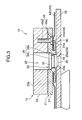
FIG. 3 is a cross-sectional view of a brake pad according to another embodiment. -
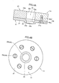
FIG. 4A is a cross-sectional view showing a friction block used in the brake pad shown inFIG. 3 . -
FIG. 4B is a plan view showing the friction block used in the brake pad shown inFIG. 3 . - The following will describe a best mode for carrying out the present invention in detail with reference to the drawings.
-
FIG. 1 shows a brake pad according to an embodiment of the present invention. Thebrake pad 10 according to the present embodiment is used for a disc brake provided in a high-speed rail vehicle. A plurality ofbrake pads 10 are arranged with respect to a rotational surface of a brake disc (not shown). Thebrake pad 10 includes abase member 12 and a plurality offriction blocks 14 mounted to thebase member 12. - The
base member 12 has the shape of an elongated flat plate extending in one direction in plan view. Thebase member 12 is arranged in parallel with a tangential direction to a rotational circumference of the brake disc. Thebase member 12 is made of a metal including iron as a main material. - The
base member 12 has a plurality of throughholes 16 extending therethrough. The throughholes 16 are formed at locations on whichfriction blocks 14 are respectively mounted. The number of throughholes 16 is the same as the number offriction blocks 14 to be mounted. Each throughhole 16 has an expanded outer opening in an outer portion (lower portion of thebase member 12 inFIG. 1 ) of thebase member 12. - The
base member 12 is formed with acurved seat 18 having a concave curved surface in the surface (upper surface of thebase member 12 inFIG. 1 ) of the base that faces thefriction block 14 and around the throughhole 16. Thecurved seat 18 is formed as a recess having a circular shape in plan view, and a curved surface of the recess is aseat surface 18a. The throughhole 16 is at a center of thecurved seat 18. - As shown in
FIGS. 2A and 2B , thefriction block 14 is formed in the shape of a thick disc. Thefriction block 14 may be formed in the shape of a polygon such as triangle, pentagon, and hexagon. In this case, the vertices of the polygon may be preferably rounded. - The
friction block 14 includes areinforcing plate 21 which serves as a support member, and afriction member 23 which is fixedly attached to the reinforcingplate 21. Thefriction block 14 has a throughhole 25 extending through thereinforcing plate 21 and thefriction member 23. The reinforcingplate 21 is made of a metal including iron as a main material. The reinforcingplate 21 includes amain portion 27 in the shape of a circular plate, and anannular portion 29 projecting from themain portion 27. The throughhole 25 extends through a center of themain portion 27. Theannular portion 29 projects from themain portion 27 around the throughhole 25 toward thebase member 12. Theannular portion 29 faces thecurved seat 18. - The
annular portion 29 has an end surface (lower surface) 29a which is convexly curved so as to correspond to theseat surface 18a of the concavecurved seat 18 of thebase member 12. In other words, theend surface 29a of theannular portion 29 agrees with an arc of a circle having a center located on an axis of theannular portion 29. Thefriction block 14 is mounted in a state that a gap exists between theend surface 29a of theannular portion 29 and theseat surface 18a of thecurved seat 18. When theend surface 29a of theannular portion 29 comes into contact with theseat surface 18a of thecurved seat 18, theend surface 29a of theannular portion 29 is slidable over thecurved seat 18 in this contact state. - The
friction member 23 is fixedly attached to the surface (upper surface inFIG. 1 ) of the reinforcingplate 21 that is remote from thebase member 12. Thefriction member 23 is formed in the shape of a thick disc, and the throughhole 25 extends through a center of thefriction member 23. Thefriction member 23 has the same shape as that of the reinforcingplate 21 in plan view. - The
friction member 23 is made of a copper alloy including copper as a main material, and small amounts of metals such as iron, metallic compounds, graphite and/or other additives, these elements being dispersed to obtain a high coefficient of friction even at high temperature. Thefriction member 23 is sintered to be thereby fixedly attached to the reinforcingplate 21. It is noted that thefriction member 23 is not limited to a member made of a sintered metal, but may be made of, for example, a material including reinforcement fiber dispersed in a synthetic resin which is a main material. - The
friction member 23 has a free end surface (end surface distant from thebase member 12 or upper surface inFIG. 1 ) which serves afriction surface 23a. Thefriction surface 23a is to be pressed against the brake disc (not shown), and is a contact surface which is to be brought into contact with the brake disc. - The through
hole 25 of thefriction block 14 has a step which defines a narrow space in the throughhole 25 closer to thebase member 12. Specifically, the throughhole 25 includes astep portion 25a, asmall diameter portion 25b, and alarge diameter portion 25c. Thestep portion 25a is formed in the reinforcingplate 21, and located between thesmall diameter portion 25b and thelarge diameter portion 25c. Thesmall diameter portion 25b is located closer to thebase member 12 with respect to thestep portion 25a, and thelarge diameter portion 25c is located closer to thefriction member 23 with respect to thestep portion 25a. - The through
hole 25 of thefriction block 14 faces the throughhole 16 of thebase member 12. Arivet 30 is inserted in the throughhole 16 of thebase member 12 and the throughhole 25 of thefriction block 14 to thereby couple thefriction block 14 to thebase member 12. - The
rivet 30 includes ahead 32 for preventing therivet 30 from moving off, and amain body 34 which has a diameter smaller than that of thehead 32. The diameter of thehead 32 is smaller than that of thelarge diameter portion 25c of the throughhole 25 of thefriction block 14, and larger than that of thesmall diameter portion 25b. Thehead 32 has a contact surface coming into contact with a contact surface of thestep portion 25a of the throughhole 25 of thefriction block 14 to thereby prevent thefriction block 14 from moving off. - The
main body 34 includes acontact portion 34a coming into contact with thebase member 12, and anintermediate portion 34b between thehead 32 and thecontact portion 34a. Theintermediate portion 34b has a diameter smaller than thehead 32 and thecontact portion 34a. In other words, the diameter of thecontact portion 34a is larger than that of theintermediate portion 34b. - The
contact portion 34a has a diameter smaller than thehead 32 and is in contact with thecurved seat 18 of thebase member 12. - The
main body 34 further includes afastening portion 36 which extends from thecontact portion 34a in the throughhole 16 of thebase member 12. Thefastening portion 36 is formed with an expanded part having a larger diameter in the expanded opening of the throughhole 16 to thereby sandwich thebase member 12 between the expanded part of thefastening portion 36 and thecontact portion 34a. - A distance from the contact surface of the
head 32 to the contact surface of thecontact portion 34a is slightly longer than that from the contact surface of thestep portion 25a to theend surface 29a of theannular portion 29. Thus, in the state where thefriction block 14 is coupled to thebase member 12, there is a slight gap between theend surface 29a of theannular portion 29 and theseat surface 18a of thecurved seat 18. - An
elastic member 40 is provided between thebase member 12 and thefriction block 14. Theelastic member 40 is a metallic disc spring which has a dish shape, and has anopening 40a. Theannular portion 29 is inserted in theopening 40a of theelastic member 40, and theelastic member 40 is located between thebase member 12 and thefriction block 14. - The
elastic member 40 applies an elastic force to thebase member 12 and thefriction block 14 in a direction of separating thebase member 12 and thefriction block 14 from each other. Theelastic member 40 has an elastic coefficient which allows theelastic member 40 to be elastically deformed when thefriction block 14 is pressed against the brake disc to perform braking. Accordingly, theelastic member 40 is elastically deformed by a pressing force transmitted through thefriction block 14 when thefriction block 14 is pressed against the brake disc, which causes thefriction block 14 to be displaced in an up-down direction, or to tilt. - A heat
transfer suppressing member 44 is provided between thefriction block 14 and theelastic member 40. The heattransfer suppressing member 44 is a plate having substantially the same shape and size as thebase member 12 in plan view. - The heat
transfer suppressing member 44 is formed withcontact portions 44a in sections corresponding to the plurality of friction blocks 14, andextension portion 44b extending between thesecontact portions 44a. Eachcontact portion 44a is formed in an annular shape having an inner diameter slightly larger than an outer diameter of theannular portion 29, and an outer diameter slightly larger than an outer circumference of theelastic member 40. The heattransfer suppressing member 44 is arranged in such a way that theannular portion 29 passes through an opening of thecontact portion 44a and thecontact portion 44a comes in contact with thefriction block 14. - The
extension portion 44b connects thecontact portions 44a with one another, and theextension portion 44b is bent on the outer periphery of thecontact portions 44a and extends in substantially parallel with thefriction block 14 while keeping a space from thefriction block 14. - The heat
transfer suppressing member 44 is made of a material having a smaller coefficient of thermal conductivity than thefriction block 14. For example, the heattransfer suppressing member 44 is made of a stainless-steel having a smaller coefficient of thermal conductivity than a cast iron which the reinforcingplate 21 is made of. - A plurality of projections 48 (six projections in this embodiment) are provided in the
friction block 14. Eachprojection 48 includes afirst portion 48a, asecond portion 48b, and ahead portion 48c. Thefirst portion 48a is formed with an external thread which is screwed in a threadedhole 21a formed in themain portion 27 of the reinforcingplate 21. In other words, theprojection 48 is formed with irregularities in a side surface thereof. Thefirst portion 48a has an end which comes into contact with thecontact portion 44a of the heattransfer suppressing member 44 and receives a pushing force of theelastic member 40. - The
second portion 48b is formed in the other portion of theprojection 48 and extends in one direction. Thesecond portion 48b is formed with wide parts and narrow parts alternately in a longitudinal direction thereof to thereby increase the contact area of thesecond portion 48b with thefriction member 23, and prevent thefriction member 23 from separating from the reinforcingplate 21. Thesecond portion 48b may be formed with an external thread as thefirst portion 48a. - The
head portion 48c is located between thefirst portion 48a and thesecond portion 48b. In the present embodiment, thehead portion 48c is formed in the shape of a hexagon bolt head. - The
projection 48 is screwed into the threadedhole 21a of the reinforcingplate 21. In other words, theprojection 48 is fastened to the reinforcingplate 21 by a mechanical fastener. Theprojection 48 is inserted and screwed in the threadedhole 21a from the friction member side, and thehead portion 48c of theprojection 48 comes into contact with the surface of the reinforcingplate 21 that is in contact with thefriction member 23. In other words, theprojection 48 is arranged in such a way that thehead portion 48c more extending in a radial direction than thefirst portion 48a projects from the surface of the reinforcingplate 21 that is in contact with thefriction member 23. - The
projections 48 are arranged in such way that their respective axes are parallel with a direction perpendicular to thefriction surface 23a. Theprojections 48 extend to or near thefriction surface 23a of thefriction member 23. Thus, even if a crack occurs in thefriction member 23 by a shear force generated at braking, the crack can be prevented from developing further by the provision of theprojections 48. - The
friction member 23 is fixedly attached to the reinforcingplate 21 after theprojections 48 are fastened to the reinforcingplate 21. Specifically, after theprojections 48 are mounted to the reinforcingplate 21, thefriction member 23 is sinteredly attached to the reinforcingplate 21 and theprojections 48. Thesecond portion 48b of theprojection 48 is buried in thefriction member 23. Theprojections 48 are kept from loosening off. - In the sintering process where the
friction member 23 is fixedly attached to the reinforcingplate 21, thefriction member 23 is also firmly integrated with theprojections 48. Theprojections 48 are made of a copper alloy which includes copper as a main material and is similar to the material of thefriction member 23. Therefore, in the process where thefriction member 23 is sintered, thefriction member 23 easily integrates with theprojections 48. It is noted that as thefriction member 23 is worn away at braking, theprojections 48 are similarly worn away at the same time. - There is a possibility that in the
brake pad 10 according to the present embodiment, a crack occurs in afriction member 23 by a shear force at braking. However, even in this case, development of the crack is limited to a considerably small extent by theprojections 48. Even if the crack develops to an intermediate portion in thefriction member 23 and causes the likelihood that thefriction member 23 separates into pieces toward the brake disc and the reinforcingplate 21 at the intermediate portion, even a piece of thefriction member 23 will be kept from going away because thefriction member 23 is firmly integrated with theprojection 48 having the irregularities in the side surface thereof. Specifically, theprojections 48 each have the irregularities in the side surface thereof, which increases the contact area of thefriction member 23 with theprojections 48. The irregularities serve to prevent thefriction member 23 from moving in a direction of going away. In this way, the integration of thefriction member 23 with theprojections 48 is high, and thefriction member 23 is prevented from partially breaking off or flying apart. In other words, theprojections 48 prevent a crack from developing to such a degree that thefriction member 23 wholly breaks off or flies apart, and further prevent even a part of thefriction member 23 from breaking off or flying apart. - Especially, in the case that the
brake pad 10 is applied to a high-speed rail vehicle, it is important to ensure a sufficient coefficient of friction of thefriction member 23 at high temperature because thefriction member 23 has a high temperature due to frictional heat. The type and amount of additives are determined from this viewpoint. For this reason, there may be a case of using a friction member which does not have a sufficient toughness in a high temperature region. Even in such this case, in thebrake pad 10 of the present embodiment, the provision of theprojections 48 prevents a crack from developing to such a degree that thefriction member 23 wholly breaks off, and further prevents even a part of thefriction member 23 from breaking off or flying apart. - In addition, even in the case of selecting a material for the friction member in view of a high-speed rail vehicle and need of a high coefficient of friction, in other words, even in the case where the friction member does not have an insufficient toughness as compared with a material which is selected for the friction member in consideration of a toughness of the friction member, the
brake pad 10 of the present embodiment prevents thefriction member 23 from breaking off due to development of a crack. This provides a wider selectability of a material for the friction member in aspects of type and amount of additives. - Further, in the present embodiment, since the
projections 48 are fixedly attached to the reinforcingplate 21 by the mechanical fastener, even a material unsuitable for connection with the reinforcingplate 21 can be used for theprojection 48. This enhances the designability in aspect of material. Theprojections 48 can be more firmly mounted to the reinforcingplate 21. - Further, in the present embodiment, since each
projection 48 is separately formed with thefirst portion 48a and thesecond portion 48b, thefirst portion 48a can be made to have a thread having a shape and a size best suited for the connection with the reinforcingplate 21, and thesecond portion 48b can be made to have irregularities having a shape and a size best suited for the connection with thefriction member 23. Thus, it is easy to satisfy the contrary demands of fastening to the reinforcingplate 21 and integrating with thefriction member 23. - In addition, since the
second portion 48b located in thefriction member 23 have the larger irregularities from thefirst portion 48a, it is unlikely that thefirst portion 48a disengages from thethread hole 21a due to vibrations and other causes. Specifically, since thesecond portion 48b will not engage with the threadedhole 21a of the reinforcingplate 21, thefirst portion 48a is unlikely to disengage from thethread hole 21a. Accordingly, theprojection 48 is reliably prevented from disengaging off. In addition, the larger irregularities of thesecond portion 48b than thefirst portion 48a makes the material of thefriction member 23 easily reach the cuts of thesecond portion 48b. Thus, it is possible to satisfy the contrary demands of fastening to the reinforcingplate 21 and integrating with thefriction member 23. - Further, in the present embodiment, since the
projection 48 and thefriction member 23 are made of materials having the same main material, thefriction member 23 and theprojections 48 are easily integrated with each other in the manufacturing of thebrake pad 10. This increases the integration between thefriction member 23 and theprojections 48, and thefriction member 23 is more effectively prevented from breaking off or flying apart. - The
projection 48 may be formed to reach thefriction surface 23a of thefriction member 23. - Further, although the
brake pad 10 applied to a high-speed rail vehicle has been described in the present embodiment, the present invention is also applicable to vehicles other than a high-speed rail vehicle. - Further, as shown in
FIGS. 3 ,4A, and 4B , aprojection 48 may be constructed by a bolt. In this embodiment, theprojection 48 includes a threadedportion 48d and ahead portion 48e. Ahole 21a which is formed in a reinforcingplate 21 has a small diameter threaded portion and a large diameter portion for receiving thehead portion 48e of theprojection 48 from a base side. Theprojection 48 is engaged with the small diameter threaded portion of thehole 21a and thehead portion 48e is in the large diameter portion of thehole 21a of the reinforcingplate 21. Afriction member 23 is sintered after theprojection 48 is screwed into the reinforcingplate 21. Consequently, thefriction member 23 is fixedly attached to the reinforcingplate 21 and the threadedportion 48d of theprojection 48. Further, thehead portion 48e of theprojection 48 receives the elastic force of anelastic member 40 through a heattransfer suppressing member 44. Theprojection 48 is pressed by the pushing force of theelastic member 40. Hence, theprojection 48 which is mechanically fastened to the reinforcingplate 21 is prevented from disengaging due to vibrations and other causes. Accordingly, theprojection 48 is reliably prevented from breaking off. - In this embodiment, also, each
projection 48 may be formed to reach thefriction surface 23a of thefriction member 23. Further, this embodiment is applicable to vehicles other than a high-speed rail vehicle. - The above embodiments are summarized as follows.
- (1) In the present embodiment, there is a possibility that a crack occurs in the friction member due to a shear force received by the friction member at braking. However, even in this case, the development of the crack is limited to a considerably small range by the projections. The crack is prevented from developing throughout the friction member. Further, even if a crack develops to an extent of causing a likelihood that the friction member separates into pieces toward the brake disc and the support member, the friction member is firmly held by the projections since the friction member is fixedly attached to the projections each having the irregularities in the side surface thereof, and the integration between the friction member and the projections is high. Thus, the friction member is prevented from partially breaking off or flying apart. In other words, the projections prevent a crack from developing to such a degree that the friction member wholly breaks off or flies apart, and prevent the friction member from partially breaking off or flying apart.
- (2) The projections may be fixedly attached to the support member by a mechanical fastener.
In this construction, a material unsuitable for the connection with the support member can be used for the projections. Thus, the degree of freedom of selecting a material in design is improved. Also, the projections are firmly mounted to the support member. - (3) The projections each may include a first portion which is formed with an external thread to be screwed into the support member, and a second portion which is firmly integrated with the friction member.
In this construction, the first portion and the second portion are separately provided in the projection, the first portion is formed with a thread having a shape and a size best suited for the connection with the support member, and the second portion is made with a shape and a size suitable for integration with the friction member. Thus, it is easy to satisfy the contrary demands of fastening to the support member and integrating with the friction member. - (4) The second portion may be formed with irregularities having a larger cut than the external thread of the first portion.
In this construction, the pitch of the external thread (the first portion) which is screwed into the support member having a small thickness is shortened. Thus, the projections are more firmly attached to the support member. On the other hand, if the irregularities of the second portion have small cuts, the friction member is hard to enter the cuts of the irregularities due to the short pitch, making it difficult to firmly hold the friction member. However, in this construction, the irregularities of the second portion have larger cuts than the first portion make the material of the friction member easily enter the cuts of the irregularities of the second portion. Therefore, it is possible to satisfy the contrary demands of fastening to the support member and integrating with the friction member. - (5) The projections each may receive a pushing force from the elastic member at an outer end thereof.
In this construction, since the end of each projection receives the pushing force of the elastic member, the projection mechanically fastened to the support member is prevented from disengaging from the support member due to vibrations and other causes. Accordingly, the projection is reliably prevented from disengaging off. - As described above, according to the present embodiment, the brake pad effectively prevents the friction member from even partially breaking off.
Claims (5)
- A brake pad to be pressed against a brake disc, comprising:a base member;a friction block including a support member, and a friction member fixedly attached to a surface of the support member, the friction block being mounted to the base member;an elastic member provided between the base member and the friction block for allowing the friction block to tilt and move in a direction of approaching the base member when the friction block is pressed against the brake disc; anda plurality of projections which each project from the surface of the support member to which the friction member is fixedly attached, and each extend to a friction surface of the friction member or a vicinity of the friction surface of the friction member, and each have a rugged side surface, the plurality of projections and the friction member being firmly integrated with each other.
- The brake pad according to claim 1, wherein the plurality of projections are fixedly attached to the support member by a mechanical fastener.
- The brake pad according to claim 1 or 2, wherein the plurality of projections each include a first portion which is formed with an external thread to be screwed into the support member, and a second portion which is firmly integrated with the friction member.
- The brake pad according to claim 3, wherein the second portion has irregularities having a larger cut than the external thread.
- The brake pad according to any one of the preceding claims, wherein the plurality of projections each receive a pushing force from the elastic member at an outer end thereof.
Applications Claiming Priority (1)
| Application Number | Priority Date | Filing Date | Title |
|---|---|---|---|
| JP2007204099A JP4917989B2 (en) | 2007-08-06 | 2007-08-06 | Disc pad |
Publications (2)
| Publication Number | Publication Date |
|---|---|
| EP2023000A1 true EP2023000A1 (en) | 2009-02-11 |
| EP2023000B1 EP2023000B1 (en) | 2009-12-30 |
Family
ID=39890266
Family Applications (1)
| Application Number | Title | Priority Date | Filing Date |
|---|---|---|---|
| EP08014029A Not-in-force EP2023000B1 (en) | 2007-08-06 | 2008-08-05 | Brake pad |
Country Status (5)
| Country | Link |
|---|---|
| EP (1) | EP2023000B1 (en) |
| JP (1) | JP4917989B2 (en) |
| CN (1) | CN101363488B (en) |
| AT (1) | ATE453814T1 (en) |
| DE (1) | DE602008000478D1 (en) |
Cited By (11)
| Publication number | Priority date | Publication date | Assignee | Title |
|---|---|---|---|---|
| EP2290257A1 (en) * | 2009-09-01 | 2011-03-02 | Dawin Friction | Friction pad for brake system |
| CN103671656A (en) * | 2013-12-24 | 2014-03-26 | 刘伟 | High-speed train and rail transit vehicle brake pad |
| WO2014161725A1 (en) * | 2013-04-02 | 2014-10-09 | Faiveley Transport Witten Gmbh | Brake lining for partially lined disc brakes, particularly for rail vehicles |
| WO2015019380A3 (en) * | 2013-08-07 | 2015-04-16 | Im-Iniziative Meccaniche S.R.L. | Plate for supporting friction material buttons for disc brakes of railway wheeled vehicles and friction pad comprising said plate |
| EP2703684B1 (en) | 2012-08-31 | 2017-01-04 | Dawin Friction Co., Ltd. | Brake pad |
| DE102016103460A1 (en) * | 2016-02-26 | 2017-08-31 | Knorr-Bremse Systeme für Schienenfahrzeuge GmbH | Brake lining for a partial lining disc brake of a rail vehicle, arrangement of a brake pad on a pad holder and method for mounting a friction element on a pad carrier of a brake pad |
| DE102017121879A1 (en) * | 2017-09-21 | 2019-03-21 | Knorr-Bremse Systeme für Schienenfahrzeuge GmbH | Brake pad for a disc brake |
| US20190203787A1 (en) * | 2015-11-03 | 2019-07-04 | Saf-Holland Gmbh | Brake shoe |
| AT522675A2 (en) * | 2017-10-16 | 2020-12-15 | Beijing Tianyishangjia New Mat Corp Ltd | Protective cushion for a friction body from a brake pad and brake pad |
| EP3473882B1 (en) | 2016-06-15 | 2021-11-24 | Akebono Brake Industry Co., Ltd. | Friction-pad assembly for disc brake |
| CN115507142A (en) * | 2022-10-08 | 2022-12-23 | 哈尔滨新干线轨道交通科技有限公司 | A kind of double disc spring type brake pad for EMU |
Families Citing this family (14)
| Publication number | Priority date | Publication date | Assignee | Title |
|---|---|---|---|---|
| JP5333205B2 (en) | 2009-12-28 | 2013-11-06 | 新日鐵住金株式会社 | Brake lining for railway vehicles |
| JP5512337B2 (en) * | 2010-03-11 | 2014-06-04 | 新日鐵住金株式会社 | Brake lining for railway vehicles |
| US8550220B2 (en) * | 2010-07-01 | 2013-10-08 | Shimano Inc. | Bicycle brake pad |
| TWI427009B (en) * | 2011-01-18 | 2014-02-21 | Nippon Steel & Sumitomo Metal Corp | Rail car with a brake to make |
| CN102506098A (en) * | 2011-10-10 | 2012-06-20 | 天津永恒泰科技有限公司 | Electric floating caliper type brake |
| JP5921997B2 (en) * | 2012-09-18 | 2016-05-24 | ナブテスコ株式会社 | Disc brake pad and brake caliper device |
| RU2716524C2 (en) * | 2015-02-18 | 2020-03-12 | Кофрен С.Р.Л. | Brake pad for railway brakes |
| EP3396194A4 (en) * | 2015-12-25 | 2019-01-16 | Nippon Steel & Sumitomo Metal Corporation | BRAKE LINING FOR RAILWAY RAILWAY EQUIPMENT AND BRAKE DISC HAVING THE SAME |
| JP6567084B2 (en) * | 2015-12-28 | 2019-08-28 | 日本製鉄株式会社 | Railway vehicle brake lining and disc brake equipped with the same |
| BR112018068187A2 (en) * | 2016-03-17 | 2019-01-15 | Nippon Steel & Sumitomo Metal Corp | rail brake lining and rail brake disc brake including the same |
| KR101900388B1 (en) * | 2016-12-23 | 2018-09-20 | 한국철도기술연구원 | Assembly of brake pad |
| CN107573062B (en) * | 2017-08-28 | 2023-08-01 | 天宜上佳(天津)新材料有限公司 | Ceramic material with thermal insulation performance, ceramic-aluminum alloy brake disc prepared therefrom and preparation method thereof |
| IT201800005328A1 (en) * | 2018-05-14 | 2019-11-14 | PAD FOR DISC BRAKES FOR RAILWAY VEHICLES | |
| CN208764199U (en) * | 2018-09-20 | 2019-04-19 | 台州赫兹电气有限公司 | A kind of vibration damping transmission and conjunction device of electromagnetic power-off brake |
Citations (5)
| Publication number | Priority date | Publication date | Assignee | Title |
|---|---|---|---|---|
| DE8514607U1 (en) * | 1985-05-17 | 1985-07-04 | Jurid Werke Gmbh, 2056 Glinde | Carrier plate for brake pads of disc brakes |
| DE4436457A1 (en) * | 1994-10-12 | 1996-04-18 | Knorr Bremse Systeme | Brake pad for partial pad disc brakes, in particular for rail vehicles |
| EP0902210A2 (en) | 1997-09-15 | 1999-03-17 | Goldbach Automobile Consulting GmbH | Lining carrier for a disc brake pad |
| WO2003098068A1 (en) | 2002-05-16 | 2003-11-27 | Knorr-Bremse Systeme für Schienenfahrzeuge GmbH | Brake lining for the disk brake of a vehicle |
| US20030234149A1 (en) * | 2002-06-19 | 2003-12-25 | Zf Sachs Ag | Friction clutch |
Family Cites Families (8)
| Publication number | Priority date | Publication date | Assignee | Title |
|---|---|---|---|---|
| JPS5663136A (en) * | 1979-10-23 | 1981-05-29 | Sumitomo Electric Ind Ltd | Friction pad assembly |
| JPS6263229A (en) * | 1985-09-12 | 1987-03-19 | Sumitomo Electric Ind Ltd | Friction pad assembly |
| JP2919937B2 (en) * | 1990-09-26 | 1999-07-19 | 大成建設株式会社 | Connection structure and connection structure of panel-like material |
| JP3169730B2 (en) * | 1993-02-06 | 2001-05-28 | 株式会社北浦工業 | Fixing method and fixing structure of plate material to screw material |
| GB0106357D0 (en) * | 2001-03-13 | 2001-05-02 | Federal Mogul Friction Product | Friction pad |
| JP2004009461A (en) * | 2002-06-05 | 2004-01-15 | Akio Hiraoka | Bookbinding method, and pipe and bolt used for bookbinding |
| MXPA05005904A (en) * | 2002-12-05 | 2006-02-08 | Goldbach Automobile Consulting | Disc brake comprising a lining support. |
| JP2005083523A (en) * | 2003-09-10 | 2005-03-31 | Sugano Masato | Connecting screw fitting |
-
2007
- 2007-08-06 JP JP2007204099A patent/JP4917989B2/en not_active Expired - Fee Related
-
2008
- 2008-08-05 AT AT08014029T patent/ATE453814T1/en not_active IP Right Cessation
- 2008-08-05 EP EP08014029A patent/EP2023000B1/en not_active Not-in-force
- 2008-08-05 DE DE602008000478T patent/DE602008000478D1/en active Active
- 2008-08-06 CN CN2008101461086A patent/CN101363488B/en not_active Expired - Fee Related
Patent Citations (5)
| Publication number | Priority date | Publication date | Assignee | Title |
|---|---|---|---|---|
| DE8514607U1 (en) * | 1985-05-17 | 1985-07-04 | Jurid Werke Gmbh, 2056 Glinde | Carrier plate for brake pads of disc brakes |
| DE4436457A1 (en) * | 1994-10-12 | 1996-04-18 | Knorr Bremse Systeme | Brake pad for partial pad disc brakes, in particular for rail vehicles |
| EP0902210A2 (en) | 1997-09-15 | 1999-03-17 | Goldbach Automobile Consulting GmbH | Lining carrier for a disc brake pad |
| WO2003098068A1 (en) | 2002-05-16 | 2003-11-27 | Knorr-Bremse Systeme für Schienenfahrzeuge GmbH | Brake lining for the disk brake of a vehicle |
| US20030234149A1 (en) * | 2002-06-19 | 2003-12-25 | Zf Sachs Ag | Friction clutch |
Cited By (20)
| Publication number | Priority date | Publication date | Assignee | Title |
|---|---|---|---|---|
| EP2290257A1 (en) * | 2009-09-01 | 2011-03-02 | Dawin Friction | Friction pad for brake system |
| EP2703684B1 (en) | 2012-08-31 | 2017-01-04 | Dawin Friction Co., Ltd. | Brake pad |
| WO2014161725A1 (en) * | 2013-04-02 | 2014-10-09 | Faiveley Transport Witten Gmbh | Brake lining for partially lined disc brakes, particularly for rail vehicles |
| RU2654657C2 (en) * | 2013-08-07 | 2018-05-21 | Им-Инициативе Мекканике С.Р.Л. | Plate for supporting friction material buttons for disc brakes of railway wheeled vehicles and friction pad comprising said plate |
| WO2015019380A3 (en) * | 2013-08-07 | 2015-04-16 | Im-Iniziative Meccaniche S.R.L. | Plate for supporting friction material buttons for disc brakes of railway wheeled vehicles and friction pad comprising said plate |
| CN103671656A (en) * | 2013-12-24 | 2014-03-26 | 刘伟 | High-speed train and rail transit vehicle brake pad |
| CN103671656B (en) * | 2013-12-24 | 2016-09-07 | 刘伟 | Bullet train and rail transit vehicle brake pad |
| US20190203787A1 (en) * | 2015-11-03 | 2019-07-04 | Saf-Holland Gmbh | Brake shoe |
| US10781873B2 (en) * | 2015-11-03 | 2020-09-22 | Saf-Holland Gmbh | Brake shoe |
| DE102016103460A1 (en) * | 2016-02-26 | 2017-08-31 | Knorr-Bremse Systeme für Schienenfahrzeuge GmbH | Brake lining for a partial lining disc brake of a rail vehicle, arrangement of a brake pad on a pad holder and method for mounting a friction element on a pad carrier of a brake pad |
| EP3473882B1 (en) | 2016-06-15 | 2021-11-24 | Akebono Brake Industry Co., Ltd. | Friction-pad assembly for disc brake |
| EP3473882B2 (en) † | 2016-06-15 | 2025-12-31 | Akebono Brake Industry Co., Ltd. | Friction-pad assembly for disc brake |
| DE102017121879A1 (en) * | 2017-09-21 | 2019-03-21 | Knorr-Bremse Systeme für Schienenfahrzeuge GmbH | Brake pad for a disc brake |
| WO2019057684A1 (en) * | 2017-09-21 | 2019-03-28 | Knorr-Bremse Systeme für Schienenfahrzeuge GmbH | BRAKE PAD FOR A DISC BRAKE |
| US11536329B2 (en) | 2017-09-21 | 2022-12-27 | Knorr-Bremse Systeme für Schienenfahrzeuge GmbH | Brake pad for a disk brake |
| AT522675A2 (en) * | 2017-10-16 | 2020-12-15 | Beijing Tianyishangjia New Mat Corp Ltd | Protective cushion for a friction body from a brake pad and brake pad |
| AT522675A5 (en) * | 2017-10-16 | 2021-01-15 | Beijing Tianyishangjia New Mat Corp Ltd | Protective cushion for a friction body from a brake pad and brake pad |
| ES2761073R1 (en) * | 2017-10-16 | 2021-02-10 | Beijing Tianyishangjia New Mat Corp Ltd | A brake pad and its protective friction body pad |
| AT522675B1 (en) * | 2017-10-16 | 2021-07-15 | Beijing Tianyishangjia New Mat Corp Ltd | Protective cushion for a friction body from a brake pad and brake pad |
| CN115507142A (en) * | 2022-10-08 | 2022-12-23 | 哈尔滨新干线轨道交通科技有限公司 | A kind of double disc spring type brake pad for EMU |
Also Published As
| Publication number | Publication date |
|---|---|
| EP2023000B1 (en) | 2009-12-30 |
| CN101363488A (en) | 2009-02-11 |
| HK1125436A1 (en) | 2009-08-07 |
| JP4917989B2 (en) | 2012-04-18 |
| ATE453814T1 (en) | 2010-01-15 |
| CN101363488B (en) | 2012-03-28 |
| DE602008000478D1 (en) | 2010-02-11 |
| JP2009041583A (en) | 2009-02-26 |
Similar Documents
| Publication | Publication Date | Title |
|---|---|---|
| EP2023000B1 (en) | Brake pad | |
| CN103842681B (en) | Disc brakes especially for commercial vehicles and brake linings for disc brakes | |
| JP5512337B2 (en) | Brake lining for railway vehicles | |
| CN100394062C (en) | brake disc friction block | |
| JP5113079B2 (en) | Brake pad for disc brake | |
| EP2290257A1 (en) | Friction pad for brake system | |
| KR101772609B1 (en) | Brake pads for railway vehicle using seesaw type structure | |
| US11162552B2 (en) | Friction pad assembly for disc brakes | |
| US11242902B2 (en) | Brake disc and method for producing a brake disc | |
| KR20140104409A (en) | Disk brake and brake pad for a disk brake | |
| JP4701512B2 (en) | Brake disc for railway vehicles | |
| US7500546B2 (en) | Brake lining cup attachment method for reduced wear | |
| EP2023002B2 (en) | Pad for disk brake | |
| JP6202434B2 (en) | Disc brake device | |
| US12264715B2 (en) | Brake pad backing plate | |
| JP4478067B2 (en) | Wheels with brake discs for railway vehicles | |
| JP2016504538A (en) | Brake shoe and brake shoe manufacturing method | |
| JP4631803B2 (en) | Opposite type disc brake | |
| HK1125436B (en) | Brake pad | |
| JP4932786B2 (en) | Disc brake pad | |
| KR101900388B1 (en) | Assembly of brake pad | |
| JPH06207631A (en) | Inner shim attaching structure in disc brake | |
| JPH0741089U (en) | Brake pad | |
| JP2007051737A (en) | Disc brake | |
| JPH06200965A (en) | Fitting construction of outer shim for disc brake |
Legal Events
| Date | Code | Title | Description |
|---|---|---|---|
| PUAI | Public reference made under article 153(3) epc to a published international application that has entered the european phase |
Free format text: ORIGINAL CODE: 0009012 |
|
| AK | Designated contracting states |
Kind code of ref document: A1 Designated state(s): AT BE BG CH CY CZ DE DK EE ES FI FR GB GR HR HU IE IS IT LI LT LU LV MC MT NL NO PL PT RO SE SI SK TR |
|
| AX | Request for extension of the european patent |
Extension state: AL BA MK RS |
|
| 17P | Request for examination filed |
Effective date: 20090514 |
|
| GRAP | Despatch of communication of intention to grant a patent |
Free format text: ORIGINAL CODE: EPIDOSNIGR1 |
|
| AKX | Designation fees paid |
Designated state(s): AT BE BG CH CY CZ DE DK EE ES FI FR GB GR HR HU IE IS IT LI LT LU LV MC MT NL NO PL PT RO SE SI SK TR |
|
| GRAS | Grant fee paid |
Free format text: ORIGINAL CODE: EPIDOSNIGR3 |
|
| GRAA | (expected) grant |
Free format text: ORIGINAL CODE: 0009210 |
|
| AK | Designated contracting states |
Kind code of ref document: B1 Designated state(s): AT BE BG CH CY CZ DE DK EE ES FI FR GB GR HR HU IE IS IT LI LT LU LV MC MT NL NO PL PT RO SE SI SK TR |
|
| REG | Reference to a national code |
Ref country code: GB Ref legal event code: FG4D |
|
| REG | Reference to a national code |
Ref country code: CH Ref legal event code: EP |
|
| REG | Reference to a national code |
Ref country code: IE Ref legal event code: FG4D |
|
| REF | Corresponds to: |
Ref document number: 602008000478 Country of ref document: DE Date of ref document: 20100211 Kind code of ref document: P |
|
| PG25 | Lapsed in a contracting state [announced via postgrant information from national office to epo] |
Ref country code: FI Free format text: LAPSE BECAUSE OF FAILURE TO SUBMIT A TRANSLATION OF THE DESCRIPTION OR TO PAY THE FEE WITHIN THE PRESCRIBED TIME-LIMIT Effective date: 20091230 Ref country code: NO Free format text: LAPSE BECAUSE OF FAILURE TO SUBMIT A TRANSLATION OF THE DESCRIPTION OR TO PAY THE FEE WITHIN THE PRESCRIBED TIME-LIMIT Effective date: 20100330 Ref country code: LT Free format text: LAPSE BECAUSE OF FAILURE TO SUBMIT A TRANSLATION OF THE DESCRIPTION OR TO PAY THE FEE WITHIN THE PRESCRIBED TIME-LIMIT Effective date: 20091230 Ref country code: SE Free format text: LAPSE BECAUSE OF FAILURE TO SUBMIT A TRANSLATION OF THE DESCRIPTION OR TO PAY THE FEE WITHIN THE PRESCRIBED TIME-LIMIT Effective date: 20091230 |
|
| REG | Reference to a national code |
Ref country code: NL Ref legal event code: VDEP Effective date: 20091230 |
|
| LTIE | Lt: invalidation of european patent or patent extension |
Effective date: 20091230 |
|
| PG25 | Lapsed in a contracting state [announced via postgrant information from national office to epo] |
Ref country code: LV Free format text: LAPSE BECAUSE OF FAILURE TO SUBMIT A TRANSLATION OF THE DESCRIPTION OR TO PAY THE FEE WITHIN THE PRESCRIBED TIME-LIMIT Effective date: 20091230 Ref country code: SI Free format text: LAPSE BECAUSE OF FAILURE TO SUBMIT A TRANSLATION OF THE DESCRIPTION OR TO PAY THE FEE WITHIN THE PRESCRIBED TIME-LIMIT Effective date: 20091230 Ref country code: PL Free format text: LAPSE BECAUSE OF FAILURE TO SUBMIT A TRANSLATION OF THE DESCRIPTION OR TO PAY THE FEE WITHIN THE PRESCRIBED TIME-LIMIT Effective date: 20091230 Ref country code: HR Free format text: LAPSE BECAUSE OF FAILURE TO SUBMIT A TRANSLATION OF THE DESCRIPTION OR TO PAY THE FEE WITHIN THE PRESCRIBED TIME-LIMIT Effective date: 20091230 |
|
| PG25 | Lapsed in a contracting state [announced via postgrant information from national office to epo] |
Ref country code: AT Free format text: LAPSE BECAUSE OF FAILURE TO SUBMIT A TRANSLATION OF THE DESCRIPTION OR TO PAY THE FEE WITHIN THE PRESCRIBED TIME-LIMIT Effective date: 20091230 |
|
| PG25 | Lapsed in a contracting state [announced via postgrant information from national office to epo] |
Ref country code: ES Free format text: LAPSE BECAUSE OF FAILURE TO SUBMIT A TRANSLATION OF THE DESCRIPTION OR TO PAY THE FEE WITHIN THE PRESCRIBED TIME-LIMIT Effective date: 20100410 Ref country code: BG Free format text: LAPSE BECAUSE OF FAILURE TO SUBMIT A TRANSLATION OF THE DESCRIPTION OR TO PAY THE FEE WITHIN THE PRESCRIBED TIME-LIMIT Effective date: 20100330 Ref country code: NL Free format text: LAPSE BECAUSE OF FAILURE TO SUBMIT A TRANSLATION OF THE DESCRIPTION OR TO PAY THE FEE WITHIN THE PRESCRIBED TIME-LIMIT Effective date: 20091230 Ref country code: RO Free format text: LAPSE BECAUSE OF FAILURE TO SUBMIT A TRANSLATION OF THE DESCRIPTION OR TO PAY THE FEE WITHIN THE PRESCRIBED TIME-LIMIT Effective date: 20091230 Ref country code: IS Free format text: LAPSE BECAUSE OF FAILURE TO SUBMIT A TRANSLATION OF THE DESCRIPTION OR TO PAY THE FEE WITHIN THE PRESCRIBED TIME-LIMIT Effective date: 20100430 Ref country code: EE Free format text: LAPSE BECAUSE OF FAILURE TO SUBMIT A TRANSLATION OF THE DESCRIPTION OR TO PAY THE FEE WITHIN THE PRESCRIBED TIME-LIMIT Effective date: 20091230 |
|
| PG25 | Lapsed in a contracting state [announced via postgrant information from national office to epo] |
Ref country code: SK Free format text: LAPSE BECAUSE OF FAILURE TO SUBMIT A TRANSLATION OF THE DESCRIPTION OR TO PAY THE FEE WITHIN THE PRESCRIBED TIME-LIMIT Effective date: 20091230 Ref country code: CZ Free format text: LAPSE BECAUSE OF FAILURE TO SUBMIT A TRANSLATION OF THE DESCRIPTION OR TO PAY THE FEE WITHIN THE PRESCRIBED TIME-LIMIT Effective date: 20091230 Ref country code: BE Free format text: LAPSE BECAUSE OF FAILURE TO SUBMIT A TRANSLATION OF THE DESCRIPTION OR TO PAY THE FEE WITHIN THE PRESCRIBED TIME-LIMIT Effective date: 20091230 |
|
| PG25 | Lapsed in a contracting state [announced via postgrant information from national office to epo] |
Ref country code: CY Free format text: LAPSE BECAUSE OF FAILURE TO SUBMIT A TRANSLATION OF THE DESCRIPTION OR TO PAY THE FEE WITHIN THE PRESCRIBED TIME-LIMIT Effective date: 20091230 Ref country code: GR Free format text: LAPSE BECAUSE OF FAILURE TO SUBMIT A TRANSLATION OF THE DESCRIPTION OR TO PAY THE FEE WITHIN THE PRESCRIBED TIME-LIMIT Effective date: 20100331 |
|
| PLBE | No opposition filed within time limit |
Free format text: ORIGINAL CODE: 0009261 |
|
| STAA | Information on the status of an ep patent application or granted ep patent |
Free format text: STATUS: NO OPPOSITION FILED WITHIN TIME LIMIT |
|
| 26N | No opposition filed |
Effective date: 20101001 |
|
| PG25 | Lapsed in a contracting state [announced via postgrant information from national office to epo] |
Ref country code: DK Free format text: LAPSE BECAUSE OF FAILURE TO SUBMIT A TRANSLATION OF THE DESCRIPTION OR TO PAY THE FEE WITHIN THE PRESCRIBED TIME-LIMIT Effective date: 20091230 |
|
| PG25 | Lapsed in a contracting state [announced via postgrant information from national office to epo] |
Ref country code: IT Free format text: LAPSE BECAUSE OF FAILURE TO SUBMIT A TRANSLATION OF THE DESCRIPTION OR TO PAY THE FEE WITHIN THE PRESCRIBED TIME-LIMIT Effective date: 20091230 Ref country code: MC Free format text: LAPSE BECAUSE OF NON-PAYMENT OF DUE FEES Effective date: 20100831 |
|
| PG25 | Lapsed in a contracting state [announced via postgrant information from national office to epo] |
Ref country code: IE Free format text: LAPSE BECAUSE OF NON-PAYMENT OF DUE FEES Effective date: 20100805 |
|
| PG25 | Lapsed in a contracting state [announced via postgrant information from national office to epo] |
Ref country code: MT Free format text: LAPSE BECAUSE OF FAILURE TO SUBMIT A TRANSLATION OF THE DESCRIPTION OR TO PAY THE FEE WITHIN THE PRESCRIBED TIME-LIMIT Effective date: 20091230 |
|
| PG25 | Lapsed in a contracting state [announced via postgrant information from national office to epo] |
Ref country code: LU Free format text: LAPSE BECAUSE OF NON-PAYMENT OF DUE FEES Effective date: 20100805 Ref country code: HU Free format text: LAPSE BECAUSE OF FAILURE TO SUBMIT A TRANSLATION OF THE DESCRIPTION OR TO PAY THE FEE WITHIN THE PRESCRIBED TIME-LIMIT Effective date: 20100701 |
|
| PG25 | Lapsed in a contracting state [announced via postgrant information from national office to epo] |
Ref country code: TR Free format text: LAPSE BECAUSE OF FAILURE TO SUBMIT A TRANSLATION OF THE DESCRIPTION OR TO PAY THE FEE WITHIN THE PRESCRIBED TIME-LIMIT Effective date: 20091230 |
|
| REG | Reference to a national code |
Ref country code: CH Ref legal event code: PL |
|
| PG25 | Lapsed in a contracting state [announced via postgrant information from national office to epo] |
Ref country code: CH Free format text: LAPSE BECAUSE OF NON-PAYMENT OF DUE FEES Effective date: 20120831 Ref country code: LI Free format text: LAPSE BECAUSE OF NON-PAYMENT OF DUE FEES Effective date: 20120831 |
|
| PG25 | Lapsed in a contracting state [announced via postgrant information from national office to epo] |
Ref country code: PT Free format text: LAPSE BECAUSE OF NON-PAYMENT OF DUE FEES Effective date: 20091230 |
|
| PGFP | Annual fee paid to national office [announced via postgrant information from national office to epo] |
Ref country code: DE Payment date: 20140730 Year of fee payment: 7 |
|
| PGFP | Annual fee paid to national office [announced via postgrant information from national office to epo] |
Ref country code: GB Payment date: 20140730 Year of fee payment: 7 Ref country code: FR Payment date: 20140808 Year of fee payment: 7 |
|
| REG | Reference to a national code |
Ref country code: DE Ref legal event code: R119 Ref document number: 602008000478 Country of ref document: DE |
|
| GBPC | Gb: european patent ceased through non-payment of renewal fee |
Effective date: 20150805 |
|
| REG | Reference to a national code |
Ref country code: FR Ref legal event code: ST Effective date: 20160429 |
|
| PG25 | Lapsed in a contracting state [announced via postgrant information from national office to epo] |
Ref country code: GB Free format text: LAPSE BECAUSE OF NON-PAYMENT OF DUE FEES Effective date: 20150805 Ref country code: DE Free format text: LAPSE BECAUSE OF NON-PAYMENT OF DUE FEES Effective date: 20160301 |
|
| PG25 | Lapsed in a contracting state [announced via postgrant information from national office to epo] |
Ref country code: FR Free format text: LAPSE BECAUSE OF NON-PAYMENT OF DUE FEES Effective date: 20150831 |