EP2022421B1 - Periphere Katheteranordnung mit Hämostasisventil - Google Patents
Periphere Katheteranordnung mit Hämostasisventil Download PDFInfo
- Publication number
- EP2022421B1 EP2022421B1 EP07113607A EP07113607A EP2022421B1 EP 2022421 B1 EP2022421 B1 EP 2022421B1 EP 07113607 A EP07113607 A EP 07113607A EP 07113607 A EP07113607 A EP 07113607A EP 2022421 B1 EP2022421 B1 EP 2022421B1
- Authority
- EP
- European Patent Office
- Prior art keywords
- catheter
- catheter hub
- catheter assembly
- peripheral
- septum seal
- Prior art date
- Legal status (The legal status is an assumption and is not a legal conclusion. Google has not performed a legal analysis and makes no representation as to the accuracy of the status listed.)
- Active
Links
- 230000002093 peripheral effect Effects 0.000 title claims abstract description 37
- 230000023597 hemostasis Effects 0.000 title 1
- 238000007789 sealing Methods 0.000 claims abstract description 49
- 238000001802 infusion Methods 0.000 claims abstract description 28
- 239000011505 plaster Substances 0.000 claims description 11
- 230000004044 response Effects 0.000 claims description 5
- 238000006073 displacement reaction Methods 0.000 claims description 4
- 239000003978 infusion fluid Substances 0.000 claims description 4
- 238000004873 anchoring Methods 0.000 claims description 2
- 239000008280 blood Substances 0.000 abstract description 8
- 210000004369 blood Anatomy 0.000 abstract description 8
- 210000003462 vein Anatomy 0.000 description 16
- 239000012530 fluid Substances 0.000 description 11
- 239000012528 membrane Substances 0.000 description 10
- 238000004891 communication Methods 0.000 description 6
- 239000003292 glue Substances 0.000 description 6
- 239000000853 adhesive Substances 0.000 description 5
- 230000001070 adhesive effect Effects 0.000 description 5
- 239000002184 metal Substances 0.000 description 5
- 238000000034 method Methods 0.000 description 5
- 239000007924 injection Substances 0.000 description 4
- 238000002347 injection Methods 0.000 description 4
- 230000000295 complement effect Effects 0.000 description 3
- 238000001990 intravenous administration Methods 0.000 description 3
- 239000000126 substance Substances 0.000 description 3
- 239000004812 Fluorinated ethylene propylene Substances 0.000 description 2
- 230000017531 blood circulation Effects 0.000 description 2
- 238000013461 design Methods 0.000 description 2
- 238000003780 insertion Methods 0.000 description 2
- 230000037431 insertion Effects 0.000 description 2
- 239000007788 liquid Substances 0.000 description 2
- 239000000463 material Substances 0.000 description 2
- 230000035515 penetration Effects 0.000 description 2
- 229920009441 perflouroethylene propylene Polymers 0.000 description 2
- 210000003281 pleural cavity Anatomy 0.000 description 2
- 206010001526 Air embolism Diseases 0.000 description 1
- 208000002151 Pleural effusion Diseases 0.000 description 1
- 206010052428 Wound Diseases 0.000 description 1
- 230000004323 axial length Effects 0.000 description 1
- 230000004888 barrier function Effects 0.000 description 1
- 239000010836 blood and blood product Substances 0.000 description 1
- 229940125691 blood product Drugs 0.000 description 1
- 230000006835 compression Effects 0.000 description 1
- 238000007906 compression Methods 0.000 description 1
- 230000005494 condensation Effects 0.000 description 1
- 238000009833 condensation Methods 0.000 description 1
- 238000011109 contamination Methods 0.000 description 1
- 239000003814 drug Substances 0.000 description 1
- 229940079593 drug Drugs 0.000 description 1
- 239000000428 dust Substances 0.000 description 1
- HQQADJVZYDDRJT-UHFFFAOYSA-N ethene;prop-1-ene Chemical group C=C.CC=C HQQADJVZYDDRJT-UHFFFAOYSA-N 0.000 description 1
- 210000000245 forearm Anatomy 0.000 description 1
- 238000001746 injection moulding Methods 0.000 description 1
- 238000009434 installation Methods 0.000 description 1
- 238000003032 molecular docking Methods 0.000 description 1
- 235000015097 nutrients Nutrition 0.000 description 1
- 210000000056 organ Anatomy 0.000 description 1
- 239000002245 particle Substances 0.000 description 1
- 230000000149 penetrating effect Effects 0.000 description 1
- 229920000642 polymer Polymers 0.000 description 1
- 239000004814 polyurethane Substances 0.000 description 1
- 239000004800 polyvinyl chloride Substances 0.000 description 1
- 230000001681 protective effect Effects 0.000 description 1
- 239000000565 sealant Substances 0.000 description 1
- 238000002560 therapeutic procedure Methods 0.000 description 1
Images


Classifications
-
- A—HUMAN NECESSITIES
- A61—MEDICAL OR VETERINARY SCIENCE; HYGIENE
- A61M—DEVICES FOR INTRODUCING MEDIA INTO, OR ONTO, THE BODY; DEVICES FOR TRANSDUCING BODY MEDIA OR FOR TAKING MEDIA FROM THE BODY; DEVICES FOR PRODUCING OR ENDING SLEEP OR STUPOR
- A61M25/00—Catheters; Hollow probes
- A61M25/01—Introducing, guiding, advancing, emplacing or holding catheters
- A61M25/06—Body-piercing guide needles or the like
-
- A—HUMAN NECESSITIES
- A61—MEDICAL OR VETERINARY SCIENCE; HYGIENE
- A61M—DEVICES FOR INTRODUCING MEDIA INTO, OR ONTO, THE BODY; DEVICES FOR TRANSDUCING BODY MEDIA OR FOR TAKING MEDIA FROM THE BODY; DEVICES FOR PRODUCING OR ENDING SLEEP OR STUPOR
- A61M39/00—Tubes, tube connectors, tube couplings, valves, access sites or the like, specially adapted for medical use
- A61M39/02—Access sites
- A61M39/06—Haemostasis valves, i.e. gaskets sealing around a needle, catheter or the like, closing on removal thereof
- A61M39/0606—Haemostasis valves, i.e. gaskets sealing around a needle, catheter or the like, closing on removal thereof without means for adjusting the seal opening or pressure
-
- A—HUMAN NECESSITIES
- A61—MEDICAL OR VETERINARY SCIENCE; HYGIENE
- A61M—DEVICES FOR INTRODUCING MEDIA INTO, OR ONTO, THE BODY; DEVICES FOR TRANSDUCING BODY MEDIA OR FOR TAKING MEDIA FROM THE BODY; DEVICES FOR PRODUCING OR ENDING SLEEP OR STUPOR
- A61M39/00—Tubes, tube connectors, tube couplings, valves, access sites or the like, specially adapted for medical use
- A61M39/02—Access sites
- A61M39/06—Haemostasis valves, i.e. gaskets sealing around a needle, catheter or the like, closing on removal thereof
- A61M2039/062—Haemostasis valves, i.e. gaskets sealing around a needle, catheter or the like, closing on removal thereof used with a catheter
-
- A—HUMAN NECESSITIES
- A61—MEDICAL OR VETERINARY SCIENCE; HYGIENE
- A61M—DEVICES FOR INTRODUCING MEDIA INTO, OR ONTO, THE BODY; DEVICES FOR TRANSDUCING BODY MEDIA OR FOR TAKING MEDIA FROM THE BODY; DEVICES FOR PRODUCING OR ENDING SLEEP OR STUPOR
- A61M25/00—Catheters; Hollow probes
- A61M25/0097—Catheters; Hollow probes characterised by the hub
-
- A—HUMAN NECESSITIES
- A61—MEDICAL OR VETERINARY SCIENCE; HYGIENE
- A61M—DEVICES FOR INTRODUCING MEDIA INTO, OR ONTO, THE BODY; DEVICES FOR TRANSDUCING BODY MEDIA OR FOR TAKING MEDIA FROM THE BODY; DEVICES FOR PRODUCING OR ENDING SLEEP OR STUPOR
- A61M25/00—Catheters; Hollow probes
- A61M25/01—Introducing, guiding, advancing, emplacing or holding catheters
- A61M25/06—Body-piercing guide needles or the like
- A61M25/0693—Flashback chambers
Definitions
- the present invention relates to a peripheral catheter assembly
- a peripheral catheter assembly comprising a hollow catheter hub having a female proximal end and a distal end provided with a catheter tube, at least one infusion port located between said distal end and said proximal end, a hollow needle module comprising a needle hold by a male socket arranged to sealingly engage the female proximal end, and a sealing member engaged inside the catheter hub.
- the invention is defined in claim 1.
- Indications for establishing intravenous access using a peripheral vein catheter can e.g. be the needs for administration of liquids, drugs or nutrients or transfusion of blood or blood products.
- a peripheral vein catheter a small, flexible tube is used to deliver fluids into the body.
- Venflon TM obtainable from Becton Dickinson Infusion Therapy, Helsingborg, Sweden, comprise a hollow main body with a female end plug accommodating a needle hub with a male socket carrying a puncture needle for inserting a catheter into the vein, usually in the back of the hand or in the forearm.
- a common Venflon TM has an infusion port perpendicular to the main body. The infusion port is fluid sealed from the main body simply by means of a short piece of an axially compressible, hollow tube inserted inside the main body just below the infusion port.
- an over-the-needle catheter comprising a hub without infusion port.
- the hub is permanently equipped with a sharp pointed cannula, in the same manner as a trocar.
- a T-shaped septum seal is mounted on the end of a metal tube, which is firmly fixed inside the hub.
- the T-shaped septum seal consists of a shank, i.e. a short, narrow tubular portion, and a head portion with a small central weakened portion.
- the T-shaped septum seal is slidably arranged on the metal tube, causing the metal tube to penetrate the weakened portion and open a permanent flow path through the bores of the cannula and the metal tube upon forward movement of the T-shaped septum seal towards the cannula.
- a conical male luer connector may be used for pushing the T-shaped septum seal forward to provide permanently and irreversibly penetration of the weakened portion.
- a disadvantage of this design is that if the male luer connector is disconnected the T-shaped septum seal cannot close again and the flow passage is open.
- the thin shank of the T-shaped septum seal has no sealing capacity. This shank only serves as a guide and mounting member when pushing the T-shaped septum seal along the axial length of the metal tube, and the T-shaped septum seal cannot be retracted once it has been pushed forward.
- US 5,041,097 describes an intravenous catheter with a protective end seal at the connection end for preventing fluid leakage during installation, connection, and use.
- a thin membrane seal formed of resilient, stretchable material is secured over the opening at the exterior surface of the rear end of the catheter base.
- a needle with a bevelled front end is installed in the catheter.
- the bevelled front end of the needle is pushed through the membrane seal to puncture the membrane seal, which seal is stretched as the forward motion of the needle continues, and conforms to the profile of the needle base and allow it to engage the interior of the catheter base.
- a male luer connector can be installed in the base in a similar forceably manner.
- Both the needle base and the male luer connector must expand the small puncture hole in the stretchable membrane considerably to create sufficient bulk space for the base or connector.
- the major force which is required to allow this entails a considerable risk that the membrane seal either bursts or is pulled out of its attachment.
- the membrane seal is unable to close the flow path through the base again if e.g. the male luer connector is disconnected.
- the elastic membrane seal is susceptible to be detached from the base when subjected to the pushing forward force.
- US patent no. 6,213,978 relates to an intravenous catheter insertion apparatus having a catheter integral with a pre-slit injection site, a blunt cannula adapted for piercing the septum of the pre-slit injection site, and a tube slidably housing a needle.
- the needle is extended through the aligned bores of the catheter, injection site, and blunt cannula, leaving a portion of the needle tip projecting from the end of the catheter in order to insert the catheter into the patient's vein through venipuncture.
- the needle is withdrawn, the needle slide locking in the tube housing after use in order to prevent accidental needle puncture wounds.
- the blunt cannula is also removable, leaving the septum of the injection site sealed to prevent back flow or spurting of blood from the catheter.
- a peripheral vein catheter assembly of the kind mentioned in the opening paragraph that remedies the disadvantages and shortcomings of the prior art peripheral vein catheters.
- a peripheral vein catheter assembly of the kind mentioned in the opening paragraph, which self-closes the flow path when the needle is removed after venipuncture, and opens a flow path in response to introduction of a male part in the catheter hub.
- a sealing valve which can be implemented in a conventional catheter hub with an infusion port.
- a septum seal is to be understood as a flexible, fluid-tight, sealing structure which divides a hollow structure, such as the bore of a catheter hub, into two hollow sections adjacent each other and separated by the septum seal.
- the sealing member is a sealing valve comprising a septum seal having a weakened portion surrounded by deflectable septum walls.
- the sealing valve also has a hollow tubular extension, which protrudes towards a free end from the periphery of the septum seal and extends inside the catheter hub past the infusion port towards the distal end of the catheter hub.
- the catheter hub is provided with an annular relief for at least partly receiving the deflected septum seal wall and/or a part of the wall of the tubular extension displaced by the deflected septum seal wall when e.g. a male luer connector or the male socket is introduced through the weakened portion of the septum seal.
- the deflected septum seal wall easily conforms around the introduced object and serves together with the wall of the tubular extension as a combined sealant between the object and the interior wall of the catheter hub.
- the septum seal completely closes and seals the female proximal end of the hollow catheter hub. This prevents blood from emerging from the catheter hub after venipuncture and the risk of an air embolism is substantially reduced or even eliminated.
- the weakened portion of the deflectable septum wall allows this wall to be penetrated by the needle without substantially impact on the surrounding deflectable wall.
- the sealing valve self-closes.
- a wider or more bulky object such as a male luer connector or the male socket
- the interior of the hollow tubular extension adjacent the female proximal end advantageously serves for receiving the deflected septum seal wall.
- the tubular extension sealingly engages the interior wall of the catheter hub at the section of the tubular extension, which extends past and below the infusion port. As a result, the sealing valve seals both the entrances, i.e.
- the circumferential wall of the tubular extension is able to yield in response to an infusion fluid, which is forceably injected through the infusion port, to thereby allow the infusion fluid to flow further into the vein.
- At least the tubular extension may be provided with at least one securing means for firmly securing the sealing valve inside the catheter hub to prevent axial and/or rotational displacement of the sealing valve inside the catheter hub.
- the septum seal can be provided with securing means.
- securing means may be for foreseen within the scope of the present invention and combinations of these may be used.
- the securing means can just be an adhesive substance such as glue, which additionally may provide sealing.
- glue an adhesive substance
- the securing means can just be an adhesive substance such as glue, which additionally may provide sealing.
- glue an adhesive substance used to secure the tubular extension
- only the part of the tubular extension adjacent the septum seal may be adhered to the interior of the catheter hub.
- At least a part of the length of the tubular extension that extends past and below the infusion port is left free of glue to allow unobstructed compression of the tubular extension in response to infusion of an infusion fluid through the infusion port.
- the securing means may comprise a circumferential sealing rib and one or more anchoring ribs extending in the axial direction of the tubular extension between the septum seal and the circumferential sealing rib, which ribs are forced fitted into engagement with the proximal end of the catheter hub.
- the ribs may be forced fitted into complementary shaped grooves provided in the wall of the catheter hub.
- the ribs may be provided on the inside of the catheter hub and the grooves may be provided on the tubular extension.
- This embodiment leaves less space for receiving the deflected wall of the septum membrane when a male socket or male luer connector is inserted into the female proximal end of the catheter hub resulting in a very reliable docking of the male part. Hence, this embodiment has minimum susceptibility to accidental disconnection of the male connector.
- a glue can be provided in the spaces between the ribs.
- glue can in an easy manner be injected through small holes through the wall of the catheter hub, which holes may self-seal by means of the surplus of injected glue.
- the weakened portion may be designed as a notch extending crosswise of the septum seal. A notch allows the weakened portion to split apart without pushing the sealing valve further inside the catheter hub.
- a hollow annular locking member having a first end face facing the septum seal and an opposing second free end face with an opening for receiving a male socket or a male luer connector may advantageously absorb the forces on the septum seal resulting from the longitudinal axial introduction of the male socket or male luer connector into the female proximal end of the catheter hub.
- the locking member then serves as a brake to avoid unintentional damage to the peripheral catheter assembly, such as unintentional rupture of the weakened portion or displacement of the sealing valve resulting in lack of sealing capability at the infusion port or at the female proximal end of the catheter hub.
- the first end face abuts the septum seal, but the male socket may in some embodiments be so long that the weakened portion is preliminary divided into the deflectable wall part.
- the sealing valve is made of a material of a great elastic memory to maintain the self-closing capability when the male socket is retracted.
- the hollow annular locking member may have a bore, which tapers towards the first end face of the locking member.
- This conic bore advantageously prevents the male socket or male luer connector from being inserted too far into the female proximal end of the catheter hub and thereby guards against unintentional or too early rupture of the weakened portion.
- the tapered bore of the annular locking member further serves to guide the male socket or male luer connector into engagement with the female proximal end of the catheter hub.
- the catheter hub may be provided with an attachment member for enabling easy attachment of the peripheral catheter assembly to a subjacent surface, such as the patient skin above the punctured vein.
- the attachment member may be united with a plaster member for adhering the peripheral catheter assembly to a subjacent surface, e.g. as described in the inventors own US patent no. 7,083,598 .
- the plaster member has an aperture for passage of at least the catheter tube, however within the scope of the present invention the plaster member may quite as well be a thin penetratable adhesive support sheet without any premade aperture for the catheter tube and needle, in which case said tube and needle first is inserted in their advanced position in the catheter hub at the time of venipuncture.
- At least the catheter hub may be transparent.
- the method comprises the steps of folding the part of the plaster member covering the catheter tube back to view the pointed end of the needle, puncturing the vein, advancing the catheter tube into the vein while gradually retracting the needle module until the needle is fully retracted and the septum seal has self-closed, adhering the plaster to the skin of the patient, establishing fluid connection between the vein and the exterior by inserting a male part connector through the septum seal.
- peripheral catheter assembly can also be used for other kinds of punctures requiring introduction of a small catheter in a tubular organ.
- the peripheral catheter assembly with a sealing valve according to the present invention can advantageously be used for accessing the pleural space in order to withdraw pleural effusions without air entering the pleural space due to the negative pressure which is build up during inspiration.
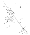
- the first embodiment for a peripheral catheter assembly which is designated in its entirety with the reference numeral 1, consists of a hollow catheter hub 2, a flexible catheter tube 3, a needle module 4 and a valve sealing 5, which fits into the catheter hub 2.
- Both the catheter tube 3, which e.g. may be of flexible polyurethane (PU), Fluorinated Ethylene Propylene copolymer FEP or poly vinyl chloride (PVC) or other suitable polymer, and the needle module 4 are known to the person skilled in the art and of substantially conventional general design.
- the hollow catheter hub 2 has a female proximal end 6 for plugging in a complementarily shaped male part, and a tapering distal end 7.
- An infusion port 8, a "chimney” merges perpendicularly into the hollow catheter hub 2 to allow fluid communication between the bore 11 of the hollow catheter hub 2 and the infusion port 8, however any angular relationship between the catheter hub 2 and the infusion port 8 is intended within the scope of the present invention.
- the infusion port 8 is shown to be closed by a pivotable flap lid 9 but closure means such as membranes or plugs are suitable alternatives.
- a Y-shaped attachment member 10 protrudes from the catheter hub 2 to provide an enlarged, flat attachment area and surface for the catheter hub 2 when the peripheral catheter assembly 1 is secured to the patients skin.
- the Y-shaped attachment member 10 can be combined with the catheter hub 2 using various means, such as adhesive substances, in particular a glue, or be moulded together with the catheter hub 2 in one single process, such as injection moulding.
- the valve sealing 5 fits intimately into the bore 11 of the catheter hub 2 between the female proximal end 6 and the distal end 7 and is, in the case shown, arranged between an annular locking ring 12 at the female proximal end and a connection piece 13 for the catheter tube 3 at the distal end 7.
- the sealing valve 5 consist of a septum seal 14 with a notch 15 and a hollow tubular extension 16 which protrudes from the septum seal 14 towards a free end 17. Both the annular locking ring 12 and the connection piece 13 can be dispensed with.
- the catheter tube 3 can be secured directly to the distal end, or even be moulded in the same process.
- the annular locking ring 12 can alternatively be made as an annular extension of the sealing valve.
- Various embodiments of sealing valve are shown and described in relation to figs. 6a,b,c .
- the needle module 4 is an obturator module consisting of a hollow needle 18, mounted in a knurled male socket 19 on a female plug 20, which may or may not provide for fluid communication between the vein and the exterior environment when fully inserted into the catheter hub 2.
- the female plug 20 is closed either by means of a removable plug or a permanent closure.
- the female plug 20 is hollow, allowing fluid communication through needle 18, male socket 19 and female plug 20.
- the cannula 18 has an upright finger press tab 21 that aids the physician in applying a controlled penetration and insertion force to the cannula 18 and serves as a grip 21 when the needle hub 4 is retracted.
- the male socket is shown to be knurled, a conventional male socket 19 having a smooth surface may also be used.
- Fig. 2 shows, seen in perspective, oblique from the top of the infusion port 8, the catheter hub 2 provided with the catheter tube 3.
- the sealing valve 5 is mounted inside the bore 11 of the catheter hub 2, between the annular locking ring 12, which is inserted in the female proximale end 6 of the catheter hub 2, and the connection piece 13, which is inserted in the distal tapering end 7 of the catheter tube 3.
- the connection piece 13 has a neck part 22 and a head part 24 both of which are mounted inside the tapering distal end 7 of the catheter hub 2.
- the head part 24 has a larger diameter than the diameter of the outlet opening of the distal end 7 of the catheter hub.
- connection piece 13 cannot be forced out of the distale end 7 of the catheter hub 2 upon manoeuvring the needle module 4.
- the exterior diameter of the neck section 22 is selected to correspond to or to be slightly larger than the diameter of the bore 23 of the catheter tube 3 to ensure firm engagement of the catheter tube 3 and secure attachment of the catheter tube 3 to the catheter hub 2.
- the female proximal end 6 of the catheter hub 2 has an internal annular relief 25 for receiving divided, deflected septum wall parts 14a,14b in response to introduction of a male socket 19, as disclosed and described in more detail with reference to fig. 4 . and fig. 5 .
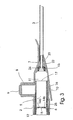
- Fig. 4 shows the needle module mounted with the male socket 19 inserted into the female proximal end 6 of the catheter hub 2.
- the male socket 19 abuts the septum seal 14 with a front end 26.
- the needle 18 has penetrated the notch 15 without substantially affecting or deflecting the septum seal 14 of the sealing valve 5. Once venipuncture has taken place the needle 18 is retracted and the septum seal wall 14a,14b self-closes to prevent blood backflow.
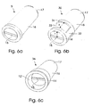
- Fig. 6a, b, and c show in perspective three embodiments of the sealing valve according to the present invention, wherein fig. 6a illustrates in enlarged scale the embodiment 5 shown in fig. 1 .
- Fig. 6b shows a second exemplary embodiment for a sealing valve 30, which corresponds substantially to the first embodiment 5 shown in fig. 6a , and for like parts same reference numerals are used.
- the second embodiment 30 differs from the first embodiment in that the tubular extension 16 is provided with an annular rib 31 and axial ribs 32, of which only one is shown in fig. 6b .
- the axial ribs 32 are provided on the exterior face of the tubular extension 16 between the septum seal 14 and the annular rib 31.
- the ribs 31,32 aids in preventing both unintended rotational and axial displacement to secure the location of the sealing valve 30 inside the catheter hub 2.
- the axial distance x between the annular rib 31 and the septum seal 14 preferably corresponds to the radius r of the deflectable walls 14a,14b, so that deflection of these walls 14a,14b remains unobstructed when the male luer connector 27 is inserted inside the female proximale end 6.
- the recessed annular section 33 of the sealing valve 30 may advantageously be used to receive complementary shaped annular protrusions 34, such as ribs 34, protruding inside the bore 11.
- the axial rib 32 may be engaged into a complementary shaped recess 35 in the interior wall of the female proximal end 6 of the catheter hub 2'.
- no locking ring 12 needs to be used because the sealing valve 30 is held engaged inside the catheter hub by means of the ribs 31,32 and recess 35.
- Fig. 6c shows a third exemplary embodiment for a sealing valve 36 which corresponds substantially to the first embodiment 5 shown in fig. 6a , and for like parts same reference numerals are used.
- the second embodiment 36 differs from the first embodiment only in that the locking ring 12' is moulded as an integrated part of the sealing valve 36, which can be inserted into the catheter hub 2 or 2' as one single unit.
- Fig. 8 shows a perspective view of the peripheral catheter assembly 1 in which the attachment member 10 is united with a plaster member 36 for adhering the peripheral catheter assembly 1 to a subjacent surface (not shown).
- the plaster member 37 is provided with an adhesive 38, which is protected by a releasable cover sheet 39.
- the plaster member 37 and the cover sheet 39 have superposing traversing apertures 40,41, respectively, for allowing the catheter tube and needle to pass through when a venipuncture is made.
- attachment member 10 is shown to be Y-shaped, any appropriate shape is intended within the scope of the present invention.
- shape can simply be squared, circular or oval.
- the sealing valve according to the present invention provides an efficient self-closing mechanism for a peripheral catheter assembly and constitutes an efficient barrier that assist in preventing contamination, e.g. due to condensation and airborne particles such as mould, spores and dust.
- the sealing valve according to the present invention makes venipuncture much easier than hitherto known, providing the physician with a freedom to leave the patient after puncture. No blood flows unintended out of the peripheral catheter when no male part is inserted into the female proximal end and nothing enters inside the body since the female proxial end of the catheter hub always is either sealed or plugged.
Claims (9)
- Eine periphere Katheteranordnung (1) mit- einem hohlen Katheterknoten (2, 2') mit einem weiblichen proximalen Ende (6) und einem distalen Ende (7), das mit einem Katheterrohr (3) versehen ist,- wenigstens einem Infusionsanschluss (8), der zwischen dem distalen Ende (7) und dem proximalen Ende (6) angeordnet ist,- einem hohlen Nadelmodul (4) mit einer Nadel (18), die von einem männlichen Sockel (19) getragen wird, der zum abdichtenden Eingreifen in das weibliche proximale Ende (6) ausgebildet ist, und- einem Dichtelement (5; 30; 36), das in das Innere des Katheterknotens (2) eingesetzt ist, wobei das Dichtelement ein Dichtventil (5; 30; 36) ist, welches- einer Septumdichtung (14) mit einem von biegbaren Septumwänden (14a, 14b), die durch das Einführen eines Gegenstands wie dem männlichen Sockel (19) oder einem männlichen Luerverbinder verbiegbar sind, umgebenen geschwächten Abschnitt (15), und- einer hohlen Rohrerstreckung (16), die in Richtung auf das freie Ende (17) von dem Umfang der Septumdichtung (14) vorragt und sich in das Innere des Katheterknotens (2) hinter dem Infusionsabschnitt (8) in Richtung auf das distale Ende (7) des Katheterknotens (2) derart erstreckt, dass ein Teil der rohrförmigen Erstreckung in Antwort auf die Fusion eines Infusionsfluids durch den Infusionsanschluss (8) zusammengedrückt werden kann,dadurch gekennzeichnet, dass der Katheterknoten (2; 2') mit einer ringförmigen Entlastung (25) zum wenigstens teilweisen Aufnehmen der verbogenen Septumdichtwand (14a, 14b) und/oder eines Teils der Wand der rohrförmigen Extension (16), die durch die verbogene Septumdichtwand (14a, 14b) verlagert ist, versehen ist.
- Eine periphere Katheteranordnung (1) nach Anspruch 1, dadurch gekennzeichnet, dass wenigstens die rohrförmige Extension (16) mit wenigstens einem Sicherungsmittel (31, 32) zum festen Sichern des Dichtventils (5, 30; 36) im Inneren des Katheterknotens (2; 2') versehen ist, um eine axiale Verlagerung des Dichtventils (5, 30; 36) zu verhindern.
- Eine periphere Katheteranordnung (1) nach Anspruch 2, dadurch gekennzeichnet, dass das Sicherungsmittel (31; 32) eine umlaufende Sicherungsrippe (31) und eine oder mehrere Verankerungsrippen (31), die sich in der axialen Richtung der rohrförmigen Erstreckung (16) zwischen der Septumdichte (14) und der umlaufenden Dichtungsrippe (31) erstrecken, wobei die Rippen (31, 32) in Eingriff mit dem weiblichen proximalen Ende (6) des Katheterknotens (2; 2') gewaltsam eingepasst sind.
- Eine periphere Katheteranordnung (1) nach einem der vorangehenden Ansprüche 1 - 3, dadurch gekennzeichnet, dass der geschwächte Abschnitt eine Kerbe (15) ist, die sich quer über die Septumdichtung (14) erstreckt.
- Eine periphere Katheteranordnung (1) nach einem der vorangehenden Ansprüche 1 - 4, dadurch gekennzeichnet, dass die periphere Katheteranordnung weiter ein hohles ringförmiges Verriegelungselement (12) mit einer ersten Endfläche, die zu der Septumdichte (14) weist, und einer gegenüberliegenden zweiten Fläche eines freien Endes einer Öffnung zum Aufnehmen eines männlichen Sockels (19) oder eines männlichen Luerkonnektors (27) aufweist.
- Eine periphere Katheteranordnung (1) nach Anspruch 5, dadurch gekennzeichnet, dass das ringförmige Verriegelungselement (12) eine Bohrung hat, die sich in Richtung auf die erste Endfläche des Verriegelungselements verjüngt.
- Eine periphere Katheteranordnung (1) nach einem der vorangehenden Ansprüche 1 - 6, dadurch gekennzeichnet, dass der Katheterknoten (2; 2') mit einem Anbringungselement (10) zum Anbringen der peripheren Katheteranordnung (1) an eine darunter liegende Fläche versehen ist.
- Eine periphere Katheteranordnung (1) nach Anspruch 7, dadurch gekennzeichnet, dass das Anbringungselement (10) mit einem Pflasterelement (37) zum Anbringen der peripheren Katheteranordnung (1) an eine darunter liegende Fläche versehen ist, wobei das Pflasterelement (37) eine Öffnung (40, 41) zum Durchlassen wenigstens des Katheterrohrs (3) hat.
- Eine periphere Katheteranordnung (1) nach einem der vorangehenden Ansprüche 1 - 8, dadurch gekennzeichnet, dass wenigstens der Katheterknoten (2; 2') transparent ist.
Priority Applications (6)
| Application Number | Priority Date | Filing Date | Title |
|---|---|---|---|
| EP07113607A EP2022421B1 (de) | 2007-08-01 | 2007-08-01 | Periphere Katheteranordnung mit Hämostasisventil |
| DE602007013746T DE602007013746D1 (de) | 2007-08-01 | 2007-08-01 | Periphere Katheteranordnung mit Hämostasisventil |
| DK07113607.1T DK2022421T3 (da) | 2007-08-01 | 2007-08-01 | Perifer kateterenhed med hæmostaseventil |
| AT07113607T ATE504248T1 (de) | 2007-08-01 | 2007-08-01 | Periphere katheteranordnung mit hämostasisventil |
| PCT/EP2008/059950 WO2009016184A1 (en) | 2007-08-01 | 2008-07-29 | A peripheral catheter assembly with haemostasis valve |
| US12/182,793 US8622972B2 (en) | 2007-08-01 | 2008-07-30 | Peripheral catheter assembly and method of using it |
Applications Claiming Priority (1)
| Application Number | Priority Date | Filing Date | Title |
|---|---|---|---|
| EP07113607A EP2022421B1 (de) | 2007-08-01 | 2007-08-01 | Periphere Katheteranordnung mit Hämostasisventil |
Publications (2)
| Publication Number | Publication Date |
|---|---|
| EP2022421A1 EP2022421A1 (de) | 2009-02-11 |
| EP2022421B1 true EP2022421B1 (de) | 2011-04-06 |
Family
ID=38617509
Family Applications (1)
| Application Number | Title | Priority Date | Filing Date |
|---|---|---|---|
| EP07113607A Active EP2022421B1 (de) | 2007-08-01 | 2007-08-01 | Periphere Katheteranordnung mit Hämostasisventil |
Country Status (6)
| Country | Link |
|---|---|
| US (1) | US8622972B2 (de) |
| EP (1) | EP2022421B1 (de) |
| AT (1) | ATE504248T1 (de) |
| DE (1) | DE602007013746D1 (de) |
| DK (1) | DK2022421T3 (de) |
| WO (1) | WO2009016184A1 (de) |
Cited By (2)
| Publication number | Priority date | Publication date | Assignee | Title |
|---|---|---|---|---|
| USD819802S1 (en) | 2016-10-05 | 2018-06-05 | Becton, Dickinson And Company | Catheter adapter |
| US11964117B2 (en) | 2019-10-14 | 2024-04-23 | Becton, Dickinson And Company | Soft push tabs for catheter adapter |
Families Citing this family (54)
| Publication number | Priority date | Publication date | Assignee | Title |
|---|---|---|---|---|
| AU2006264300B2 (en) | 2005-07-06 | 2012-03-08 | Vascular Pathways Inc. | Intravenous catheter insertion device and method of use |
| EP2272432B1 (de) | 2007-05-07 | 2012-03-14 | Vascular Pathways Inc. | Intravenöse Kathetereinführungs- und Blutprobenvorrichtung |
| EP2229975B1 (de) * | 2009-03-20 | 2013-11-13 | Tradinco AB | Einsatzanordnung für einen peripheren Katheter mit einem Pflasterelement, Verfahren zur Konfiguration der Einsetzeranordnung mit dem peripheren Katheter |
| US8323249B2 (en) | 2009-08-14 | 2012-12-04 | The Regents Of The University Of Michigan | Integrated vascular delivery system |
| JP5836931B2 (ja) * | 2010-03-26 | 2015-12-24 | テルモ株式会社 | 留置針組立体 |
| US8932258B2 (en) | 2010-05-14 | 2015-01-13 | C. R. Bard, Inc. | Catheter placement device and method |
| US9872971B2 (en) | 2010-05-14 | 2018-01-23 | C. R. Bard, Inc. | Guidewire extension system for a catheter placement device |
| US10384039B2 (en) | 2010-05-14 | 2019-08-20 | C. R. Bard, Inc. | Catheter insertion device including top-mounted advancement components |
| US9950139B2 (en) | 2010-05-14 | 2018-04-24 | C. R. Bard, Inc. | Catheter placement device including guidewire and catheter control elements |
| US11925779B2 (en) | 2010-05-14 | 2024-03-12 | C. R. Bard, Inc. | Catheter insertion device including top-mounted advancement components |
| US8771230B2 (en) | 2010-05-19 | 2014-07-08 | Tangent Medical Technologies, Llc | Integrated vascular delivery system |
| US8814833B2 (en) | 2010-05-19 | 2014-08-26 | Tangent Medical Technologies Llc | Safety needle system operable with a medical device |
| US9375551B2 (en) | 2010-09-01 | 2016-06-28 | Becton, Dickinson And Company | Neonatal and pediatric catheter system |
| US8690833B2 (en) | 2011-01-31 | 2014-04-08 | Vascular Pathways, Inc. | Intravenous catheter and insertion device with reduced blood spatter |
| WO2012154277A1 (en) | 2011-02-25 | 2012-11-15 | C.R. Bard, Inc. | Medical component insertion device including a retractable needle |
| USD903101S1 (en) | 2011-05-13 | 2020-11-24 | C. R. Bard, Inc. | Catheter |
| US9737686B2 (en) | 2012-03-12 | 2017-08-22 | Becton, Dickinson And Company | Catheter adapter port valve |
| WO2014120741A1 (en) | 2013-01-30 | 2014-08-07 | Vascular Pathways, Inc. | Systems and methods for venipuncture and catheter placement |
| JP6461174B2 (ja) | 2014-02-04 | 2019-01-30 | アイシーユー・メディカル・インコーポレーテッド | 自己プライミングシステムおよび自己プライミング方法 |
| US10232146B2 (en) | 2014-09-05 | 2019-03-19 | C. R. Bard, Inc. | Catheter insertion device including retractable needle |
| EP3028737A1 (de) | 2014-12-03 | 2016-06-08 | Tradinco AB | Selbstschließendes Katheterventil |
| USD903100S1 (en) | 2015-05-01 | 2020-11-24 | C. R. Bard, Inc. | Catheter placement device |
| SG10202006540RA (en) | 2015-05-15 | 2020-08-28 | Bard Inc C R | Catheter placement device including an extensible needle safety component |
| WO2016185950A1 (ja) | 2015-05-15 | 2016-11-24 | テルモ株式会社 | カテーテル組立体 |
| MY193679A (en) | 2015-08-18 | 2022-10-25 | Braun Melsungen Ag | Catheter devices with valves and related methods |
| US10639455B2 (en) | 2015-10-28 | 2020-05-05 | Becton, Dickinson And Company | Closed IV access device with paddle grip needle hub and flash chamber |
| US10525237B2 (en) | 2015-10-28 | 2020-01-07 | Becton, Dickinson And Company | Ergonomic IV systems and methods |
| US10814106B2 (en) | 2015-10-28 | 2020-10-27 | Becton, Dickinson And Company | Soft push tabs for catheter adapter |
| US10245416B2 (en) | 2015-10-28 | 2019-04-02 | Becton, Dickinson And Company | Intravenous catheter device with integrated extension tube |
| US10744305B2 (en) | 2015-10-28 | 2020-08-18 | Becton, Dickinson And Company | Ergonomic IV systems and methods |
| US10549072B2 (en) | 2015-10-28 | 2020-02-04 | Becton, Dickinson And Company | Integrated catheter with independent fluid paths |
| US10357636B2 (en) | 2015-10-28 | 2019-07-23 | Becton, Dickinson And Company | IV access device having an angled paddle grip |
| USD783162S1 (en) * | 2016-04-19 | 2017-04-04 | Avent, Inc. | Finger tab |
| USD783161S1 (en) * | 2016-04-19 | 2017-04-04 | Avent, Inc. | Catheter connector surface |
| USD783160S1 (en) * | 2016-04-19 | 2017-04-04 | Avent, Inc. | Catheter connector |
| USD783163S1 (en) * | 2016-04-19 | 2017-04-04 | Avent, Inc. | Finger tabs |
| WO2018049413A1 (en) | 2016-09-12 | 2018-03-15 | C.R. Bard, Inc. | Blood control for a catheter insertion device |
| USD835262S1 (en) | 2016-10-05 | 2018-12-04 | Becton, Dickinson And Company | Intravenous catheter assembly |
| US10238852B2 (en) | 2016-10-05 | 2019-03-26 | Becton, Dickinson And Company | Septum housing |
| USD844781S1 (en) | 2016-10-05 | 2019-04-02 | Becton, Dickinson And Company | Needle hub |
| USD837368S1 (en) | 2016-10-05 | 2019-01-01 | Becton, Dickinson And Company | Catheter adapter grip |
| US11400260B2 (en) | 2017-03-01 | 2022-08-02 | C. R. Bard, Inc. | Catheter insertion device |
| EP3503957B1 (de) | 2017-03-24 | 2023-10-25 | Poly Medicure Limited | Intravenöse katheteranordnung |
| US11207501B2 (en) | 2017-05-30 | 2021-12-28 | Velano Vascular, Inc. | Stabilization devices for vascular access and methods of using the same |
| US11191939B2 (en) | 2017-11-30 | 2021-12-07 | Velano Vascular, Inc. | Stabilizing connector devices for vascular access and methods of using the same |
| CN115671504A (zh) | 2018-03-07 | 2023-02-03 | 巴德阿克塞斯系统股份有限公司 | 用于医疗装置插入系统的导丝推进和血液闪回系统 |
| USD921884S1 (en) | 2018-07-27 | 2021-06-08 | Bard Access Systems, Inc. | Catheter insertion device |
| JP2022502132A (ja) | 2018-09-28 | 2022-01-11 | ベラノ バスキュラー,インコーポレイテッド | 閉鎖系静脈内カテーテルによる静脈穿刺のためのデバイス及び方法 |
| WO2020127328A1 (en) | 2018-12-17 | 2020-06-25 | B. Braun Melsungen Ag | Over-the-needle catheter assemblies and related manufacturing method |
| CN112043904A (zh) * | 2019-06-06 | 2020-12-08 | 曾凡洪 | 静脉导管封堵器 |
| CN112386778A (zh) | 2019-08-19 | 2021-02-23 | 贝克顿·迪金森公司 | 中线导管放置装置 |
| US20220226631A1 (en) * | 2021-01-20 | 2022-07-21 | Becton, Dickinson And Company | Valve retainer ring and related systems and methods |
| WO2022251015A1 (en) * | 2021-05-27 | 2022-12-01 | Becton, Dickinson And Company | Retainer element to secure a catheter adapter valve |
| US20230140352A1 (en) * | 2021-10-28 | 2023-05-04 | Biosense Webster (Israel) Ltd. | Sheath valve housing |
Family Cites Families (15)
| Publication number | Priority date | Publication date | Assignee | Title |
|---|---|---|---|---|
| US4929235A (en) * | 1985-07-31 | 1990-05-29 | Universal Medical Instrument Corp. | Self-sealing percutaneous tube introducer |
| GB8627808D0 (en) * | 1986-11-20 | 1986-12-17 | Cox J A | Sampling liquids from human/animal body |
| US5000745A (en) * | 1988-11-18 | 1991-03-19 | Edward Weck Incorporated | Hemostatis valve |
| US5041097A (en) * | 1990-02-26 | 1991-08-20 | Johnson Gerald W | Intravenous catheter fitting with protective end seal |
| US5098405A (en) * | 1991-01-31 | 1992-03-24 | Becton, Dickinson And Company | Apparatus and method for a side port cathether adapter with a one piece integral combination valve |
| US5599305A (en) * | 1994-10-24 | 1997-02-04 | Cardiovascular Concepts, Inc. | Large-diameter introducer sheath having hemostasis valve and removable steering mechanism |
| US6053861A (en) * | 1998-05-11 | 2000-04-25 | Circon Corporation | Self-closing seal for a medical instrument |
| US6213978B1 (en) | 1998-10-27 | 2001-04-10 | Cherie A. Voyten | Intravenous catheter insertion apparatus |
| US6485473B1 (en) * | 1999-08-12 | 2002-11-26 | Lawrence A. Lynn | Luer receiving vascular access system |
| JP2001185804A (ja) * | 1999-12-27 | 2001-07-06 | Asahi Optical Co Ltd | 半導体レーザ装置 |
| US7083598B2 (en) * | 2002-08-27 | 2006-08-01 | Jan Liska | Transcutan catheter assembly |
| FR2867081B1 (fr) * | 2004-03-02 | 2006-05-26 | Vygon | Dispositif a organe de securite coulissant pour la mise en place d'une canule dans une veine |
| WO2007028200A1 (en) * | 2005-09-07 | 2007-03-15 | Hamish Meares | Securing device for cannulas |
| DE202007006190U1 (de) * | 2006-07-31 | 2007-08-23 | B. Braun Melsungen Ag | Kathetervorrichtung |
| US8257313B2 (en) * | 2006-08-11 | 2012-09-04 | Becton, Dickinson And Company | Integrated septum and needle tip shield for a catheter assembly |
-
2007
- 2007-08-01 EP EP07113607A patent/EP2022421B1/de active Active
- 2007-08-01 AT AT07113607T patent/ATE504248T1/de not_active IP Right Cessation
- 2007-08-01 DE DE602007013746T patent/DE602007013746D1/de active Active
- 2007-08-01 DK DK07113607.1T patent/DK2022421T3/da active
-
2008
- 2008-07-29 WO PCT/EP2008/059950 patent/WO2009016184A1/en active Application Filing
- 2008-07-30 US US12/182,793 patent/US8622972B2/en active Active
Cited By (3)
| Publication number | Priority date | Publication date | Assignee | Title |
|---|---|---|---|---|
| USD819802S1 (en) | 2016-10-05 | 2018-06-05 | Becton, Dickinson And Company | Catheter adapter |
| USD900308S1 (en) | 2016-10-05 | 2020-10-27 | Becton, Dickinson And Company | Catheter adapter |
| US11964117B2 (en) | 2019-10-14 | 2024-04-23 | Becton, Dickinson And Company | Soft push tabs for catheter adapter |
Also Published As
| Publication number | Publication date |
|---|---|
| WO2009016184A1 (en) | 2009-02-05 |
| DE602007013746D1 (de) | 2011-05-19 |
| US8622972B2 (en) | 2014-01-07 |
| US20090036836A1 (en) | 2009-02-05 |
| DK2022421T3 (da) | 2011-07-18 |
| ATE504248T1 (de) | 2011-04-15 |
| EP2022421A1 (de) | 2009-02-11 |
Similar Documents
| Publication | Publication Date | Title |
|---|---|---|
| EP2022421B1 (de) | Periphere Katheteranordnung mit Hämostasisventil | |
| US20220233817A1 (en) | Catheter adapter port valve | |
| US6699221B2 (en) | Bloodless catheter | |
| US5154703A (en) | Bloodless catheter | |
| EP3416714B1 (de) | Katheter mit geschlossenem system | |
| EP2763737B1 (de) | Aktivatorbefestigung für blutkontrollkatheter | |
| US20160220805A1 (en) | Intravenous catheter assembly design | |
| EP0440479B1 (de) | Katheter mit angesteuertem Ventil | |
| EP3632502B1 (de) | Rotationsaktivierte blutkontrolle | |
| EP1466645B1 (de) | Medizintechnischer Verbindersatz und Verweilkatheter | |
| ES2215359T3 (es) | Procedimiento de transferencia de fluido. | |
| EP3481489A1 (de) | Entlüftungskappe für katheter mit geschlossenem system | |
| EP3384954B1 (de) | Infusionssysteme, anschlüsse zur verwendung mit kathetervorrichtungen und zugehörige verfahren | |
| US20160361490A1 (en) | Safety needle assemblies and related methods | |
| US8192404B2 (en) | Indwelling needle assembly | |
| NO314245B1 (no) | Medisinsk ventil med fluidunnslippelsesrom | |
| JP2008513119A (ja) | 成形エラストマー先端を有するセルフシール雄ルアーコネクタ | |
| NO314246B1 (no) | Medisinsk ventil med ringtetning og fremgangsmåten for overföring av et fluid gjennom en medisinsk ventil | |
| GB2508570A (en) | Needle guard for a catheter assembly | |
| AU2012318627A1 (en) | An intravenous catheter with duckbill valve | |
| US20170319822A1 (en) | Intravenous Catheter Assembly | |
| US6491668B1 (en) | Needleless fluid transfer | |
| CN114364428A (zh) | 血管接入装置适配器 | |
| US20230310801A1 (en) | Closed system catheter |
Legal Events
| Date | Code | Title | Description |
|---|---|---|---|
| PUAI | Public reference made under article 153(3) epc to a published international application that has entered the european phase |
Free format text: ORIGINAL CODE: 0009012 |
|
| AK | Designated contracting states |
Kind code of ref document: A1 Designated state(s): AT BE BG CH CY CZ DE DK EE ES FI FR GB GR HU IE IS IT LI LT LU LV MC MT NL PL PT RO SE SI SK TR |
|
| AX | Request for extension of the european patent |
Extension state: AL BA HR MK RS |
|
| 17P | Request for examination filed |
Effective date: 20090811 |
|
| 17Q | First examination report despatched |
Effective date: 20090907 |
|
| AKX | Designation fees paid |
Designated state(s): AT BE BG CH CY CZ DE DK EE ES FI FR GB GR HU IE IS IT LI LT LU LV MC MT NL PL PT RO SE SI SK TR |
|
| GRAP | Despatch of communication of intention to grant a patent |
Free format text: ORIGINAL CODE: EPIDOSNIGR1 |
|
| GRAC | Information related to communication of intention to grant a patent modified |
Free format text: ORIGINAL CODE: EPIDOSCIGR1 |
|
| GRAS | Grant fee paid |
Free format text: ORIGINAL CODE: EPIDOSNIGR3 |
|
| GRAA | (expected) grant |
Free format text: ORIGINAL CODE: 0009210 |
|
| AK | Designated contracting states |
Kind code of ref document: B1 Designated state(s): AT BE BG CH CY CZ DE DK EE ES FI FR GB GR HU IE IS IT LI LT LU LV MC MT NL PL PT RO SE SI SK TR |
|
| REG | Reference to a national code |
Ref country code: GB Ref legal event code: FG4D |
|
| REG | Reference to a national code |
Ref country code: CH Ref legal event code: EP |
|
| REG | Reference to a national code |
Ref country code: IE Ref legal event code: FG4D |
|
| REF | Corresponds to: |
Ref document number: 602007013746 Country of ref document: DE Date of ref document: 20110519 Kind code of ref document: P |
|
| REG | Reference to a national code |
Ref country code: DE Ref legal event code: R096 Ref document number: 602007013746 Country of ref document: DE Effective date: 20110519 |
|
| REG | Reference to a national code |
Ref country code: CH Ref legal event code: NV Representative=s name: JACOBACCI & PARTNERS S.P.A. |
|
| REG | Reference to a national code |
Ref country code: DK Ref legal event code: T3 |
|
| REG | Reference to a national code |
Ref country code: SE Ref legal event code: TRGR |
|
| REG | Reference to a national code |
Ref country code: NL Ref legal event code: VDEP Effective date: 20110406 |
|
| PG25 | Lapsed in a contracting state [announced via postgrant information from national office to epo] |
Ref country code: SI Free format text: LAPSE BECAUSE OF FAILURE TO SUBMIT A TRANSLATION OF THE DESCRIPTION OR TO PAY THE FEE WITHIN THE PRESCRIBED TIME-LIMIT Effective date: 20110406 |
|
| LTIE | Lt: invalidation of european patent or patent extension |
Effective date: 20110406 |
|
| PG25 | Lapsed in a contracting state [announced via postgrant information from national office to epo] |
Ref country code: PT Free format text: LAPSE BECAUSE OF FAILURE TO SUBMIT A TRANSLATION OF THE DESCRIPTION OR TO PAY THE FEE WITHIN THE PRESCRIBED TIME-LIMIT Effective date: 20110808 Ref country code: LT Free format text: LAPSE BECAUSE OF FAILURE TO SUBMIT A TRANSLATION OF THE DESCRIPTION OR TO PAY THE FEE WITHIN THE PRESCRIBED TIME-LIMIT Effective date: 20110406 |
|
| PGFP | Annual fee paid to national office [announced via postgrant information from national office to epo] |
Ref country code: CH Payment date: 20110708 Year of fee payment: 5 Ref country code: IE Payment date: 20110712 Year of fee payment: 5 Ref country code: DK Payment date: 20110712 Year of fee payment: 5 |
|
| PG25 | Lapsed in a contracting state [announced via postgrant information from national office to epo] |
Ref country code: GR Free format text: LAPSE BECAUSE OF FAILURE TO SUBMIT A TRANSLATION OF THE DESCRIPTION OR TO PAY THE FEE WITHIN THE PRESCRIBED TIME-LIMIT Effective date: 20110707 Ref country code: CY Free format text: LAPSE BECAUSE OF FAILURE TO SUBMIT A TRANSLATION OF THE DESCRIPTION OR TO PAY THE FEE WITHIN THE PRESCRIBED TIME-LIMIT Effective date: 20110406 Ref country code: BE Free format text: LAPSE BECAUSE OF FAILURE TO SUBMIT A TRANSLATION OF THE DESCRIPTION OR TO PAY THE FEE WITHIN THE PRESCRIBED TIME-LIMIT Effective date: 20110406 Ref country code: ES Free format text: LAPSE BECAUSE OF FAILURE TO SUBMIT A TRANSLATION OF THE DESCRIPTION OR TO PAY THE FEE WITHIN THE PRESCRIBED TIME-LIMIT Effective date: 20110717 Ref country code: IS Free format text: LAPSE BECAUSE OF FAILURE TO SUBMIT A TRANSLATION OF THE DESCRIPTION OR TO PAY THE FEE WITHIN THE PRESCRIBED TIME-LIMIT Effective date: 20110806 Ref country code: FI Free format text: LAPSE BECAUSE OF FAILURE TO SUBMIT A TRANSLATION OF THE DESCRIPTION OR TO PAY THE FEE WITHIN THE PRESCRIBED TIME-LIMIT Effective date: 20110406 Ref country code: LV Free format text: LAPSE BECAUSE OF FAILURE TO SUBMIT A TRANSLATION OF THE DESCRIPTION OR TO PAY THE FEE WITHIN THE PRESCRIBED TIME-LIMIT Effective date: 20110406 Ref country code: AT Free format text: LAPSE BECAUSE OF FAILURE TO SUBMIT A TRANSLATION OF THE DESCRIPTION OR TO PAY THE FEE WITHIN THE PRESCRIBED TIME-LIMIT Effective date: 20110406 |
|
| PG25 | Lapsed in a contracting state [announced via postgrant information from national office to epo] |
Ref country code: MT Free format text: LAPSE BECAUSE OF FAILURE TO SUBMIT A TRANSLATION OF THE DESCRIPTION OR TO PAY THE FEE WITHIN THE PRESCRIBED TIME-LIMIT Effective date: 20110406 Ref country code: NL Free format text: LAPSE BECAUSE OF FAILURE TO SUBMIT A TRANSLATION OF THE DESCRIPTION OR TO PAY THE FEE WITHIN THE PRESCRIBED TIME-LIMIT Effective date: 20110406 |
|
| PG25 | Lapsed in a contracting state [announced via postgrant information from national office to epo] |
Ref country code: CZ Free format text: LAPSE BECAUSE OF FAILURE TO SUBMIT A TRANSLATION OF THE DESCRIPTION OR TO PAY THE FEE WITHIN THE PRESCRIBED TIME-LIMIT Effective date: 20110406 Ref country code: EE Free format text: LAPSE BECAUSE OF FAILURE TO SUBMIT A TRANSLATION OF THE DESCRIPTION OR TO PAY THE FEE WITHIN THE PRESCRIBED TIME-LIMIT Effective date: 20110406 |
|
| PLBE | No opposition filed within time limit |
Free format text: ORIGINAL CODE: 0009261 |
|
| STAA | Information on the status of an ep patent application or granted ep patent |
Free format text: STATUS: NO OPPOSITION FILED WITHIN TIME LIMIT |
|
| PG25 | Lapsed in a contracting state [announced via postgrant information from national office to epo] |
Ref country code: RO Free format text: LAPSE BECAUSE OF FAILURE TO SUBMIT A TRANSLATION OF THE DESCRIPTION OR TO PAY THE FEE WITHIN THE PRESCRIBED TIME-LIMIT Effective date: 20110406 Ref country code: PL Free format text: LAPSE BECAUSE OF FAILURE TO SUBMIT A TRANSLATION OF THE DESCRIPTION OR TO PAY THE FEE WITHIN THE PRESCRIBED TIME-LIMIT Effective date: 20110406 Ref country code: SK Free format text: LAPSE BECAUSE OF FAILURE TO SUBMIT A TRANSLATION OF THE DESCRIPTION OR TO PAY THE FEE WITHIN THE PRESCRIBED TIME-LIMIT Effective date: 20110406 |
|
| 26N | No opposition filed |
Effective date: 20120110 |
|
| PG25 | Lapsed in a contracting state [announced via postgrant information from national office to epo] |
Ref country code: MC Free format text: LAPSE BECAUSE OF NON-PAYMENT OF DUE FEES Effective date: 20110831 |
|
| REG | Reference to a national code |
Ref country code: DE Ref legal event code: R097 Ref document number: 602007013746 Country of ref document: DE Effective date: 20120110 |
|
| REG | Reference to a national code |
Ref country code: CH Ref legal event code: PL |
|
| REG | Reference to a national code |
Ref country code: DK Ref legal event code: EBP |
|
| PG25 | Lapsed in a contracting state [announced via postgrant information from national office to epo] |
Ref country code: LI Free format text: LAPSE BECAUSE OF NON-PAYMENT OF DUE FEES Effective date: 20120831 Ref country code: CH Free format text: LAPSE BECAUSE OF NON-PAYMENT OF DUE FEES Effective date: 20120831 |
|
| REG | Reference to a national code |
Ref country code: IE Ref legal event code: MM4A |
|
| PG25 | Lapsed in a contracting state [announced via postgrant information from national office to epo] |
Ref country code: LU Free format text: LAPSE BECAUSE OF NON-PAYMENT OF DUE FEES Effective date: 20110801 |
|
| PG25 | Lapsed in a contracting state [announced via postgrant information from national office to epo] |
Ref country code: BG Free format text: LAPSE BECAUSE OF FAILURE TO SUBMIT A TRANSLATION OF THE DESCRIPTION OR TO PAY THE FEE WITHIN THE PRESCRIBED TIME-LIMIT Effective date: 20110706 |
|
| PG25 | Lapsed in a contracting state [announced via postgrant information from national office to epo] |
Ref country code: IE Free format text: LAPSE BECAUSE OF NON-PAYMENT OF DUE FEES Effective date: 20120801 Ref country code: DK Free format text: LAPSE BECAUSE OF NON-PAYMENT OF DUE FEES Effective date: 20120831 |
|
| PG25 | Lapsed in a contracting state [announced via postgrant information from national office to epo] |
Ref country code: TR Free format text: LAPSE BECAUSE OF FAILURE TO SUBMIT A TRANSLATION OF THE DESCRIPTION OR TO PAY THE FEE WITHIN THE PRESCRIBED TIME-LIMIT Effective date: 20110406 |
|
| PG25 | Lapsed in a contracting state [announced via postgrant information from national office to epo] |
Ref country code: HU Free format text: LAPSE BECAUSE OF FAILURE TO SUBMIT A TRANSLATION OF THE DESCRIPTION OR TO PAY THE FEE WITHIN THE PRESCRIBED TIME-LIMIT Effective date: 20110406 |
|
| PG25 | Lapsed in a contracting state [announced via postgrant information from national office to epo] |
Ref country code: IT Free format text: LAPSE BECAUSE OF FAILURE TO SUBMIT A TRANSLATION OF THE DESCRIPTION OR TO PAY THE FEE WITHIN THE PRESCRIBED TIME-LIMIT Effective date: 20110406 |
|
| REG | Reference to a national code |
Ref country code: FR Ref legal event code: PLFP Year of fee payment: 10 |
|
| PGFP | Annual fee paid to national office [announced via postgrant information from national office to epo] |
Ref country code: SE Payment date: 20160815 Year of fee payment: 10 |
|
| REG | Reference to a national code |
Ref country code: FR Ref legal event code: PLFP Year of fee payment: 11 |
|
| PG25 | Lapsed in a contracting state [announced via postgrant information from national office to epo] |
Ref country code: SE Free format text: LAPSE BECAUSE OF NON-PAYMENT OF DUE FEES Effective date: 20170802 |
|
| REG | Reference to a national code |
Ref country code: FR Ref legal event code: PLFP Year of fee payment: 12 |
|
| PGFP | Annual fee paid to national office [announced via postgrant information from national office to epo] |
Ref country code: GB Payment date: 20220823 Year of fee payment: 16 |
|
| PGFP | Annual fee paid to national office [announced via postgrant information from national office to epo] |
Ref country code: FR Payment date: 20220823 Year of fee payment: 16 |
|
| PGFP | Annual fee paid to national office [announced via postgrant information from national office to epo] |
Ref country code: DE Payment date: 20230818 Year of fee payment: 17 |