EP2021758B1 - Elastic joint with a translating spherical hinge and force and moment sensor improved by means of the said joint - Google Patents
Elastic joint with a translating spherical hinge and force and moment sensor improved by means of the said joint Download PDFInfo
- Publication number
- EP2021758B1 EP2021758B1 EP07734641.9A EP07734641A EP2021758B1 EP 2021758 B1 EP2021758 B1 EP 2021758B1 EP 07734641 A EP07734641 A EP 07734641A EP 2021758 B1 EP2021758 B1 EP 2021758B1
- Authority
- EP
- European Patent Office
- Prior art keywords
- elastic
- joint
- measuring
- spherical hinge
- plane
- Prior art date
- Legal status (The legal status is an assumption and is not a legal conclusion. Google has not performed a legal analysis and makes no representation as to the accuracy of the status listed.)
- Active
Links
Images


Classifications
-
- G—PHYSICS
- G01—MEASURING; TESTING
- G01L—MEASURING FORCE, STRESS, TORQUE, WORK, MECHANICAL POWER, MECHANICAL EFFICIENCY, OR FLUID PRESSURE
- G01L3/00—Measuring torque, work, mechanical power, or mechanical efficiency, in general
- G01L3/16—Rotary-absorption dynamometers, e.g. of brake type
- G01L3/22—Rotary-absorption dynamometers, e.g. of brake type electrically or magnetically actuated
-
- Y—GENERAL TAGGING OF NEW TECHNOLOGICAL DEVELOPMENTS; GENERAL TAGGING OF CROSS-SECTIONAL TECHNOLOGIES SPANNING OVER SEVERAL SECTIONS OF THE IPC; TECHNICAL SUBJECTS COVERED BY FORMER USPC CROSS-REFERENCE ART COLLECTIONS [XRACs] AND DIGESTS
- Y10—TECHNICAL SUBJECTS COVERED BY FORMER USPC
- Y10T—TECHNICAL SUBJECTS COVERED BY FORMER US CLASSIFICATION
- Y10T403/00—Joints and connections
- Y10T403/32—Articulated members
- Y10T403/32549—Articulated members including limit means
- Y10T403/32557—Articulated members including limit means for pivotal motion
Definitions
- the present invention relates to a force and moment sensor improved by means of an elastic joint with a translating spherical hinge.
- Rigid sensors can be used, for example, positioned between the elements which exchange forces, or sensors comprising a measuring structure constrained in a statically determined way to the body whose stress is to be measured.
- the sensor consists, for example, of a measuring structure comprising, in the central part, three arms, in which each arm is constrained to the supports connected to the body whose stress is to be measured by means of a joint consisting of a spherical translating hinge, i.e. a spherical hinge and a sliding joint.
- a spherical translating hinge i.e. a spherical hinge and a sliding joint.
- Each translating spherical hinge has only two constraint degrees, allowing, in fact, four degrees of freedom, i.e. one degree of freedom for translation in a plane orthogonal to the constraint plane mentioned above, one degree of freedom for torsion and two degrees of freedom with respect to rotations.
- the translating spherical hinges of the known type can, for example, be produced by combining with each other, in series, a spherical joint and a translating sleeve. These hinges however are subject to the friction, due to the use of smooth or ball bearings, which jeopardizes the sensitivity and accuracy of the measurements (see WO 2005/015146 ).
- An objective of the present invention is to provide a force and moment sensor improved by means of an elastic joint with a translating spherical hinge, which solve the above-mentioned drawbacks.
- Another objective of the present invention is to provide an accurate and sensitive force and moment sensor.
- Yet another objective of the present invention is to provide an improved force and moment sensor with an elastic joint with a translating spherical hinge which is particularly simple and functional, with reduced costs.
- a structure can be obtained wherein a vertical rod 14 can translate along its own axis 11 and spherically rotate around the central hinge.
- Horizontal elastic elements 12 are suitably stretched wires, or beams with constraints 15 at the ends, consisting of hinges (generally spherical hinges).
- This structure is four times unstable and, in addition to the three spatial rotations of the vertical rod 14, it also allows the small movement in a vertical direction of the same vertical rod 14.
- This structure can function with a number of wires or beams 12, higher or equal to three. With two wires or beams 12, in fact, it does not function properly as there is a fragility in the orthogonal direction with respect to the axes of the two beams, or wires 12, and lying in an horizontal plane 13 which contains the two beams or wires 12.
- Figures 4, 5 and 6 illustrate an elastic joint, having a translating spherical hinge, indicated as a whole with 10, and two different embodiments of a force and moment sensor, indicated as a whole with 100, improved by means of the said joint 10.
- the elastic joint with a translating spherical hinge 10, or the joint of the type with the spherical hinge with a sliding joint, is particularly suitable for being used in the force and moment sensor 100 which, in the example, comprises a three-armed measuring structure 102, connected by means of three joints 10 to a body 101 to which forces and moments to be measured are applied.
- the elastic joint with a translating spherical hinge 10, comprises a series of elastic elements 12, or at least three beams or two elastic laminae 12, positioned in a first horizontal plane with a first end facing so as to form the articulation elastic plane 13.
- the facing ends of the elastic elements 12 are rigidly connected to an axial rod element 14 arranged according to the axis 11 orthogonal to the articulation elastic plane 13.
- a series of beams 12 are uniformly distributed in the horizontal plane 13, equidistanced between each other, or comprising equal angles between each other.
- the beams 12 are connected to a rigid support 16, constrainable to the body 101 by means of a dap joint 15 ( figure 5 ).
- the beams 12 are flexible in any vertical plane comprising the orthogonal axis 11 and in the horizontal plane 13.
- the articulation of the joint 10 takes place between the axial element 14 and the support 16 and allows four degrees of freedom, i.e. the translation of the axial element 14 in the direction of the orthogonal axis 11 and the spatial rotation of the axial element 14, by means of flexure of the elastic elements 12 in any vertical plane comprising the orthogonal axis 11, as well as the torsion of the axial element 14 around the same axis 11, by means of flexure of the elastic elements 12 in the horizontal plane 13, respectively.
- the beams 12 situated in the horizontal plane 13, equidistanced between each other, can consist of two aligned laminae 12, having an extension in the articulation elastic plane 13 much greater than their thickness, as shown in figure 7 .
- the elastic elements 12, shown and described, can be made of different materials, for example, the wires 12 in figure 1 can be made with steel wires or Kevlar filaments, or different material, and immersed in a resin matrix.
- the beams or laminae 12 can be made of various materials, such as steel, plastic or composite material. The selection of the material, thickness and width is effected with the intent of optimizing the ratio between the rigidities.
- the elastic joint with a translating elastic hinge 10, according to the present invention constrains the axial element 14 and gives it a high rigidity with respect to the movements in the plane 13.
- the axial element 14, on the contrary, has an axially pliable behaviour, i.e. in the direction of the axis 11 and, due to the effect of the elastic elements 12, also the possibility of performing a spherical rotation.
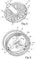
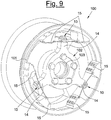
- the force and moment sensor 100 with the elastic joint with a translating spherical hinge is shown in figures 5 , 6 , and 9 .
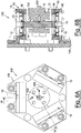
- the sensor 100 comprises the three-arm measuring structure 102 ( figure 8 ) connected to the body 101, to which forces and moments to be measured are applied by means of three elastic joints with a translating spherical hinge 10.
- the measuring structure of figure 8 is assembled as a dynamometric hub centred on a hub 103 of a wheel 101 and the arms, or an extension of the same, represent the axial element 14 of the joint 10.
- the support 16 of the joint 10 is rigidly connected to the body 101, in the example to the wheel rim, by a constraint of the dap joint type 15.
- Figures 6A and 6B show a further force and moment sensor 100 improved by means of an elastic joint with a translating spherical hinge, object of the present invention, for use as a static force and moment sensor.
- the sensor 100 of figures 6A and 6B does in fact allow the forces to be measured which are exchanged between a first supporting element 101 to which the joints 10 are constrained and a second axial element 103, integral with the measuring structure 102.
- the measuring structure 102 is statically determined and is equipped with means for the measuring 104 of six stress magnitudes from which the force and moment vectors acting on the body 101 can be mathematically obtained.
- the six magnitudes are revealed on the arms of the measuring structure 102.
- Each arm is in fact subjected to stress along its own length by two orthogonal flexing moments.
- the two stress flexures which are exerted by the above two orthogonal flexing moments, can be measured by two pairs of strain gauges applied on opposite sides of the arms themselves, as schematically shown in figure 8 , in which 1a, 1b, 2a, 2b, 3a, 3b, 4a, 4b, 5a, 5b, 6a and 6b indicate six pairs of strain gauges which form an example of possible measuring means.
- the elastic joint with a translating spherical hinge 10 comprises two aligned laminae 12 having extension in the elastic articulation plane 13, according to what is illustrated in figure 7 .
- Figure 10 schematically shows the positioning of two pairs of strain gauges 1'a, 1'b, 2'a, 2'b on the two aligned laminae 12, for measuring the constraint reaction acting in a lateral direction and for measuring the constraint reaction acting in a longitudinal direction on the laminae 12, respectively.
- measuring means 104 which can be used for measuring the flexure are, for example, movement sensors which reveal the movements of the laminae 12, directly applied to the laminae 12.
- a force vector F is univocally obtained, dissembled into three vectors directed along three coordinated axes and a moment vector T dissembled into three vectors directed along three coordinated axes, i.e. the six generalized forces acting on the body.
- measuring means 104 which can be used are piezoelectric elements or elements of another kind, not shown, which can be positioned between the end of each of the three arms of the measuring structure 102 and each of the relative joints with a translating spherical hinge 10. These measuring means are capable of measuring two forces orthogonal with respect to the axis 11 and orthogonal with respect to each other and mathematically obtaining the force F and moment T vectors acting on the body 101.
- the use of silicon, or another similar technology allows the production of an elastic joint with a translating spherical hinge 10 and a relative sensor 100 in nanoscale, i.e. with minimum dimensions.
- this shows a last embodiment of a force and moment sensor 100 produced as a dynamometric hub, in which each translating spherical hinge 10 is produced integrally with the measuring structure 102 and with the same rim channel 101 as a road or off-road vehicle forming a single structure.
- This rim is extremely economical as it provides localized deformation areas which allow the acting forces and moments to be surveyed, at substantially the same cost as a normal rim.
- the elastic joint with a translating spherical hinge has the advantage of eliminating the problem of friction.
- the elastic joint with a translating spherical hinge also allows the force and moment sensor to be improved, allowing optimum performances, which are more accurate and sensitive, on the part of the sensor, in addition to a relatively economical construction cost.
- the sensor improved by means of the elastic joint with a translating hinge is also suitable for the production of an extremely precise and low-cost dynamometric hub with the possibility of generalized use on vehicles.
Landscapes
- Physics & Mathematics (AREA)
- General Physics & Mathematics (AREA)
- Force Measurement Appropriate To Specific Purposes (AREA)
- Pivots And Pivotal Connections (AREA)
- Golf Clubs (AREA)
Applications Claiming Priority (2)
| Application Number | Priority Date | Filing Date | Title |
|---|---|---|---|
| IT001000A ITMI20061000A1 (it) | 2006-05-22 | 2006-05-22 | Giunto elastico a cerniera sferica traslante e sensore di forze e momenti perfezionato con tale giunto |
| PCT/IB2007/001335 WO2007135551A2 (en) | 2006-05-22 | 2007-05-16 | Elastic joint with a translating spherical hinge and force and moment sensor improved by means of the said joint |
Publications (2)
| Publication Number | Publication Date |
|---|---|
| EP2021758A2 EP2021758A2 (en) | 2009-02-11 |
| EP2021758B1 true EP2021758B1 (en) | 2019-04-10 |
Family
ID=38723673
Family Applications (1)
| Application Number | Title | Priority Date | Filing Date |
|---|---|---|---|
| EP07734641.9A Active EP2021758B1 (en) | 2006-05-22 | 2007-05-16 | Elastic joint with a translating spherical hinge and force and moment sensor improved by means of the said joint |
Country Status (5)
| Country | Link |
|---|---|
| US (1) | US7779705B2 (enExample) |
| EP (1) | EP2021758B1 (enExample) |
| JP (1) | JP2009537771A (enExample) |
| IT (1) | ITMI20061000A1 (enExample) |
| WO (1) | WO2007135551A2 (enExample) |
Families Citing this family (27)
| Publication number | Priority date | Publication date | Assignee | Title |
|---|---|---|---|---|
| ITMI20031500A1 (it) * | 2003-07-22 | 2005-01-23 | Milano Politecnico | Dispositivo e metodo per la misura di forze e momenti |
| US7272976B2 (en) * | 2004-03-30 | 2007-09-25 | Asml Holdings N.V. | Pressure sensor |
| US8496647B2 (en) | 2007-12-18 | 2013-07-30 | Intuitive Surgical Operations, Inc. | Ribbed force sensor |
| US8561473B2 (en) | 2007-12-18 | 2013-10-22 | Intuitive Surgical Operations, Inc. | Force sensor temperature compensation |
| US8657376B2 (en) * | 2008-10-11 | 2014-02-25 | D-Box Technologies Inc. | Link member for motion-enabled movie theatre chair |
| US8270169B2 (en) | 2009-03-24 | 2012-09-18 | Raytheon Company | Translating hinge |
| KR101115418B1 (ko) * | 2009-11-09 | 2012-02-16 | 한국표준과학연구원 | 힘센서를 이용한 6축 힘센서 구조 및 그 구조에 의한 힘 및 모멘트 측정방법 |
| CN102501247B (zh) * | 2011-11-08 | 2014-01-08 | 湖南大学 | 全柔性六自由度细微操作平台 |
| CN103076126B (zh) * | 2012-12-27 | 2014-10-15 | 上海交通大学 | 一种基于柔性铰链的电机力矩测定装置及方法 |
| EP3425362B1 (en) | 2013-03-12 | 2020-12-09 | Stryker Corporation | Sensor assembly and method for measuring forces and torques |
| US9993309B2 (en) * | 2015-02-03 | 2018-06-12 | Stryker Corporation | Force/torque transducer and method of operating the same |
| EP3165470A1 (en) * | 2015-11-06 | 2017-05-10 | Almatech Sarl | Large angle flexible pivot |
| CN105334042B (zh) * | 2015-12-08 | 2017-09-29 | 济南瑞晟机械有限公司 | 一种电液伺服转向球铰疲劳试验机 |
| US10295418B1 (en) * | 2016-03-29 | 2019-05-21 | X Development Llc | Factory-calibrated multi-spoke strain sensor system |
| JP6407948B2 (ja) | 2016-12-21 | 2018-10-17 | ファナック株式会社 | 多相変圧器 |
| RU2672807C2 (ru) * | 2017-02-17 | 2018-11-19 | Общество С Ограниченной Ответственностью "Фиттин" | Способ измерения формы, размеров и упругих свойств внутренней поверхности пустотелых объектов, способ построения трехмерной модели внутренней поверхности пустотелых объектов, устройство для измерения формы, размеров и упругих свойств внутренней поверхности пустотелых объектов, а также построения трехмерной модели внутренней поверхности пустотелых объектов |
| US10711831B2 (en) * | 2017-03-02 | 2020-07-14 | Raytheon Company | Flexural pivot |
| US10711832B2 (en) | 2017-03-02 | 2020-07-14 | Raytheon Company | Flexural pivot |
| KR102415597B1 (ko) | 2017-11-14 | 2022-07-05 | 인튜어티브 서지컬 오퍼레이션즈 인코포레이티드 | 분할 브리지 회로 힘 센서 |
| CN107782492B (zh) * | 2017-12-12 | 2019-11-05 | 哈尔滨工业大学 | 一种模块化机械臂关节力矩传感器标定平台 |
| CN109262650A (zh) * | 2018-10-18 | 2019-01-25 | 上海理工大学 | 一种上肢康复机器人用串联弹性驱动关节 |
| WO2021097386A1 (en) | 2019-11-15 | 2021-05-20 | Intuitive Surgical Operations, Inc. | Spread bridge xy force sensor |
| IT202000002773A1 (it) * | 2020-02-12 | 2021-08-12 | Milano Politecnico | Portamozzo comprendente sensori di forze e/o momenti |
| CN113008428A (zh) * | 2021-04-13 | 2021-06-22 | 中国科学院宁波材料技术与工程研究所 | 一种用于压电材料力频特性检测的力矩传感器 |
| CN113624471B (zh) * | 2021-07-31 | 2023-12-15 | 南通市铁驰轨道交通设备有限公司 | 一种球铰性能试验机 |
| CN114112158B (zh) * | 2021-12-02 | 2023-11-21 | 华北水利水电大学 | 一种约束并联式三维力/力矩传感器 |
| CN116577083B (zh) * | 2023-05-09 | 2025-11-25 | 上海市轴承技术研究所有限公司 | 球铰成品有载摆动力矩检测工装及其检测方法 |
Citations (4)
| Publication number | Priority date | Publication date | Assignee | Title |
|---|---|---|---|---|
| US4635479A (en) * | 1984-08-29 | 1987-01-13 | Massachusetts Institute Of Technology | Force sensing apparatus |
| US4672855A (en) * | 1985-05-06 | 1987-06-16 | Lothar Schmieder | Device for measuring forces and torque in different directions |
| FR2631118A1 (fr) * | 1988-05-03 | 1989-11-10 | Onera (Off Nat Aerospatiale) | Dispositif capteur d'effort a six composantes, notamment pour la robotique |
| US6694828B1 (en) * | 1998-02-04 | 2004-02-24 | The Torrington Company | Torque sensor for a turning shaft |
Family Cites Families (12)
| Publication number | Priority date | Publication date | Assignee | Title |
|---|---|---|---|---|
| US3873914A (en) * | 1973-07-18 | 1975-03-25 | Sperry Rand Corp | Flux valve apparatus for sensing both horizontal and vertical components of an ambient magnetic field |
| GB1522138A (en) * | 1974-10-09 | 1978-08-23 | Nat Res Dev | Gyroscopic apparatus |
| JPS52133270A (en) * | 1976-04-30 | 1977-11-08 | Yamato Scale Co Ltd | Apparatus for measuring force |
| CA1259816A (en) * | 1984-09-29 | 1989-09-26 | Kazuo Asakawa | Force-detecting apparatus |
| EP0333872B1 (en) * | 1987-09-18 | 1995-08-23 | Wacoh Corporation | Gripper for a robot |
| US5452615A (en) * | 1989-10-25 | 1995-09-26 | Spacetec Imc Corporation | Force and torque converter |
| US5452622A (en) * | 1993-02-09 | 1995-09-26 | Magi, L.P. | Stress dissipation gear |
| US5330351A (en) * | 1993-08-06 | 1994-07-19 | Rri, Inc. | Trefoil construction for rotary kilns |
| IT1268041B1 (it) * | 1994-03-07 | 1997-02-20 | Lgl Electronics Spa | Apparecchio alimentatore di trama con separatore di spire, per telai ad aria ad alta velocita' di inserzione. |
| DE19937495A1 (de) * | 1999-08-07 | 2001-02-08 | Schenck Rotec Gmbh | Einrichtung und Verfahren zur Ermittlung der Unwucht |
| ITMI20031500A1 (it) * | 2003-07-22 | 2005-01-23 | Milano Politecnico | Dispositivo e metodo per la misura di forze e momenti |
| JP4764619B2 (ja) * | 2004-08-23 | 2011-09-07 | 株式会社エー・アンド・デイ | 回転型分力計測装置 |
-
2006
- 2006-05-22 IT IT001000A patent/ITMI20061000A1/it unknown
-
2007
- 2007-05-16 US US12/227,322 patent/US7779705B2/en active Active
- 2007-05-16 JP JP2009511600A patent/JP2009537771A/ja active Pending
- 2007-05-16 WO PCT/IB2007/001335 patent/WO2007135551A2/en not_active Ceased
- 2007-05-16 EP EP07734641.9A patent/EP2021758B1/en active Active
Patent Citations (4)
| Publication number | Priority date | Publication date | Assignee | Title |
|---|---|---|---|---|
| US4635479A (en) * | 1984-08-29 | 1987-01-13 | Massachusetts Institute Of Technology | Force sensing apparatus |
| US4672855A (en) * | 1985-05-06 | 1987-06-16 | Lothar Schmieder | Device for measuring forces and torque in different directions |
| FR2631118A1 (fr) * | 1988-05-03 | 1989-11-10 | Onera (Off Nat Aerospatiale) | Dispositif capteur d'effort a six composantes, notamment pour la robotique |
| US6694828B1 (en) * | 1998-02-04 | 2004-02-24 | The Torrington Company | Torque sensor for a turning shaft |
Also Published As
| Publication number | Publication date |
|---|---|
| ITMI20061000A1 (it) | 2007-11-23 |
| WO2007135551A2 (en) | 2007-11-29 |
| WO2007135551A3 (en) | 2008-02-14 |
| US20090173170A1 (en) | 2009-07-09 |
| JP2009537771A (ja) | 2009-10-29 |
| US7779705B2 (en) | 2010-08-24 |
| EP2021758A2 (en) | 2009-02-11 |
Similar Documents
| Publication | Publication Date | Title |
|---|---|---|
| EP2021758B1 (en) | Elastic joint with a translating spherical hinge and force and moment sensor improved by means of the said joint | |
| JP2009537771A5 (enExample) | ||
| US4099409A (en) | Multi-axis load cell with arcuate flexures | |
| US7918143B2 (en) | Platform balance | |
| US9289265B2 (en) | MRI-compatible, integrated force and torque sensors and systems that incorporate the sensors | |
| US7665371B2 (en) | Device and method for measuring forces and moments | |
| US7100458B2 (en) | Flexure system for strain-based instruments | |
| CN116183960B (zh) | 基于轴承和柔性铰链的fbg加速度传感器及测量方法 | |
| KR100413807B1 (ko) | 병렬형6축힘-모멘트측정장치 | |
| CN218380884U (zh) | 一种平动式光纤光栅倾角传感器 | |
| US20230123289A1 (en) | Compliant Mechanism for Improving Axial Load Sensing in Robotic Actuators | |
| KR20180052962A (ko) | 광섬유 격자 센서를 이용한 측정장치 | |
| US4691567A (en) | Apparatus for determination of the static unbalance in a body | |
| EP1733204A2 (en) | Platform balance for wind tunnel | |
| EP3126800B1 (en) | Balance devices | |
| CN114030646A (zh) | 一种具有指向自感知能力的星载设备支架 | |
| US20060191355A1 (en) | Platform balance | |
| Roy et al. | Fabrication and finite element analysis of variable-sensitivity force sensor using structural modification and stiffness change of shape-memory polymer | |
| JPS6035232A (ja) | 力を電気信号に変換する電子機械装置 | |
| JPH05340849A (ja) | 計測器支持装置 | |
| JP6345458B2 (ja) | 回転軸保持機構およびこれを用いた回転粘度計 | |
| KR20230171338A (ko) | 사면체 구조를 갖는 힘/토크 센서 | |
| Chaen et al. | High-Sensitivity and High-Stiffness Force Sensor Using Strain-Deformation Expansion Mechanism | |
| GB2032632A (en) | Balance beam and weight arrangement |
Legal Events
| Date | Code | Title | Description |
|---|---|---|---|
| PUAI | Public reference made under article 153(3) epc to a published international application that has entered the european phase |
Free format text: ORIGINAL CODE: 0009012 |
|
| 17P | Request for examination filed |
Effective date: 20081104 |
|
| AK | Designated contracting states |
Kind code of ref document: A2 Designated state(s): AT BE BG CH CY CZ DE DK EE ES FI FR GB GR HU IE IS IT LI LT LU LV MC MT NL PL PT RO SE SI SK TR |
|
| AX | Request for extension of the european patent |
Extension state: AL BA HR MK RS |
|
| 17Q | First examination report despatched |
Effective date: 20090423 |
|
| RIC1 | Information provided on ipc code assigned before grant |
Ipc: G01L 5/16 20060101AFI20090506BHEP |
|
| DAX | Request for extension of the european patent (deleted) | ||
| STAA | Information on the status of an ep patent application or granted ep patent |
Free format text: STATUS: EXAMINATION IS IN PROGRESS |
|
| GRAP | Despatch of communication of intention to grant a patent |
Free format text: ORIGINAL CODE: EPIDOSNIGR1 |
|
| STAA | Information on the status of an ep patent application or granted ep patent |
Free format text: STATUS: GRANT OF PATENT IS INTENDED |
|
| INTG | Intention to grant announced |
Effective date: 20180913 |
|
| GRAJ | Information related to disapproval of communication of intention to grant by the applicant or resumption of examination proceedings by the epo deleted |
Free format text: ORIGINAL CODE: EPIDOSDIGR1 |
|
| GRAJ | Information related to disapproval of communication of intention to grant by the applicant or resumption of examination proceedings by the epo deleted |
Free format text: ORIGINAL CODE: EPIDOSDIGR1 |
|
| GRAP | Despatch of communication of intention to grant a patent |
Free format text: ORIGINAL CODE: EPIDOSNIGR1 |
|
| INTG | Intention to grant announced |
Effective date: 20180913 |
|
| INTG | Intention to grant announced |
Effective date: 20181105 |
|
| GRAS | Grant fee paid |
Free format text: ORIGINAL CODE: EPIDOSNIGR3 |
|
| GRAA | (expected) grant |
Free format text: ORIGINAL CODE: 0009210 |
|
| STAA | Information on the status of an ep patent application or granted ep patent |
Free format text: STATUS: THE PATENT HAS BEEN GRANTED |
|
| AK | Designated contracting states |
Kind code of ref document: B1 Designated state(s): AT BE BG CH CY CZ DE DK EE ES FI FR GB GR HU IE IS IT LI LT LU LV MC MT NL PL PT RO SE SI SK TR |
|
| REG | Reference to a national code |
Ref country code: GB Ref legal event code: FG4D |
|
| REG | Reference to a national code |
Ref country code: CH Ref legal event code: EP Ref country code: AT Ref legal event code: REF Ref document number: 1119348 Country of ref document: AT Kind code of ref document: T Effective date: 20190415 |
|
| REG | Reference to a national code |
Ref country code: IE Ref legal event code: FG4D |
|
| REG | Reference to a national code |
Ref country code: DE Ref legal event code: R096 Ref document number: 602007058073 Country of ref document: DE |
|
| REG | Reference to a national code |
Ref country code: NL Ref legal event code: MP Effective date: 20190410 |
|
| REG | Reference to a national code |
Ref country code: LT Ref legal event code: MG4D |
|
| REG | Reference to a national code |
Ref country code: AT Ref legal event code: MK05 Ref document number: 1119348 Country of ref document: AT Kind code of ref document: T Effective date: 20190410 |
|
| PG25 | Lapsed in a contracting state [announced via postgrant information from national office to epo] |
Ref country code: NL Free format text: LAPSE BECAUSE OF FAILURE TO SUBMIT A TRANSLATION OF THE DESCRIPTION OR TO PAY THE FEE WITHIN THE PRESCRIBED TIME-LIMIT Effective date: 20190410 |
|
| PG25 | Lapsed in a contracting state [announced via postgrant information from national office to epo] |
Ref country code: LT Free format text: LAPSE BECAUSE OF FAILURE TO SUBMIT A TRANSLATION OF THE DESCRIPTION OR TO PAY THE FEE WITHIN THE PRESCRIBED TIME-LIMIT Effective date: 20190410 Ref country code: ES Free format text: LAPSE BECAUSE OF FAILURE TO SUBMIT A TRANSLATION OF THE DESCRIPTION OR TO PAY THE FEE WITHIN THE PRESCRIBED TIME-LIMIT Effective date: 20190410 Ref country code: FI Free format text: LAPSE BECAUSE OF FAILURE TO SUBMIT A TRANSLATION OF THE DESCRIPTION OR TO PAY THE FEE WITHIN THE PRESCRIBED TIME-LIMIT Effective date: 20190410 Ref country code: PT Free format text: LAPSE BECAUSE OF FAILURE TO SUBMIT A TRANSLATION OF THE DESCRIPTION OR TO PAY THE FEE WITHIN THE PRESCRIBED TIME-LIMIT Effective date: 20190910 Ref country code: SE Free format text: LAPSE BECAUSE OF FAILURE TO SUBMIT A TRANSLATION OF THE DESCRIPTION OR TO PAY THE FEE WITHIN THE PRESCRIBED TIME-LIMIT Effective date: 20190410 |
|
| PG25 | Lapsed in a contracting state [announced via postgrant information from national office to epo] |
Ref country code: GR Free format text: LAPSE BECAUSE OF FAILURE TO SUBMIT A TRANSLATION OF THE DESCRIPTION OR TO PAY THE FEE WITHIN THE PRESCRIBED TIME-LIMIT Effective date: 20190711 Ref country code: PL Free format text: LAPSE BECAUSE OF FAILURE TO SUBMIT A TRANSLATION OF THE DESCRIPTION OR TO PAY THE FEE WITHIN THE PRESCRIBED TIME-LIMIT Effective date: 20190410 Ref country code: LV Free format text: LAPSE BECAUSE OF FAILURE TO SUBMIT A TRANSLATION OF THE DESCRIPTION OR TO PAY THE FEE WITHIN THE PRESCRIBED TIME-LIMIT Effective date: 20190410 Ref country code: BG Free format text: LAPSE BECAUSE OF FAILURE TO SUBMIT A TRANSLATION OF THE DESCRIPTION OR TO PAY THE FEE WITHIN THE PRESCRIBED TIME-LIMIT Effective date: 20190710 |
|
| REG | Reference to a national code |
Ref country code: CH Ref legal event code: PL |
|
| PG25 | Lapsed in a contracting state [announced via postgrant information from national office to epo] |
Ref country code: AT Free format text: LAPSE BECAUSE OF FAILURE TO SUBMIT A TRANSLATION OF THE DESCRIPTION OR TO PAY THE FEE WITHIN THE PRESCRIBED TIME-LIMIT Effective date: 20190410 Ref country code: IS Free format text: LAPSE BECAUSE OF FAILURE TO SUBMIT A TRANSLATION OF THE DESCRIPTION OR TO PAY THE FEE WITHIN THE PRESCRIBED TIME-LIMIT Effective date: 20190810 |
|
| REG | Reference to a national code |
Ref country code: DE Ref legal event code: R097 Ref document number: 602007058073 Country of ref document: DE |
|
| PG25 | Lapsed in a contracting state [announced via postgrant information from national office to epo] |
Ref country code: DK Free format text: LAPSE BECAUSE OF FAILURE TO SUBMIT A TRANSLATION OF THE DESCRIPTION OR TO PAY THE FEE WITHIN THE PRESCRIBED TIME-LIMIT Effective date: 20190410 Ref country code: EE Free format text: LAPSE BECAUSE OF FAILURE TO SUBMIT A TRANSLATION OF THE DESCRIPTION OR TO PAY THE FEE WITHIN THE PRESCRIBED TIME-LIMIT Effective date: 20190410 Ref country code: CZ Free format text: LAPSE BECAUSE OF FAILURE TO SUBMIT A TRANSLATION OF THE DESCRIPTION OR TO PAY THE FEE WITHIN THE PRESCRIBED TIME-LIMIT Effective date: 20190410 Ref country code: LI Free format text: LAPSE BECAUSE OF NON-PAYMENT OF DUE FEES Effective date: 20190531 Ref country code: RO Free format text: LAPSE BECAUSE OF FAILURE TO SUBMIT A TRANSLATION OF THE DESCRIPTION OR TO PAY THE FEE WITHIN THE PRESCRIBED TIME-LIMIT Effective date: 20190410 Ref country code: SK Free format text: LAPSE BECAUSE OF FAILURE TO SUBMIT A TRANSLATION OF THE DESCRIPTION OR TO PAY THE FEE WITHIN THE PRESCRIBED TIME-LIMIT Effective date: 20190410 Ref country code: MC Free format text: LAPSE BECAUSE OF FAILURE TO SUBMIT A TRANSLATION OF THE DESCRIPTION OR TO PAY THE FEE WITHIN THE PRESCRIBED TIME-LIMIT Effective date: 20190410 Ref country code: CH Free format text: LAPSE BECAUSE OF NON-PAYMENT OF DUE FEES Effective date: 20190531 |
|
| REG | Reference to a national code |
Ref country code: BE Ref legal event code: MM Effective date: 20190531 |
|
| PLBE | No opposition filed within time limit |
Free format text: ORIGINAL CODE: 0009261 |
|
| STAA | Information on the status of an ep patent application or granted ep patent |
Free format text: STATUS: NO OPPOSITION FILED WITHIN TIME LIMIT |
|
| PG25 | Lapsed in a contracting state [announced via postgrant information from national office to epo] |
Ref country code: LU Free format text: LAPSE BECAUSE OF NON-PAYMENT OF DUE FEES Effective date: 20190516 |
|
| 26N | No opposition filed |
Effective date: 20200113 |
|
| PG25 | Lapsed in a contracting state [announced via postgrant information from national office to epo] |
Ref country code: TR Free format text: LAPSE BECAUSE OF FAILURE TO SUBMIT A TRANSLATION OF THE DESCRIPTION OR TO PAY THE FEE WITHIN THE PRESCRIBED TIME-LIMIT Effective date: 20190410 |
|
| PG25 | Lapsed in a contracting state [announced via postgrant information from national office to epo] |
Ref country code: IE Free format text: LAPSE BECAUSE OF NON-PAYMENT OF DUE FEES Effective date: 20190516 |
|
| PG25 | Lapsed in a contracting state [announced via postgrant information from national office to epo] |
Ref country code: BE Free format text: LAPSE BECAUSE OF NON-PAYMENT OF DUE FEES Effective date: 20190531 Ref country code: SI Free format text: LAPSE BECAUSE OF FAILURE TO SUBMIT A TRANSLATION OF THE DESCRIPTION OR TO PAY THE FEE WITHIN THE PRESCRIBED TIME-LIMIT Effective date: 20190410 |
|
| PG25 | Lapsed in a contracting state [announced via postgrant information from national office to epo] |
Ref country code: CY Free format text: LAPSE BECAUSE OF FAILURE TO SUBMIT A TRANSLATION OF THE DESCRIPTION OR TO PAY THE FEE WITHIN THE PRESCRIBED TIME-LIMIT Effective date: 20190410 |
|
| PG25 | Lapsed in a contracting state [announced via postgrant information from national office to epo] |
Ref country code: HU Free format text: LAPSE BECAUSE OF FAILURE TO SUBMIT A TRANSLATION OF THE DESCRIPTION OR TO PAY THE FEE WITHIN THE PRESCRIBED TIME-LIMIT; INVALID AB INITIO Effective date: 20070516 Ref country code: MT Free format text: LAPSE BECAUSE OF FAILURE TO SUBMIT A TRANSLATION OF THE DESCRIPTION OR TO PAY THE FEE WITHIN THE PRESCRIBED TIME-LIMIT Effective date: 20190410 |
|
| P01 | Opt-out of the competence of the unified patent court (upc) registered |
Effective date: 20230615 |
|
| PGFP | Annual fee paid to national office [announced via postgrant information from national office to epo] |
Ref country code: FR Payment date: 20250310 Year of fee payment: 19 |
|
| PGFP | Annual fee paid to national office [announced via postgrant information from national office to epo] |
Ref country code: GB Payment date: 20250327 Year of fee payment: 19 |
|
| PGFP | Annual fee paid to national office [announced via postgrant information from national office to epo] |
Ref country code: DE Payment date: 20250319 Year of fee payment: 19 |
|
| PGFP | Annual fee paid to national office [announced via postgrant information from national office to epo] |
Ref country code: IT Payment date: 20250520 Year of fee payment: 19 |