EP2021663B1 - Butterfly valve - Google Patents
Butterfly valve Download PDFInfo
- Publication number
- EP2021663B1 EP2021663B1 EP06733082.9A EP06733082A EP2021663B1 EP 2021663 B1 EP2021663 B1 EP 2021663B1 EP 06733082 A EP06733082 A EP 06733082A EP 2021663 B1 EP2021663 B1 EP 2021663B1
- Authority
- EP
- European Patent Office
- Prior art keywords
- valve
- plate member
- passageway
- housing
- assembly according
- Prior art date
- Legal status (The legal status is an assumption and is not a legal conclusion. Google has not performed a legal analysis and makes no representation as to the accuracy of the status listed.)
- Expired - Lifetime
Links
Images


Classifications
-
- F—MECHANICAL ENGINEERING; LIGHTING; HEATING; WEAPONS; BLASTING
- F16—ENGINEERING ELEMENTS AND UNITS; GENERAL MEASURES FOR PRODUCING AND MAINTAINING EFFECTIVE FUNCTIONING OF MACHINES OR INSTALLATIONS; THERMAL INSULATION IN GENERAL
- F16K—VALVES; TAPS; COCKS; ACTUATING-FLOATS; DEVICES FOR VENTING OR AERATING
- F16K1/00—Lift valves or globe valves, i.e. cut-off apparatus with closure members having at least a component of their opening and closing motion perpendicular to the closing faces
- F16K1/16—Lift valves or globe valves, i.e. cut-off apparatus with closure members having at least a component of their opening and closing motion perpendicular to the closing faces with pivoted closure-members
- F16K1/18—Lift valves or globe valves, i.e. cut-off apparatus with closure members having at least a component of their opening and closing motion perpendicular to the closing faces with pivoted closure-members with pivoted discs or flaps
- F16K1/22—Lift valves or globe valves, i.e. cut-off apparatus with closure members having at least a component of their opening and closing motion perpendicular to the closing faces with pivoted closure-members with pivoted discs or flaps with axis of rotation crossing the valve member, e.g. butterfly valves
- F16K1/226—Shaping or arrangements of the sealing
- F16K1/2261—Shaping or arrangements of the sealing the sealing being arranged on the valve member
-
- Y—GENERAL TAGGING OF NEW TECHNOLOGICAL DEVELOPMENTS; GENERAL TAGGING OF CROSS-SECTIONAL TECHNOLOGIES SPANNING OVER SEVERAL SECTIONS OF THE IPC; TECHNICAL SUBJECTS COVERED BY FORMER USPC CROSS-REFERENCE ART COLLECTIONS [XRACs] AND DIGESTS
- Y10—TECHNICAL SUBJECTS COVERED BY FORMER USPC
- Y10T—TECHNICAL SUBJECTS COVERED BY FORMER US CLASSIFICATION
- Y10T29/00—Metal working
- Y10T29/49—Method of mechanical manufacture
- Y10T29/49826—Assembling or joining
- Y10T29/49945—Assembling or joining by driven force fit
Definitions
- the present invention relates to a container and valve assembly wherein the valve and container are mounted to each other such that the container can be filled and/or emptied with liquid material by opening the valve
- the valve comprises a butterfly valve, comprising a housing including a passageway defined by an internal surface of the housing, said passageway having a centre line in axial direction thereof, a valve seat enclosing the passageway, a valve shaft rotatably mounted to the housing and having an axis of rotation extending through the centre line and spaced from a plane through the valve seat, a valve plate member fixed to the valve shaft and being located in the passageway, sealing means enclosing the valve plate member, said valve plate member having an open position and a closed position, in which the sealing means is in engagement with the valve seat so as to close the passageway.
- An earlier butterfly valve of the applicant was designed for filling and/or emptying containers for storage of liquid material, for example.
- This type of butterfly valve has a valve plate member, wherein the valve plate member is provided with a circular disc which is enclosed by a sealing ring.
- the valve shaft is eccentrically fixed to the disc and located at one side thereof.
- the passageway is closed by the sealing ring in the closed position.
- This configuration makes the valve suitable for use in storing sterilized liquids in the container as infections cannot penetrate from the outside into the liquid through narrow spaces between the valve shaft and the housing such as is the case in well-known butterfly valves having a valve shaft through the centre of the disc.
- a disadvantage of the butterfly valve with an eccentrically positioned valve shaft is that it is sensible to leakage just after closing the butterfly valve as a consequence of temporary deformation of the sealing means near the valve shaft when the valve plate member is in the open position.
- US 3,521,857 is related to a butterfly valve having a valve body, the centre part of which is of U-shape in cross-section and has a top opening.
- a seat ring is slidable in a U-shaped groove in the sides and body of the centre body part for removal through the top opening.
- a valve disk, disengageably mounted on an offset spindle, is also removable through the top opening after withdrawal of the spindle.
- the seat-ring may be rotatble either by manually-operated driving means or by ratchet gearing or the like driven by the valve disc spindle.
- GB 960,915 is related to a butterfly valve which includes a pivotal disc having disposed around its periphery resilient sealing means projecting radially from the periphery and bearing when the valve is closed, against a frusto-conical surface.
- the sealing means may have a frusto-conical periphery and be secured in a slot in the periphery of the disc.
- a pair of seals such as 0-rings, may be mounted in axially-spaced slots.
- Spindles are mounted in sealed bearings and one of the spindles is operated manually or by power through a gear-box.
- the casing may be provided with brackets for bolting to a flat surface.
- GB 873,117 is related to a butterfly valve in which a butterfly valve member is operated by a lever through a spindle which intersects the axis of the body but is offset from the plane of an 0-ring mounted in a groove in the disc or in the body.
- the co-operating parts of the disc and body are part-spherical. Alternatively the body part may be conical.
- WO 2004/022440 relates to a foldable bag that can be unfolded from an essentially flat initial state into an unfolded final state, provided with at least a first, a second and a third sheet for forming, respectively, a first, a second and a third wall of the foldable bag.
- the first sheet is joined to the second sheet via the third sheet, which third sheet in the initial state is folded along a fold line, wherein the fold line in the initial state is between the first and the second sheet.
- the foldable bag furthermore has an opening in the first sheet.
- the fold line of the third sheet in the initial state extends underneath the opening to form a channel between the first and second sheet past the opening.
- the invention provides the assembly according to claim 1.
- the cross-sectional area of the passageway has a circumferential edge, which circumferential edge adjacent to the valve seat as viewed from the valve seat in the direction of the axis of rotation of the valve shaft may extend beyond the circumferential edge at the valve seat in radial direction thereof.
- the cross-sectional area of the passageway which may be circular, may gradually increase beyond the valve seat as viewed from the valve seat in the direction of the axis of rotation of the valve shaft. This avoids local pressure peaks on the sealing means in the open position which could arise due to a sudden transition of the cross-sectional area beyond the valve seat.
- the cross-sectional area of the passageway at least at the valve seat may decrease in axial direction of the passageway as viewed from the axis of rotation to the valve seat. Furthermore, the cross-sectional area of the passageway may decrease up to an axial location of the passageway adjacent to an end portion of the valve plate member in its closed position, which end portion is located on the valve plate member in a direction as viewed from the axis of rotation to the sealing means.
- the advantage of this configuration is that the space between the housing and the valve plate member in its closed position is minimized, if the valve plate member has a decreasing cross sectional area in the direction as viewed from the axis of rotation to the plane through the sealing means so as to avoid contact between the circumferential edge of the valve plate member and the housing in the open position.
- the sealing means is engaged more securely between the valve plate member and the housing in the closed position of the valve plate member. Furthermore, due to this configuration the sealing means may transfer forces on the valve plate member to the housing in axial direction, such that the valve shaft may be constructed less rigid.
- the passageway comprises an inlet at one side and an outlet at an opposite side of the valve plate member.
- the valve plate member may be provided with reinforcement ribs located at a side of the valve plate member facing the outlet.
- the reinforcement ribs can be located next to the valve shaft as viewed from the plane through the sealing means in a direction perpendicular thereto. The reinforcement ribs serve to minimize deformation of the valve plate member in the closed position when an external force is exerted onto one of both sides of the valve plate member.
- the butterfly valve may comprise a stop mechanism for stopping the valve plate member with respect to the housing when it is rotated from its open position to its closed position. Such a stop mechanism avoids that the valve plate member is rotated further than the closed position which would lead to opening the butterfly valve again.
- the stop mechanism may comprise a projection mounted to the valve plate member which projects beyond the circumference of the valve plate member in a radial direction of the plane through the sealing means substantially perpendicular to the axis of rotation.
- the housing is made of polycarbonate.
- polycarbonate is suitable for materials which have to be disinfected, because it has a high resistance against irradiation and high temperature. Resistance against disinfection methods may be required for a butterfly valve which is fixed to a storage container for storing sterilized products.
- the valve plate member can be made of polyamide, and the valve shaft can be made of fibre-reinforced polyamide.
- the type of polyamide is, for example, polyamide 66. These materials have a high strength and are also resistant against irradiation and high temperature. It is also possible to make the valve plate member and/or the valve shaft of polycarbonate. Such as mentioned above polycarbonate has a high resistance against irradiation and high temperature. Moreover, polycarbonate is not as hydroscopic as polyamide which means that it swells less than polyamide in an aqueous environment, hence minimizing the risk of bad fit of the shaft and valve plate member in the housing.
- the container may comprise a foldable bag which is arranged such that it folds when it is emptied, and the bag is secured to the housing of the butterfly valve at a location thereof spaced from an end of the housing which protrudes in the bag.
- the assembly having this configuration can be used in a bag-in-box combination, wherein the foldable bag is placed in a box and which bag unfolds in the box during filling it. At the end of the filling process the bag has the shape of the box.
- any wall of the bag may stick to and slide downwardly along the wall of the back to which the butterfly valve is attached. Due to the protruding part of the butterfly valve the passageway will not stick to the bag wall part surrounding the valve and thereby close-off the valve.
- the housing of the butterfly valve comprises a flange located on an external surface portion thereof, and the external surface portion is fixed to a sleeve which is mounted to a hole of the container whereas the flange faces an external wall of the container.
- the sleeve includes a flange opposite to the flange of the housing, which flange of the housing has a circumferential edge extending at least partly beyond a circumferential edge of the flange of the sleeve as viewed from the centre line.
- the outer edge of the flange of the housing prevents the flange of the sleeve from exerting a too high force on the wall of the bag by its outer edge, such as the case with state-of-the-art bag and valve assemblies, which could lead to cutting a hole into the bag in the region where the outer edge of the flange contacts the bag.
- the cutting effect might occur when the butterfly valve is mounted to a bag which is placed near the bottom of a bag-in-box combination such that the flange of the sleeve, if this had a larger diameter than the flange of the housing, contacts the bottom. It may be clear that, since the bag wall is disposed between the flange of the sleeve and the bottom of the box, the flange of the sleeve may cut the bag during transport, for example.
- Figs. 1-6 show different views of an embodiment of a butterfly valve 1 according to the invention.
- the valve 1 is shown in a closed condition and in Figs. 4-6 the valve 1 is shown in an open condition.
- Such a butterfly valve 1 is used, for example, in the field of containers for storage of sterilized liquids.
- the butterfly valve 1 is suitable to be fixed to a foldable bag or container 2 which is mounted in a box 3 such as shown in Fig. 8 .
- a bag-in-box 4 including a foldable bag 2 is disclosed in the International Patent Application WO 2004/022440 , see for example Figs. 1-5 in this application.
- Figs. 8a-c the bag-in-box 4 principle is illustrated.
- Fig. 8a shows the initial state of the bag 2 when it is still empty.
- the bag 2 is fixed to the box 3 at a first valve 5 and a second valve 6.
- the bag-in-box 4 has only one valve 5, 6, for example only the first valve 5 for filling and emptying the bag 2.
- the bag 2 unfolds, such as shown in Fig. 8b .
- the bag 2 obtains the shape of the box 3 such as shown in Fig. 8c .
- the bag-in-box 4 is often used for storage of sterilized products, such as liquids for nutritional products.
- sterilized products such as liquids for nutritional products.
- the bag 2 as well as the valves 5, 6 must be disinfected. This can be done by irradiation of the empty bag 2 and the valves 5, 6 fixed thereto with gamma rays.
- valve 5, 6 Before opening one of the valves 5, 6 in order to fill the bag 2, the valve 5, 6 is connected to a supply system (not shown) which will transfer the product through one of the valves 5, 6 into the bag 2. After connection, the upstream part of the valve 5, 6 is disinfected by exposing it to a hot fluid, such as steam, during a predetermined period. The hot fluid is provided via a side branch on a connecting pipe between the supply system and the valve 5, 6, for example. Thereafter, the bag 2 can be filled with the sterilized product.
- a hot fluid such as steam
- the valve 5, 6 needs to have a good resistance against both high temperature and irradiation. Besides, the higher the allowable temperature the shorter the time period of disinfection may be before filling the bag 2.
- the valves 5, 6 may comprise the butterfly valve 1 according to the invention. Therefore, when the butterfly valve 1 is mentioned hereinafter, one be referred to the valves 5, 6, as well.
- Fig. 1 shows that the embodiment of the butterfly valve 1 according to the invention comprises a housing 7 which can be made of plastic by injection moulding.
- the housing 7 is preferably made of a polycarbonate since this material has a good resistance against irradiation and high temperature for disinfecting such a valve 1.
- polycarbonate degrades at a radiation level of more than 1000 kGray
- POM PolyOxyMethylene
- the butterfly valve 1 further comprises a lever 8 for opening and closing the valve 1.
- a first end portion 9 of the housing 7 is provided with an external thread on which a closure cap (not shown) can be screwed in the case when the butterfly valve 1 is not operated, for example, during transport of the bag 2 to which the butterfly valve 1 can be fixed.
- a second end portion 10 of the housing 7 protrudes into the bag 2.
- Fig. 2 shows the inner side of the butterfly valve 1.
- the butterfly valve 1 comprises a passageway 11, of which the circumferential edge is defined by an internal surface 12 of the housing 7.
- the passageway 11 has a circular cross-sectional area.
- the butterfly valve 1 is provided with a valve plate member 13, which has a circular plate-like shape and which is fixed to a valve shaft 14.
- the valve shaft 14 is eccentrically positioned with respect to the valve plate member 13.
- the valve plate member 13 is enclosed by sealing means, in this case in the form of an elastic O-ring 15.
- Fig. 2 shows that in this embodiment a plane through the O-ring 15 extends perpendicular to a centre line 16 of the passageway 11.
- the valve shaft 14 has an axis of rotation which extends across the passageway 11 through the centre line 16 and is rotatably mounted to the housing 7.
- the central position of the valve shaft 14 with respect to the centre line 16 has the advantage that an internal or external pressure on the valve plate member 13 at one of both sides thereof results in an even force distribution on the valve plate member 13 with respect to the axis of rotation. Therefore, the external pressure will not generate an opening moment on the valve plate member 13.
- An end portion of the valve shaft 14 is fixed to the lever 8 so as to be able to rotate the valve plate member 13 through the valve shaft 14.
- the valve shaft 14 is supported by bearings 17 in the housing 7 at opposite sides of the passageway 11, see Fig. 3 .
- the space between the valve shaft 14 and the housing 7 can be provided with sealings to prevent leakage of hot fluid via this space during disinfection, such as described hereinbefore.
- valve seat 18 In a closed position of the valve plate member 13 such as shown in Fig. 2 the O-ring 15 enclosing the valve plate member 13 is in engagement with a valve seat 18.
- the valve seat 18 forms a part of the internal surface 12 of the housing 7.
- the valve seat 18 extends in a plane perpendicular to the centre line 16 of the passageway 11.
- the width of the valve seat may be determined by a contact surface between the O-ring 15 and the internal surface 12 of the housing 7.
- the valve shaft 14 has an axis of rotation spaced from the plane through the valve seat 18.
- the passageway 11 of the butterfly valve 1 has an inlet 19 to be positioned within the container and an outlet 20.
- the inlet 19 is defined at the left side of the valve plate member 13 and the outlet 20 at the right side of the valve plate member 13 in Fig. 2 .
- valve shaft 14 is located eccentrically with respect to the valve plate member 13.
- the O-ring 15 is not interrupted by a portion of the valve shaft 14, such as might be the case with a centrically positioned valve shaft 14.
- the butterfly valve 1 offers a sealed closure of the passageway 11 and in the closed position of the valve plate member 13 there is no risk of leakage via sealings of the valve shaft 14 in the housing 7 which is a typical phenomenon of centrically positioned valve shafts 14.
- the outlet 20 side of the passageway 11 is disinfected by a hot fluid, the fluid cannot reach the inlet 19 through sealings between the valve shaft 14 and the housing 7.
- the cross-sectional area of the passageway 11 in the embodiment of Fig. 5 at the side of the valve seat 18 facing the outlet 20 is larger than at the valve seat 18, the biggest part of the O-ring 15, and in particular the area where it crosses the valve shaft 14, has more room in the opened position than in the case of a uniform diameter in axial direction of the passageway 11.
- the O-ring is deformed less in the open position of the valve plate member 13 such that in its closed position the risk of leakage is minimized.
- Fig. 2 also shows that the valve plate member 13 has a decreasing diameter in the direction of the inlet 20. Due to this shape the circumferential edge of the valve plate member 13 does not contact the housing in the open position of the valve plate member 13.
- the valve plate member 13 of the embodiment of the butterfly valve 1 shown in Figs. 1-6 is provided with reinforcement ribs 21 which are located at the side of the valve plate member 13 facing the outlet 20 of the passageway 11.
- the reinforcement ribs 21 are clearly shown in Fig. 3 .
- the ribs 21 can be integrally moulded together with the valve plate member 13 and serve to minimize bending of the valve plate member 13 in the case of disinfecting the outlet 20 of the passageway 11 with a hot fluid under high pressure, which presses against the valve plate member 13 at the inlet side 19, for example at a pressure of 4 bar.
- the valve plate member 13 of the embodiment of the butterfly valve 1 shown in Figs. 1-6 is also provided with a stop mechanism in the form of a projection 22.
- the projection 22 is mounted on the valve plate member 13 and projects beyond the circular outer edge of the valve plate member 13, such as can be seen in Figs. 2 and 3 .
- the projection 22 is shaped such that it is in engagement with the internal surface 12 of the housing 7 at the right side of the valve seat in Fig. 2 .
- the projection 22 prevents the valve plate member 13 from rotating further in anti-clockwise direction when closing the butterfly valve 1 than the closed position such as shown in Fig. 2 .
- the valve plate member 13 can be made of polyamide and the valve shaft 14 of fibre-reinforced polyamide. This material has a high-temperature and irradiation resistance. It is also possible to make the valve shaft 14 and the valve plate member 13 of polycarbonate. The advantage of using polycarbonate is that it is less hydroscopic than polyamide which means that it swells less when it is used in an aqueous environment.
- Fig. 2 shows the way in which the bag 2 is fixed to the butterfly valve 1.
- a sleeve 23, which is preferably made of polyethylene is fixed to the bag 2, which is also preferably made of polyethylene, by heat-welding, for example.
- the housing 7 of the butterfly valve 1 is fixed to the sleeve 23 by pressing the housing 7 into the sleeve 23, such that the inner cylindrical wall of the sleeve 23 is fixed to the outer cylindrical wall of the housing 7.
- the sleeve 23 protrudes into the bag 2, such as shown in Fig. 8 .
- a movable wall part 24 of the bag 2 may glide downwards along an opposite wall 25 of the bag 2 which is fixed to the box 3.
- the downwardly sliding wall part 24 will not stick to the bag wall part surrounding the valve 1 and thereby close-off the inlet 19 of the valve 1, such that further emptying of the bag 2 would be impossible.
- a similar close-off effect is avoided in the case when the opposite wall 25 is not fixed to the box.
- An upper portion of the wall 25 may stick to and glide downwardly along a lower portion of the wall 25 during emptying the bag. Because of the protruding sleeve 32 the gliding wall 25 will not stick to the wall portion surrounding the valve 1.
- Fig. 1 it can be seen that the housing 7 of the butterfly valve 1 is provided with a flange 26.
- the flange 26 faces an outer side of the bag 2, but it is not fixed to a flange 27 which may be part of the sleeve 23 and which faces the flange 26 of the housing 7 when the housing 7 and the sleeve 23 are in mounted condition.
- the flange 27 of the sleeve 23 has a smaller diameter than the flange 26 of the housing 7, see Figs. 1-7 . If the diameter of the flange 27 of the sleeve 23 was larger than that of the flange 26 of the housing 7, this would probably lead to cutting of the bag 2 near the edge of the flange 27 of the sleeve when the valve 1 is positioned in the bag-in-box 4 combination such that the flange 27 of the sleeve 23 contacts a bottom of the box 3. In that case, as the bag wall 25 in Fig.
- the bag wall 25 might be cut by the flange 27 of the sleeve 23 during vibrations of the box 3, for example. Since the diameter of the flange 26 is larger than that of the sleeve 23 this problem does not occur. It should be noted that in the state-of-the-art the flange 27 of the sleeve 23 is secured to the bag wall by positioning the flange 27 against the bag wall from the inner side of the bag and heat-welding them together by using a heat-welding tool from the outer side of the bag 2, such that the bag wall is disposed between the flange 27 and the bottom of the box 3 in the bag-in-box configuration of Fig. 8 .
- Fig. 7 shows an alternative embodiment of the butterfly valve 1 according to the invention.
- the valve seat 18 has a decreasing cross-sectional area as viewed from the outlet 20 to the inlet 19, i.e. a conical shape.
- the cross-sectional area of the passageway 11 at the outlet side 20 of the valve seat 18 is larger than the cross-sectional area at the valve seat 18, which means larger than the widest portion of the varying cross-sectional area of the valve seat 18 in this case.
- valve seat 18 The advantage of this configuration of the valve seat 18 is that the space between the edge of the valve plate member 13 and the housing 7 at the inlet side 19 is decreased, which reduces the risk of blowing out the O-ring 18 from the valve plate member 13 in the case when a fluid under high pressure is present at the outlet side 20 during disinfecting of the valve 1, for example. Furthermore, when a high pressure is present at the outlet side 20, the valve plate member will be pressed against the conically-shaped valve seat 18. This means that the force exerted on the valve shaft 14 is decreased such that it can be made of a light material. Besides, the reinforcement ribs 21 may be eliminated, as well.
- the allowable inclination angle of the valve seat 18 in Fig. 7 depends on the ratio of the radial distance from the centre line 16 to the circumferential edge of the valve plate member 13 and the axial distance from the axis of rotation to the plane through the O-ring 18. This inclination angle may generally not exceed the allowable value so as to avoid difficult opening of the valve plate member 13.
- the butterfly valve has such a configuration that leakage via the sealing means in the closed position is avoided, because of minimal deformation of the sealing means in the open position.
- the butterfly valve has a good resistance against high temperature and irradiation.
- the invention provides a container and valve assembly which comprises such a butterfly valve. Due to the features of the housing of the butterfly valve the container can be efficiently emptied.
- the passageway has an oval or other shape instead of a circular one.
- a stopping mechanism may also be located between the lever and the housing so as to prevent the valve plate member from rotating further after arriving in the closed position when the valve is closed.
- the housing of the butterfly valve may also be fixed to the container in another way such as by gluing or heat-welding or alternative fixing methods.
Landscapes
- Engineering & Computer Science (AREA)
- General Engineering & Computer Science (AREA)
- Mechanical Engineering (AREA)
- Lift Valve (AREA)
Description
- The present invention relates to a container and valve assembly wherein the valve and container are mounted to each other such that the container can be filled and/or emptied with liquid material by opening the valve, wherein the valve comprises a butterfly valve, comprising a housing including a passageway defined by an internal surface of the housing, said passageway having a centre line in axial direction thereof, a valve seat enclosing the passageway, a valve shaft rotatably mounted to the housing and having an axis of rotation extending through the centre line and spaced from a plane through the valve seat, a valve plate member fixed to the valve shaft and being located in the passageway, sealing means enclosing the valve plate member, said valve plate member having an open position and a closed position, in which the sealing means is in engagement with the valve seat so as to close the passageway.
- An earlier butterfly valve of the applicant was designed for filling and/or emptying containers for storage of liquid material, for example. This type of butterfly valve has a valve plate member, wherein the valve plate member is provided with a circular disc which is enclosed by a sealing ring. The valve shaft is eccentrically fixed to the disc and located at one side thereof. The passageway is closed by the sealing ring in the closed position. This configuration makes the valve suitable for use in storing sterilized liquids in the container as infections cannot penetrate from the outside into the liquid through narrow spaces between the valve shaft and the housing such as is the case in well-known butterfly valves having a valve shaft through the centre of the disc. However, a disadvantage of the butterfly valve with an eccentrically positioned valve shaft is that it is sensible to leakage just after closing the butterfly valve as a consequence of temporary deformation of the sealing means near the valve shaft when the valve plate member is in the open position.
-
US 3,521,857 is related to a butterfly valve having a valve body, the centre part of which is of U-shape in cross-section and has a top opening. A seat ring is slidable in a U-shaped groove in the sides and body of the centre body part for removal through the top opening. A valve disk, disengageably mounted on an offset spindle, is also removable through the top opening after withdrawal of the spindle. The seat-ring may be rotatble either by manually-operated driving means or by ratchet gearing or the like driven by the valve disc spindle. -
GB 960,915 -
GB 873,117 -
WO 2004/022440 relates to a foldable bag that can be unfolded from an essentially flat initial state into an unfolded final state, provided with at least a first, a second and a third sheet for forming, respectively, a first, a second and a third wall of the foldable bag. The first sheet is joined to the second sheet via the third sheet, which third sheet in the initial state is folded along a fold line, wherein the fold line in the initial state is between the first and the second sheet. The foldable bag furthermore has an opening in the first sheet. The fold line of the third sheet in the initial state extends underneath the opening to form a channel between the first and second sheet past the opening. - It is an object of the present invention to provide a butterfly valve with improved shutting-off performance.
- To obtain this object, the invention provides the assembly according to
claim 1. - As the axis of rotation is located eccentrically with respect to the plane through the sealing means and intersects the centre line of the passageway, in the open position a part of the sealing means near the axis of rotation is positioned in a part of the passageway having a smaller width than the initial width of the sealing means in the closed position. Due to the features mentioned above the sealing means has more room now and is deformed less in the open position, hence reducing the risk of leakage just after closing the butterfly valve.
- The cross-sectional area of the passageway has a circumferential edge, which circumferential edge adjacent to the valve seat as viewed from the valve seat in the direction of the axis of rotation of the valve shaft may extend beyond the circumferential edge at the valve seat in radial direction thereof. The advantage of this configuration is that it is easy to manufacture.
- The cross-sectional area of the passageway, which may be circular, may gradually increase beyond the valve seat as viewed from the valve seat in the direction of the axis of rotation of the valve shaft. This avoids local pressure peaks on the sealing means in the open position which could arise due to a sudden transition of the cross-sectional area beyond the valve seat.
- The cross-sectional area of the passageway at least at the valve seat may decrease in axial direction of the passageway as viewed from the axis of rotation to the valve seat. Furthermore, the cross-sectional area of the passageway may decrease up to an axial location of the passageway adjacent to an end portion of the valve plate member in its closed position, which end portion is located on the valve plate member in a direction as viewed from the axis of rotation to the sealing means. The advantage of this configuration is that the space between the housing and the valve plate member in its closed position is minimized, if the valve plate member has a decreasing cross sectional area in the direction as viewed from the axis of rotation to the plane through the sealing means so as to avoid contact between the circumferential edge of the valve plate member and the housing in the open position. In this case the sealing means is engaged more securely between the valve plate member and the housing in the closed position of the valve plate member. Furthermore, due to this configuration the sealing means may transfer forces on the valve plate member to the housing in axial direction, such that the valve shaft may be constructed less rigid.
- The passageway comprises an inlet at one side and an outlet at an opposite side of the valve plate member. The valve plate member may be provided with reinforcement ribs located at a side of the valve plate member facing the outlet. The reinforcement ribs can be located next to the valve shaft as viewed from the plane through the sealing means in a direction perpendicular thereto. The reinforcement ribs serve to minimize deformation of the valve plate member in the closed position when an external force is exerted onto one of both sides of the valve plate member.
- The butterfly valve may comprise a stop mechanism for stopping the valve plate member with respect to the housing when it is rotated from its open position to its closed position. Such a stop mechanism avoids that the valve plate member is rotated further than the closed position which would lead to opening the butterfly valve again.
- The stop mechanism may comprise a projection mounted to the valve plate member which projects beyond the circumference of the valve plate member in a radial direction of the plane through the sealing means substantially perpendicular to the axis of rotation. The advantage of this feature is that it provides the opportunity to integrate the stop mechanism and the plate member.
- Preferably, the housing is made of polycarbonate. The advantage of polycarbonate is that it is suitable for materials which have to be disinfected, because it has a high resistance against irradiation and high temperature. Resistance against disinfection methods may be required for a butterfly valve which is fixed to a storage container for storing sterilized products.
- The valve plate member can be made of polyamide, and the valve shaft can be made of fibre-reinforced polyamide. The type of polyamide is, for example, polyamide 66. These materials have a high strength and are also resistant against irradiation and high temperature. It is also possible to make the valve plate member and/or the valve shaft of polycarbonate. Such as mentioned above polycarbonate has a high resistance against irradiation and high temperature. Moreover, polycarbonate is not as hydroscopic as polyamide which means that it swells less than polyamide in an aqueous environment, hence minimizing the risk of bad fit of the shaft and valve plate member in the housing.
- The container may comprise a foldable bag which is arranged such that it folds when it is emptied, and the bag is secured to the housing of the butterfly valve at a location thereof spaced from an end of the housing which protrudes in the bag. The assembly having this configuration can be used in a bag-in-box combination, wherein the foldable bag is placed in a box and which bag unfolds in the box during filling it. At the end of the filling process the bag has the shape of the box. When emptying the bag through the butterfly valve, which is typically located at a low level with respect to the box and which may be fixed to the box, any wall of the bag may stick to and slide downwardly along the wall of the back to which the butterfly valve is attached. Due to the protruding part of the butterfly valve the passageway will not stick to the bag wall part surrounding the valve and thereby close-off the valve.
- The housing of the butterfly valve comprises a flange located on an external surface portion thereof, and the external surface portion is fixed to a sleeve which is mounted to a hole of the container whereas the flange faces an external wall of the container. The sleeve includes a flange opposite to the flange of the housing, which flange of the housing has a circumferential edge extending at least partly beyond a circumferential edge of the flange of the sleeve as viewed from the centre line. Due to these features the outer edge of the flange of the housing prevents the flange of the sleeve from exerting a too high force on the wall of the bag by its outer edge, such as the case with state-of-the-art bag and valve assemblies, which could lead to cutting a hole into the bag in the region where the outer edge of the flange contacts the bag. The cutting effect might occur when the butterfly valve is mounted to a bag which is placed near the bottom of a bag-in-box combination such that the flange of the sleeve, if this had a larger diameter than the flange of the housing, contacts the bottom. It may be clear that, since the bag wall is disposed between the flange of the sleeve and the bottom of the box, the flange of the sleeve may cut the bag during transport, for example.
- The invention and advantages thereof will now be explained in more detail with reference to the drawings.
-
Fig. 1 is a schematic side view of an embodiment of a butterfly valve according to the invention illustrating a closed position of a valve plate member, and a part of a bag to which the butterfly valve is fixed. -
Fig. 2 is a sectional view along the line II-II in Fig. -
Fig. 3 is a front view of the butterfly valve of Fig. -
Fig. 4 is the butterfly valve ofFig. 1 , illustrating an open position of the valve plate member. -
Fig. 5 . is a sectional view along the line V-V in Fig. -
Fig. 6 is a front view of the butterfly valve of Fig. -
Fig. 7 is a sectional view of an alternative embodiment of the butterfly valve according to the invention. -
Figs. 8a-c are very schematic sectional side views of a foldable bag in a box, illustrating an unfolding process of the bag during filling of the bag in an initial state (Fig. 8a ), an intermediate state (Fig. 8b ) and a final state (Fig. 8c ). -
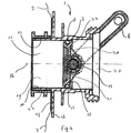
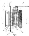
Figs. 1-6 show different views of an embodiment of abutterfly valve 1 according to the invention. InFigs. 1-3 thevalve 1 is shown in a closed condition and inFigs. 4-6 thevalve 1 is shown in an open condition. - Such a
butterfly valve 1 is used, for example, in the field of containers for storage of sterilized liquids. Thebutterfly valve 1 is suitable to be fixed to a foldable bag orcontainer 2 which is mounted in abox 3 such as shown inFig. 8 . Such a bag-in-box 4 including afoldable bag 2 is disclosed in the International Patent ApplicationWO 2004/022440 , see for exampleFigs. 1-5 in this application. - In
Figs. 8a-c the bag-in-box 4 principle is illustrated.Fig. 8a shows the initial state of thebag 2 when it is still empty. Thebag 2 is fixed to thebox 3 at afirst valve 5 and a second valve 6. It is also possible that the bag-in-box 4 has only onevalve 5, 6, for example only thefirst valve 5 for filling and emptying thebag 2. During filling of thebag 2 thebag 2 unfolds, such as shown inFig. 8b . At the end of the filling process thebag 2 obtains the shape of thebox 3 such as shown inFig. 8c . - In practice the bag-in-box 4 is often used for storage of sterilized products, such as liquids for nutritional products. Before filling the
bag 2 with a sterilized product thebag 2 as well as thevalves 5, 6 must be disinfected. This can be done by irradiation of theempty bag 2 and thevalves 5, 6 fixed thereto with gamma rays. - Before opening one of the
valves 5, 6 in order to fill thebag 2, thevalve 5, 6 is connected to a supply system (not shown) which will transfer the product through one of thevalves 5, 6 into thebag 2. After connection, the upstream part of thevalve 5, 6 is disinfected by exposing it to a hot fluid, such as steam, during a predetermined period. The hot fluid is provided via a side branch on a connecting pipe between the supply system and thevalve 5, 6, for example. Thereafter, thebag 2 can be filled with the sterilized product. This means that thevalve 5, 6 needs to have a good resistance against both high temperature and irradiation. Besides, the higher the allowable temperature the shorter the time period of disinfection may be before filling thebag 2. Thevalves 5, 6 may comprise thebutterfly valve 1 according to the invention. Therefore, when thebutterfly valve 1 is mentioned hereinafter, one be referred to thevalves 5, 6, as well. -
Fig. 1 shows that the embodiment of thebutterfly valve 1 according to the invention comprises ahousing 7 which can be made of plastic by injection moulding. Thehousing 7 is preferably made of a polycarbonate since this material has a good resistance against irradiation and high temperature for disinfecting such avalve 1. For example, polycarbonate degrades at a radiation level of more than 1000 kGray, whereas POM (PolyOxyMethylene), for example, already degrades above 15 kGray. - The
butterfly valve 1 further comprises alever 8 for opening and closing thevalve 1. A first end portion 9 of thehousing 7 is provided with an external thread on which a closure cap (not shown) can be screwed in the case when thebutterfly valve 1 is not operated, for example, during transport of thebag 2 to which thebutterfly valve 1 can be fixed. Asecond end portion 10 of thehousing 7 protrudes into thebag 2. -
Fig. 2 shows the inner side of thebutterfly valve 1. Thebutterfly valve 1 comprises apassageway 11, of which the circumferential edge is defined by aninternal surface 12 of thehousing 7. In the embodiment ofFigs. 1 - 6 thepassageway 11 has a circular cross-sectional area. - The
butterfly valve 1 is provided with avalve plate member 13, which has a circular plate-like shape and which is fixed to avalve shaft 14. Thevalve shaft 14 is eccentrically positioned with respect to thevalve plate member 13. Thevalve plate member 13 is enclosed by sealing means, in this case in the form of an elastic O-ring 15.Fig. 2 shows that in this embodiment a plane through the O-ring 15 extends perpendicular to acentre line 16 of thepassageway 11. - The
valve shaft 14 has an axis of rotation which extends across thepassageway 11 through thecentre line 16 and is rotatably mounted to thehousing 7. The central position of thevalve shaft 14 with respect to thecentre line 16 has the advantage that an internal or external pressure on thevalve plate member 13 at one of both sides thereof results in an even force distribution on thevalve plate member 13 with respect to the axis of rotation. Therefore, the external pressure will not generate an opening moment on thevalve plate member 13. An end portion of thevalve shaft 14 is fixed to thelever 8 so as to be able to rotate thevalve plate member 13 through thevalve shaft 14. Thevalve shaft 14 is supported bybearings 17 in thehousing 7 at opposite sides of thepassageway 11, seeFig. 3 . The space between thevalve shaft 14 and thehousing 7 can be provided with sealings to prevent leakage of hot fluid via this space during disinfection, such as described hereinbefore. - In a closed position of the
valve plate member 13 such as shown inFig. 2 the O-ring 15 enclosing thevalve plate member 13 is in engagement with a valve seat 18. In the embodiment shown inFig. 2 the valve seat 18 forms a part of theinternal surface 12 of thehousing 7. The valve seat 18 extends in a plane perpendicular to thecentre line 16 of thepassageway 11. The width of the valve seat may be determined by a contact surface between the O-ring 15 and theinternal surface 12 of thehousing 7. Thevalve shaft 14 has an axis of rotation spaced from the plane through the valve seat 18. - The
passageway 11 of thebutterfly valve 1 has aninlet 19 to be positioned within the container and anoutlet 20. Theinlet 19 is defined at the left side of thevalve plate member 13 and theoutlet 20 at the right side of thevalve plate member 13 inFig. 2 . - Such as shown in
Fig. 2 thevalve shaft 14 is located eccentrically with respect to thevalve plate member 13. This has the advantage that the O-ring 15 is not interrupted by a portion of thevalve shaft 14, such as might be the case with a centrically positionedvalve shaft 14. As a consequence thebutterfly valve 1 offers a sealed closure of thepassageway 11 and in the closed position of thevalve plate member 13 there is no risk of leakage via sealings of thevalve shaft 14 in thehousing 7 which is a typical phenomenon of centrically positionedvalve shafts 14. Furthermore, when theoutlet 20 side of thepassageway 11 is disinfected by a hot fluid, the fluid cannot reach theinlet 19 through sealings between thevalve shaft 14 and thehousing 7. - As a consequence of the eccentrically positioned
valve shaft 14 its axis is spaced from the plane through the valve seat 18. Therefore, the centre of the O-ring 15 moves away from thecentre line 16 of thepassageway 11 when opening thebutterfly valve 1. This means that in the open position the plane through the O-ring 15 intersects theinternal surface 12 of thehousing 7 to form a sectional area of thepassageway 11 having a width close to and parallel to the axis of rotation of thevalve shaft 14 which width is smaller than the initial outer diameter of the O-ring 15 in the closed position of thevalve plate member 13. This can be seen inFig. 6 : it may be clear that if thecircular passageway 11 had a uniform diameter over its length, the width of thepassageway 11 in a plane through the O-ring 15 in the open position of thevalve 1 would be smaller than the diameter of thepassageway 11. As a consequence, the flexible O-ring 15 would be compressed in the area where it crosses thevalve shaft 14. After filling thebag 2 and closing thebutterfly valve 1 the compressed portion of the O-ring 15 will expand in order to form a sealing between thevalve plate member 13 and theinner surface 12 of thehousing 7. However, the expansion takes some time, especially in cold conditions, and may result in some leakage just after filling. - This is solved according to the invention, such as can be seen in the embodiment of
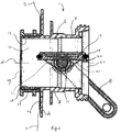
Fig. 2 , in which the cross-sectional area of thepassageway 11 at the right side of the valve seat 18 is larger than the cross-sectional area at the valve seat 18. Due to the eccentrically positionedvalve shaft 14 thevalve plate member 13 is not only rotated into a narrower part of thepassageway 11 when opened (such as described above), but it is also moved away from the plane through the valve seat 18 in the direction of the axis of rotation of thevalve shaft 14. Thus, in the open position the biggest circumferential part of the O-ring 15 is located beyond the valve seat 18 as viewed from the valve seat 18 in the direction of thevalve shaft 14, such as shown inFig. 5 . As the cross-sectional area of thepassageway 11 in the embodiment ofFig. 5 at the side of the valve seat 18 facing theoutlet 20 is larger than at the valve seat 18, the biggest part of the O-ring 15, and in particular the area where it crosses thevalve shaft 14, has more room in the opened position than in the case of a uniform diameter in axial direction of thepassageway 11. As a consequence, the O-ring is deformed less in the open position of thevalve plate member 13 such that in its closed position the risk of leakage is minimized. - It can be seen in
Fig. 2 that in this embodiment the diameter of thepassageway 11 increases gradually beyond the valve seat 18 as viewed from the valve seat 18 in the direction of thevalve shaft 14. This avoids a high local pressure on the O-ring compared to the case of a sudden diameter transition. -
Fig. 2 also shows that thevalve plate member 13 has a decreasing diameter in the direction of theinlet 20. Due to this shape the circumferential edge of thevalve plate member 13 does not contact the housing in the open position of thevalve plate member 13. - The
valve plate member 13 of the embodiment of thebutterfly valve 1 shown inFigs. 1-6 is provided withreinforcement ribs 21 which are located at the side of thevalve plate member 13 facing theoutlet 20 of thepassageway 11. Thereinforcement ribs 21 are clearly shown inFig. 3 . Theribs 21 can be integrally moulded together with thevalve plate member 13 and serve to minimize bending of thevalve plate member 13 in the case of disinfecting theoutlet 20 of thepassageway 11 with a hot fluid under high pressure, which presses against thevalve plate member 13 at theinlet side 19, for example at a pressure of 4 bar. - The
valve plate member 13 of the embodiment of thebutterfly valve 1 shown inFigs. 1-6 is also provided with a stop mechanism in the form of aprojection 22. Theprojection 22 is mounted on thevalve plate member 13 and projects beyond the circular outer edge of thevalve plate member 13, such as can be seen inFigs. 2 and3 . In this embodiment theprojection 22 is shaped such that it is in engagement with theinternal surface 12 of thehousing 7 at the right side of the valve seat inFig. 2 . As the cross-sectional area at the right side of the valve seat 18 is larger than at the valve seat 18 theprojection 22 prevents thevalve plate member 13 from rotating further in anti-clockwise direction when closing thebutterfly valve 1 than the closed position such as shown inFig. 2 . - The
valve plate member 13 can be made of polyamide and thevalve shaft 14 of fibre-reinforced polyamide. This material has a high-temperature and irradiation resistance. It is also possible to make thevalve shaft 14 and thevalve plate member 13 of polycarbonate. The advantage of using polycarbonate is that it is less hydroscopic than polyamide which means that it swells less when it is used in an aqueous environment. -
Fig. 2 shows the way in which thebag 2 is fixed to thebutterfly valve 1. Asleeve 23, which is preferably made of polyethylene is fixed to thebag 2, which is also preferably made of polyethylene, by heat-welding, for example. Thehousing 7 of thebutterfly valve 1 is fixed to thesleeve 23 by pressing thehousing 7 into thesleeve 23, such that the inner cylindrical wall of thesleeve 23 is fixed to the outer cylindrical wall of thehousing 7. - It is preferred that the
sleeve 23 protrudes into thebag 2, such as shown inFig. 8 . When thebag 2 is emptied and it folds to its original folded state, for example, amovable wall part 24 of thebag 2 may glide downwards along anopposite wall 25 of thebag 2 which is fixed to thebox 3. As thesleeve 23 protrudes in thebag 2 the downwardly slidingwall part 24 will not stick to the bag wall part surrounding thevalve 1 and thereby close-off theinlet 19 of thevalve 1, such that further emptying of thebag 2 would be impossible. A similar close-off effect is avoided in the case when theopposite wall 25 is not fixed to the box. An upper portion of thewall 25 may stick to and glide downwardly along a lower portion of thewall 25 during emptying the bag. Because of the protruding sleeve 32 the glidingwall 25 will not stick to the wall portion surrounding thevalve 1. - In
Fig. 1 it can be seen that thehousing 7 of thebutterfly valve 1 is provided with aflange 26. Theflange 26 faces an outer side of thebag 2, but it is not fixed to aflange 27 which may be part of thesleeve 23 and which faces theflange 26 of thehousing 7 when thehousing 7 and thesleeve 23 are in mounted condition. - Preferably, the
flange 27 of thesleeve 23 has a smaller diameter than theflange 26 of thehousing 7, seeFigs. 1-7 . If the diameter of theflange 27 of thesleeve 23 was larger than that of theflange 26 of thehousing 7, this would probably lead to cutting of thebag 2 near the edge of theflange 27 of the sleeve when thevalve 1 is positioned in the bag-in-box 4 combination such that theflange 27 of thesleeve 23 contacts a bottom of thebox 3. In that case, as thebag wall 25 inFig. 8 lies between the bottom of the box and theflange 27 of thesleeve 23, thebag wall 25 might be cut by theflange 27 of thesleeve 23 during vibrations of thebox 3, for example. Since the diameter of theflange 26 is larger than that of thesleeve 23 this problem does not occur. It should be noted that in the state-of-the-art theflange 27 of thesleeve 23 is secured to the bag wall by positioning theflange 27 against the bag wall from the inner side of the bag and heat-welding them together by using a heat-welding tool from the outer side of thebag 2, such that the bag wall is disposed between theflange 27 and the bottom of thebox 3 in the bag-in-box configuration ofFig. 8 . -
Fig. 7 shows an alternative embodiment of thebutterfly valve 1 according to the invention. In this embodiment the valve seat 18 has a decreasing cross-sectional area as viewed from theoutlet 20 to theinlet 19, i.e. a conical shape. Also in this embodiment the cross-sectional area of thepassageway 11 at theoutlet side 20 of the valve seat 18 is larger than the cross-sectional area at the valve seat 18, which means larger than the widest portion of the varying cross-sectional area of the valve seat 18 in this case. The advantage of this configuration of the valve seat 18 is that the space between the edge of thevalve plate member 13 and thehousing 7 at theinlet side 19 is decreased, which reduces the risk of blowing out the O-ring 18 from thevalve plate member 13 in the case when a fluid under high pressure is present at theoutlet side 20 during disinfecting of thevalve 1, for example. Furthermore, when a high pressure is present at theoutlet side 20, the valve plate member will be pressed against the conically-shaped valve seat 18. This means that the force exerted on thevalve shaft 14 is decreased such that it can be made of a light material. Besides, thereinforcement ribs 21 may be eliminated, as well. - Several dimensions of the shown embodiment of the
butterfly valve 1 according to the invention are generally interrelated and should preferably be chosen carefully. For example, the allowable inclination angle of the valve seat 18 inFig. 7 depends on the ratio of the radial distance from thecentre line 16 to the circumferential edge of thevalve plate member 13 and the axial distance from the axis of rotation to the plane through the O-ring 18. This inclination angle may generally not exceed the allowable value so as to avoid difficult opening of thevalve plate member 13. - From the foregoing it will be clear that the butterfly valve has such a configuration that leakage via the sealing means in the closed position is avoided, because of minimal deformation of the sealing means in the open position. The butterfly valve has a good resistance against high temperature and irradiation. The invention provides a container and valve assembly which comprises such a butterfly valve. Due to the features of the housing of the butterfly valve the container can be efficiently emptied.
- The invention is not restricted to the above-described embodiment as shown in the drawings. It may be apparent that various changes can be made in the embodiment without departing from the scope of the claims. For example, it is possible that the passageway has an oval or other shape instead of a circular one. Furthermore, a stopping mechanism may also be located between the lever and the housing so as to prevent the valve plate member from rotating further after arriving in the closed position when the valve is closed. The housing of the butterfly valve may also be fixed to the container in another way such as by gluing or heat-welding or alternative fixing methods.
Claims (15)
- A container (2) and valve (1, 5, 6) assembly, wherein the valve (1, 5, 6) and container (2) are mounted to each other such that the container (2) can be filled and/or emptied with liquid material by opening the valve (1, 5, 6), wherein the valve (1, 5, 6) comprises a butterfly valve (1), comprisinga housing (7) including a passageway (11) defined by an internal surface (12) of the housing (7), said passageway (11) having a centre line (16) in axial direction thereof,a valve seat (18) enclosing the passageway (11),a valve shaft (14) rotatably mounted to the housing (7) and having an axis of rotation extending through the centre line (16) and spaced from a plane through the valve seat (18),a valve plate member (13) fixed to the valve shaft (14) and being located in the passageway (11),sealing means (15) enclosing the valve plate member (13),said valve plate member (13) having an open position and a closed position, in which the sealing means (15) is in engagement with the valve seat (18) so as to close the passageway (11),characterized in that at least in a plane through the sealing means (15) in the open position, the width of the passageway (11) adjacent to the valve seat (18) as viewed from the valve seat (18) in the direction of the axis of rotation is larger than the width of the passageway (11) at the valve seat (18),wherein the housing (7) of the butterfly valve (1) comprises a flange (26) located on an external surface portion thereof, and the external surface portion is fixed to a sleeve (23) which is mounted to a hole of the container (2) whereas the flange (26) faces an external wall of the container (2),wherein the sleeve (23) includes a flange (27) opposite to the flange (26) of the housing (7), said flange (26) of the housing (7) having a circumferential edge which extends at least partly beyond a circumferential edge of the flange (27) of the sleeve (23) as viewed from the centre line (16).
- An assembly according to claim 1, wherein the cross-sectional area of the passageway (11) has a circumferential edge, which circumferential edge adjacent to the valve seat (18) as viewed from the valve seat (18) in the direction of the axis of rotation of the valve shaft (14) extends beyond the circumferential edge at the valve seat (18) in radial direction thereof.
- An assembly according to claim 1 or 2, wherein the cross-sectional area of the passageway (11) beyond the valve seat (18) as viewed from the valve seat (18) in the direction of the axis of rotation of the valve shaft (14) gradually increases.
- An assembly according to one of the preceding claims, wherein the passageway (11) has a circular cross-sectional area.
- An assembly according to one of the preceding claims, wherein the cross-sectional area of the passageway (11) at least at the valve seat (18) decreases in axial direction of the passageway (11).
- An assembly according to claim 5, wherein the cross-sectional area of the passageway (11) decreases up to an axial location of the passageway (11) adjacent to an end portion of the valve plate member (13) in its closed position, which end portion is located on the valve plate member (13) in a direction as viewed from the axis of rotation to the sealing means (15).
- An assembly according to one of the preceding claims, wherein the passageway (11) comprises an inlet (19) at one side and an outlet (20) at an opposite side of the valve plate member (13), and the valve plate member (13) is provided with reinforcement ribs (21) located at a side of the valve plate member (13) facing the outlet (20).
- An assembly according to claim 7, wherein the reinforcement ribs (21) are located next to the valve shaft (14) as viewed from the plane through the sealing means (15) in a direction perpendicular thereto.
- An assembly according to one of the preceding claims, wherein the butterfly valve (1) comprises a stop mechanism (22) for stopping the valve plate member (13) with respect to the housing (7) when it is rotated from its open position to its closed position.
- An assembly according to claim 9, wherein the stop mechanism (22) comprises a projection (22) mounted to the valve plate member (13) which projects beyond the circumference of the valve plate member (13) in a radial direction of the plane through the sealing means (15) substantially perpendicular to the axis of rotation.
- An assembly according to one of the preceding claims, wherein the housing (7) is made of polycarbonate.
- An assembly according to one of the preceding claims, wherein the valve plate member (13) is made of polyamide, and the valve shaft (14) is made of fibre-reinforced polyamide.
- An assembly according to one of the claims 1-11, wherein the valve plate member (13) and/or the valve shaft (14) are made of polycarbonate.
- A container (2) and valve (1, 5, 6) assembly according to one of the preceding claims, wherein the container (2) comprises a foldable bag (2) which is arranged such that it folds when it is emptied, and the bag (2) is secured to the housing (7) of the butterfly valve (1) at a location thereof spaced from an end of the housing (7) which protrudes in the bag (2) .
- A container (2) and valve (1, 5, 6) assembly according to one of the preceding claims, wherein the housing (7) of the butterfly valve (1) is fixed to the sleeve (23) by pressing the housing (7) into the sleeve (23).
Priority Applications (1)
| Application Number | Priority Date | Filing Date | Title |
|---|---|---|---|
| PL06733082T PL2021663T3 (en) | 2006-04-28 | 2006-04-28 | Butterfly valve |
Applications Claiming Priority (1)
| Application Number | Priority Date | Filing Date | Title |
|---|---|---|---|
| PCT/NL2006/050104 WO2007126305A1 (en) | 2006-04-28 | 2006-04-28 | Butterfly valve |
Publications (3)
| Publication Number | Publication Date |
|---|---|
| EP2021663A1 EP2021663A1 (en) | 2009-02-11 |
| EP2021663B1 true EP2021663B1 (en) | 2018-12-12 |
| EP2021663B8 EP2021663B8 (en) | 2019-03-06 |
Family
ID=37654737
Family Applications (1)
| Application Number | Title | Priority Date | Filing Date |
|---|---|---|---|
| EP06733082.9A Expired - Lifetime EP2021663B8 (en) | 2006-04-28 | 2006-04-28 | Butterfly valve |
Country Status (7)
| Country | Link |
|---|---|
| US (1) | US9377111B2 (en) |
| EP (1) | EP2021663B8 (en) |
| CN (1) | CN101466971A (en) |
| BR (1) | BRPI0621637A2 (en) |
| ES (1) | ES2712897T3 (en) |
| PL (1) | PL2021663T3 (en) |
| WO (1) | WO2007126305A1 (en) |
Families Citing this family (11)
| Publication number | Priority date | Publication date | Assignee | Title |
|---|---|---|---|---|
| EP2133608A1 (en) * | 2008-06-09 | 2009-12-16 | Chi Men Precision Co., Ltd. | Butterfly valve |
| FR2940393B1 (en) * | 2008-12-18 | 2016-07-29 | Valeo Systemes De Controle Moteur | SHUTTER COMPONENT FOR A GAS FLOW CONDUIT AND DUCT WITH THE SHUTTER |
| US9783347B2 (en) * | 2015-06-30 | 2017-10-10 | Scholle Ipn Corporation | Valve assembly |
| WO2017011673A2 (en) * | 2015-07-14 | 2017-01-19 | Hartman Thomas A | Spring ring valve seat and butterfly valve with spring ring valve seat |
| CN108679242B (en) * | 2018-06-21 | 2024-02-27 | 上海鸿研物流技术有限公司 | Articulated valve |
| USD872836S1 (en) | 2018-10-03 | 2020-01-14 | A.R. Arena Products, Inc. | Butterfly valve |
| CN113490808B (en) * | 2019-02-28 | 2025-06-03 | 株式会社开滋 | Double eccentric butterfly valve body and double eccentric butterfly valve |
| WO2020237007A1 (en) | 2019-05-23 | 2020-11-26 | Ecolab Usa Inc. | Dispensing system |
| CN116857409A (en) * | 2023-06-30 | 2023-10-10 | 上海箱箱智能科技有限公司 | Flange piece, valve, liquid bag and container |
| CN116697059B (en) * | 2023-07-05 | 2026-04-21 | 航大阀门集团有限公司 | Butterfly valve |
| CN120626758B (en) * | 2025-07-25 | 2026-02-03 | 瑟维斯泵阀制造(浙江)有限公司 | Ultralow temperature self-compensating flexible sealing butterfly valve |
Family Cites Families (26)
| Publication number | Priority date | Publication date | Assignee | Title |
|---|---|---|---|---|
| GB689630A (en) * | 1950-01-25 | 1953-04-01 | Power Jets Res & Dev Ltd | Improvements in or relating to butterfly valves |
| GB873117A (en) * | 1957-12-03 | 1961-07-19 | White & Co Ltd Samuel | Improvements in butterfly valves |
| GB960915A (en) * | 1961-10-31 | 1964-06-17 | Mechans Ltd | Improvements in or relating to butterfly valves |
| US3521857A (en) * | 1966-07-04 | 1970-07-28 | Kinematics Ltd | Butterfly valves |
| BR7505730A (en) * | 1974-09-12 | 1976-08-03 | Panamera Ag | VALVE DISC TO A BUTTERFLY VALVE; BUTTERFLY VALVE PROCESS TO CENTER A SEAL RING FROM A BUTTERFLY VALVE AND PROCESS TO SEAL A BUTTERFLY VALVE |
| FR2494383A1 (en) * | 1980-11-19 | 1982-05-21 | Gachot Jean | BUTTERFLY VALVE |
| DE8301963U1 (en) * | 1983-01-26 | 1983-07-14 | Deka Armaturen Gmbh, 4403 Senden, De | LOCKING VALVE FOR LARGE VOLUME STEAM PIPES |
| GB8320783D0 (en) * | 1983-08-02 | 1983-09-01 | Matburn Holdings Ltd | Taps |
| US5626254A (en) * | 1994-08-26 | 1997-05-06 | Podd; Stephen D. | Apparatus and method for rapid installation of container liner and access ports |
| US5579953A (en) * | 1994-08-30 | 1996-12-03 | Plastic Systems Inc. | Liquid container and valve |
| SE9601092L (en) * | 1996-03-21 | 1997-04-07 | Alfapac Ab | Liner for fluid container |
| SE512520C2 (en) * | 1997-07-07 | 2000-03-27 | Arca Systems Ab | Bag-shaped inner casing in the form of a so-called liner intended for use in the transport and storage of bulk goods together with a supporting outer casing |
| US6131767A (en) * | 1998-09-09 | 2000-10-17 | Scholle Corporation | Tap for dispensing fluid |
| IT246930Y1 (en) * | 1999-12-09 | 2002-04-10 | Bonomi Bresciane Rubinetterie | INTERCEPTION VALVE FOR FLUIDS WITH BUTTERFLY SHUTTER ORDER WITH HIGH RELIABILITY OF OPERATION |
| DE19959367C2 (en) * | 1999-12-09 | 2003-03-06 | Protechna Sa | Butterfly valve for liquid containers or liquid lines |
| US6494466B1 (en) * | 2000-04-20 | 2002-12-17 | Thomas A. Hartman | Valve seal construction with non-congruent side serrations |
| US6880808B2 (en) | 2002-05-03 | 2005-04-19 | Acist Medical Systems, Inc. | Gamma-stable high pressure stopcock |
| NL1021401C2 (en) * | 2002-09-05 | 2004-03-08 | Smq Group B V | Foldable bag. |
| RU2229432C1 (en) | 2003-01-16 | 2004-05-27 | Ефимкин Максим Леонидович | Cock |
| JP4412963B2 (en) | 2003-10-10 | 2010-02-10 | 旭有機材工業株式会社 | Plastic parts for valves |
| DE102004056764B4 (en) * | 2003-11-25 | 2009-10-08 | Aisan Kogyo Kabushiki Kaisha, Obu | Throttle body and method for producing such throttle body |
| FR2864036B1 (en) | 2003-12-23 | 2006-02-10 | Rehau Sa | TAP FOR CONTAINER, A MOLDED ONE PIECE MOLDED INVIOLABILITY WALL WITH TAP BODY |
| CA2554832C (en) * | 2004-02-03 | 2012-05-08 | Liqui-Box Canada Inc. | Threaded spout |
| US7721759B2 (en) * | 2005-09-07 | 2010-05-25 | Chep Technology Pty Limited | Valve having a protective cage |
| RU52151U1 (en) | 2005-09-22 | 2006-03-10 | Ольга Витальевна Исаева | BUSHING CONNECTING |
| EP1842791A1 (en) * | 2006-04-06 | 2007-10-10 | Amka | Tap and liquid dispenser for a bag-in-box |
-
2006
- 2006-04-28 CN CNA2006800549953A patent/CN101466971A/en active Pending
- 2006-04-28 ES ES06733082T patent/ES2712897T3/en not_active Expired - Lifetime
- 2006-04-28 PL PL06733082T patent/PL2021663T3/en unknown
- 2006-04-28 WO PCT/NL2006/050104 patent/WO2007126305A1/en not_active Ceased
- 2006-04-28 US US12/298,842 patent/US9377111B2/en active Active
- 2006-04-28 EP EP06733082.9A patent/EP2021663B8/en not_active Expired - Lifetime
- 2006-04-28 BR BRPI0621637-4A patent/BRPI0621637A2/en not_active Application Discontinuation
Non-Patent Citations (1)
| Title |
|---|
| None * |
Also Published As
| Publication number | Publication date |
|---|---|
| EP2021663A1 (en) | 2009-02-11 |
| WO2007126305A1 (en) | 2007-11-08 |
| BRPI0621637A2 (en) | 2011-12-13 |
| US20100044373A1 (en) | 2010-02-25 |
| EP2021663B8 (en) | 2019-03-06 |
| CN101466971A (en) | 2009-06-24 |
| US9377111B2 (en) | 2016-06-28 |
| ES2712897T3 (en) | 2019-05-16 |
| PL2021663T3 (en) | 2019-04-30 |
Similar Documents
| Publication | Publication Date | Title |
|---|---|---|
| EP2021663B1 (en) | Butterfly valve | |
| US4141474A (en) | Self-closing closure utilizing a single diaphragm | |
| US4700744A (en) | Double shut-off fluid dispenser element | |
| US6637725B2 (en) | Universal quick-disconnect coupling and valve | |
| US6354466B1 (en) | Valve assembly for liner bags of containers having a liner puncture/piercing means | |
| EP0700353A1 (en) | AUTOMATIC CLOSING DEVICE | |
| JP4262833B2 (en) | Valve device for bag with protective case | |
| JPH0550630B2 (en) | ||
| JP2002540026A (en) | A device for filling a container with an integrated cleaning device | |
| AU2002253428B2 (en) | Taps for controlling liquid flow | |
| CN113165859A (en) | Kit for dispensing a beverage through a dispensing tube comprising a dispensing valve | |
| AU2002253428A1 (en) | Taps for controlling liquid flow | |
| EP3317566B1 (en) | Valve assembly | |
| JP2003208229A (en) | Flow rate control valve | |
| EP0115164A1 (en) | Improvements in or relating to valves | |
| EP1607664B1 (en) | Valve actuating apparatus | |
| NO811373L (en) | FLUIDUMSTROEMSTYREVENTIL. | |
| IE45521B1 (en) | A self-closing closure utilizing a single diaphragm | |
| JP7721482B2 (en) | Gasket for beverage servers | |
| EP0465545A1 (en) | Valve assembly with axially movable valve | |
| AU2005232320B2 (en) | A spout for a container | |
| AU753361B2 (en) | A valve assembly for liner bags for containers | |
| AU632177B2 (en) | Dispensing valve | |
| MXPA06004500A (en) | Adjustable sealing means | |
| ZA200308335B (en) | Taps for controlling liquid flow. |
Legal Events
| Date | Code | Title | Description |
|---|---|---|---|
| PUAI | Public reference made under article 153(3) epc to a published international application that has entered the european phase |
Free format text: ORIGINAL CODE: 0009012 |
|
| 17P | Request for examination filed |
Effective date: 20081128 |
|
| AK | Designated contracting states |
Kind code of ref document: A1 Designated state(s): AT BE BG CH CY CZ DE DK EE ES FI FR GB GR HU IE IS IT LI LT LU LV MC NL PL PT RO SE SI SK TR |
|
| AX | Request for extension of the european patent |
Extension state: AL BA HR MK YU |
|
| 17Q | First examination report despatched |
Effective date: 20090331 |
|
| DAX | Request for extension of the european patent (deleted) | ||
| RAP1 | Party data changed (applicant data changed or rights of an application transferred) |
Owner name: SCHOLLE CORPORATION |
|
| STAA | Information on the status of an ep patent application or granted ep patent |
Free format text: STATUS: EXAMINATION IS IN PROGRESS |
|
| GRAP | Despatch of communication of intention to grant a patent |
Free format text: ORIGINAL CODE: EPIDOSNIGR1 |
|
| STAA | Information on the status of an ep patent application or granted ep patent |
Free format text: STATUS: GRANT OF PATENT IS INTENDED |
|
| INTG | Intention to grant announced |
Effective date: 20180808 |
|
| GRAS | Grant fee paid |
Free format text: ORIGINAL CODE: EPIDOSNIGR3 |
|
| GRAA | (expected) grant |
Free format text: ORIGINAL CODE: 0009210 |
|
| STAA | Information on the status of an ep patent application or granted ep patent |
Free format text: STATUS: THE PATENT HAS BEEN GRANTED |
|
| AK | Designated contracting states |
Kind code of ref document: B1 Designated state(s): AT BE BG CH CY CZ DE DK EE ES FI FR GB GR HU IE IS IT LI LT LU LV MC NL PL PT RO SE SI SK TR |
|
| REG | Reference to a national code |
Ref country code: GB Ref legal event code: FG4D |
|
| REG | Reference to a national code |
Ref country code: CH Ref legal event code: EP |
|
| REG | Reference to a national code |
Ref country code: AT Ref legal event code: REF Ref document number: 1076468 Country of ref document: AT Kind code of ref document: T Effective date: 20181215 |
|
| REG | Reference to a national code |
Ref country code: DE Ref legal event code: R096 Ref document number: 602006057046 Country of ref document: DE |
|
| REG | Reference to a national code |
Ref country code: IE Ref legal event code: FG4D |
|
| RAP2 | Party data changed (patent owner data changed or rights of a patent transferred) |
Owner name: SCHOLLE IPN CORPORATION |
|
| REG | Reference to a national code |
Ref country code: NL Ref legal event code: FP |
|
| REG | Reference to a national code |
Ref country code: CH Ref legal event code: PK Free format text: BERICHTIGUNG B8 |
|
| REG | Reference to a national code |
Ref country code: DE Ref legal event code: R082 Ref document number: 602006057046 Country of ref document: DE Representative=s name: RGTH RICHTER GERBAULET THIELEMANN HOFMANN PATE, DE |
|
| REG | Reference to a national code |
Ref country code: LT Ref legal event code: MG4D |
|
| PG25 | Lapsed in a contracting state [announced via postgrant information from national office to epo] |
Ref country code: LV Free format text: LAPSE BECAUSE OF FAILURE TO SUBMIT A TRANSLATION OF THE DESCRIPTION OR TO PAY THE FEE WITHIN THE PRESCRIBED TIME-LIMIT Effective date: 20181212 Ref country code: BG Free format text: LAPSE BECAUSE OF FAILURE TO SUBMIT A TRANSLATION OF THE DESCRIPTION OR TO PAY THE FEE WITHIN THE PRESCRIBED TIME-LIMIT Effective date: 20190312 Ref country code: LT Free format text: LAPSE BECAUSE OF FAILURE TO SUBMIT A TRANSLATION OF THE DESCRIPTION OR TO PAY THE FEE WITHIN THE PRESCRIBED TIME-LIMIT Effective date: 20181212 Ref country code: FI Free format text: LAPSE BECAUSE OF FAILURE TO SUBMIT A TRANSLATION OF THE DESCRIPTION OR TO PAY THE FEE WITHIN THE PRESCRIBED TIME-LIMIT Effective date: 20181212 |
|
| REG | Reference to a national code |
Ref country code: AT Ref legal event code: MK05 Ref document number: 1076468 Country of ref document: AT Kind code of ref document: T Effective date: 20181212 |
|
| REG | Reference to a national code |
Ref country code: ES Ref legal event code: FG2A Ref document number: 2712897 Country of ref document: ES Kind code of ref document: T3 Effective date: 20190516 |
|
| PG25 | Lapsed in a contracting state [announced via postgrant information from national office to epo] |
Ref country code: GR Free format text: LAPSE BECAUSE OF FAILURE TO SUBMIT A TRANSLATION OF THE DESCRIPTION OR TO PAY THE FEE WITHIN THE PRESCRIBED TIME-LIMIT Effective date: 20190313 Ref country code: SE Free format text: LAPSE BECAUSE OF FAILURE TO SUBMIT A TRANSLATION OF THE DESCRIPTION OR TO PAY THE FEE WITHIN THE PRESCRIBED TIME-LIMIT Effective date: 20181212 |
|
| PG25 | Lapsed in a contracting state [announced via postgrant information from national office to epo] |
Ref country code: CZ Free format text: LAPSE BECAUSE OF FAILURE TO SUBMIT A TRANSLATION OF THE DESCRIPTION OR TO PAY THE FEE WITHIN THE PRESCRIBED TIME-LIMIT Effective date: 20181212 Ref country code: PT Free format text: LAPSE BECAUSE OF FAILURE TO SUBMIT A TRANSLATION OF THE DESCRIPTION OR TO PAY THE FEE WITHIN THE PRESCRIBED TIME-LIMIT Effective date: 20190412 |
|
| PG25 | Lapsed in a contracting state [announced via postgrant information from national office to epo] |
Ref country code: RO Free format text: LAPSE BECAUSE OF FAILURE TO SUBMIT A TRANSLATION OF THE DESCRIPTION OR TO PAY THE FEE WITHIN THE PRESCRIBED TIME-LIMIT Effective date: 20181212 Ref country code: SK Free format text: LAPSE BECAUSE OF FAILURE TO SUBMIT A TRANSLATION OF THE DESCRIPTION OR TO PAY THE FEE WITHIN THE PRESCRIBED TIME-LIMIT Effective date: 20181212 Ref country code: IS Free format text: LAPSE BECAUSE OF FAILURE TO SUBMIT A TRANSLATION OF THE DESCRIPTION OR TO PAY THE FEE WITHIN THE PRESCRIBED TIME-LIMIT Effective date: 20190412 Ref country code: EE Free format text: LAPSE BECAUSE OF FAILURE TO SUBMIT A TRANSLATION OF THE DESCRIPTION OR TO PAY THE FEE WITHIN THE PRESCRIBED TIME-LIMIT Effective date: 20181212 |
|
| REG | Reference to a national code |
Ref country code: DE Ref legal event code: R097 Ref document number: 602006057046 Country of ref document: DE |
|
| PLBE | No opposition filed within time limit |
Free format text: ORIGINAL CODE: 0009261 |
|
| STAA | Information on the status of an ep patent application or granted ep patent |
Free format text: STATUS: NO OPPOSITION FILED WITHIN TIME LIMIT |
|
| PG25 | Lapsed in a contracting state [announced via postgrant information from national office to epo] |
Ref country code: SI Free format text: LAPSE BECAUSE OF FAILURE TO SUBMIT A TRANSLATION OF THE DESCRIPTION OR TO PAY THE FEE WITHIN THE PRESCRIBED TIME-LIMIT Effective date: 20181212 Ref country code: DK Free format text: LAPSE BECAUSE OF FAILURE TO SUBMIT A TRANSLATION OF THE DESCRIPTION OR TO PAY THE FEE WITHIN THE PRESCRIBED TIME-LIMIT Effective date: 20181212 Ref country code: AT Free format text: LAPSE BECAUSE OF FAILURE TO SUBMIT A TRANSLATION OF THE DESCRIPTION OR TO PAY THE FEE WITHIN THE PRESCRIBED TIME-LIMIT Effective date: 20181212 |
|
| 26N | No opposition filed |
Effective date: 20190913 |
|
| REG | Reference to a national code |
Ref country code: CH Ref legal event code: PL |
|
| REG | Reference to a national code |
Ref country code: BE Ref legal event code: MM Effective date: 20190430 |
|
| PG25 | Lapsed in a contracting state [announced via postgrant information from national office to epo] |
Ref country code: LU Free format text: LAPSE BECAUSE OF NON-PAYMENT OF DUE FEES Effective date: 20190428 Ref country code: MC Free format text: LAPSE BECAUSE OF FAILURE TO SUBMIT A TRANSLATION OF THE DESCRIPTION OR TO PAY THE FEE WITHIN THE PRESCRIBED TIME-LIMIT Effective date: 20181212 |
|
| PG25 | Lapsed in a contracting state [announced via postgrant information from national office to epo] |
Ref country code: CH Free format text: LAPSE BECAUSE OF NON-PAYMENT OF DUE FEES Effective date: 20190430 Ref country code: LI Free format text: LAPSE BECAUSE OF NON-PAYMENT OF DUE FEES Effective date: 20190430 |
|
| PG25 | Lapsed in a contracting state [announced via postgrant information from national office to epo] |
Ref country code: FR Free format text: LAPSE BECAUSE OF NON-PAYMENT OF DUE FEES Effective date: 20190430 Ref country code: BE Free format text: LAPSE BECAUSE OF NON-PAYMENT OF DUE FEES Effective date: 20190430 |
|
| PG25 | Lapsed in a contracting state [announced via postgrant information from national office to epo] |
Ref country code: TR Free format text: LAPSE BECAUSE OF FAILURE TO SUBMIT A TRANSLATION OF THE DESCRIPTION OR TO PAY THE FEE WITHIN THE PRESCRIBED TIME-LIMIT Effective date: 20181212 |
|
| PG25 | Lapsed in a contracting state [announced via postgrant information from national office to epo] |
Ref country code: IE Free format text: LAPSE BECAUSE OF NON-PAYMENT OF DUE FEES Effective date: 20190428 |
|
| PG25 | Lapsed in a contracting state [announced via postgrant information from national office to epo] |
Ref country code: CY Free format text: LAPSE BECAUSE OF FAILURE TO SUBMIT A TRANSLATION OF THE DESCRIPTION OR TO PAY THE FEE WITHIN THE PRESCRIBED TIME-LIMIT Effective date: 20181212 |
|
| PG25 | Lapsed in a contracting state [announced via postgrant information from national office to epo] |
Ref country code: HU Free format text: LAPSE BECAUSE OF FAILURE TO SUBMIT A TRANSLATION OF THE DESCRIPTION OR TO PAY THE FEE WITHIN THE PRESCRIBED TIME-LIMIT; INVALID AB INITIO Effective date: 20060428 |
|
| PGFP | Annual fee paid to national office [announced via postgrant information from national office to epo] |
Ref country code: NL Payment date: 20250422 Year of fee payment: 20 |
|
| PGFP | Annual fee paid to national office [announced via postgrant information from national office to epo] |
Ref country code: PL Payment date: 20250418 Year of fee payment: 20 Ref country code: DE Payment date: 20250417 Year of fee payment: 20 |
|
| PGFP | Annual fee paid to national office [announced via postgrant information from national office to epo] |
Ref country code: GB Payment date: 20250423 Year of fee payment: 20 Ref country code: ES Payment date: 20250519 Year of fee payment: 20 |
|
| PGFP | Annual fee paid to national office [announced via postgrant information from national office to epo] |
Ref country code: IT Payment date: 20250430 Year of fee payment: 20 |