JP4262833B2 - Valve device for bag with protective case - Google Patents
Valve device for bag with protective case Download PDFInfo
- Publication number
- JP4262833B2 JP4262833B2 JP15775999A JP15775999A JP4262833B2 JP 4262833 B2 JP4262833 B2 JP 4262833B2 JP 15775999 A JP15775999 A JP 15775999A JP 15775999 A JP15775999 A JP 15775999A JP 4262833 B2 JP4262833 B2 JP 4262833B2
- Authority
- JP
- Japan
- Prior art keywords
- valve plate
- shaft
- bag
- convex
- cam
- Prior art date
- Legal status (The legal status is an assumption and is not a legal conclusion. Google has not performed a legal analysis and makes no representation as to the accuracy of the status listed.)
- Expired - Lifetime
Links
Images


Classifications
-
- B—PERFORMING OPERATIONS; TRANSPORTING
- B67—OPENING, CLOSING OR CLEANING BOTTLES, JARS OR SIMILAR CONTAINERS; LIQUID HANDLING
- B67D—DISPENSING, DELIVERING OR TRANSFERRING LIQUIDS, NOT OTHERWISE PROVIDED FOR
- B67D3/00—Apparatus or devices for controlling flow of liquids under gravity from storage containers for dispensing purposes
- B67D3/04—Liquid-dispensing taps or cocks adapted to seal and open tapping holes of casks, e.g. for beer
- B67D3/043—Liquid-dispensing taps or cocks adapted to seal and open tapping holes of casks, e.g. for beer with a closing element having a linear movement, in a direction perpendicular to the seat
-
- B—PERFORMING OPERATIONS; TRANSPORTING
- B67—OPENING, CLOSING OR CLEANING BOTTLES, JARS OR SIMILAR CONTAINERS; LIQUID HANDLING
- B67D—DISPENSING, DELIVERING OR TRANSFERRING LIQUIDS, NOT OTHERWISE PROVIDED FOR
- B67D3/00—Apparatus or devices for controlling flow of liquids under gravity from storage containers for dispensing purposes
- B67D3/04—Liquid-dispensing taps or cocks adapted to seal and open tapping holes of casks, e.g. for beer
- B67D3/045—Liquid-dispensing taps or cocks adapted to seal and open tapping holes of casks, e.g. for beer with a closing element having a linear movement, in a direction parallel to the seat
-
- B—PERFORMING OPERATIONS; TRANSPORTING
- B67—OPENING, CLOSING OR CLEANING BOTTLES, JARS OR SIMILAR CONTAINERS; LIQUID HANDLING
- B67D—DISPENSING, DELIVERING OR TRANSFERRING LIQUIDS, NOT OTHERWISE PROVIDED FOR
- B67D3/00—Apparatus or devices for controlling flow of liquids under gravity from storage containers for dispensing purposes
- B67D3/04—Liquid-dispensing taps or cocks adapted to seal and open tapping holes of casks, e.g. for beer
- B67D3/047—Liquid-dispensing taps or cocks adapted to seal and open tapping holes of casks, e.g. for beer with a closing element having a rotational movement
-
- F—MECHANICAL ENGINEERING; LIGHTING; HEATING; WEAPONS; BLASTING
- F16—ENGINEERING ELEMENTS AND UNITS; GENERAL MEASURES FOR PRODUCING AND MAINTAINING EFFECTIVE FUNCTIONING OF MACHINES OR INSTALLATIONS; THERMAL INSULATION IN GENERAL
- F16K—VALVES; TAPS; COCKS; ACTUATING-FLOATS; DEVICES FOR VENTING OR AERATING
- F16K3/00—Gate valves or sliding valves, i.e. cut-off apparatus with closing members having a sliding movement along the seat for opening and closing
- F16K3/02—Gate valves or sliding valves, i.e. cut-off apparatus with closing members having a sliding movement along the seat for opening and closing with flat sealing faces; Packings therefor
- F16K3/04—Gate valves or sliding valves, i.e. cut-off apparatus with closing members having a sliding movement along the seat for opening and closing with flat sealing faces; Packings therefor with pivoted closure members
- F16K3/10—Gate valves or sliding valves, i.e. cut-off apparatus with closing members having a sliding movement along the seat for opening and closing with flat sealing faces; Packings therefor with pivoted closure members with special arrangements for separating the sealing faces or for pressing them together
Abstract
Description
【0001】
【発明の属する技術分野】
この発明は、保護ケース(box)の中に袋(bag)が入れられた保護ケース入り袋(bag and box combination)に関する。より具体的には、改良された弁機構を具える保護ケース入り袋に関する。この保護ケース入り袋はバッグインボックスと称されることもある。
【0002】
【従来の技術及び発明が解決しようとする課題】
保護ケース入り袋は、一般的には、幾つかの形態の取出機構(fitment)が袋に取り付けられており、該取出機構は、剛性の外側ケースの側壁に形成された開口を貫通している。配送の際、取出機構の通路は密閉される。通路の密閉は、例えば、メンブレンにより、又は取出機構の取り付け用フランジの内側、即ち外側ケースから離れた方の取り付け用フランジに溶接されることにより行われる。それゆえ、袋は、実際には、取出機構の中を通る通路を覆っている。多くの場合、取出機構用メンブレンと、取出機構の露出端部にキャップ又はプラグ等を取り付けることにより、配送中、取出口が密閉されるようにしている。
【0003】
輸送又は配送の際、保護ケース入り袋は、これらの密閉手段によって密閉されるが、袋から材料(例えば、液体)を取り出すために、取出機構の中を通る通路を開ける必要が生ずる。この開口操作は、一般的に外部の弁を用いて行われる。この外部弁は、キャップ又はプラグの代わりに取出機構へ固定されており、取出機構の通路を密閉する袋又はメンブレンに穴をあける手段が設けられている。
【0004】
これら機構の取扱いは非常に困難であり、袋の内容物が取り出されるべき位置に制御弁を取り付ける必要がある。この弁は袋が空になるまで取り付けられたままであるから、保護ケース入り袋を移動させるのが更に困難となる。また、弁を適当な位置に取り付けて、袋と弁をユニットとして輸送又は配送を行なうこともできるが、必要以上に大きなパレットが必要となるので、コストの上昇を招き、輸送中の漏洩のおそれも増す。
【0005】
剛性ケースに使用するゲート弁は随分前から知られている。例えば、1869年3月23日にチェイズ氏等に付与された米国特許第88008号、1894年6月26日に発行された米国特許第521832号、1899年10月10日にハウ氏等に付与された米国特許第634730号、もっと最近では、1967年5月23日にアップに付与された米国特許第3321175号を参照することができる。
【0006】
チェイズ氏等の特許に記載されたプレート又はゲート弁は、剛性シャフト軸の上に枢支されており、回転によって開位置と閉位置の間を移動することにより、プレートの位置が調節される。これは、上記の全ての特許に共通している。更に、上記の特許は全て、この弁を剛性体(可撓性袋に対向する)へ取り付けるようにしているから、弁板は、接続された構造体に干渉することなく、開位置から閉位置へ容易に移動することができる。
【0007】
チェイズ氏等の特許が提供する装置は、弁板が剛性ブロックの内部に収容され、弁板の移動は、前記ブロックにより、ブロック構造体の幅に限定される。この場合、ブロック構造体は、弁板が移動する間、開位置及び閉位置の両方の位置で弁板を収容するのに十分な大きさでなくてはならない。そのため、前記装置は比較的嵩が高く、多くの目的に対して有効でないことが多い。
【0008】
【課題を解決するための手段及び発明の効果】
本発明の目的は、保護ケースに入れられた袋への使用に特に適した新規な弁構造を提供することである。
本発明の目的は、弁が組み込まれた取出機構を有する保護ケース入り袋を提供することである。
【0009】
広い意味において、本発明は、弁を具えた取出機構に関するもので、軸方向に通路が形成された本体部と、本体部に形成されて通路の内側端部を取り囲む環状の径方向フランジと、弁板と、該弁板を本体部に回動可能に取り付けるシャフトと、弁板をシャフトの長軸と同じ方向(parallel)に移動させるためのデュアルアクティングカム(dual acting cam)とを具え、弁板はシャフトと共にシャフトの周りを回転できるようになし、シャフトの長軸は、軸方向通路の長軸とその内端部で平行で、軸方向通路の一方の側と間隔を有しており、弁板は、シャフトの回転により閉位置になると、軸方向通路を密閉し、シャフトの回転により開位置になると、軸方向通路を開けるようになっており、デュアルアクティングカムは、弁板に接続された第1のカム手段と、本体部に取り付けられた協働カム手段(cooperating cam means)を含んでおり、第1のカム手段と協働カム手段は、弁手段がシャフトによって閉位置へ回転されたとき、弁板を表面の方へ移動させ、弁板が開位置へ回転されたとき、弁板を表面から離れる方向へ移動させるように作用する。
【0010】
広い意味において、本発明は保護ケース入り袋に関するもので、これは、外側が、堅い壁を有する容器、内側が、該容器の中に収容される可撓性袋体であり、可撓性袋体は、内部が満たされると、容器の堅い壁によって支持されるようになっており、袋体には取出機構が取り付けられ、容器には堅い壁を貫通する孔が形成され、該孔は取出機構の突出部が通る通路を構成しており、前記取出機構は、軸方向に通路が形成された本体部と、本体部に形成されて通路の内側端部を取り囲む環状の径方向フランジと、弁板と、該弁板を本体部に回動可能に取り付けるシャフトを具えており、弁板はシャフトと共にシャフトの周りを回転できるようになし、シャフトの長軸は、軸方向通路の長軸とその内端部で平行で、軸方向通路の一方の側と間隔を有しており、弁板は、シャフトの回転により閉位置になると、軸方向通路を密閉し、シャフトの回転により開位置になると、軸方向通路を開く。
【0011】
望ましい取出機構は、弁板をシャフトの長軸と同じ方向に移動させるためのデュアルアクティングカムを具えており、デュアルアクティングカムは、弁板に接続された第1のカム手段と、本体部に取り付けられた協働カム手段を含んでおり、第1のカム手段と協働カム手段は、弁手段がシャフトによって閉位置へ回転されたとき、弁板を表面の方へ移動させ、弁板が開位置へ回転されたとき、弁板を表面から離れる方向へ移動させるように作用する。
【0012】
また、第1のカム手段は、シャフト手段と同軸の一対のカム部材から構成し、第1のカム部材は、シャフトの内側端部及び本体部の一方の軸方向端部に隣接して配置され、第2のカム部材は、シャフトの内側端部から軸方向に離間した位置に、本体部の表面と反対の側に配置される共に、協働カム手段は、一対の協働カム部材から構成し、各々の協働カム部材は、シャフト手段の長軸に関して弁板を軸方向へ積極的に移動させるために、一対のカム部材に隣接して協働作用するように配置されることが望ましい。
【0013】
一対のカム部材の各カム部材と一対の協働カム部材の各協働カム部材は、凸面と、該凸面に連なる傾斜面を含んでおり、第1のカム部材の凸面とその協働カム部材の凸面は、弁板が開位置にあるとき、対向する位置関係にあり、第2のカム部材の凸面とその協働カム部材の凸面は、弁板が開位置にあるとき、ずれた位置関係(offset relationship)にあることが望ましい。
【0014】
環状フランジの袋体への連結は、環状フランジの外側表面を袋体の内側表面へ繋ぐことにより行なうことが望ましい。
Oリングガスケットが弁板に取り付けられ、軸方向通路の直径よりも大きい直径を有し、弁板が閉位置にあるとき、軸方向通路を囲むようにするのが望ましい。
シャフトから離れた軸方向通路の側で弁板の外周部と係合するように、取付け用フランジの適当な位置に、弁板を閉位置へ案内するガイドを設けることが望ましい。
本体部には、協働作用面から、シャフトに隣接する袋体へ突出する係止部をさらに設けることが望ましく、該係止部は、弁板が閉位置から離れる方向へ動かないように配置される。
更なる特徴、目的及び利点は、添付図面と関連して記載する本発明の望ましい実施例の詳細な説明によって一層明らかになるであろう。
【0015】
【発明の実施の形態】
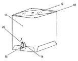
本発明は、弁を具えた取出機構(図3及び図4参照)、及び弁を具えた取出機構を有する保護ケース入り袋(図1参照)に関する。
保護ケース入り袋は、外側を剛性の堅い容器つまり保護ケース(10)で構成し、その中に、適当な可撓性材料で作られた可撓性袋(12)が配置されている。剛性の外側容器を形成するために適当な容器として、マクミランブローデルバルクパッケージングにより、商標名「SpaceKraftTM」で販売されている容器を挙げることができる。これらの外側容器は断面矩形の管状であり、片面が波形の資材が複数の層に巻き付けられている。しかしながら、本発明は、外側容器として、その他の剛性容器を用いることもできる。
外側の堅い容器(10)には、孔(14)が、壁の1つ(図示の構成では壁(16))を貫通して開設され、取出機構(20)の突出部(18)が通る通路(14)を形成している。
【0016】
図2並びに、より詳細に示す図3及び図4を参照すると、取出機構(20)は本体部(22)を含んでおり、本体部は突出部(18)を有し、該突出部には、液体等の内容物を取り出すための通路(24)が突出部(18)の軸方向を貫通して形成されている。本体部(22)(後で説明する)には、シャフトを収容する軸孔(26)も形成されている。内部の液体の取出し又は流通を行なうための通路(24)とシャフト収容用軸孔(26)の長手方向の軸線(28)(30)は、少なくとも通路(24)の端部でほぼ平行(図3参照)である。通路(24)は本体部(22)の横断面領域の実質的部分を占めており、この領域は外側容器(10)を通る孔(14)の領域の実質的部分を占めていることは明らかであろう。
【0017】
円環状の取付用フランジ(32)は、本体部(22)の軸方向の内側端部にて、通路(24)(即ち、本体部(22)の突出部(18)から)から半径方向に延びている。このフランジ(32)は、符号(34)(図2)で示すように、本体部(22)の全周にて、溶接その他の方法により、袋へ取り付けられており、通路(24)を完全に取り囲んでシールされる。取出機構(20)の突出部(18)は、袋体(12)(図2参照)の孔(33)を貫いて延びており、フランジ(32)は袋体(12)の内側に配置される。つまり、フランジ(32)の外側表面(35)は、袋体(12)の内側表面(13)と向かい合って取り付けられ、内側表面(13)との間はシールされている(図2参照)。
【0018】
下記に説明する弁の操作が妨げられない場合には、取出機構(20)を袋(12)の外側に取り付けることも可能である。
図2、図3及び図4に示されるように、フランジ(32)の肉厚は、外側部(36)が薄く、内側部(38)(小径側)が厚くなっている。図示の構成において、薄肉部(36)の外側表面(35)は、溶接その他の方法により、袋(12)の内側表面(13)へ取り付けられ、袋(12)の孔(33)の周囲がシールされる(図2参照)。フランジ(32)の厚肉で可撓性に乏しい部分(38)の内側表面(40)は、弁板(42)と協働作用する表面(40)であり、通路(24)は、弁板(42)と表面(40)によって密閉される。
【0019】
本体部(22)には、フランジ(32)の側で、内側表面(40)から離れた位置にて、フランジ(32)から軸方向に間隔をあけて第2の径方向フランジ(44)が設けられる。このフランジ(44)はフランジ(32)と共に、円筒部(46)を支持している。この円筒部(46)は、フランジ(32)(44)の間を通り、フランジ(44)から外方に突出している。軸孔(26)は円筒部(46)を貫いて形成される。シャフト(48)は軸孔(26)の中を通り、Oリング(47)はシャフト(48)の周囲のシール体として供される。シャフト(48)の軸方向両端部は、横断面が正方形又は矩形の部分(49)(51)に形成されることが望ましい。これは、シャフト(48)の内側の端部の部分(49)に対応する形状に形成された弁板(42)の孔(53)に、部分(49)を嵌めて、シャフト(48)と弁板(42)とが回転可能に連結されるようにすると共に、また、シャフト(47)の外側端部の部分(51)に対応する形状に形成されたレバー(50)のソケット(52)に、部分(51)を嵌めて、シャフト(48)とレバー(50)とが回転可能に連結されるようにすることを容易ならしめるためである。
【0020】
弁板(42)は、適当な方法であればどんな方法でもシャフトへ固定されることができる。図示の構成では、弁板(42)は、シャフト(48)の軸孔(57)にねじ込まれたボルト(55)によってシャフト(48)へ取り付けられている。レバー(50)は、必要に応じて、断面形状が正方形の部分(51)と着脱可能にすることができる。
弁板(42)とフランジ(32)は、弁板(42)が閉位置にあるとき、通路(24)を塞ぐ密閉手段を形成するようになっている。図示の構成において、弁板(42)には、Oリングシール(56)が嵌まる環状溝(54)が形成されており、該Oリングはフランジ(32)の内側表面(40)と協働作用するものであり、弁板(42)が通路(24)の開位置から閉位置へ移動して通路(24)をシールする。このとき、Oリング(56)は通路(24)の外周部を取り囲んでシールを形成する。
【0021】
弁板(42)をフランジ(32)の内側表面(40)に位置決めする際、その調節をより都合良く行なうために、略L字状のガイド要素(58)が設けられている。このガイド要素(58)は、通路(24)の側でシャフト(48)とは反対側にて、通路(24)の周方向をその一部分だけ延びており、案内用の通路又は溝(60)を形成している。案内用通路(60)は、L字状要素(58)の突条(62)と、フランジ(32)の内側表面(40)の間に形成される。外周(64)に隣接する弁板(42)は、閉位置にあるとき、案内通路(60)の中に入るから、弁板(42)は閉位置で保持され、Oリング(56)は表面(40)との間にシールを形成する。つまり、突条(62)と表面(40)との間の間隔は、プレート(42)の厚さとOリング(56)の突出厚さの和となるように調整され、表面(40)に当接してクランプされたOリングが保持される。溝の長さは、後記するように、弁板(42)がシャフト(48)の長軸と平行して移動するように調整され、Oリング(56)が表面(40)に当たる位置へ移動したとき、シャフト(48)から離れた位置にある弁板(42)の外周部が溝に入る。必要に応じて、弁板(42)の外周部が進入する溝(60)の入口端部をフレア状に拡げておくことにより、弁板(42)が閉位置へ移動したときに、当該部分が嵌まった後、シャフト(48)の軸と平行な移動が行われるようにすることができる。弁板(42)が閉位置に完全に達すると、溝は、弁板(42)を表面(40)の方へ付勢する。
【0022】
通路(26)に隣接する表面(40)の適当な位置に係止部(66)を突設することにより、弁板(42)が全開の位置まで回転したとき、弁板(42)の側縁に係合させて、その方向へさらに移動するのを抑えることができる。
袋体(12)が外側容器(10)の中に入れられ、袋(12)と保護ケース(10)に内容物が満たされた後、弁板(42)は閉じられる。望ましくは、図2、図3及び図4の符号(70)で示される適当なキャップ又はプラグが、キャップ(70)のネジ部(72)(及び、通路(24)のネジ部)を介して、通路(24)の中へ螺合される。Oリング(74)は、キャップ(70)のフランジ(76)と、本体部(22)の通路(24)を取り囲む前端面(78)との間でクランプされることが望ましい。それゆえ、キャップ(70)は、輸送又配送中、取出機構の第2のシールとなる。
【0023】
取出機構(20)は、カム部材とその協働カム部材とによって形成される一対のカムが2組設けられており、カム部材の作用により、弁板(42)は取出機構(20)の軸方向を表面(40)の方へ移動させられ、通路(24)が密閉される。これについては、後で説明する。この軸方向の動きによって、Oリングシール(56)は表面(40)へ押し当てられて、通路(24)の周りでシールを形成すると共に、弁板(42)が開位置へ移動すると、弁板(42)を表面(40)から引き離す。これは、2組のカム部材が作用して達成され、シャフト(48)の回転により、弁板(42)が開位置と閉位置との間を移動するとき、シャフト(48)、ひいては弁板(42)を、シャフト(48)の長軸に関して、つまりシャフト(48)を取出機構(20)の本体部(22)に関して、軸方向に移動させる。
【0024】
図示の構成において、取出機構(20)の本体部(22)に関する弁板(42)の軸方向の移動は、第1のカム(90)と第2のカム(92)の2組のカムの作用によって行われる。第1のカム(90)と第2のカム(92)は、夫々、カム部材と協働カム部材とによって構成される。2つのカム部材のうち一方のカム部材を構成する第1のカム部材(100)は、弁板(42)の上にて、シャフト(48)用の孔(53)を部分的に取り囲み、フランジ(32)の外側と面するように形成される。2つのカム部材のうち他方のカム部材を構成する第2のカム部材(102)もまた、フランジの外側、つまり取出機構(20)の端部と面しており、円筒部(46)の軸方向端部に配置され、シャフト(48)が通る孔(26)を部分的に取り囲んでいる(つまり、カム部材(100)と(102)はシャフト(48)と同軸上にある)。
【0025】
内向きの協働カム部材(104)(106)は、夫々、表面(40)の上と、シャフト(48)の一体部分である大径の係止部(108)の上に形成される。協働カム部材(104)(106)は、各々が、シャフト(48)を部分的に取り囲み、シャフト(48)と同軸上にあり、取出機構の組立て完了状態では、夫々、カム部材(100)(102)と協働作用する関係に配置される。
カム(100)と(104)は、対となって第1のカム(90)を形成し、カム部材(102)と(106)は、第2のカム(92)を形成する。
【0026】
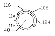
カム部材(100)(104)及び協働カム部材(102)(106)には、夫々に、(110)(112)(114)(116)で示される傾斜面が形成されており、各傾斜面は、カム部材が形成される主要面から遠ざかるにつれて傾斜し、夫々、(118)(120)(112)(124)で示される凸面に繋がっている。傾斜面は、取出機構(20)の夫々の表面に対して略同じ角度で傾斜しており、角度αで取り付けられる。図示の実施例において、凸面(120)(122)(124)は、取出機構(10)の距離Xをあけて取り付けられた部分に関して外方へ突出している。
Xは一般的に0.01〜0.06インチの範囲であり、αは一般的に約0.65〜4Oの範囲である。
【0027】
Oリング、例えばOリング(56)が通路(24)をシールするために用いられるとき、カム部材(100)は、弁板(42)が閉位置にあるときに圧力がOリングへ作用するように特別に構成される。前述したカム部材(100)は凸面(118)を有し、図5の左側には、傾斜面(100)を有している。しかしながら、傾斜面は、弁板(42)の表面で終端する代わりに、斜面(110)から凸面(118)の右側つまり端部へ延びる円形溝(126)へ繋がっている。この溝(126)は、深さがY(図10参照)であり、望ましい実施例における凸面(118)は溝(126)の底部から距離Xだけ突出している。この構造は、弁板(42)の面(130)の間隔は(図3、図9及び図10参照)、弁板(42)が開位置にあるとき、2X−Yであり、弁板(42)が閉位置にあるとき、X−Y=Zインチであることを意味している。Zは、Oリング(56)が面(130)から突出する量より僅かに少なく、閉位置において、Oリングはシールを形成するのに必要とされる程度に圧縮される。
【0028】
具体的実施例において、Xは0.03インチ、Yは0.02インチ、Zは0.01インチであり、Oリング(56)へ圧力が加えられ、αは1.95Oであった。
図示した前述のデュアルアクティングカムが望ましい。なお、シャフト(48)と弁板(42)が回転して閉位置になるとき、シャフト(48)の長軸と平行な方向へ弁板(42)を移動させ、シャフト(48)と弁板(42)が反対方向に回転して開位置になるとき、弁板(42)を反対方向へ移動させることができるものであれば、シャフト(48)と通路(26)で螺合するネジ、溝とピンの組合せのような他のデュアルアクティングカムを用いることができるであろう。
【0029】
次に、作用について説明する。弁板(42)が閉位置にあるとき(図9及び図10参照)、カム部材(100)(104)の凸面(118)(120)は、溝(126)にある凸面(120)とは、ずれた位置関係にあるのに対し、協働カム部材(102)(106)の凸面(122)(124)は、当接する位置関係にあり、シャフト(48)、ひいてはシャフト(48)に軸支された弁板(42)を表面(40)の方へ移動させて、Oリング(56)を表面(40)に当ててクランプする。弁板(42)が表面(40)へ移動すると、シャフト(48)から離れた位置にある弁板(42)の外周部(64)は溝(60)の中に入る。弁板(42)の閉位置への移動が完了するとき、弁板(42)の自由端部は適当な位置に入り込んでおり、このときOリング(56)は表面(40)に押しつけられている。前述のように、溝(60)の入口端部をフレア状に拡げることもできるが、その場合には、弁板(42)の表面(40)への移動が完了する前に外周部(64)が溝(60)の中に進入するから、溝(60)は弁板(42)の自由端部を表面(40)へ当接させるカム手段として作用する。
【0030】
一方、シャフト(48)の回転により、弁板(42)が開位置へ移動すると、カム部材(100)(104)の凸面(118)(120)が当接し、カム部材(102)(106)の凸面(122)(124)は、ずれた位置関係となり、弁板(42)は表面(40)から離れる方向に移動する。
本発明の作用は明瞭であろう。取出機構(20)は袋体(12)に取り付けられており、袋は保護ケースである外側容器(10)の中へ入れられる。このとき、取出機構(20)は保護ケース(10)の通路(14)の中を通される。取出機構(20)は、保護ケース(10)の外側を越えて突出しないことが望ましい(但し、保護ケースを越えて突出する場合もある)。プラグ又はキャップ(70)は通路の中へねじ込まれて通路をシールし、弁板(42)は通路(24)の内側端部を閉じる閉位置へ移動するので、通路(24)は、一方の端部が弁板(42)により、他方の端部がプラグ(70)により、両端部に2つのシールが形成される。取出機構(20)がシールされ、袋(12)が保護ケース(10)の中に配置された後、袋(12)には、通路(24)を通って流れる液体又は流体等の材料が入れられる。保護ケース(10)に入れられた袋(12)は閉じられて、消費者の元へ発送される。
【0031】
消費者の元へ到着すると、プラグ(70)が取り外され(このとき、弁板(42)は閉位置にあり、通路(24)は閉じたままである)、取出機構(20)は、ホース等にの手段により、所望の位置へ繋がれる。
この装置を使用する場合、レバー(50)をシャフト(48)の端部(51)へ取り付けて、シャフト(48)を回転させる必要があり、カム(90)(92)により、シャフト(48)を軸方向へ移動させて、弁板(42)を開位置へ移動させる。このとき、弁板(42)は、表面(40)とは間隔を有し、通路(24)から離れており、通路(24)の中での流通が可能となる。流れを遮断したい場合、シャフト(48)を再び回転させるだけでよく、弁板(42)は閉位置へ戻され、カム(90)(92)を介してシャフト(48)を反対方向へ軸方向移動させ、弁板(42)を表面(40)へ移動させて、通路(24)を塞ぎ、通路(24)が密閉される。
【0032】
本発明を説明したが、当該分野の専門家であれば、特許請求の範囲に規定された発明の範囲から逸脱することなく種々の変形をなすことができる。
【図面の簡単な説明】
【図1】本発明の弁付取出機構を具える保護ケース入り袋の概要を示す斜視図である。
【図2】図1の2−2線に沿う断面図である。
【図3】弁付取出機構とそれに用いられるプラグを、取出機構の一方の軸方向端部から見た分解斜視図である。
【図4】図3と同様な分解斜視図であって、弁付取出機構とそれに用いられるプラグを、取出機構の他方の軸方向端部から見た図である。
【図5】弁本体を一方の軸端部から見た図であって、弁板を作動させるカム部材を示している。
【図6】弁本体を図5と反対側の軸端部から見た図であって、図5のカム部材の協働カム部材を示している。
【図7】図5と同様な図であって、弁板を軸方向へ移動させる第2のカム部材を示している。
【図8】図6と同様な図であって、弁板を軸方向へ移動させる第2の協働カム部材を示している。
【図9】図5及び図6の9−9線上のカムを切断して示す分解断面図であって、第1のカム部材はシール板の上、協働カム部材は本体部フランジの上にあり、弁が閉位置にあるときの状態を示している。
【図10】図9と同様に、9−9線に沿う分解断面図であって、第1のカム部材はシール板の上、他方の協働カム部材は本体部フランジの上にあり、弁が開位置にあるときの状態を示している。
【図11】図7及び図8の11−11線上のカムを切断して示す分解断面図であって、第2のカム部材は本体の円筒部の外側の軸端部にあり、他方の協働カム部材は作動シャフトを介してシール板へ取り付けられており、弁が閉位置にあるときの状態を示している。
【図12】図11と同様に、11−11線に沿う分解断面図であって、第1のカム部材は本体の円筒部の外側の軸端部にあり、他方の協働カム部材は作動シャフトを介してシール板へ取り付けられており、弁が開位置にあるときの状態を示している。
【符号の説明】
(10) 外側容器又は外側ケース
(12) 袋又は袋体
(20) 取出機構
(22) 本体部
(24) 通路
(32) フランジ
(40) 内側表面
(42) 弁板
(48) シャフト[0001]
BACKGROUND OF THE INVENTION
The present invention relates to a bag and box combination in which a bag is placed in a protective case (box). More specifically, the present invention relates to a bag with a protective case having an improved valve mechanism. This bag with a protective case may be referred to as a bag-in-box.
[0002]
[Prior art and problems to be solved by the invention]
Protective cased bags typically have some form of fitment attached to the bag, and the takeout mechanism passes through an opening formed in the side wall of the rigid outer case. . During delivery, the passage of the take-out mechanism is sealed. The passage is sealed, for example, by welding with a membrane or on the inside of the mounting flange of the take-out mechanism, that is, on the mounting flange away from the outer case. Therefore, the bag actually covers the passage through the removal mechanism. In many cases, the outlet is sealed during delivery by attaching a cap or a plug or the like to the membrane for the extraction mechanism and the exposed end of the extraction mechanism.
[0003]
During transport or delivery, the protective cased bag is sealed by these sealing means, but in order to remove material (eg, liquid) from the bag, it is necessary to open a passage through the removal mechanism. This opening operation is generally performed using an external valve. This external valve is fixed to the take-out mechanism instead of a cap or a plug, and a means for making a hole in a bag or a membrane for sealing the passage of the take-out mechanism is provided.
[0004]
These mechanisms are very difficult to handle and require a control valve to be installed where the bag contents should be removed. This valve remains attached until the bag is empty, making it more difficult to move the protective cased bag. It is also possible to transport or deliver the bag and valve as a unit by attaching the valve to an appropriate position. However, since a larger pallet is necessary, there is a risk of increased costs and leakage during transportation. Will also increase.
[0005]
Gate valves used for rigid cases have been known for some time. For example, U.S. Pat. No. 88008 granted to Chaise et al. On March 23, 1869, U.S. Pat. No. 5,218,932 issued Jun. 26, 1894, granted to Mr. Howe et al. On October 10, 1899 Reference may be made to U.S. Pat. No. 634730, and more recently U.S. Pat. No. 3,321,175 issued May 23, 1967.
[0006]
The plate or gate valve described in the Chaise et al. Patent is pivotally supported on a rigid shaft axis, and the position of the plate is adjusted by moving between an open position and a closed position by rotation. This is common to all the above patents. Furthermore, all of the above patents attach the valve to a rigid body (opposite the flexible bag) so that the valve plate can be moved from the open position to the closed position without interfering with the connected structure. Can be easily moved to.
[0007]
In the device provided by Chaes et al., The valve plate is housed inside a rigid block, and the movement of the valve plate is limited by the block to the width of the block structure. In this case, the block structure must be large enough to accommodate the valve plate in both the open and closed positions while the valve plate moves. As such, the device is relatively bulky and often not effective for many purposes.
[0008]
[Means for Solving the Problems and Effects of the Invention]
The object of the present invention is to provide a novel valve structure which is particularly suitable for use in a bag encased in a protective case.
An object of the present invention is to provide a bag with a protective case having a take-out mechanism in which a valve is incorporated.
[0009]
In a broad sense, the present invention relates to a take-out mechanism with a valve, a main body part in which a passage is formed in the axial direction, an annular radial flange formed in the main body part and surrounding the inner end of the passage; A valve plate, a shaft that rotatably attaches the valve plate to the main body, and a dual acting cam for moving the valve plate in the same direction as the long axis of the shaft (parallel), The valve plate can be rotated around the shaft together with the shaft, and the long axis of the shaft is parallel to the long axis of the axial passage and the inner end thereof, and is spaced from one side of the axial passage. When the valve plate is in the closed position due to the rotation of the shaft, the axial passage is sealed. When the valve plate is in the open position due to the rotation of the shaft, the axial passage is opened. Connected first cam means Cooperating cam means attached to the body portion, the first cam means and the cooperating cam means surface the valve plate when the valve means is rotated to the closed position by the shaft. When the valve plate is rotated to the open position, it acts to move the valve plate away from the surface.
[0010]
In a broad sense, the present invention relates to a bag with a protective case, which is a container having a hard wall on the outside and a flexible bag housed inside the container. When the body is filled, the body is supported by the rigid wall of the container, the bag body is attached with an extraction mechanism, and the container is formed with a hole penetrating the rigid wall, the hole being removed A passage through which the projecting portion of the mechanism passes, and the take-out mechanism includes a main body portion in which the passage is formed in the axial direction, an annular radial flange formed in the main body portion and surrounding the inner end portion of the passage; A valve plate and a shaft that rotatably attaches the valve plate to the main body, the valve plate being configured to be able to rotate around the shaft together with the shaft, the long axis of the shaft being the long axis of the axial passage; Parallel at its inner end and spaced from one side of the axial passage And is, valve plate, at the closed position by rotation of the shaft, sealing the axial passage when in the open position by rotation of the shaft, opening the axial passage.
[0011]
A desirable take-out mechanism comprises a dual actuating cam for moving the valve plate in the same direction as the long axis of the shaft, the dual actuating cam comprising a first cam means connected to the valve plate, and a body portion. Cooperating cam means attached to the first cam means and cooperating cam means for moving the valve plate toward the surface when the valve means is rotated to the closed position by the shaft; When the is rotated to the open position, it acts to move the valve plate away from the surface.
[0012]
The first cam means includes a pair of cam members coaxial with the shaft means, and the first cam member is disposed adjacent to the inner end portion of the shaft and one axial end portion of the main body portion. The second cam member is disposed on a side opposite to the surface of the main body portion at a position axially spaced from the inner end portion of the shaft, and the cooperative cam means includes a pair of cooperative cam members. Each cooperating cam member is preferably arranged to cooperate adjacent to the pair of cam members to positively move the valve plate axially with respect to the long axis of the shaft means. .
[0013]
Each of the cam members of the pair of cam members and each of the collaborative cam members of the pair of cam members includes a convex surface and an inclined surface connected to the convex surface, and the convex surface of the first cam member and the cooperative cam member thereof When the valve plate is in the open position, the convex surfaces of the second cam member and the cooperating cam member are displaced when the valve plate is in the open position. (offset relationship) is desirable.
[0014]
It is desirable to connect the annular flange to the bag by connecting the outer surface of the annular flange to the inner surface of the bag.
It is desirable to have an O-ring gasket attached to the valve plate, having a diameter greater than the diameter of the axial passage and surrounding the axial passage when the valve plate is in the closed position.
It is desirable to provide a guide for guiding the valve plate to the closed position at an appropriate position on the mounting flange so as to engage the outer periphery of the valve plate on the side of the axial passage away from the shaft.
It is desirable that the main body portion further includes a locking portion protruding from the cooperating surface to the bag adjacent to the shaft, and the locking portion is arranged so that the valve plate does not move in the direction away from the closed position. Is done.
Further features, objects and advantages will become more apparent from the detailed description of the preferred embodiment of the invention as set forth in conjunction with the accompanying drawings.
[0015]
DETAILED DESCRIPTION OF THE INVENTION
The present invention relates to a take-out mechanism (see FIGS. 3 and 4) having a valve, and a protective case-containing bag (see FIG. 1) having the take-out mechanism having a valve.
The outer bag of the protective case is composed of a rigid, rigid container or protective case (10), and a flexible bag (12) made of a suitable flexible material is disposed therein. Suitable containers for forming a rigid outer container may include containers sold under the trade name “SpaceKraft ™ ” by Macmillan Brodel bulk packaging. These outer containers are tubular with a rectangular cross section, and a corrugated material on one side is wound around a plurality of layers. However, the present invention can use other rigid containers as the outer container.
In the outer rigid container (10), a hole (14) is opened through one of the walls (in the configuration shown, wall (16)) through which the protrusion (18) of the extraction mechanism (20) passes. A passage (14) is formed.
[0016]
Referring to FIG. 2 and FIGS. 3 and 4 shown in more detail, the take-out mechanism (20) includes a body portion (22), and the body portion has a protrusion (18), A passage (24) for taking out contents such as liquid is formed through the axial direction of the protrusion (18). A shaft hole (26) for accommodating a shaft is also formed in the main body (22) (described later). The passage (24) for taking out or distributing the liquid inside and the longitudinal axis (28) (30) of the shaft accommodating shaft hole (26) are substantially parallel at least at the end of the passage (24) (see FIG. 3). It is clear that the passage (24) occupies a substantial part of the cross-sectional area of the body (22), which occupies a substantial part of the area of the hole (14) through the outer container (10). Will.
[0017]
An annular mounting flange (32) extends radially from the passage (24) (i.e., from the protrusion (18) of the main body (22)) at the axially inner end of the main body (22). It extends. The flange (32) is attached to the bag by welding or other methods around the entire circumference of the main body (22) as shown by reference numeral (34) (FIG. 2), and the passage (24) is completely formed. Surrounded and sealed. The protrusion (18) of the take-out mechanism (20) extends through the hole (33) of the bag (12) (see FIG. 2), and the flange (32) is disposed inside the bag (12). The That is, the outer surface (35) of the flange (32) is attached so as to face the inner surface (13) of the bag body (12), and is sealed between the inner surface (13) (see FIG. 2).
[0018]
If the operation of the valve described below is not hindered, the takeout mechanism (20) can be attached to the outside of the bag (12).
As shown in FIGS. 2, 3, and 4, the thickness of the flange (32) is such that the outer part (36) is thin and the inner part (38) (small diameter side) is thick. In the illustrated configuration, the outer surface (35) of the thin wall portion (36) is attached to the inner surface (13) of the bag (12) by welding or other methods, and the periphery of the hole (33) of the bag (12) is Sealed (see FIG. 2). The inner surface (40) of the thick and inflexible portion (38) of the flange (32) is a surface (40) that cooperates with the valve plate (42), and the passage (24) is the valve plate. Sealed by (42) and surface (40).
[0019]
The body (22) has a second radial flange (44) spaced axially from the flange (32) at a position away from the inner surface (40) on the flange (32) side. Provided. The flange (44) supports the cylindrical portion (46) together with the flange (32). The cylindrical portion (46) passes between the flanges (32) and (44) and protrudes outward from the flange (44). The shaft hole (26) is formed through the cylindrical portion (46). Shaft (48) passes through the shaft hole (26), O-ring (47) is provided as a seal member surrounding the shaft (48). It is desirable that both end portions in the axial direction of the shaft (48) are formed in portions (49) and (51) having a square or rectangular cross section. This is because the portion (49) is fitted into the hole (53) of the valve plate (42) formed in a shape corresponding to the inner end portion (49) of the shaft (48), and the shaft (48) The valve plate (42) is rotatably connected to the socket (52) of the lever (50) formed in a shape corresponding to the outer end portion (51) of the shaft (47). In order to make it easy to fit the portion (51) to the shaft (48) and the lever (50) so as to be rotatably connected to each other.
[0020]
The valve plate (42) can be secured to the shaft in any suitable manner. In the illustrated configuration, the valve plate (42) is attached to the shaft (48) by a bolt (55) screwed into the shaft hole (57) of the shaft (48). The lever (50) can be attached to and detached from the portion (51) having a square cross-sectional shape as necessary.
The valve plate (42) and the flange (32) form a sealing means for closing the passage (24) when the valve plate (42) is in the closed position. In the illustrated configuration, the valve plate (42) is formed with an annular groove (54) into which the O-ring seal (56) is fitted, and the O-ring cooperates with the inner surface (40) of the flange (32). The valve plate (42) moves from the open position of the passage (24) to the closed position to seal the passage (24). At this time, the O-ring (56) surrounds the outer periphery of the passage (24) to form a seal.
[0021]
In order to make the adjustment more convenient when positioning the valve plate (42) on the inner surface (40) of the flange (32), a substantially L-shaped guide element (58) is provided. This guide element (58) extends in the circumferential direction of the passage (24) only partly on the side of the passage (24) opposite to the shaft (48), and is a guide passage or groove (60). Is forming. The guide passage (60) is formed between the protrusion (62) of the L-shaped element (58) and the inner surface (40) of the flange (32). When the valve plate (42) adjacent to the outer periphery (64) enters the guide passage (60) when in the closed position, the valve plate (42) is held in the closed position and the O-ring (56) is on the surface. A seal is formed with (40). In other words, the distance between the protrusion (62) and the surface (40) is adjusted to be the sum of the thickness of the plate (42) and the protrusion thickness of the O-ring (56), so that it contacts the surface (40). The O-ring clamped in contact is held. The length of the groove was adjusted so that the valve plate (42) moved in parallel with the long axis of the shaft (48), and the O-ring (56) moved to a position where it hits the surface (40), as will be described later. At this time, the outer peripheral portion of the valve plate (42) located away from the shaft (48) enters the groove. If necessary, when the valve plate (42) moves to the closed position, the inlet end of the groove (60) into which the outer periphery of the valve plate (42) enters is flared. After fitting, the movement parallel to the axis of the shaft (48) can be performed. When the valve plate (42) reaches the closed position completely, the groove biases the valve plate (42) towards the surface (40).
[0022]
When the valve plate (42) is rotated to the fully open position by protruding the locking portion (66) at an appropriate position on the surface (40) adjacent to the passage (26), the valve plate (42) side Engaging with the edge can prevent further movement in that direction.
After the bag body (12) is placed in the outer container (10) and the bag (12) and the protective case (10) are filled with contents, the valve plate (42) is closed. Desirably, a suitable cap or plug, indicated by reference numeral (70) in FIGS. 2, 3 and 4, is passed through the threaded portion (72) of the cap (70) (and the threaded portion of the passage (24)). And screwed into the passage (24). The O-ring (74) is preferably clamped between the flange (76) of the cap (70) and the front end surface (78) surrounding the passage (24) of the main body (22). Therefore, the cap (70) provides a second seal for the removal mechanism during transport or delivery.
[0023]
The take-out mechanism (20) is provided with two pairs of cams formed by a cam member and its cooperating cam member, and the valve plate (42) is attached to the shaft of the take-out mechanism (20) by the action of the cam member. The direction is moved towards the surface (40) and the passage (24) is sealed. This will be described later. This axial movement forces the O-ring seal (56) against the surface (40) to form a seal around the passage (24) and when the valve plate (42) moves to the open position, Pull the plate (42) away from the surface (40). This is achieved by the action of two sets of cam members, and when the valve plate (42) moves between an open position and a closed position due to rotation of the shaft (48), the shaft (48) and thus the valve plate (42) is moved in the axial direction with respect to the long axis of the shaft (48), that is, with respect to the main body (22) of the take-out mechanism (20).
[0024]
In the configuration shown in the drawing, the axial movement of the valve plate (42) with respect to the main body (22) of the take-out mechanism (20) is caused by the two cams of the first cam (90) and the second cam (92). Done by action. The first cam (90) and the second cam (92) are each constituted by a cam member and a cooperative cam member. The first cam member (100) that constitutes one of the two cam members partially surrounds the hole (53) for the shaft (48) on the valve plate (42) and has a flange. (32) is formed so as to face the outside. The second cam member (102) constituting the other of the two cam members also faces the outside of the flange, that is, the end of the take-out mechanism (20), and the shaft of the cylindrical portion (46). Located at the directional end and partially surrounding the hole (26) through which the shaft (48) passes (ie, the cam members (100) and (102) are coaxial with the shaft (48)).
[0025]
The inward cooperative cam members (104) (106) are formed on the surface (40) and on the large-diameter locking portion (108) which is an integral part of the shaft (48), respectively. The cooperating cam members (104) (106) each partially surround the shaft (48) and are coaxial with the shaft (48), and the cam members (100) are respectively in the assembled state of the take-out mechanism. (102) is arranged in a cooperative working relationship.
The cams (100) and (104) are paired to form a first cam (90), and the cam members (102) and (106) form a second cam (92).
[0026]
The cam members (100) (104) and the cooperating cam members (102) (106) are formed with inclined surfaces indicated by (110) (112) (114) (116), respectively. The surfaces incline as they move away from the main surface on which the cam member is formed, and are connected to the convex surfaces indicated by (118) (120) (112) (124), respectively. The inclined surfaces are inclined at substantially the same angle with respect to the respective surfaces of the take-out mechanism (20), and are attached at an angle α. In the illustrated embodiment, the convex surfaces (120), (122) and (124) project outward with respect to the portion of the take-out mechanism (10) attached at a distance X.
X is generally in the range of 0.01 to 0.06 inches and α is generally in the range of about 0.65 to 4 O.
[0027]
When an O-ring, such as an O-ring (56) is used to seal the passage (24), the cam member (100) causes pressure to act on the O-ring when the valve plate (42) is in the closed position. Specially configured. The cam member (100) described above has a convex surface (118), and on the left side of FIG. However, instead of terminating at the surface of the valve plate (42), the inclined surface is connected to a circular groove (126) extending from the inclined surface (110) to the right side or the end of the convex surface (118). The groove (126) has a depth Y (see FIG. 10), and the convex surface (118) in the preferred embodiment projects a distance X from the bottom of the groove (126). In this structure, the distance between the faces (130) of the valve plate (42) (see FIGS. 3, 9 and 10) is 2X-Y when the valve plate (42) is in the open position, When 42) is in the closed position, it means that XY = Z inches. Z is slightly less than the amount the O-ring (56) protrudes from the face (130), and in the closed position, the O-ring is compressed to the extent required to form a seal.
[0028]
In a specific example, X was 0.03 inches, Y was 0.02 inches, Z was 0.01 inches, pressure was applied to the O-ring (56), and α was 1.95 O.
The previously described dual acting cam shown is desirable. When the shaft (48) and the valve plate (42) rotate to the closed position, the valve plate (42) is moved in a direction parallel to the long axis of the shaft (48), and the shaft (48) and the valve plate are moved. If the valve plate (42) can be moved in the opposite direction when the (42) rotates in the opposite direction, the screw screwed in the shaft (48) and the passage (26), Other dual-acting cams such as a groove and pin combination could be used.
[0029]
Next, the operation will be described. When the valve plate (42) is in the closed position (see FIGS. 9 and 10), the convex surfaces (118) and (120) of the cam members (100) and (104) are different from the convex surface (120) in the groove (126). The convex surfaces (122) and (124) of the cooperative cam members (102) and (106) are in contact with each other, and the shafts (48) and eventually the shaft (48) are axially aligned. The supported valve plate (42) is moved toward the surface (40), and the O-ring (56) is applied to the surface (40) and clamped. When the valve plate (42) moves to the surface (40), the outer peripheral portion (64) of the valve plate (42) located away from the shaft (48) enters the groove (60). When the movement of the valve plate (42) to the closed position is completed, the free end of the valve plate (42) has entered an appropriate position. At this time, the O-ring (56) is pressed against the surface (40). Yes. As described above, the inlet end of the groove (60) can be flared, but in that case, before the movement to the surface (40) of the valve plate (42) is completed, the outer peripheral portion (64 ) Enters the groove (60), the groove (60) acts as a cam means for bringing the free end of the valve plate (42) into contact with the surface (40).
[0030]
On the other hand, when the valve plate (42) is moved to the open position by the rotation of the shaft (48), the convex surfaces (118) (120) of the cam members (100) (104) come into contact with each other, and the cam members (102) (106) The convex surfaces (122) and (124) are displaced, and the valve plate (42) moves away from the surface (40).
The operation of the present invention will be clear. The take-out mechanism (20) is attached to the bag body (12), and the bag is put into the outer container (10) which is a protective case. At this time, the take-out mechanism (20) is passed through the passage (14) of the protective case (10). The take-out mechanism (20) preferably does not protrude beyond the outside of the protective case (10) (however, it may protrude beyond the protective case). The plug or cap (70) is screwed into the passage to seal the passage and the valve plate (42) moves to a closed position that closes the inner end of the passage (24) so that the passage (24) Two seals are formed at both ends by the valve plate (42) at one end and the plug (70) at the other end. After the take-out mechanism (20) is sealed and the bag (12) is placed in the protective case (10), the bag (12) is filled with a material such as liquid or fluid that flows through the passage (24). It is done. The bag (12) in the protective case (10) is closed and shipped to the consumer.
[0031]
When the consumer arrives, the plug (70) is removed (at this time, the valve plate (42) is in the closed position and the passage (24) remains closed), and the removal mechanism (20) is a hose, etc. It is connected to a desired position by means of (1).
When using this device, it is necessary to attach the lever (50) to the end (51) of the shaft (48) and rotate the shaft (48), and the cam (90) (92) Is moved in the axial direction to move the valve plate (42) to the open position. At this time, the valve plate (42) is spaced from the surface (40) and is separated from the passage (24), and can flow in the passage (24). If it is desired to shut off the flow, it is only necessary to rotate the shaft (48) again, the valve plate (42) is returned to the closed position and the shaft (48) is axially moved in the opposite direction via the cams (90) (92). The valve plate (42) is moved to the surface (40) to close the passage (24), and the passage (24) is sealed.
[0032]
Although the present invention has been described, it will be appreciated by those skilled in the art that various modifications can be made without departing from the scope of the invention as defined in the appended claims.
[Brief description of the drawings]
FIG. 1 is a perspective view showing an outline of a protective case-containing bag including a valved take-out mechanism of the present invention.
FIG. 2 is a cross-sectional view taken along line 2-2 of FIG.
FIG. 3 is an exploded perspective view of the take-out mechanism with a valve and the plug used there seen from one axial end of the take-out mechanism.
4 is an exploded perspective view similar to FIG. 3, and is a view of the valve-equipped take-out mechanism and the plug used there seen from the other axial end of the take-out mechanism. FIG.
FIG. 5 is a view of the valve main body as viewed from one shaft end portion, and shows a cam member that operates the valve plate.
6 is a view of the valve main body as seen from the shaft end opposite to that in FIG. 5 and shows a cooperative cam member of the cam member in FIG. 5;
7 is a view similar to FIG. 5, showing a second cam member for moving the valve plate in the axial direction. FIG.
8 is a view similar to FIG. 6, showing a second cooperating cam member for moving the valve plate in the axial direction.
9 is an exploded cross-sectional view of the cam taken along line 9-9 in FIGS. 5 and 6, wherein the first cam member is on the seal plate and the cooperative cam member is on the body flange. FIG. There is a state when the valve is in the closed position.
FIG. 10 is an exploded sectional view taken along line 9-9, similar to FIG. 9, wherein the first cam member is on the seal plate and the other cooperating cam member is on the main body flange; Shows the state when is in the open position.
11 is an exploded cross-sectional view showing the cam taken along the line 11-11 in FIGS. 7 and 8, wherein the second cam member is located at the outer shaft end portion of the cylindrical portion of the main body, and the other cooperative member. The working cam member is attached to the seal plate via the operating shaft, and shows the state when the valve is in the closed position.
12 is an exploded cross-sectional view taken along line 11-11, similar to FIG. 11, in which the first cam member is at the outer shaft end of the cylindrical portion of the main body and the other cooperating cam member is operated. It is attached to the seal plate via the shaft, and shows the state when the valve is in the open position.
[Explanation of symbols]
(10) Outer container or outer case
(12) Bag or bag
(20) Unloading mechanism
(22) Main unit
(24) Passage
(32) Flange
(40) Inner surface
(42) Valve plate
(48) Shaft
Claims (3)
前記取出機構は、本体部 (22) を含み、該本体部と突出部 (18) とを貫いて形成された軸方向通路 (24) を有しており、本体部(22) には通路の内側端部を取り囲む環状の径方向フランジ(32) が形成され、該フランジは、取出機構の軸方向通路の周りを袋体に密封するように袋体に取り付けられ、取出機構の突出部 (18) は容器の孔 (14) の中に進入しており、
取出機構は、弁板(42)と、該弁板を本体部に回動可能に取り付けるシャフト(48)を具え、該シャフトは、本体部 (22) を貫く軸孔 (26) の中に収容され、弁板はシャフトと共にシャフトの軸心の周りを回転できるようになし、
シャフトの軸心は、軸方向通路(24)の軸心と平行で、軸方向通路の側面と間隔を有しており、
弁板(42)は、シャフト(48)の回転によって閉位置になると、軸方向通路(24)を密閉し、シャフト(48)の回転によって開位置になると、軸方向通路(24)が開くようにしており、
第1カム手段 (90) と協働カム手段 (92) とを含むデュアルアクティングカムを具え、
第1カム手段 (90) は、本体部 (22) に、軸孔 (26) の内側端周囲にてカム部材 (104) が形成され、弁板 (42) に、前記カム部材 (104) と対向する位置にてカム部材 (100) が形成されており、
協働カム手段 (92) は、本体部 (22) に、軸孔 (26) の外側端周囲にて協働カム部材 (102) が形成され、シャフト (48) に、前記協働カム部材 (102) と対向する位置にて協働カム部材 (106) が形成されており、
デュアルアクティングカムは、シャフト (48) の回転により、弁板 (42) が軸方向通路 (24) を開く方向に移動すると、弁板 (42) は本体部 (22) から離間するように作用し、弁板 (42) が軸方向通路 (24) を閉じる方向に移動すると、弁板 (42) は本体部 (22) に接近するように作用する、
保護ケース入り袋。A bag placed in a protective case, the outer side being a container (10) having a hard wall, and the inner side being a flexible bag (12) accommodated in the container, the flexible bag When the interior is filled, it is supported by the rigid wall of the container, the take-out mechanism (20) is attached to the bag body, and the hole (14) penetrating the rigid wall is formed in the container. The hole constitutes a hole that accommodates the protrusion (18) of the take-out mechanism,
The takeout mechanism includes a body portion (22) has a projecting portion body portion (18) the axial passage (24) formed through the, passage in the body portion (22) An annular radial flange (32) is formed surrounding the inner end , and the flange is attached to the bag so as to seal the bag around the axial passage of the take-out mechanism, and the protrusion (18 ) Has entered the hole (14) of the container ,
The take-out mechanism includes a valve plate (42) and a shaft (48) for rotatably mounting the valve plate to the main body, and the shaft is accommodated in a shaft hole (26) that penetrates the main body (22). The valve plate can rotate around the shaft axis together with the shaft,
The axial center of the shaft is parallel to the axial center of the axial passage (24) and has a distance from the side surface of the axial passage,
When the valve plate (42) is closed by rotation of the shaft (48) , the axial passage (24) is sealed, and when the shaft (48) is opened by rotation of the shaft (48) , the axial passage (24) is opened. to have,
A dual actuating cam including first cam means (90) and cooperating cam means (92) ;
First cam means (90), the body portion (22), is formed a cam member (104) is at an inner end circumference of the axial hole (26), the valve plate (42), said cam member (104) The cam member (100) is formed at the facing position ,
Cooperating cam means (92), the body portion (22), cooperating cam member (102) at the outer end periphery of the shaft hole (26) is formed, on the shaft (48), said cooperating cam member ( A cooperative cam member (106) is formed at a position facing ( 102) ,
Dual Acting cam, the rotation of the shaft (48), the valve plate (42) moves in the direction of opening the axial passage (24), the valve plate (42) acts so as to be separated from the main body portion (22) When the valve plate (42) moves in the direction of closing the axial passage (24) , the valve plate (42) acts to approach the main body (22) .
Bag with protective case.
協働カム手段Collaborative cam means (92)(92) は、協働カム部材The cooperative cam member (102)(102) が凸面Is convex (122)(122) と該凸面に連なる傾斜面And an inclined surface connected to the convex surface (114)(114) を有し、協働カム部材Has a collaborative cam member (106)(106) が凸面Is convex (124)(124) と該凸面に連なる傾斜面And an inclined surface connected to the convex surface (116)(116) を有しており、Have
弁板Valve plate (42)(42) が開位置にあるとき、第1カム手段First cam means when is in the open position (90)(90) の凸面Convex surface (118)(118) と凸面And convex (120)(120) は対向し、協働カム手段Are opposed and cooperative cam means (92)(92) の凸面Convex surface (122)(122) と凸面And convex (124)(124) はずれた位置関係にあり、It is out of position,
弁板Valve plate (42)(42) が閉位置にあるとき、第1カム手段First cam means when is in the closed position (90)(90) の凸面Convex surface (118)(118) と凸面And convex (120)(120) はずれた位置関係にあり、協働カム手段Cooperating cam means that are out of position (92)(92) の凸面Convex surface (122)(122) と凸面And convex (124)(124) は対向する、請求項1の保護ケース入り袋。The bag with a protective case according to claim 1, which faces each other.
Applications Claiming Priority (2)
| Application Number | Priority Date | Filing Date | Title |
|---|---|---|---|
| US09/090995 | 1998-06-05 | ||
| US09/090,995 US5944300A (en) | 1998-06-05 | 1998-06-05 | Bag and box valve system |
Publications (2)
| Publication Number | Publication Date |
|---|---|
| JPH11349049A JPH11349049A (en) | 1999-12-21 |
| JP4262833B2 true JP4262833B2 (en) | 2009-05-13 |
Family
ID=22225256
Family Applications (1)
| Application Number | Title | Priority Date | Filing Date |
|---|---|---|---|
| JP15775999A Expired - Lifetime JP4262833B2 (en) | 1998-06-05 | 1999-06-04 | Valve device for bag with protective case |
Country Status (7)
| Country | Link |
|---|---|
| US (2) | US5944300A (en) |
| EP (1) | EP0962421B1 (en) |
| JP (1) | JP4262833B2 (en) |
| AT (1) | ATE305902T1 (en) |
| CA (1) | CA2272477A1 (en) |
| DE (1) | DE69927550T2 (en) |
| ES (1) | ES2248966T3 (en) |
Families Citing this family (16)
| Publication number | Priority date | Publication date | Assignee | Title |
|---|---|---|---|---|
| US5944300A (en) * | 1998-06-05 | 1999-08-31 | Macmillan Bloedel Packaging | Bag and box valve system |
| AT500874B1 (en) * | 2004-03-05 | 2006-11-15 | Hagleitner Hans Georg | ISSUE VALVE |
| US9222622B2 (en) * | 2007-11-26 | 2015-12-29 | Air Products And Chemicals, Inc. | Vessels with personnel access provisions |
| US20130292412A1 (en) * | 2012-05-04 | 2013-11-07 | International Paper Company | Bulk bin and bag dispensing apparatus |
| CN102797861B (en) * | 2012-08-28 | 2014-07-16 | 中联重科股份有限公司 | Stop valve and concrete conveying system |
| CN103075564B (en) * | 2013-01-21 | 2015-07-01 | 上海鸿研物流技术有限公司 | Foldable handle assembly, and valve and middle-sized bulk container provided with same |
| CA2926965A1 (en) | 2013-10-11 | 2015-04-16 | Gehl Foods, Llc | Food product dispenser and valve |
| DE112014005019T5 (en) * | 2013-10-31 | 2016-08-04 | Borgwarner Inc. | Rotating wastegate valve |
| KR200479109Y1 (en) * | 2014-05-23 | 2015-12-23 | 박등희 | Keeping box for toy |
| CA161168S (en) | 2014-08-29 | 2015-12-01 | Gehl Foods Inc | Valve |
| USD792164S1 (en) | 2014-08-29 | 2017-07-18 | Gehl Foods, Llc | Food dispenser |
| KR20170047296A (en) * | 2014-08-29 | 2017-05-04 | 겔 푸즈, 엘엘씨 | Food product dispenser and valve |
| USD798106S1 (en) | 2015-08-28 | 2017-09-26 | Gehl Foods, Llc | Valve |
| USD795029S1 (en) | 2015-08-28 | 2017-08-22 | Gehl Foods, Llc | Tool |
| FR3050788B1 (en) * | 2016-04-27 | 2018-11-23 | D-Innovation | TASTING VALVE |
| US10751647B1 (en) * | 2019-06-27 | 2020-08-25 | Kusters Zima Corporation | Sludge collection system for a clarifier |
Family Cites Families (15)
| Publication number | Priority date | Publication date | Assignee | Title |
|---|---|---|---|---|
| DE350287C (en) * | 1922-03-17 | Hans Hauerstein | Swivel slide | |
| US32354A (en) * | 1861-05-21 | Improved frjctional electric machine | ||
| US88008A (en) * | 1869-03-23 | Improvement in valves for bottoms of vessels | ||
| US521832A (en) * | 1894-06-26 | Steam-radiator | ||
| US634730A (en) * | 1899-08-23 | 1899-10-10 | Owatonna Mfg Company | Gate-valve for churns. |
| US1702998A (en) * | 1927-09-10 | 1929-02-19 | Foltis Anestis | Closure for collapsible tubes |
| US2604231A (en) * | 1949-08-27 | 1952-07-22 | Probstein Norton | Closure for collapsible dispensing tubes in the form of a pair of transversely swinging caps |
| US3321175A (en) * | 1964-11-23 | 1967-05-23 | Henderson Mfg Co Inc | Irrigation pipe gate |
| DE1950241A1 (en) * | 1969-10-06 | 1971-04-22 | Metallgesellschaft Ag | Shut-off device for pourable solid goods |
| DE2820531A1 (en) * | 1978-05-11 | 1979-11-15 | Leybold Heraeus Gmbh & Co Kg | ACTUATOR FOR VALVES, SLIDERS AND THE LIKE |
| CA1157068A (en) * | 1980-03-08 | 1983-11-15 | Sendair International Limited | Flow control valve assembly |
| US4603835A (en) * | 1983-11-09 | 1986-08-05 | The Perkin-Elmer Corporation | Shutter mechanism |
| US5425479A (en) * | 1994-06-15 | 1995-06-20 | The Coca-Cola Company | Valve for bag-in-box |
| US5673817A (en) * | 1995-04-05 | 1997-10-07 | Rapid Cartridge Dispensing Systems, Inc. | All-purpose dispenser for liquids such as milk, cream and juices, and bulk products such as condiments and salad dressings |
| US5944300A (en) * | 1998-06-05 | 1999-08-31 | Macmillan Bloedel Packaging | Bag and box valve system |
-
1998
- 1998-06-05 US US09/090,995 patent/US5944300A/en not_active Expired - Lifetime
-
1999
- 1999-05-21 CA CA002272477A patent/CA2272477A1/en not_active Abandoned
- 1999-05-28 US US09/321,601 patent/US6019253A/en not_active Expired - Lifetime
- 1999-06-03 AT AT99304337T patent/ATE305902T1/en not_active IP Right Cessation
- 1999-06-03 EP EP99304337A patent/EP0962421B1/en not_active Expired - Lifetime
- 1999-06-03 ES ES99304337T patent/ES2248966T3/en not_active Expired - Lifetime
- 1999-06-03 DE DE69927550T patent/DE69927550T2/en not_active Expired - Lifetime
- 1999-06-04 JP JP15775999A patent/JP4262833B2/en not_active Expired - Lifetime
Also Published As
| Publication number | Publication date |
|---|---|
| DE69927550T2 (en) | 2006-07-13 |
| JPH11349049A (en) | 1999-12-21 |
| CA2272477A1 (en) | 1999-12-05 |
| ATE305902T1 (en) | 2005-10-15 |
| ES2248966T3 (en) | 2006-03-16 |
| US6019253A (en) | 2000-02-01 |
| EP0962421B1 (en) | 2005-10-05 |
| EP0962421A1 (en) | 1999-12-08 |
| US5944300A (en) | 1999-08-31 |
| DE69927550D1 (en) | 2006-02-16 |
Similar Documents
| Publication | Publication Date | Title |
|---|---|---|
| JP4262833B2 (en) | Valve device for bag with protective case | |
| CA1319653C (en) | Binary syrup system bag and valve | |
| US11085804B2 (en) | Measuring adapter assembly for closed loop fluid transfer system | |
| JP2004524225A (en) | Connecting and closing device for dispensing valve assembly | |
| US9377111B2 (en) | Butterfly valve | |
| US8328042B2 (en) | Vessel port configured for use with a glove bag | |
| GB2468342A (en) | Connector assembly | |
| US5090658A (en) | Bellows sealed rotary valve and seal assembly | |
| GB2134087A (en) | Fluid dispenser | |
| GR3029637T3 (en) | Container for storing liquids | |
| US3476138A (en) | Valve with stop and washout | |
| WO1992017370A1 (en) | Closure element | |
| EP3458408B1 (en) | Closed loop fluid transfer system | |
| KR0144042B1 (en) | Manhole structure of tank lorry | |
| US20030155385A1 (en) | Shutoff valve | |
| GB2257131A (en) | Overfill prevention and filler pipe drainage system and valve therefor | |
| US2307597A (en) | Dispensing means | |
| US3455327A (en) | Valve | |
| JPS6237279B2 (en) | ||
| CA1136100A (en) | Fluid dispensing system | |
| GB2301579A (en) | Sampling device | |
| FR2536824A1 (en) | Device of the magnetically-controlled valve type comprising a remote controlled valve element. | |
| JPH06294469A (en) | Butterfly valve | |
| JP3309182B2 (en) | Faucet joint box | |
| JPH06127567A (en) | Liquid dispenser |
Legal Events
| Date | Code | Title | Description |
|---|---|---|---|
| A621 | Written request for application examination |
Free format text: JAPANESE INTERMEDIATE CODE: A621 Effective date: 20060302 |
|
| A521 | Request for written amendment filed |
Free format text: JAPANESE INTERMEDIATE CODE: A821 Effective date: 20060420 |
|
| A711 | Notification of change in applicant |
Free format text: JAPANESE INTERMEDIATE CODE: A712 Effective date: 20060420 |
|
| A521 | Request for written amendment filed |
Free format text: JAPANESE INTERMEDIATE CODE: A821 Effective date: 20060420 |
|
| A131 | Notification of reasons for refusal |
Free format text: JAPANESE INTERMEDIATE CODE: A131 Effective date: 20080212 |
|
| A601 | Written request for extension of time |
Free format text: JAPANESE INTERMEDIATE CODE: A601 Effective date: 20080508 |
|
| A602 | Written permission of extension of time |
Free format text: JAPANESE INTERMEDIATE CODE: A602 Effective date: 20080513 |
|
| A601 | Written request for extension of time |
Free format text: JAPANESE INTERMEDIATE CODE: A601 Effective date: 20080611 |
|
| A602 | Written permission of extension of time |
Free format text: JAPANESE INTERMEDIATE CODE: A602 Effective date: 20080616 |
|
| A601 | Written request for extension of time |
Free format text: JAPANESE INTERMEDIATE CODE: A601 Effective date: 20080711 |
|
| A602 | Written permission of extension of time |
Free format text: JAPANESE INTERMEDIATE CODE: A602 Effective date: 20080716 |
|
| A521 | Request for written amendment filed |
Free format text: JAPANESE INTERMEDIATE CODE: A523 Effective date: 20080729 |
|
| TRDD | Decision of grant or rejection written | ||
| A01 | Written decision to grant a patent or to grant a registration (utility model) |
Free format text: JAPANESE INTERMEDIATE CODE: A01 Effective date: 20090113 |
|
| A01 | Written decision to grant a patent or to grant a registration (utility model) |
Free format text: JAPANESE INTERMEDIATE CODE: A01 |
|
| A61 | First payment of annual fees (during grant procedure) |
Free format text: JAPANESE INTERMEDIATE CODE: A61 Effective date: 20090210 |
|
| FPAY | Renewal fee payment (event date is renewal date of database) |
Free format text: PAYMENT UNTIL: 20120220 Year of fee payment: 3 |
|
| R150 | Certificate of patent or registration of utility model |
Ref document number: 4262833 Country of ref document: JP Free format text: JAPANESE INTERMEDIATE CODE: R150 Free format text: JAPANESE INTERMEDIATE CODE: R150 |
|
| FPAY | Renewal fee payment (event date is renewal date of database) |
Free format text: PAYMENT UNTIL: 20120220 Year of fee payment: 3 |
|
| S111 | Request for change of ownership or part of ownership |
Free format text: JAPANESE INTERMEDIATE CODE: R313113 |
|
| S531 | Written request for registration of change of domicile |
Free format text: JAPANESE INTERMEDIATE CODE: R313531 |
|
| R350 | Written notification of registration of transfer |
Free format text: JAPANESE INTERMEDIATE CODE: R350 |
|
| FPAY | Renewal fee payment (event date is renewal date of database) |
Free format text: PAYMENT UNTIL: 20120220 Year of fee payment: 3 |
|
| R360 | Written notification for declining of transfer of rights |
Free format text: JAPANESE INTERMEDIATE CODE: R360 |
|
| FPAY | Renewal fee payment (event date is renewal date of database) |
Free format text: PAYMENT UNTIL: 20120220 Year of fee payment: 3 |
|
| R360 | Written notification for declining of transfer of rights |
Free format text: JAPANESE INTERMEDIATE CODE: R360 |
|
| R371 | Transfer withdrawn |
Free format text: JAPANESE INTERMEDIATE CODE: R371 |
|
| FPAY | Renewal fee payment (event date is renewal date of database) |
Free format text: PAYMENT UNTIL: 20120220 Year of fee payment: 3 |
|
| S111 | Request for change of ownership or part of ownership |
Free format text: JAPANESE INTERMEDIATE CODE: R313117 |
|
| FPAY | Renewal fee payment (event date is renewal date of database) |
Free format text: PAYMENT UNTIL: 20120220 Year of fee payment: 3 |
|
| R350 | Written notification of registration of transfer |
Free format text: JAPANESE INTERMEDIATE CODE: R350 |
|
| FPAY | Renewal fee payment (event date is renewal date of database) |
Free format text: PAYMENT UNTIL: 20130220 Year of fee payment: 4 |
|
| R250 | Receipt of annual fees |
Free format text: JAPANESE INTERMEDIATE CODE: R250 |
|
| FPAY | Renewal fee payment (event date is renewal date of database) |
Free format text: PAYMENT UNTIL: 20130220 Year of fee payment: 4 |
|
| FPAY | Renewal fee payment (event date is renewal date of database) |
Free format text: PAYMENT UNTIL: 20140220 Year of fee payment: 5 |
|
| R250 | Receipt of annual fees |
Free format text: JAPANESE INTERMEDIATE CODE: R250 |
|
| R250 | Receipt of annual fees |
Free format text: JAPANESE INTERMEDIATE CODE: R250 |
|
| R250 | Receipt of annual fees |
Free format text: JAPANESE INTERMEDIATE CODE: R250 |
|
| R250 | Receipt of annual fees |
Free format text: JAPANESE INTERMEDIATE CODE: R250 |
|
| R250 | Receipt of annual fees |
Free format text: JAPANESE INTERMEDIATE CODE: R250 |
|
| R250 | Receipt of annual fees |
Free format text: JAPANESE INTERMEDIATE CODE: R250 |
|
| R250 | Receipt of annual fees |
Free format text: JAPANESE INTERMEDIATE CODE: R250 |
|
| EXPY | Cancellation because of completion of term |