EP2021627B1 - An earthing system for a wind turbine connected to a utility grid and for a wind turbine park - Google Patents
An earthing system for a wind turbine connected to a utility grid and for a wind turbine park Download PDFInfo
- Publication number
- EP2021627B1 EP2021627B1 EP06791456.4A EP06791456A EP2021627B1 EP 2021627 B1 EP2021627 B1 EP 2021627B1 EP 06791456 A EP06791456 A EP 06791456A EP 2021627 B1 EP2021627 B1 EP 2021627B1
- Authority
- EP
- European Patent Office
- Prior art keywords
- wind turbine
- earthing
- systems
- foundation
- cables
- Prior art date
- Legal status (The legal status is an assumption and is not a legal conclusion. Google has not performed a legal analysis and makes no representation as to the accuracy of the status listed.)
- Active
Links
- 239000004020 conductor Substances 0.000 claims description 28
- 229910001220 stainless steel Inorganic materials 0.000 claims description 7
- 239000010935 stainless steel Substances 0.000 claims description 7
- 239000000835 fiber Substances 0.000 claims description 6
- 239000000463 material Substances 0.000 claims description 5
- 230000009466 transformation Effects 0.000 claims description 3
- 229910052751 metal Inorganic materials 0.000 description 16
- 239000002184 metal Substances 0.000 description 16
- 229910000831 Steel Inorganic materials 0.000 description 12
- 239000010959 steel Substances 0.000 description 12
- 239000004567 concrete Substances 0.000 description 11
- 230000002787 reinforcement Effects 0.000 description 10
- RYGMFSIKBFXOCR-UHFFFAOYSA-N Copper Chemical compound [Cu] RYGMFSIKBFXOCR-UHFFFAOYSA-N 0.000 description 6
- 229910052802 copper Inorganic materials 0.000 description 6
- 239000010949 copper Substances 0.000 description 6
- 230000007797 corrosion Effects 0.000 description 6
- 238000005260 corrosion Methods 0.000 description 6
- 239000010410 layer Substances 0.000 description 5
- 239000002689 soil Substances 0.000 description 5
- 239000002002 slurry Substances 0.000 description 4
- 229910001294 Reinforcing steel Inorganic materials 0.000 description 3
- 230000006378 damage Effects 0.000 description 3
- 238000007599 discharging Methods 0.000 description 3
- HCHKCACWOHOZIP-UHFFFAOYSA-N Zinc Chemical compound [Zn] HCHKCACWOHOZIP-UHFFFAOYSA-N 0.000 description 2
- 229910052782 aluminium Inorganic materials 0.000 description 2
- 239000004411 aluminium Substances 0.000 description 2
- XAGFODPZIPBFFR-UHFFFAOYSA-N aluminium Chemical compound [Al] XAGFODPZIPBFFR-UHFFFAOYSA-N 0.000 description 2
- 238000010276 construction Methods 0.000 description 2
- 230000005611 electricity Effects 0.000 description 2
- 230000007935 neutral effect Effects 0.000 description 2
- 230000001681 protective effect Effects 0.000 description 2
- 239000004332 silver Substances 0.000 description 2
- 229910052709 silver Inorganic materials 0.000 description 2
- 125000006850 spacer group Chemical group 0.000 description 2
- 230000004308 accommodation Effects 0.000 description 1
- 230000027455 binding Effects 0.000 description 1
- 238000009739 binding Methods 0.000 description 1
- 230000015556 catabolic process Effects 0.000 description 1
- 239000011456 concrete brick Substances 0.000 description 1
- 230000001419 dependent effect Effects 0.000 description 1
- 238000005259 measurement Methods 0.000 description 1
- 239000011150 reinforced concrete Substances 0.000 description 1
- 239000011435 rock Substances 0.000 description 1
- 230000003068 static effect Effects 0.000 description 1
- 230000001502 supplementing effect Effects 0.000 description 1
- 239000002344 surface layer Substances 0.000 description 1
Images


Classifications
-
- F—MECHANICAL ENGINEERING; LIGHTING; HEATING; WEAPONS; BLASTING
- F03—MACHINES OR ENGINES FOR LIQUIDS; WIND, SPRING, OR WEIGHT MOTORS; PRODUCING MECHANICAL POWER OR A REACTIVE PROPULSIVE THRUST, NOT OTHERWISE PROVIDED FOR
- F03D—WIND MOTORS
- F03D80/00—Details, components or accessories not provided for in groups F03D1/00 - F03D17/00
- F03D80/80—Arrangement of components within nacelles or towers
- F03D80/82—Arrangement of components within nacelles or towers of electrical components
-
- F—MECHANICAL ENGINEERING; LIGHTING; HEATING; WEAPONS; BLASTING
- F03—MACHINES OR ENGINES FOR LIQUIDS; WIND, SPRING, OR WEIGHT MOTORS; PRODUCING MECHANICAL POWER OR A REACTIVE PROPULSIVE THRUST, NOT OTHERWISE PROVIDED FOR
- F03D—WIND MOTORS
- F03D13/00—Assembly, mounting or commissioning of wind motors; Arrangements specially adapted for transporting wind motor components
- F03D13/20—Arrangements for mounting or supporting wind motors; Masts or towers for wind motors
- F03D13/22—Foundations specially adapted for wind motors
-
- F—MECHANICAL ENGINEERING; LIGHTING; HEATING; WEAPONS; BLASTING
- F03—MACHINES OR ENGINES FOR LIQUIDS; WIND, SPRING, OR WEIGHT MOTORS; PRODUCING MECHANICAL POWER OR A REACTIVE PROPULSIVE THRUST, NOT OTHERWISE PROVIDED FOR
- F03D—WIND MOTORS
- F03D80/00—Details, components or accessories not provided for in groups F03D1/00 - F03D17/00
- F03D80/30—Lightning protection
-
- F—MECHANICAL ENGINEERING; LIGHTING; HEATING; WEAPONS; BLASTING
- F03—MACHINES OR ENGINES FOR LIQUIDS; WIND, SPRING, OR WEIGHT MOTORS; PRODUCING MECHANICAL POWER OR A REACTIVE PROPULSIVE THRUST, NOT OTHERWISE PROVIDED FOR
- F03D—WIND MOTORS
- F03D9/00—Adaptations of wind motors for special use; Combinations of wind motors with apparatus driven thereby; Wind motors specially adapted for installation in particular locations
- F03D9/20—Wind motors characterised by the driven apparatus
- F03D9/25—Wind motors characterised by the driven apparatus the apparatus being an electrical generator
- F03D9/255—Wind motors characterised by the driven apparatus the apparatus being an electrical generator connected to electrical distribution networks; Arrangements therefor
- F03D9/257—Wind motors characterised by the driven apparatus the apparatus being an electrical generator connected to electrical distribution networks; Arrangements therefor the wind motor being part of a wind farm
-
- H—ELECTRICITY
- H02—GENERATION; CONVERSION OR DISTRIBUTION OF ELECTRIC POWER
- H02G—INSTALLATION OF ELECTRIC CABLES OR LINES, OR OF COMBINED OPTICAL AND ELECTRIC CABLES OR LINES
- H02G13/00—Installations of lightning conductors; Fastening thereof to supporting structure
-
- H—ELECTRICITY
- H02—GENERATION; CONVERSION OR DISTRIBUTION OF ELECTRIC POWER
- H02G—INSTALLATION OF ELECTRIC CABLES OR LINES, OR OF COMBINED OPTICAL AND ELECTRIC CABLES OR LINES
- H02G13/00—Installations of lightning conductors; Fastening thereof to supporting structure
- H02G13/40—Connection to earth
-
- H—ELECTRICITY
- H02—GENERATION; CONVERSION OR DISTRIBUTION OF ELECTRIC POWER
- H02G—INSTALLATION OF ELECTRIC CABLES OR LINES, OR OF COMBINED OPTICAL AND ELECTRIC CABLES OR LINES
- H02G13/00—Installations of lightning conductors; Fastening thereof to supporting structure
- H02G13/80—Discharge by conduction or dissipation, e.g. rods, arresters, spark gaps
-
- Y—GENERAL TAGGING OF NEW TECHNOLOGICAL DEVELOPMENTS; GENERAL TAGGING OF CROSS-SECTIONAL TECHNOLOGIES SPANNING OVER SEVERAL SECTIONS OF THE IPC; TECHNICAL SUBJECTS COVERED BY FORMER USPC CROSS-REFERENCE ART COLLECTIONS [XRACs] AND DIGESTS
- Y02—TECHNOLOGIES OR APPLICATIONS FOR MITIGATION OR ADAPTATION AGAINST CLIMATE CHANGE
- Y02E—REDUCTION OF GREENHOUSE GAS [GHG] EMISSIONS, RELATED TO ENERGY GENERATION, TRANSMISSION OR DISTRIBUTION
- Y02E10/00—Energy generation through renewable energy sources
- Y02E10/70—Wind energy
- Y02E10/72—Wind turbines with rotation axis in wind direction
-
- Y—GENERAL TAGGING OF NEW TECHNOLOGICAL DEVELOPMENTS; GENERAL TAGGING OF CROSS-SECTIONAL TECHNOLOGIES SPANNING OVER SEVERAL SECTIONS OF THE IPC; TECHNICAL SUBJECTS COVERED BY FORMER USPC CROSS-REFERENCE ART COLLECTIONS [XRACs] AND DIGESTS
- Y02—TECHNOLOGIES OR APPLICATIONS FOR MITIGATION OR ADAPTATION AGAINST CLIMATE CHANGE
- Y02E—REDUCTION OF GREENHOUSE GAS [GHG] EMISSIONS, RELATED TO ENERGY GENERATION, TRANSMISSION OR DISTRIBUTION
- Y02E10/00—Energy generation through renewable energy sources
- Y02E10/70—Wind energy
- Y02E10/728—Onshore wind turbines
Definitions
- the invention relates to a wind turbine connected to a utility grid and a wind turbine park.
- a wind turbine known in the art comprises a tapered wind turbine tower and a wind turbine nacelle positioned on top of the tower.
- a wind turbine rotor with a number of wind turbine blades is connected to the nacelle through a low speed shaft, which extends out of the nacelle front as illustrated on figure 1 .
- JP2004225660 shows a discharging system in the foundation area for multiple electric systems to establish an earth potential.
- United States patent No. US 6,932,574 B2 is shown a wind turbine comprising a lightning protection system and a system for continuously discharging of electrostatic charges of the wind turbine blades. The lightning protection and the electrostatic discharging are done by connecting the systems to earth by means of the wind turbine foundation and earth electrodes extending vertical into the ground.
- the problem with this type of earthing system is that the quality and the stability of the earth connection can be difficult to maintain, in that it can be difficult to ensure that all parts of the wind turbine is securely grounded at all times and that no potentially damaging or dangerous electrical potential differences occur inside or around the wind turbine.
- the invention provides for a wind turbine connected to a utility grid according to the features of claim 1.
- the wind turbine comprises at least one electric system such as low or high voltage power systems and cables, at least one control system such as a SCADA system and control cables, and/or at least one safety system such as a lightning protection system, wherein a connection to an electrically earth potential is established from one defined place within the wind turbine for said systems.
- Modern large wind turbines require earthing for many different things. First of all the lightning protection systems requires a good earth connection to prevent a lightening strike from damaging the wind turbine or the surroundings and substantially all other electrical components in the wind turbine do also need secure earthing. Traditionally these systems have been grounded in different ways in different places in the wind turbine.
- said one defined place includes a rail in an electrically conductive material with connection means for said systems e.g. connection holes and loops for establishing connection between the rail and cable screens of said systems.
- a rail made of an electrically conductive material to establish the one defined place is advantageous, in that a rail is a simple, inexpensive and at the same time efficient mean for joining all the cables etc. that needs earthing.
- said rail material is stainless steel.
- the rail of stainless steel it is advantageous the make the rail of stainless steel, in that this is a very durable material with good electrical conducting qualities. Furthermore, by making the rail of stainless steel the risk of galvanic corrosion is avoided or at least severely reduced.
- said one defined place is the single point of entry (SPE) into the wind turbine for power cables, control conductor and the like.
- SPE single point of entry
- said one defined place is positioned within the foundation section e.g. just above the ground floor.
- said one defined place is positioned within a tubular tower ring e.g. inside the first tower ring with connections to the inside of the ring.
- said one defined place is positioned within a lattice tower e.g. with connections to different steel profiles of the tower.
- the connected parts of said systems to the defined place are the screens of the power cables, the screens of the control cables, the down conductor of the lightning protection systems and/or the screen of fibre optic cables.
- the defined place further is connected to an earthing system, said earthing system being embedded partly or totally in the wind turbine foundation.
- the foundation of the wind turbine is situated directly under the wind turbine and the foundation provides for a controlled and predictable environment, it is advantageous to embed the earthing system partly or totally in the foundation.
- said earthing system comprises one or more electric conducting means extending radial from said wind turbine into the ground e.g. said means being two conductors with a length between approx. 30 and 50 meters extending in substantially opposite directions.
- the earthing system comprise conductors extending radial from the wind turbine in the ground in that, hereby a good and secure earthing connection is established.
- the conductors extends radial in the ground, in that e.g. compared to vertical earth rods, substantially horizontal earth conductors are easier to install in the ground, and it is possible to install then in the same cable trenches as used by the main power cables or other cables. This enables that no or little extra digging is needed to install horizontal earth conductors.
- the earth conductors when installed in the same cable trenches as the other cables entering or exiting the wind turbine, the earth conductors will also function as lightning protection of the other cables in the ground.
- said earthing system comprises two electric conducting means extending radial from said wind turbine into the ground in a mutual angle of no less than 80 degrees in a horizontal plane.
- one end of at least one of said electric conducting means are connected to the earthing system of a substation, the earthing system of a neighbouring wind turbine, the earthing system of a transformation plant of a utility grid or the earthing system of a high-voltage cable of a utility grid.
- said earthing system comprises a foundation earthing including at least one earthing wire embedded in said foundation.
- the foundation for a large modern wind turbine is usually reinforced by metal bars or nets with excellent electrical conducting qualities, and since the foundation is very large and the surface of the foundation in contact with the surrounding soil therefore also is very large, it is advantageous to embed an earthing wire in the foundation.
- said at least one earthing wire comprises means for electrically connection to metal reinforcement in said foundation.
- said electric conducting means and/or said earthing wire are bare stranded cobber wires.
- Cobber is an excellent conductor of electricity besides being a relatively durable and inactive material and bare stranded wires has a large capacity and surface making this type of cable particularly suited for being concreted into a wind turbine foundation or dug into the ground to form an earth connection.
- said earthing system comprises one or more metal foundation support structures enclosing said wind turbine foundation and/or embedded in wind turbine foundation.
- Certain foundation types such as pier foundations comprise metal support structures in the form of pipe or box shells made from metal plates, which e.g. are corrugated.
- This support structure is relatively large and covers a lot of ground beneath the wind turbine which is advantageous, in that hereby a good and secure earthing connection is established.
- the invention further provides for a wind turbine connected to a utility grid.
- the wind turbine comprises at least two electric systems such as a lightning protection system and a low or high voltage power system, an electrically earth potential established by at least one foundation earthing including at least one earthing wire embedded partly or totally in the wind turbine foundation, and at least one electric conducting means extending radial from said wind turbine into the ground, wherein a connection to said electrically earth potential is established from one defined place within the wind turbine for said systems.
- Using the wind turbine foundation is a simple, secure and efficient way to establish an earth connection and by supplementing this by means of electric conducting means extending substantially horizontally from said wind turbine in the ground a particularly secure and efficient earth connection is established, which is distributed over a large area surrounding the wind turbine.
- said one defined place includes a rail in an electrically conductive material with connection means for said systems e.g. connection holes and loops for establishing connection between the rail and cable screens of said systems.
- said rail material is stainless steel.
- the defined place further is connected to an earthing system, said earthing system being embedded partly or totally in the wind turbine foundation.
- said earthing system comprises one or more electric conducting means extending radial from said wind turbine into the ground e.g. said means being two conductors with a length between approx. 30 and 50 meters extending in substantially opposite directions.
- said earthing system comprises two electric conducting means extending radial from said wind turbine into the ground in a mutual angle of no less than 80 degrees in a horizontal plane.
- one end of at least one of said electric conducting means are connected to the earthing system of a substation, the earthing system of a neighbouring wind turbine, the earthing system of a transformation plant of a utility grid or the earthing system of a high-voltage cable of a utility grid.
- wind turbines where the electric systems and other are connected to the earthing systems in one defined place inside the wind turbines to form a wind turbine park are advantageous, in that the efficiency of the individual wind turbines in a park are dependent of the efficiency of the other wind turbines in the park. If all the wind turbines are provided with earthing systems and connections to the earthing system according to the invention, the risk of breakdowns in individual wind turbines are reduced, hence the overall efficiency of the entire park is increased.
- said at least two wind turbines are interconnected by means of earthing systems of said wind turbines.
- said earthing systems comprise one or more electric conducting means extending radial from said wind turbines into the ground, said electric conducting means being interconnected hereby forming one or more earth interconnection wires.
- the electric conducting means do by nature have excellent electricity conducting qualities and by connecting these electric conducting means from the individual wind turbines to make them form interconnection wires, no other electrical potential equalizing means between the wind turbines are needed. Hereby is established efficient and inexpensive means for equalizing electrical potential differences between the wind turbines.
- Fig. 1 illustrates a modern wind turbine 1, comprising a tower 2 placed on a foundation 6 and a wind turbine nacelle 3 positioned on top of the tower 2.
- the wind turbine rotor 4 comprising three wind turbine blades 5, is connected to the nacelle 3 through the low speed shaft 6 which extends out of the nacelle 3 front.
- Fig. 2 illustrates a cross section of a wind turbine foundation comprising an earthing system 7, as seen from the side.
- the earthing system 7 comprise at least two different independent systems 8, 9, 11 establishing an electrically earth potential for the wind turbine 1.
- the at least two different independent systems 8, 9, 11 being connected to one single rail 12 at one defined place in the wind turbine 1.
- the first system is the foundation earthing 8 itself and the second is two electric conducting means 9 extending radial from the wind turbine 1 into the ground.
- the second system comprise two wires 9 each extending min. 40 meters D2 from the foundation in opposite directions, where the end furthest away from the wind turbine 1 on one of the wires 9 would be connected to the earthing system of a neighbouring substation 21.
- the system could comprise another number of wires 9 such as one, three, four, five or more.
- At least one of the wires 9 would always follow the wind turbines main power cable or cables 16 to its origin, which e.g. could be one or more neighbouring wind turbines 1 or a substation 21 in a wind turbine park 10 or it could be a transformer plant or a high-voltage power cable of the utility grid.
- the wires 9 could also function as lightening protection means for the main power cables 16 through their entire path in the ground.
- the two wires 9 are positioned symmetrically around the wind turbine, making the angle between the wires 9 180 degrees, but in another embodiment the wires 9 could be placed asymmetrically. In a preferred embodiment there would be at least in an angle of minimum 90 degrees between the wires 9.
- the wires 9 extend in a straight line radial from the foundation 6, but in another embodiment the wires 9 could be curved or bend e.g. to pass obstacles such as rocks. Furthermore, in this embodiment the ground surrounding the wind turbine is flat, hence the wires 9 extend horizontally if they - as shown - are buried at a constant depth D1. If the surrounding terrain was undulating or if the wind turbine was sited on a hillside the wires 9 would still extend radial from the wind turbine 1 but the wires 9 would not be horizontal but instead in an angle or curved.
- the electric conducting means 9 in the system 7 does in this preferred embodiment consist of bare 50 mm 2 stranded copper wires to reduce or eliminate the risk of galvanic corrosion, but in another embodiment they could be made of another electrically conducting material such as steel, stainless steel, aluminium, silver or other, and the sectional area or the wires 9 could of cause be both smaller or larger than 50 mm 2 depending on the quality of the soil, the size and output of the wind turbine 1 and a lot of other factors. All connections in the system are doubled.
- a third earthing system 7 is possible if the wind turbine 1 was part or a wind turbine park 10 comprising at least two wind turbines. Then the electric conducting means 9 of a first wind turbine 1 could be connected to the electric conducting means 9 of a second wind turbine 1.
- the first 40 meters of these earth interconnection wires 11 between the wind turbines 1 are included in the earthing system 7 provided by the electric conducting means 9 in relation to the lightening protection system, as only the first 40 meters of bare wire 9 is positively contributing to the earthing system, in relations to high frequency lightning currents running in the system. This point of view would be relevant in relation to lightning protection and EMC.
- all parts in the earthing system 7 are neutral (same galvanic potential) to each other in relation to galvanic corrosion. This way no galvanic corrosion is possible in the earthing system 7.
- All earthing connections and down conductors are connected to a rail 12 in form of a main earth bonding bar at the bottom of the tower 2. All incoming cables (cable screens) are also connected to the main earth bonding bar. This is described more detailed under fig. 5, 6 and 7 .
- the rail 12 is formed as one single straight bar but in another embodiment of the invention the rail could be curved and its cross section could be made in several different shapes such as square, rectangular, round, polygonal or other.
- the rail 12 is made of stainless steel for among other reasons to eliminate the risk of galvanic corrosion, but in another embodiment the rail 12 could be made of cobber, steel, aluminium, silver or other.
- Fig. 3 illustrates a cross section of an internal earthing system 8 in a wind turbine foundation 6, as seen from the front.
- connection terminals for secure connections between the copper earthing wire 15 and the crossing reinforcement steel bars e.g. at each 5 meters along the earthing wire.
- the copper earthing wire 15 is connected to all crossing reinforcement steel bars by normal steel wire bindings.
- the present invention relates to all kinds of wind turbines 1 connected to and producing power to a utility grid and therefore also to all kinds of wind turbine towers 2 such as tubular steel towers 2, concrete towers, lattice towers and other.
- wind turbine towers 2 such as tubular steel towers 2, concrete towers, lattice towers and other.
- Different types of towers 2 could demand different types of foundation 6, and even for the most common type of wind turbine tower 2, namely the tubular steel tower 2 several different types of foundations 6 exists.
- One type is to cast a number of threaded pins (not shown) into the foundation 6 and then connect the tower 2 to the foundation by means of these pins.
- Another type of foundation is in principle to cast the bottom part 14 of the tower in form of a steel foundation section 14 into the foundation 6 during the making of the foundation 6 as shown in fig. 3 .
- the wire 15 is then pulled trough the top of the foundation section 14, down trough the bottom, and out to the outer edge of the reinforcement. Then all along the edge of the entire foundation 6 and back to where the wire 15 started, along the edge. Then back to the foundation section 14, but going back to the foundation section 14, leaving enough slack so the earthing wire 15 later can be fixed to the upper layer for reinforcement steel. The earthing wire 15 is then pulled the rest of the way, back down under the foundation section 14 up to the main earth bonding bar 12 where it started.
- Both ends of the earthing wire 15 are mounted (cable locks) to the main earth bonding bar 12, close to each end of the bonding bar 12.
- Connection terminals are then placed e.g. every 5 meters along the earthing wire 15 to connect the earthing wire 15 to the bottom steel reinforcement 13.
- the foundation earthing can be used as a temporary earthing during turbine erection, by connecting to the main earth bonding bar 12.
- Fig. 4 illustrates a cross section of the same internal earthing system in a wind turbine foundation 6 as shown in fig. 3 , as seen from the top.
- the figure illustrates one internal earthing wire 15 running along more or less the entire perimeter of the foundation 6.
- One end of the wire 15 is connected to one end of the rail 12 and the other end of the wire 15 is connected to the other end of the rail 12.
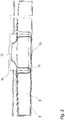
- Fig. 5 illustrates a cross section a wind turbine tower 2 comprising a first embodiment of a rail 12, as seen from the top.
- the rail 12 is welded directly to the inside surface of the foundation section 14, but in another embodiment the rail 12 could also be bolted to the foundation section 14 or if the foundation does not comprise a foundation section 14, the rail 12 could be mounted on the bottom of the tower 2 immediately above the foundation 6. No matter the design or type of the tower 2 or the foundation 6 it is an object of the invention to establish a connection between all power and/or signal conducting cables 16, 18, 19 to an electrically earth potential in form of the rail 12 in one defined place within the wind turbine 1.
- the down conductor of the lightning protection system is defined as the entire tower construction (a natural down conductor), practically one large extensive metal framework.
- all cable screens or concentric earth wire in all high voltage cables 16 entering the tower 2 will be connected to the rail 12 in form of a main earth bonding bar 12, directly when entering the tower 2. This could be done by stripping a part of the high voltage cable 16 to lay open the screen. The screen could then by means of copper springs, nets and/or braids be connected to the rail 12 by forming a loop from the screen to the rail 12.
- Fibre optic cables 19 with metallic cable screens will also be connected directly to the main earth bonding bar 12, directly at the entering point.
- All conventional copper signal-, control- or communication cables 18 will be entered into the turbine 1 via overvoltage arresters placed in a termination box/equipotential box 17 installed near or directly on the main earth bonding bar 12.
- This box 17 contains overvoltage arresters according to number and type of cables 18 planned to enter the turbine 1.
- the number and the type of signal- or communication cables 18 entering each turbine 1 is always site specific, whereas the number and type of the overvoltage arresters also are specific for each turbine 1.
- the cable screens of the signal-, control - or communication cables 18 will be connected to the earthing terminals in the equipotential box 17, on both incoming and outgoing cables 18.
- Fibre optic cables without metallic cable screens are allowed to enter the turbine 1 without connecting the cable to the main earth bonding bar 12.
- Fig. 6 illustrates a cross section a wind turbine tower 2 comprising a second embodiment of a rail 12, as seen from the top.
- the 12 all the power and/or signal conducting cables 16, 18, 19 and cables from all earthing systems 7, 8, 9, 11 are all connected in one defined area via the rail 12 at the bottom of the tower 2.
- the rail 12 is then further connected to the tower 2 by means of a earth cable 20 which thereby further establishes a direct or indirect current conducting connection between the earthing system 7 and all connected metal parts of the wind turbine 1.
- Fig. 7 illustrates a cross section a wind turbine tower 2 comprising a rail 12, as seen from the front.
- SPE single point of entry
- the power and/or signal conducting cables 16, 18, 19 and cables from all earthing systems 7, 8, 9, 11 can be connected to the rail 12 in a number of different ways.
- a well known way is to provide the end of the cable with a cable lock and then connect it to the rail 12 by means of a bolt through the hole in the cable lock.
- the equipotential box 17 is placed beside the rail 12 but in another embodiment of the invention the box 17 would be placed directly on the rail 12.
- the rail 12 is in this embodiment connected to an electric system in form of a low or high voltage power system (according to IEC a low voltage system is all systems bellow 1000 volts and high voltage systems are all systems above 1000 volts).
- the rail is further connected to a control system in form of a SCADA (Supervisory Control And Data Acquisition) system.
- SCADA Supervisory Control And Data Acquisition
- the SCADA system is a large-scale, distributed measurement (and control) system often used in wind turbine parks 10, but also in relation with individually sited wind turbines 1.
- the rail 12 is connected to a safety system in form of a lightning protection system, which ensures that if a lightening strikes the wind turbine, the power is lead into the ground without damaging the wind turbine 1.
- Fig 8 illustrates a schematic view of the cabling in a wind turbine park 10, as seen from the top
- the substation 21 could comprise transformers, equipment to facilitate the host control functions of the SCADA system, accommodation, storage room and other facilities.
- the earth interconnection wire 11 serves both as a part of the earthing system 7 but also as a part of a lightning protection of the high voltage cables 16 running between each wind turbine 1 and between wind turbines 1 and sub station 21.
- each of the towers 2 a main earth bonding bar 12 is installed. All earthing connections 7, 8, 9, 11 are connected directly to this rail 12 in all the wind turbines 1. Additionally equipotential connections to all cables, or cable screens, are made immediately after the cables have entered the wind turbine 1.
- each wind turbine 1 and substation 21 is connected by the concentric cable screen or earth wire which forms part of the high voltage cable 16 connecting the wind turbines 1 and sub station 21.
- the earthing system 7 are regarded as a multi-earthed HV (High Voltage) neutral conductor system.
- a bare stranded cupper conductor 9 is installed which hereby forms an earth interconnection wire 11.
- the earth interconnection wire 11 is buried along with, but above the high voltage cables 16, to make the wires 11 act as lightening protection of the high voltage cables 16 through their entire path in the ground. But in some parts of the world there can be local rules or regulations dictating another placement of the earth interconnection wire 11 such as bellow or beside the high voltage cables 16.
- the communication cables 18 containing metallic wires, screens, armour, tapes etc. are preferably placed in separate cable trenches, an minimum of 1 meter away from the cable trench containing high voltage cables 16, when running in parallel direction.
- the distance to the low voltage cable, in the cross point is preferably no less than 0.3 meters.
- Fig. 9 illustrates a cross section of an embodiment of a pier foundation 24 comprising an earthing system 7, as seen from the front.
- the pier foundation 24 comprise two metal support structures 23 in the form of an inner and an outer corrugated pipe shell.
- the distance between the two structures 23 are maintained by means of a number of threaded rods 25 made from metal such as steel, hereby also forming an electrical connection between the two support structures 23.
- a pier foundation 24 is a foundation type that is usually formed by digging a large hole in the ground and placing two concentric metal support structures 23 in the hole. Basically the space between the two structures is provided with a number of anchor bolts 26 where after the space is filled with concrete 28. The anchor bolts 26 are used for attaching the tower 2 to the foundation 6.
- Electric conducting means 9 e.g. in the form of a bare stranded cupper wire is in this embodiment connected to one or more of the threaded bolts 25 and embedded through the concrete 28 and up above the upper surface of the foundation for connection to the rail 12.
- the structures 23 could be galvanized but if they are galvanized, the Zink surface layer will work as a sacrificial anode for the electric conducting means 9. Therefore the Zink layer will disappear over a relatively short time.
- the entire outer side of the whole foundation 6 is therefore covered by concrete or slurry 28 (same characteristic) making the bare steel surface of the support structures 23 inactive, corrosion wise.
- the inside of the inner pipe shell of the foundation 24 is filled with concrete 28 but in another embodiment only an annular trench could be dug with an inner diameter smaller then the inner diameter of the inner pipe shell, leaving a cavity which could be filled with concrete 28, slurry or dirt.
- the structures 23 are placed on a number of spacers 27 e.g. formed as prefabricated concrete bricks, hereby allowing concrete or slurry 28 to flow in under the structures 23 during the making of the foundation 24.
- Fig. 10 illustrates an embodiment of a pier foundation 24 comprising an earthing system 7, as seen from the top.
- the electric conducting means 9 are formed as one single wire partially embedded in the concrete 28 and connected to all four threaded rods near the top of the foundation 24 by means of connection terminals 29 or rebar clamps. The two free ends of the electric conducting means 9 are guided through the concrete 28 and up into the single point of entry 22 for connection to the rail 12.
- the pier foundation 24 is further provided with annular metal reinforcement 30 between the two annular metal support structures 23.
- the electric conducting means 9 could be connected directly to the metal support structures 23, to the annular reinforcement 30 or other or the electric conducting means 9 could be connected to another number of anchor bolts 26 such as one, two, three, six or more.
Applications Claiming Priority (3)
| Application Number | Priority Date | Filing Date | Title |
|---|---|---|---|
| DKPA200600718 | 2006-05-24 | ||
| DKPA200601218 | 2006-09-21 | ||
| PCT/DK2006/000568 WO2007134599A1 (en) | 2006-05-24 | 2006-10-09 | An earthing system for a wind turbine connected to a utility grid and for a wind turbine park |
Publications (2)
| Publication Number | Publication Date |
|---|---|
| EP2021627A1 EP2021627A1 (en) | 2009-02-11 |
| EP2021627B1 true EP2021627B1 (en) | 2018-01-03 |
Family
ID=37686116
Family Applications (1)
| Application Number | Title | Priority Date | Filing Date |
|---|---|---|---|
| EP06791456.4A Active EP2021627B1 (en) | 2006-05-24 | 2006-10-09 | An earthing system for a wind turbine connected to a utility grid and for a wind turbine park |
Country Status (5)
| Country | Link |
|---|---|
| US (1) | US8383933B2 (es) |
| EP (1) | EP2021627B1 (es) |
| CN (1) | CN101473136B (es) |
| ES (1) | ES2657089T3 (es) |
| WO (1) | WO2007134599A1 (es) |
Families Citing this family (17)
| Publication number | Priority date | Publication date | Assignee | Title |
|---|---|---|---|---|
| US9768603B2 (en) * | 2009-08-24 | 2017-09-19 | Siemens Aktiengesellschaft | Lightning protection system |
| DE102009050378B4 (de) * | 2009-10-22 | 2018-12-20 | Phoenix Contact Gmbh & Co. Kg | Vorrichtung und Verfahren zur Blitzstrommessung |
| EP2378850B1 (en) * | 2010-04-16 | 2013-05-29 | Siemens Aktiengesellschaft | Tower with EMC protection system |
| US8727723B2 (en) | 2010-07-23 | 2014-05-20 | Erico International Corporation | Receptor for wind turbine blade lightning protection |
| ES2771049T3 (es) * | 2010-08-20 | 2020-07-06 | Siemens Gamesa Renewable Energy As | Sistema de medición para un conductor de bajada de una pala de turbina eólica |
| CN101958466B (zh) * | 2010-09-21 | 2012-06-20 | 国电联合动力技术有限公司 | 一种圆筒型基础环接地装置 |
| WO2012081840A2 (ko) * | 2010-12-13 | 2012-06-21 | 주식회사 한국서지연구소 | 지하 관정 및 금속제 함체를 구비한 제어반과 원격 제어반을 포함한 설비의 스마트 접지 본딩공법 |
| DE102011003208B4 (de) * | 2011-01-26 | 2016-05-25 | Senvion Gmbh | Turm einer Windenergieanlage mit Stromleitmitteln |
| US9617704B2 (en) | 2014-05-27 | 2017-04-11 | One Energy Enterprises Llc | Reinforcement assemblies, fixtures, and methods |
| US20170184070A1 (en) * | 2015-12-24 | 2017-06-29 | Leon Clyde Blasingame | Tidal flow power generation System and Method |
| CN106640540A (zh) * | 2016-10-08 | 2017-05-10 | 霍尔果斯新国金新能源科技有限公司 | 用于风力发电机的混凝土塔筒 |
| PT3312416T (pt) * | 2016-10-24 | 2022-07-26 | Nordex Energy Spain Sau | Fundação para turbina eólica e método para construção da mesma |
| DE102017007371A1 (de) * | 2017-08-07 | 2019-02-07 | Senvion Gmbh | Rotorblatt einer Windenergieanlage und Verfahren zum Nachrüsten einer Blitzschutzeinrichtung eines Rotorblatts |
| BR112021004388A2 (pt) * | 2018-09-24 | 2021-07-20 | Polytech A/S | sistema de conexão de condutor para-raios, sistema de proteção contra relâmpagos de turbina eólica e método para dispor um sistema de conexão de condutor para-raios |
| EP3722599B1 (en) * | 2019-04-09 | 2022-09-28 | Siemens Gamesa Renewable Energy A/S | Electromagnetic grounding arrangement |
| NO347187B1 (no) * | 2019-11-22 | 2023-06-26 | Oeglaend System As | Jordingsanordning for en betongkonstruksjon og system omfattende jordingsanordningen |
| JP7421181B2 (ja) * | 2020-10-09 | 2024-01-24 | 株式会社落雷抑制システムズ | 落雷抑制型風力発電設備 |
Family Cites Families (9)
| Publication number | Priority date | Publication date | Assignee | Title |
|---|---|---|---|---|
| FR2611990B1 (fr) * | 1987-03-06 | 1989-10-20 | Thomson Csf | Dispositif de protection contre la foudre d'une antenne radar mobile |
| US6177630B1 (en) * | 1998-10-15 | 2001-01-23 | Qwest Communications International Inc. | Equipment installation concrete pad having integrated equipotential grounding plane and method for installing equipment using same |
| JP2000265938A (ja) * | 1999-03-17 | 2000-09-26 | Hitachi Ltd | 風力発電の雷保護システム |
| DK173607B1 (da) * | 1999-06-21 | 2001-04-30 | Lm Glasfiber As | Vindmøllevinge med system til afisning af lynbeskyttelse |
| US6455777B1 (en) * | 2000-03-20 | 2002-09-24 | Dekko Engineering, Inc. | Using bare stranded copper wire for grounding to conduit or steel channel |
| JP2002320319A (ja) | 2001-04-18 | 2002-10-31 | Hokuriku Electric Power Co Inc:The | 雷被害防護方法 |
| JP2004225660A (ja) * | 2003-01-27 | 2004-08-12 | Tohoku Electric Power Co Inc | 耐雷風力発電設備 |
| JP4355793B2 (ja) * | 2004-04-08 | 2009-11-04 | 学校法人金沢工業大学 | 風力発電装置 |
| US20050230980A1 (en) * | 2004-04-15 | 2005-10-20 | Andre Brunet | Wind turbine mounted on power transmission tower |
-
2006
- 2006-10-09 WO PCT/DK2006/000568 patent/WO2007134599A1/en active Application Filing
- 2006-10-09 CN CN2006800550857A patent/CN101473136B/zh active Active
- 2006-10-09 ES ES06791456.4T patent/ES2657089T3/es active Active
- 2006-10-09 US US12/302,247 patent/US8383933B2/en active Active
- 2006-10-09 EP EP06791456.4A patent/EP2021627B1/en active Active
Also Published As
| Publication number | Publication date |
|---|---|
| CN101473136A (zh) | 2009-07-01 |
| WO2007134599A9 (en) | 2009-02-19 |
| ES2657089T3 (es) | 2018-03-01 |
| EP2021627A1 (en) | 2009-02-11 |
| US8383933B2 (en) | 2013-02-26 |
| US20090272557A1 (en) | 2009-11-05 |
| WO2007134599A1 (en) | 2007-11-29 |
| CN101473136B (zh) | 2012-09-19 |
Similar Documents
| Publication | Publication Date | Title |
|---|---|---|
| EP2021627B1 (en) | An earthing system for a wind turbine connected to a utility grid and for a wind turbine park | |
| EP2471153B1 (en) | Lightning protection system | |
| AU752241B2 (en) | Transmission conduit and method of installation of same | |
| Hoerauf | Considerations in wind farm grounding designs | |
| KR101321090B1 (ko) | 핵심보호체 보호를 위한 낙뢰 방지기 | |
| JP2004225660A (ja) | 耐雷風力発電設備 | |
| CN105507646B (zh) | 通信基站 | |
| CN105375126A (zh) | 通信基站的防雷接地系统 | |
| CN210041325U (zh) | 一种平衡电网对地电流的装置 | |
| CN2552215Y (zh) | 用于通信局站防直击雷的独立式避雷针装置 | |
| JP7173894B2 (ja) | 避雷接地装置及び避雷接地方法 | |
| CN113839311B (zh) | 一种多功能智能杆防雷方法 | |
| JP2598633B2 (ja) | 原子炉建屋およびその接地方法 | |
| CN216355298U (zh) | 一种多功能智能杆防雷系统 | |
| KR200253293Y1 (ko) | 수개의 구멍이 뚫린 접지용 동파이프 | |
| CN210404074U (zh) | 一种导电混凝土防水防雷击接地网 | |
| KR100361201B1 (ko) | 접지극을 구비한 내·외장형 콘크리트 전주 | |
| Foumani et al. | Improvement of grounding system in wind farms regarding the permissible potentials | |
| Prada‐Gil et al. | Offshore Wind Power Plants (OWPPS) | |
| CN108599084B (zh) | 一种潮流能机组的雷电防护系统及包括其的潮流能机组 | |
| JP4919793B2 (ja) | 接地装置、接地設備及び接地装置の製造方法 | |
| KR100751830B1 (ko) | 전위 상승 억제 기능을 갖는 접지선 | |
| Luis et al. | OFFSHORE WIND POWER PLANTS (OWPPS) | |
| CN115441215A (zh) | 一种接地网系统 | |
| KR20050065023A (ko) | 콘크리트 전주의 내장 접지선 고정 클립 |
Legal Events
| Date | Code | Title | Description |
|---|---|---|---|
| PUAI | Public reference made under article 153(3) epc to a published international application that has entered the european phase |
Free format text: ORIGINAL CODE: 0009012 |
|
| 17P | Request for examination filed |
Effective date: 20081210 |
|
| AK | Designated contracting states |
Kind code of ref document: A1 Designated state(s): AT BE BG CH CY CZ DE DK EE ES FI FR GB GR HU IE IS IT LI LT LU LV MC NL PL PT RO SE SI SK TR |
|
| AX | Request for extension of the european patent |
Extension state: AL BA HR MK RS |
|
| RIN1 | Information on inventor provided before grant (corrected) |
Inventor name: BERTELSEN, KIM Inventor name: MOGENSEN, NIELS, BIRCH |
|
| RAP1 | Party data changed (applicant data changed or rights of an application transferred) |
Owner name: VESTAS WIND SYSTEMS A/S |
|
| DAX | Request for extension of the european patent (deleted) | ||
| RAP1 | Party data changed (applicant data changed or rights of an application transferred) |
Owner name: VESTAS WIND SYSTEMS A/S |
|
| 17Q | First examination report despatched |
Effective date: 20160309 |
|
| REG | Reference to a national code |
Ref country code: DE Ref legal event code: R079 Ref document number: 602006054478 Country of ref document: DE Free format text: PREVIOUS MAIN CLASS: F03D0009000000 Ipc: F03D0013200000 |
|
| GRAP | Despatch of communication of intention to grant a patent |
Free format text: ORIGINAL CODE: EPIDOSNIGR1 |
|
| RIC1 | Information provided on ipc code assigned before grant |
Ipc: F03D 13/20 20160101AFI20170320BHEP Ipc: F03D 9/25 20160101ALI20170320BHEP Ipc: F03D 80/00 20160101ALI20170320BHEP Ipc: H02G 13/00 20060101ALI20170320BHEP Ipc: F03D 80/30 20160101ALI20170320BHEP |
|
| INTG | Intention to grant announced |
Effective date: 20170405 |
|
| GRAS | Grant fee paid |
Free format text: ORIGINAL CODE: EPIDOSNIGR3 |
|
| GRAA | (expected) grant |
Free format text: ORIGINAL CODE: 0009210 |
|
| AK | Designated contracting states |
Kind code of ref document: B1 Designated state(s): AT BE BG CH CY CZ DE DK EE ES FI FR GB GR HU IE IS IT LI LT LU LV MC NL PL PT RO SE SI SK TR |
|
| REG | Reference to a national code |
Ref country code: GB Ref legal event code: FG4D |
|
| REG | Reference to a national code |
Ref country code: CH Ref legal event code: EP Ref country code: AT Ref legal event code: REF Ref document number: 960538 Country of ref document: AT Kind code of ref document: T Effective date: 20180115 |
|
| REG | Reference to a national code |
Ref country code: IE Ref legal event code: FG4D |
|
| REG | Reference to a national code |
Ref country code: DE Ref legal event code: R096 Ref document number: 602006054478 Country of ref document: DE |
|
| REG | Reference to a national code |
Ref country code: ES Ref legal event code: FG2A Ref document number: 2657089 Country of ref document: ES Kind code of ref document: T3 Effective date: 20180301 |
|
| REG | Reference to a national code |
Ref country code: NL Ref legal event code: MP Effective date: 20180103 |
|
| REG | Reference to a national code |
Ref country code: LT Ref legal event code: MG4D |
|
| REG | Reference to a national code |
Ref country code: AT Ref legal event code: MK05 Ref document number: 960538 Country of ref document: AT Kind code of ref document: T Effective date: 20180103 |
|
| PG25 | Lapsed in a contracting state [announced via postgrant information from national office to epo] |
Ref country code: NL Free format text: LAPSE BECAUSE OF FAILURE TO SUBMIT A TRANSLATION OF THE DESCRIPTION OR TO PAY THE FEE WITHIN THE PRESCRIBED TIME-LIMIT Effective date: 20180103 |
|
| PG25 | Lapsed in a contracting state [announced via postgrant information from national office to epo] |
Ref country code: FI Free format text: LAPSE BECAUSE OF FAILURE TO SUBMIT A TRANSLATION OF THE DESCRIPTION OR TO PAY THE FEE WITHIN THE PRESCRIBED TIME-LIMIT Effective date: 20180103 Ref country code: CY Free format text: LAPSE BECAUSE OF FAILURE TO SUBMIT A TRANSLATION OF THE DESCRIPTION OR TO PAY THE FEE WITHIN THE PRESCRIBED TIME-LIMIT Effective date: 20180103 Ref country code: LT Free format text: LAPSE BECAUSE OF FAILURE TO SUBMIT A TRANSLATION OF THE DESCRIPTION OR TO PAY THE FEE WITHIN THE PRESCRIBED TIME-LIMIT Effective date: 20180103 |
|
| PG25 | Lapsed in a contracting state [announced via postgrant information from national office to epo] |
Ref country code: BG Free format text: LAPSE BECAUSE OF FAILURE TO SUBMIT A TRANSLATION OF THE DESCRIPTION OR TO PAY THE FEE WITHIN THE PRESCRIBED TIME-LIMIT Effective date: 20180403 Ref country code: LV Free format text: LAPSE BECAUSE OF FAILURE TO SUBMIT A TRANSLATION OF THE DESCRIPTION OR TO PAY THE FEE WITHIN THE PRESCRIBED TIME-LIMIT Effective date: 20180103 Ref country code: SE Free format text: LAPSE BECAUSE OF FAILURE TO SUBMIT A TRANSLATION OF THE DESCRIPTION OR TO PAY THE FEE WITHIN THE PRESCRIBED TIME-LIMIT Effective date: 20180103 Ref country code: IS Free format text: LAPSE BECAUSE OF FAILURE TO SUBMIT A TRANSLATION OF THE DESCRIPTION OR TO PAY THE FEE WITHIN THE PRESCRIBED TIME-LIMIT Effective date: 20180503 Ref country code: PL Free format text: LAPSE BECAUSE OF FAILURE TO SUBMIT A TRANSLATION OF THE DESCRIPTION OR TO PAY THE FEE WITHIN THE PRESCRIBED TIME-LIMIT Effective date: 20180103 Ref country code: AT Free format text: LAPSE BECAUSE OF FAILURE TO SUBMIT A TRANSLATION OF THE DESCRIPTION OR TO PAY THE FEE WITHIN THE PRESCRIBED TIME-LIMIT Effective date: 20180103 Ref country code: GR Free format text: LAPSE BECAUSE OF FAILURE TO SUBMIT A TRANSLATION OF THE DESCRIPTION OR TO PAY THE FEE WITHIN THE PRESCRIBED TIME-LIMIT Effective date: 20180404 |
|
| REG | Reference to a national code |
Ref country code: DE Ref legal event code: R097 Ref document number: 602006054478 Country of ref document: DE |
|
| REG | Reference to a national code |
Ref country code: FR Ref legal event code: PLFP Year of fee payment: 13 |
|
| PG25 | Lapsed in a contracting state [announced via postgrant information from national office to epo] |
Ref country code: IT Free format text: LAPSE BECAUSE OF FAILURE TO SUBMIT A TRANSLATION OF THE DESCRIPTION OR TO PAY THE FEE WITHIN THE PRESCRIBED TIME-LIMIT Effective date: 20180103 Ref country code: RO Free format text: LAPSE BECAUSE OF FAILURE TO SUBMIT A TRANSLATION OF THE DESCRIPTION OR TO PAY THE FEE WITHIN THE PRESCRIBED TIME-LIMIT Effective date: 20180103 Ref country code: EE Free format text: LAPSE BECAUSE OF FAILURE TO SUBMIT A TRANSLATION OF THE DESCRIPTION OR TO PAY THE FEE WITHIN THE PRESCRIBED TIME-LIMIT Effective date: 20180103 |
|
| PLBE | No opposition filed within time limit |
Free format text: ORIGINAL CODE: 0009261 |
|
| STAA | Information on the status of an ep patent application or granted ep patent |
Free format text: STATUS: NO OPPOSITION FILED WITHIN TIME LIMIT |
|
| PG25 | Lapsed in a contracting state [announced via postgrant information from national office to epo] |
Ref country code: DK Free format text: LAPSE BECAUSE OF FAILURE TO SUBMIT A TRANSLATION OF THE DESCRIPTION OR TO PAY THE FEE WITHIN THE PRESCRIBED TIME-LIMIT Effective date: 20180103 Ref country code: SK Free format text: LAPSE BECAUSE OF FAILURE TO SUBMIT A TRANSLATION OF THE DESCRIPTION OR TO PAY THE FEE WITHIN THE PRESCRIBED TIME-LIMIT Effective date: 20180103 Ref country code: CZ Free format text: LAPSE BECAUSE OF FAILURE TO SUBMIT A TRANSLATION OF THE DESCRIPTION OR TO PAY THE FEE WITHIN THE PRESCRIBED TIME-LIMIT Effective date: 20180103 |
|
| 26N | No opposition filed |
Effective date: 20181005 |
|
| PG25 | Lapsed in a contracting state [announced via postgrant information from national office to epo] |
Ref country code: SI Free format text: LAPSE BECAUSE OF FAILURE TO SUBMIT A TRANSLATION OF THE DESCRIPTION OR TO PAY THE FEE WITHIN THE PRESCRIBED TIME-LIMIT Effective date: 20180103 |
|
| REG | Reference to a national code |
Ref country code: CH Ref legal event code: PL |
|
| REG | Reference to a national code |
Ref country code: BE Ref legal event code: MM Effective date: 20181031 |
|
| PG25 | Lapsed in a contracting state [announced via postgrant information from national office to epo] |
Ref country code: LU Free format text: LAPSE BECAUSE OF NON-PAYMENT OF DUE FEES Effective date: 20181009 Ref country code: MC Free format text: LAPSE BECAUSE OF FAILURE TO SUBMIT A TRANSLATION OF THE DESCRIPTION OR TO PAY THE FEE WITHIN THE PRESCRIBED TIME-LIMIT Effective date: 20180103 |
|
| REG | Reference to a national code |
Ref country code: IE Ref legal event code: MM4A |
|
| PG25 | Lapsed in a contracting state [announced via postgrant information from national office to epo] |
Ref country code: LI Free format text: LAPSE BECAUSE OF NON-PAYMENT OF DUE FEES Effective date: 20181031 Ref country code: CH Free format text: LAPSE BECAUSE OF NON-PAYMENT OF DUE FEES Effective date: 20181031 Ref country code: BE Free format text: LAPSE BECAUSE OF NON-PAYMENT OF DUE FEES Effective date: 20181031 |
|
| PG25 | Lapsed in a contracting state [announced via postgrant information from national office to epo] |
Ref country code: IE Free format text: LAPSE BECAUSE OF NON-PAYMENT OF DUE FEES Effective date: 20181009 |
|
| PG25 | Lapsed in a contracting state [announced via postgrant information from national office to epo] |
Ref country code: TR Free format text: LAPSE BECAUSE OF FAILURE TO SUBMIT A TRANSLATION OF THE DESCRIPTION OR TO PAY THE FEE WITHIN THE PRESCRIBED TIME-LIMIT Effective date: 20180103 |
|
| PG25 | Lapsed in a contracting state [announced via postgrant information from national office to epo] |
Ref country code: PT Free format text: LAPSE BECAUSE OF FAILURE TO SUBMIT A TRANSLATION OF THE DESCRIPTION OR TO PAY THE FEE WITHIN THE PRESCRIBED TIME-LIMIT Effective date: 20180103 |
|
| PG25 | Lapsed in a contracting state [announced via postgrant information from national office to epo] |
Ref country code: HU Free format text: LAPSE BECAUSE OF FAILURE TO SUBMIT A TRANSLATION OF THE DESCRIPTION OR TO PAY THE FEE WITHIN THE PRESCRIBED TIME-LIMIT; INVALID AB INITIO Effective date: 20061009 |
|
| P01 | Opt-out of the competence of the unified patent court (upc) registered |
Effective date: 20230521 |
|
| PGFP | Annual fee paid to national office [announced via postgrant information from national office to epo] |
Ref country code: GB Payment date: 20231024 Year of fee payment: 18 |
|
| PGFP | Annual fee paid to national office [announced via postgrant information from national office to epo] |
Ref country code: ES Payment date: 20231110 Year of fee payment: 18 |
|
| PGFP | Annual fee paid to national office [announced via postgrant information from national office to epo] |
Ref country code: FR Payment date: 20231026 Year of fee payment: 18 Ref country code: DE Payment date: 20231027 Year of fee payment: 18 |