EP2021137B1 - Machine for assembling metal section bars of frames - Google Patents
Machine for assembling metal section bars of frames Download PDFInfo
- Publication number
- EP2021137B1 EP2021137B1 EP07734534A EP07734534A EP2021137B1 EP 2021137 B1 EP2021137 B1 EP 2021137B1 EP 07734534 A EP07734534 A EP 07734534A EP 07734534 A EP07734534 A EP 07734534A EP 2021137 B1 EP2021137 B1 EP 2021137B1
- Authority
- EP
- European Patent Office
- Prior art keywords
- section bars
- machine according
- operating position
- caulking
- assembly unit
- Prior art date
- Legal status (The legal status is an assumption and is not a legal conclusion. Google has not performed a legal analysis and makes no representation as to the accuracy of the status listed.)
- Not-in-force
Links
- 229910052751 metal Inorganic materials 0.000 title claims abstract description 28
- 239000002184 metal Substances 0.000 title claims abstract description 28
- 238000003754 machining Methods 0.000 claims abstract description 11
- 238000004026 adhesive bonding Methods 0.000 claims description 10
- 238000005553 drilling Methods 0.000 claims description 9
- 238000005520 cutting process Methods 0.000 claims description 8
- 238000003801 milling Methods 0.000 claims description 8
- 230000008878 coupling Effects 0.000 claims 2
- 238000010168 coupling process Methods 0.000 claims 2
- 238000005859 coupling reaction Methods 0.000 claims 2
- 238000004519 manufacturing process Methods 0.000 description 4
- 239000004411 aluminium Substances 0.000 description 3
- 229910052782 aluminium Inorganic materials 0.000 description 3
- XAGFODPZIPBFFR-UHFFFAOYSA-N aluminium Chemical compound [Al] XAGFODPZIPBFFR-UHFFFAOYSA-N 0.000 description 3
- 239000003292 glue Substances 0.000 description 3
- 238000004140 cleaning Methods 0.000 description 2
- 238000003780 insertion Methods 0.000 description 2
- 230000037431 insertion Effects 0.000 description 2
- 238000003892 spreading Methods 0.000 description 2
- 238000011144 upstream manufacturing Methods 0.000 description 2
- 238000010276 construction Methods 0.000 description 1
- 230000008602 contraction Effects 0.000 description 1
- 230000010339 dilation Effects 0.000 description 1
- 238000007599 discharging Methods 0.000 description 1
- 230000000284 resting effect Effects 0.000 description 1
Images




Classifications
-
- B—PERFORMING OPERATIONS; TRANSPORTING
- B21—MECHANICAL METAL-WORKING WITHOUT ESSENTIALLY REMOVING MATERIAL; PUNCHING METAL
- B21D—WORKING OR PROCESSING OF SHEET METAL OR METAL TUBES, RODS OR PROFILES WITHOUT ESSENTIALLY REMOVING MATERIAL; PUNCHING METAL
- B21D53/00—Making other particular articles
- B21D53/74—Making other particular articles frames for openings, e.g. for windows, doors, handbags
- B21D53/745—Joining mitred profiles comprising punching the profiles on a corner-angle connecting piece
-
- B—PERFORMING OPERATIONS; TRANSPORTING
- B23—MACHINE TOOLS; METAL-WORKING NOT OTHERWISE PROVIDED FOR
- B23P—METAL-WORKING NOT OTHERWISE PROVIDED FOR; COMBINED OPERATIONS; UNIVERSAL MACHINE TOOLS
- B23P19/00—Machines for simply fitting together or separating metal parts or objects, or metal and non-metal parts, whether or not involving some deformation; Tools or devices therefor so far as not provided for in other classes
-
- Y—GENERAL TAGGING OF NEW TECHNOLOGICAL DEVELOPMENTS; GENERAL TAGGING OF CROSS-SECTIONAL TECHNOLOGIES SPANNING OVER SEVERAL SECTIONS OF THE IPC; TECHNICAL SUBJECTS COVERED BY FORMER USPC CROSS-REFERENCE ART COLLECTIONS [XRACs] AND DIGESTS
- Y10—TECHNICAL SUBJECTS COVERED BY FORMER USPC
- Y10T—TECHNICAL SUBJECTS COVERED BY FORMER US CLASSIFICATION
- Y10T29/00—Metal working
- Y10T29/51—Plural diverse manufacturing apparatus including means for metal shaping or assembling
- Y10T29/5124—Plural diverse manufacturing apparatus including means for metal shaping or assembling with means to feed work intermittently from one tool station to another
Definitions
- the invention relates to a machine tool according the preamble of claim 1 arranged for assembling metal section bars of casings.
- the invention relates to a caulking machine arranged for caulking metal section bars for making casings of frames, such as, for example, windows, french windows, doors, shutters, and the like.
- the caulking machines used in the door and window industry, or corner assembling machines, are arranged for fixing the corners of the casings.
- Each corner of a casing is defined by a pair of metal section bars, for example extruded aluminium sections, that are appropriately placed near one another and previously connected at respective end portions by connecting elements, or corner joints.
- Each corner joint which for example also may be an extruded aluminium section, comprises a pair of arms each provided with a fixing seat, and arranged in such a way as to make a substantially L-shaped structure.
- Each arm is arranged for being inserted into a respective housing obtained in the aforesaid end portions of the section bars to be joined.
- the deformed portions each engage the respective fixing seat, achieving mechanical locking between the section bars and the corner joint interposed therebetween.
- a glue can be injected into holes that have previously been made in the section bars, which glue is arranged for stably fixing the section bars.
- Caulking machines are known that are arranged for fixing the corners of a casing, comprising a box framework closed below by a base and by a supporting plate above.
- a supporting element which is substantially L-shaped, arranged for supporting, in use, a pair of section bars to be caulked, previously connected by a corner joint by an operator.
- These machines further comprise a caulking head supported by the supporting plate and arranged for caulking and gluing, each time, a pair of section bars, until the desired casing is made.
- the caulking head is provided with a caulking clamp, positioned near the vertex of the supporting element, comprising a pair of jaws, each supporting a metal cutter arranged for plastically deforming a respective portion of metal section bar facing the latter.
- the operator removes from the caulking machine the L-shaped structure that has just been fixed, inserts into one of the free ends of the latter a second corner joint, and associates therewith a third section bar, obtaining a U-shaped structure.
- the operator manually positions the U-shaped structure thus obtained on the supporting element, and manually drives the caulking head that fixes the third section bar to the L-shaped structure, making a second corner of the casing.
- the operator removes from the caulking machine the thus fixed U-shaped structure, inserts a third and a fourth corner joint into a fourth section bar and associates the fourth section bar with the free ends of the U-shaped structure, obtaining a closed, for example rectangular, structure.
- the operator manually positions the closed structure thereby obtained on the supporting element, and manually drives the caulking head that fixes the fourth section bar to one of the free ends of the U-shaped structure so as to make a third corner of the casing.
- the operator removes the partially fixed closed structure, rotates the partially fixed closed structure and repositions the partially fixed closed structure on the caulking head that fixes a fourth corner of the casing.
- caulking forces are discharged by the caulking clamps onto the supporting plate, caulking clamps being associated with the latter by a threaded connection.
- a drawback of known caulking machines consists of the low productivity thereof.
- a further drawback consists of the need to provide an operator, with a consequent increase in production costs, to perform manually the tasks of assembling and positioning on the caulking machine the section bars to be fixed.
- the operator may commit centring errors and compromise the subsequent caulking of the section bars, or injure himself by coming into contact accidentally with the free ends of the section bars to be joined.
- manually moving the partially assembled section bars in particular for section bars of large dimensions, may be particularly heavy for the operator.
- a still further drawback relates to the operations that are necessary for reconfiguring the aforesaid caulking machines following a change in the size of the section bars to be caulked.
- EP-A-0925868 discloses an apparatus in accordance with the preamble of claim 1 for the production of window frames made of profile sections comprising an assembly unit arranged for supporting and assembling the profile sections.
- the assembly unit is in connection with an insertion device which is provided upstream the assembly unit and is arranged so as to convey the profile sections to an insertion position on the assembly unit.
- JP 59 088230 A discloses an assembly base for the construction of an assembly system employing an assembly robot having three rectangular axes.
- the assembly base comprises a jig station movable from an assembly position to a processing position.
- JP 60 135149 A discloses an apparatus for assembling a box structure comprising an assembly station for assembling the box structure and a processing station on which the assembled parts of the box structure are joined together.
- US-A-5,379,835 discloses an apparatus for manufacturing rectangular frames on which frame elements are assembled and joined together on a turntable.
- An object of the invention is to improve the machine tools arranged for assembling metal section bars of casings. Another object is to improve machine tools arranged for caulking metal section bars for making casings.
- a further object is to make machine tools that enable productivity to be increased with respect to known caulking machines.
- a still further object is to obtain machine tools that enable the section bars to be assembled rapidly.
- Still another object is to make machine tools that enable rapid and precise centring of the section bars to be assembled.
- Another still further object is to make machine tools that are easily and rapidly reconfigurable following a change in the size of the section bars to be caulked.
- Still another object is to obtain caulking machines provided with a device for discharging the caulking forces that is alternative to known devices.
- a machine tool for assembling metal section bars of casings comprising an assembly unit arranged for supporting and assembling said metal section bars, said assembly unit being movable between a first operating position in which said metal section bars are positionable on said assembly unit and a second operating position in which said metal section bars can be subjected to a desired machining, characterized in that said assembly unit is rotatable around a rotation axis between said first operating position and said second operating position, said assembly unit comprising supporting frame means arranged for supporting said metal section bars and said casings, said supporting frame means comprises a first frame and a second frame positioned on sides opposite with respect to said rotation axis.
- This machine tool may comprise at said first operating position and at the aforesaid second operating position respectively a first manipulating unit and a second manipulating unit, each of which is provided with an anthropomorphic robot.
- the anthropomorphic robot of the first manipulating unit is arranged for loading said metal section bars on said assembly unit
- the anthropomorphic robot of the second manipulating unit can be provided with caulking means arranged for caulking and gluing said metal section bars, or with a drilling unit arranged for drilling said section bars, or with a broaching machine arranged for inserting broaches into said section bars, or with a screwing head.
- FIG. 1 there is illustrated a system 1 used in the door and window industry for machining and assembling casings 2 of frames ( Figure 10 ) such as, for example, windows, french windows, doors, shutters, and the like.
- the system 1 comprises a loading magazine 3 arranged for loading onto the caulking machine 1 section bars 4 ( Figure 5 ) that have not yet been machined, for example extruded aluminium sections, arranged, once they have been finished, for being assembled to make a casing 2.
- the loading magazine 3 is provided with gripping means, which are not shown, which are arranged for firmly gripping the section bars 4 and for conveying the latter to a cutting/milling centre 5 positioned downstream of the loading magazine 3.
- the cutting/milling centre 5 is arranged for cutting and milling the unworked section bars 4 firmly gripped by the aforesaid gripping means.
- the system 1 further comprises an unloading magazine 6 positioned downstream of the cutting/milling centre 5 and arranged for receiving the semifinished section bars 4 from the latter.
- the unloading magazine 6 is provided with detecting means, that is not shown, arranged for detecting the presence of reject section bars 4.
- the detecting means detects the presence of reject section bars 4 the latter are conveyed by a conveyor belt 7 to a removal zone 8 where they are removed by an operator 11.
- the system 1 further comprises a handling station 9, facing the unloading magazine 6, and provided with a first anthropomorphic robot 10, for example an anthropomorphic robot with six controlled axes.
- the first robot 10 is arranged for removing the semifinished section bars 4 from the unloading magazine 6, positioning the semifinished section bars 4 in a cleaning station 12 that eliminates possible chips present at the ends of the semifinished section bars 4 that could compromise successive assembly thereof, and for loading, without resting, the section bars 4 that have just been finished by the cleaning station 12, in a drawer, which is not shown, of a buffer magazine 13.
- the buffer magazine 13 is provided with a plurality of drawers, arranged for each containing a group of section bars 4 intended for making a determined casing 2.
- the buffer magazine 13 comprises thirty-six drawers.
- the buffer magazine 13 comprises a loading side 15 where the section bars 4 removed from the unloading magazine 6 are positioned by the first robot 10 and an unloading side 16, from which the section bars 4 are unloaded, as will be disclosed below.
- a pair of full drawers are positioned on the unloading side 16, each comprising a casing 2 to be assembled.
- the system 1 further comprises a supervisory computer 14 arranged for controlling the buffer magazine 13.
- the supervisory computer 14 assigns a first free drawer of the buffer magazine 13 to a group of section bars 4 coming from the unloading magazine 6 and arranged for making a determinate casing 2.
- the system 1 further comprises a machine tool 200 arranged for assembling and machining the section bars 4 for making the casings 2.
- the machine tool 200 comprises a first manipulating unit 17, provided with a second anthropomorphic robot 18, between the handling station 9 and the first manipulating unit 17 there being interposed the buffer magazine 13.
- the second robot 18 is provided with gripping means arranged for removing the section bars 4 contained in a full drawer positioned on the unloading side 16 of the buffer magazine 13, positioning them one at a time on an assembly unit 19 and subsequently arranged for inserting into the latter corner joints 38 ( Figure 6 ) removed from a corner joints magazine 39.
- the assembly unit 19 which is rotatable around a rotation axis Z, comprises a supporting frame body 20.
- the supporting frame body 20 comprises a first frame 21 and a second frame 22 that are opposite one another, each arranged for supporting and assembling the section bars 4 and supported by a support 201 mounted on a motor 202. Subsequently there is disclosed in detail only the first frame 21, inasmuch as the second frame 22 is substantially and structurally similar to the latter.
- the first frame 21, shown in Figure 2 comprises grasping means 40 arranged for grasping and moving the section bars 4.
- the grasping means 40 comprises first grasping means 51, second grasping means 52, third grasping means 53 and fourth grasping means 54 arranged for each grasping a respective section bar 4.
- the first grasping means 51, the second grasping means 52, the third grasping means 53 and the fourth grasping means 54 are respectively positioned along a first side 41, a second side 42, a third side 43 and a fourth side 44 of the first frame 21.
- the first frame 21 further comprises a centring device arranged for centring the section bars 4 on the first frame 21 to give precise references to the second robot 18.
- the centring device comprises first centring means 46, second centring means, third centring means and fourth centring means, that are not shown, positioned substantially parallel to the first side 41, to the second side 42, to the third side 43 and to the fourth side 44 and substantially opposite respectively the first grasping means 51, the second grasping means 52, the third grasping means 53 and the fourth grasping means 54.
- the first centring means 46 shown schematically in Figure 4 , is arranged for defining a preset centring position W on the first work plane 21 for a first section bar 36.
- the first centring means 46 is provided with compensating means 110 comprising a first abutment 27 and a second abutment 28 that are movable towards and away from one another through an forward and backward stroke of a preset length, along an operating direction X.
- the first abutment 27, being substantially L-shaped, comprises a first active surface 29 arranged, in use, for contacting a first end 31 of the first section bar 36.
- the second abutment 28 comprises a base element 34 connected by elastic means 35 to a compensating element 66, arranged for compensating possible dimensional variations of the section bars 4.
- the compensating element 36 is in fact supported for sliding by guide means 32, associated with the base element 34, and the compensating element 36 is movable along the operating direction X with respect to the base element 34.
- the compensating element 66 comprises a second active surface 30, facing the first active surface 29 and arranged for contacting a second end 33 of the section bar 4 opposite the first end 31.
- the first active surface 29 and the second active surface 30 cooperate to define the centring position W for the first section bar 36.
- the operation of the first centring means 46 is disclosed below.
- the second robot 18 removes from the buffer magazine 13 a first section bar 36 and a second section bar 56 and delivers the first section bar 36 and the second section bar 56 respectively to the first grasping means 51 and to the second grasping means 52, which grasp the first section bar 36 and the second section bar 56, without locking them.
- both the first grasping means 51 and the second grasping means 52 proceed substantially simultaneously to centre the respective section bars; the operation of the first centring means 46 only is disclosed below inasmuch as the second centring means operates in a substantially similar manner.
- the first centring means 46 is driven, for example by an actuating means, to position the first abutment 27 and the second abutment 28 in the preset centring position W.
- the first grasping means 51 takes the first end 31 and the second end 33 of the first section bar 36 against the first centring means 46, which positions the first section bar 36 in the desired centring position W with respect to the first frame 21.
- the first section bar 36 is locked firmly by the first grasping means 51 and the first centring means 46 is positioned in a rest position.
- the second robot 18 inserts into suitable housings, which are not shown, obtained respectively in the first end 31 and in the second end 33 of the first section bar 36 a pair of corners joints 38 removed from the corner joints 39 magazine and into further housings that are not shown, obtained respectively in a third end 57 and into a fourth end 58 of the second section bar 56 a further pair of corner joints 38 ( Figure 6 ).
- a third section bar 59 and a fourth section bar 60 that are opposite one another and interposed between the first section bar 36 and the second section bar 56 are loaded and centred on the first frame 21 in a similar manner to what has been disclosed above.
- the third grasping means 53 and the fourth grasping means 54, and with the third grasping means 53 and the fourth grasping means 54 the third section bar 59 and the fourth section bar 60 are moved substantially parallel to the axis Z towards the second section bar 56 by the first grasping means 51, and then by the first section bar 36, moved in the direction indicated by the first arrow F1.
- first section bar 36, the second section bar 56, the third section bar 59 and the fourth section bar 60 are compacted until the first section bar 36, the second section bar 56, the third section bar 59 and the fourth section bar 60 form the casing 2.
- the assembly unit 19 rotates around the rotation axis Z thereof by about 180°, in such a way that, on the one side, the first frame 21 faces a second manipulating unit 67 arranged for subjecting the section bars 4 to a desired machining, such as, for example, caulking, gluing, broaching, drilling, screwing, and on the other side, the second work plane 22 faces the second robot 18.
- a desired machining such as, for example, caulking, gluing, broaching, drilling, screwing, and on the other side, the second work plane 22 faces the second robot 18.
- the first manipulating unit 17, by the second robot 18, removes further section bars 4 contained in a further full drawer of the buffer magazine 13 positioned on the unloading side 16, positions the further section bars 4 one at a time on the second work plane 22, and assembles the further section bars 4 in a similar manner to what has been disclosed previously.
- the second manipulating unit 67 comprises a third anthropomorphic robot 68, provided with a caulking and gluing device 78, shown in Figures 11 to 13 , arranged for caulking and gluing the first corner 71, the second corner 72, the third corner 73 and the fourth corner 74 of the casing 2.
- the caulking and gluing device 78 comprises a fixing flange 76, having a substantially circular shape, arranged for being fixed through threaded connecting means to the third robot 68.
- connection 77 With the flange 76 there is associated a connection 77 arranged for supporting by means of a plurality of tubular elements 78 a framework 79, between the connection 77 and the flange 76 there being interposed elastic elements 80.
- the framework 79 is arranged for supporting respectively at a first end portion 81 and at a second end portion 82 a first caulking clamp 83 and a second caulking clamp 84 arranged for caulking respectively section bars devoid of or provided with thermal break.
- the first clamp 83 comprises a pair of jaws 85 that are rotatable around pin means 86.
- the pin means 86 is associated with and projects from the framework 79 and is arranged, in use, for removably engaging seat means 87 obtained in the supporting frame body 20 of the assembly unit 19.
- Each jaw 85 further comprises cam means 90 each arranged for engaging a roller 91.
- the roller 91 is moved by a presser 92 driven by a piston 94 and slidable along a guide of the framework 79.
- Each of the jaws 85 further supports a caulking cutter 96 at an end thereof.
- the caulking and gluing device 78 further comprises a nozzle 97 arranged for injecting into holes, which are not shown, obtained in the section bars 4 a desired quantity of glue, removed from a doser that is not shown and arranged for fixing the section bars 4 in a stable manner.
- the third anthropomorphic robot 68 is provided with a drilling unit arranged for drilling said section bars 4.
- the third anthropomorphic robot 68 is provided with a broaching machine arranged for inserting broaches into the section bars 4.
- the third anthropomorphic robot 68 is provided with a screwing head.
- the second robot 18 can be provided with a caulking and gluing device, with a drilling unit, with a broaching machine, and with a screwing head.
- the third robot 68 rotates and drives a safety switch that stops the caulking machine 1 and opens an access door 100.
- a printing device 101 prints a recognition label on the casing 2 that has just been made.
- the casing 2 that has just been made can be removed from the first frame 21.
- the operator 11 presses an end-of-unloading switch that closes the access door 100 and gives a signal to the assembly unit 19 by the supervisory computer 14 to rotate the supporting frame body 20 to enable the second manipulating unit 67 to fix the further casing 2 that was previously assembled by the second frame 22 and by the second robot 18.
- a spreading unit arranged for spreading a seal on the end portions of the section bars 4.
Landscapes
- Engineering & Computer Science (AREA)
- Mechanical Engineering (AREA)
- Automatic Assembly (AREA)
- Shearing Machines (AREA)
- Machine Tool Units (AREA)
- Manipulator (AREA)
- Finish Polishing, Edge Sharpening, And Grinding By Specific Grinding Devices (AREA)
Abstract
Description
- The invention relates to a machine tool according the preamble of claim 1 arranged for assembling metal section bars of casings.
- In particular, the invention relates to a caulking machine arranged for caulking metal section bars for making casings of frames, such as, for example, windows, french windows, doors, shutters, and the like.
- The caulking machines used in the door and window industry, or corner assembling machines, are arranged for fixing the corners of the casings.
- Each corner of a casing is defined by a pair of metal section bars, for example extruded aluminium sections, that are appropriately placed near one another and previously connected at respective end portions by connecting elements, or corner joints.
- Each corner joint, which for example also may be an extruded aluminium section, comprises a pair of arms each provided with a fixing seat, and arranged in such a way as to make a substantially L-shaped structure.
- Each arm is arranged for being inserted into a respective housing obtained in the aforesaid end portions of the section bars to be joined.
- In order to fix a pair of section bars to the respective corner joint, and thus make a corner of the casing, it is necessary to deform plastically a portion of the metal section bars that is positioned near the corresponding fixing seat.
- In this way, the deformed portions each engage the respective fixing seat, achieving mechanical locking between the section bars and the corner joint interposed therebetween.
- Subsequently, depending on the different types of casings that it is desired to make, a glue can be injected into holes that have previously been made in the section bars, which glue is arranged for stably fixing the section bars. Caulking machines are known that are arranged for fixing the corners of a casing, comprising a box framework closed below by a base and by a supporting plate above.
- With the supporting plate there is associated a supporting element, which is substantially L-shaped, arranged for supporting, in use, a pair of section bars to be caulked, previously connected by a corner joint by an operator.
- These machines further comprise a caulking head supported by the supporting plate and arranged for caulking and gluing, each time, a pair of section bars, until the desired casing is made.
- In particular, the caulking head is provided with a caulking clamp, positioned near the vertex of the supporting element, comprising a pair of jaws, each supporting a metal cutter arranged for plastically deforming a respective portion of metal section bar facing the latter.
- In order to make a casing using known caulking machines, it is therefore necessary for an operator to connect manually a first section bar to a second section bar by a first corner joint, position an L-shaped structure thus obtained on the supporting element, and manually drive the caulking head, which fixes the first section bar to the second section bar and makes a first corner of the casing.
- Subsequently, the operator removes from the caulking machine the L-shaped structure that has just been fixed, inserts into one of the free ends of the latter a second corner joint, and associates therewith a third section bar, obtaining a U-shaped structure.
- Subsequently, the operator manually positions the U-shaped structure thus obtained on the supporting element, and manually drives the caulking head that fixes the third section bar to the L-shaped structure, making a second corner of the casing.
- Still subsequently, the operator removes from the caulking machine the thus fixed U-shaped structure, inserts a third and a fourth corner joint into a fourth section bar and associates the fourth section bar with the free ends of the U-shaped structure, obtaining a closed, for example rectangular, structure.
- Subsequently, the operator manually positions the closed structure thereby obtained on the supporting element, and manually drives the caulking head that fixes the fourth section bar to one of the free ends of the U-shaped structure so as to make a third corner of the casing.
- Still subsequently, the operator removes the partially fixed closed structure, rotates the partially fixed closed structure and repositions the partially fixed closed structure on the caulking head that fixes a fourth corner of the casing.
- It should be noted that during caulking operations, the caulking forces are discharged by the caulking clamps onto the supporting plate, caulking clamps being associated with the latter by a threaded connection.
- A drawback of known caulking machines consists of the low productivity thereof.
- In fact, these machines enable only one corner at a time to be caulked, which corner must have been previously assembled manually by an operator.
- A further drawback consists of the need to provide an operator, with a consequent increase in production costs, to perform manually the tasks of assembling and positioning on the caulking machine the section bars to be fixed.
- This means that such tasks are excessively slow and laborious.
- Further, the operator may commit centring errors and compromise the subsequent caulking of the section bars, or injure himself by coming into contact accidentally with the free ends of the section bars to be joined.
- Also manually moving the partially assembled section bars, in particular for section bars of large dimensions, may be particularly heavy for the operator.
- A still further drawback relates to the operations that are necessary for reconfiguring the aforesaid caulking machines following a change in the size of the section bars to be caulked.
- In fact, these operations are particularly slow and difficult.
-
EP-A-0925868 discloses an apparatus in accordance with the preamble of claim 1 for the production of window frames made of profile sections comprising an assembly unit arranged for supporting and assembling the profile sections. The assembly unit is in connection with an insertion device which is provided upstream the assembly unit and is arranged so as to convey the profile sections to an insertion position on the assembly unit. -
JP 59 088230 A -
JP 60 135149 A US-A-5,379,835 discloses an apparatus for manufacturing rectangular frames on which frame elements are assembled and joined together on a turntable. - An object of the invention is to improve the machine tools arranged for assembling metal section bars of casings. Another object is to improve machine tools arranged for caulking metal section bars for making casings.
- A further object is to make machine tools that enable productivity to be increased with respect to known caulking machines.
- A still further object is to obtain machine tools that enable the section bars to be assembled rapidly.
- Still another object is to make machine tools that enable rapid and precise centring of the section bars to be assembled.
- Another still further object is to make machine tools that are easily and rapidly reconfigurable following a change in the size of the section bars to be caulked.
- Still another object is to obtain caulking machines provided with a device for discharging the caulking forces that is alternative to known devices.
- In a first aspect of the invention, there is provided a machine tool for assembling metal section bars of casings comprising an assembly unit arranged for supporting and assembling said metal section bars, said assembly unit being movable between a first operating position in which said metal section bars are positionable on said assembly unit and a second operating position in which said metal section bars can be subjected to a desired machining, characterized in that said assembly unit is rotatable around a rotation axis between said first operating position and said second operating position, said assembly unit comprising supporting frame means arranged for supporting said metal section bars and said casings, said supporting frame means comprises a first frame and a second frame positioned on sides opposite with respect to said rotation axis.
- This machine tool may comprise at said first operating position and at the aforesaid second operating position respectively a first manipulating unit and a second manipulating unit, each of which is provided with an anthropomorphic robot.
- In particular, the anthropomorphic robot of the first manipulating unit is arranged for loading said metal section bars on said assembly unit, whilst the anthropomorphic robot of the second manipulating unit can be provided with caulking means arranged for caulking and gluing said metal section bars, or with a drilling unit arranged for drilling said section bars, or with a broaching machine arranged for inserting broaches into said section bars, or with a screwing head.
- Owing to this aspect of the invention, it is possible to make highly automated machines that enable the metal section bars to be positioned, assembled and caulked automatically.
- This enables the productivity of the machines to be significantly increased by reducing production time and reducing or even eliminating the need for an operator.
- This further enables the machine to be reconfigured easily and quickly following a change in the size of the section bars to be assembled.
- In fact, it is sufficient, depending on the size of the section bars to be assembled, on the one hand to reprogram appropriately the assembly unit, the first manipulating unit and the second manipulating unit and on the other to change, if necessary, the caulking tools.
- The invention can be better understood and implemented with reference to the attached drawings in which an embodiment of the invention is shown by way of non-limiting example, in which:
-
Figure 1 is a schematic top view of a system for machining and assembling casings of frames; -
Figure 2 is a schematic front view, with some details removed, of an assembly unit included in the system inFigure 1 ; -
Figure 3 is a top view of the assembly unit inFigure 2 ; -
Figure 4 is a schematic front view of a centring device included in the assembly unit inFigure 2 ; -
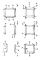
Figures 5 to 10 illustrate a possible operating sequence of the system inFigure 1 ; -
Figure 11 is a top view of a caulking device included in the system inFigure 1 ; -
Figure 12 is a partially sectioned view from below of the caulking device inFigure 11 ; -
Figure 13 is a longitudinal section of the caulking device inFigure 11 . - With reference to
Figure 1 , there is illustrated a system 1 used in the door and window industry for machining and assemblingcasings 2 of frames (Figure 10 ) such as, for example, windows, french windows, doors, shutters, and the like. - The system 1 comprises a
loading magazine 3 arranged for loading onto the caulking machine 1 section bars 4 (Figure 5 ) that have not yet been machined, for example extruded aluminium sections, arranged, once they have been finished, for being assembled to make acasing 2. - The
loading magazine 3 is provided with gripping means, which are not shown, which are arranged for firmly gripping the section bars 4 and for conveying the latter to a cutting/milling centre 5 positioned downstream of theloading magazine 3. - The cutting/
milling centre 5 is arranged for cutting and milling the unworked section bars 4 firmly gripped by the aforesaid gripping means. - The system 1 further comprises an
unloading magazine 6 positioned downstream of the cutting/milling centre 5 and arranged for receiving the semifinished section bars 4 from the latter. - The unloading
magazine 6 is provided with detecting means, that is not shown, arranged for detecting the presence of reject section bars 4. - If the detecting means detects the presence of reject section bars 4 the latter are conveyed by a
conveyor belt 7 to aremoval zone 8 where they are removed by anoperator 11. - The system 1 further comprises a handling station 9, facing the
unloading magazine 6, and provided with a firstanthropomorphic robot 10, for example an anthropomorphic robot with six controlled axes. - The
first robot 10 is arranged for removing the semifinished section bars 4 from the unloadingmagazine 6, positioning the semifinished section bars 4 in a cleaningstation 12 that eliminates possible chips present at the ends of the semifinished section bars 4 that could compromise successive assembly thereof, and for loading, without resting, the section bars 4 that have just been finished by the cleaningstation 12, in a drawer, which is not shown, of abuffer magazine 13. - The
buffer magazine 13 is provided with a plurality of drawers, arranged for each containing a group of section bars 4 intended for making adetermined casing 2. - In an embodiment of the invention, the
buffer magazine 13 comprises thirty-six drawers. - The
buffer magazine 13 comprises aloading side 15 where the section bars 4 removed from the unloadingmagazine 6 are positioned by thefirst robot 10 and an unloadingside 16, from which the section bars 4 are unloaded, as will be disclosed below. - For example, in use, a pair of full drawers are positioned on the unloading
side 16, each comprising acasing 2 to be assembled. - The system 1 further comprises a
supervisory computer 14 arranged for controlling thebuffer magazine 13. - In particular, the
supervisory computer 14 assigns a first free drawer of thebuffer magazine 13 to a group of section bars 4 coming from the unloadingmagazine 6 and arranged for making adeterminate casing 2. - The system 1 further comprises a
machine tool 200 arranged for assembling and machining the section bars 4 for making thecasings 2. - The
machine tool 200 comprises a first manipulatingunit 17, provided with a secondanthropomorphic robot 18, between the handling station 9 and the first manipulatingunit 17 there being interposed thebuffer magazine 13. - The
second robot 18 is provided with gripping means arranged for removing the section bars 4 contained in a full drawer positioned on the unloadingside 16 of thebuffer magazine 13, positioning them one at a time on anassembly unit 19 and subsequently arranged for inserting into the latter corner joints 38 (Figure 6 ) removed from a corner jointsmagazine 39. - It should be noted that the drawers that have just been emptied are transferred from the unloading
side 16 to theloading side 15 of thebuffer magazine 13 to be filled with further section bars 4. - Returning to the
assembly unit 19, shown schematically inFigures 2 and 3 , this is arranged for supporting, centring and assembling the section bars 4. - The
assembly unit 19, which is rotatable around a rotation axis Z, comprises a supportingframe body 20. - The supporting
frame body 20 comprises afirst frame 21 and asecond frame 22 that are opposite one another, each arranged for supporting and assembling the section bars 4 and supported by asupport 201 mounted on amotor 202. Subsequently there is disclosed in detail only thefirst frame 21, inasmuch as thesecond frame 22 is substantially and structurally similar to the latter. - The
first frame 21, shown inFigure 2 , comprises grasping means 40 arranged for grasping and moving the section bars 4. - The grasping means 40 comprises first grasping
means 51, second graspingmeans 52, third grasping means 53 and fourth grasping means 54 arranged for each grasping a respective section bar 4. - The first grasping means 51, the second grasping means 52, the third grasping means 53 and the fourth grasping means 54 are respectively positioned along a
first side 41, asecond side 42, athird side 43 and afourth side 44 of thefirst frame 21. - The
first frame 21 further comprises a centring device arranged for centring the section bars 4 on thefirst frame 21 to give precise references to thesecond robot 18. - The centring device comprises first centring means 46, second centring means, third centring means and fourth centring means, that are not shown, positioned substantially parallel to the
first side 41, to thesecond side 42, to thethird side 43 and to thefourth side 44 and substantially opposite respectively the first graspingmeans 51, the second grasping means 52, the third grasping means 53 and the fourth graspingmeans 54. - Only the first centring means 46 is disclosed below inasmuch as the second centring means, the third centring means and the fourth centring means are substantially, structurally and functionally similar.
- The first centring means 46, shown schematically in
Figure 4 , is arranged for defining a preset centring position W on thefirst work plane 21 for afirst section bar 36. - The first centring means 46 is provided with compensating
means 110 comprising afirst abutment 27 and asecond abutment 28 that are movable towards and away from one another through an forward and backward stroke of a preset length, along an operating direction X. - The
first abutment 27, being substantially L-shaped, comprises a firstactive surface 29 arranged, in use, for contacting afirst end 31 of thefirst section bar 36. - The
second abutment 28 comprises abase element 34 connected byelastic means 35 to a compensatingelement 66, arranged for compensating possible dimensional variations of the section bars 4. - The compensating
element 36 is in fact supported for sliding by guide means 32, associated with thebase element 34, and the compensatingelement 36 is movable along the operating direction X with respect to thebase element 34. - The compensating
element 66 comprises a secondactive surface 30, facing the firstactive surface 29 and arranged for contacting asecond end 33 of the section bar 4 opposite thefirst end 31. The firstactive surface 29 and the secondactive surface 30 cooperate to define the centring position W for thefirst section bar 36. - The operation of the first centring means 46 is disclosed below.
- Initially, the
second robot 18 removes from the buffer magazine 13 afirst section bar 36 and asecond section bar 56 and delivers thefirst section bar 36 and thesecond section bar 56 respectively to the first graspingmeans 51 and to the second grasping means 52, which grasp thefirst section bar 36 and thesecond section bar 56, without locking them. - It should be noted that once the
first section bar 36 and thesecond section bar 56 have been grasped by the first graspingmeans 51 and by the second grasping means 52, both the first graspingmeans 51 and the second grasping means 52 proceed substantially simultaneously to centre the respective section bars; the operation of the first centring means 46 only is disclosed below inasmuch as the second centring means operates in a substantially similar manner. After thefirst section bar 36 has been grasped by the first graspingmeans 51, the first centring means 46 is driven, for example by an actuating means, to position thefirst abutment 27 and thesecond abutment 28 in the preset centring position W. - Still subsequently, the first grasping
means 51 takes thefirst end 31 and thesecond end 33 of thefirst section bar 36 against the first centring means 46, which positions thefirst section bar 36 in the desired centring position W with respect to thefirst frame 21. - Possible dimensional variations of the
first section bar 36, due, for example, to thermal dilation/contraction, imprecise machining or the like that would compromise correct centring of thefirst section bar 36 on thefirst frame 21 are compensated by the compensatingelement 66, that is movable towards/away from thebase element 34 along the operating direction X. - Once centred, the
first section bar 36 is locked firmly by the first graspingmeans 51 and the first centring means 46 is positioned in a rest position. - Subsequently, the
second robot 18 inserts into suitable housings, which are not shown, obtained respectively in thefirst end 31 and in thesecond end 33 of the first section bar 36 a pair of corners joints 38 removed from the corner joints 39 magazine and into further housings that are not shown, obtained respectively in a third end 57 and into a fourth end 58 of the second section bar 56 a further pair of corner joints 38 (Figure 6 ). - It should be noted that in the case of section bars provided with thermal break, inserting four corners for each section bar can be provided.
- Subsequently, a
third section bar 59 and afourth section bar 60 that are opposite one another and interposed between thefirst section bar 36 and thesecond section bar 56 are loaded and centred on thefirst frame 21 in a similar manner to what has been disclosed above. - Still subsequently, the third grasping means 53 and the fourth grasping means 54, and with the third grasping means 53 and the fourth grasping means 54 the
third section bar 59 and thefourth section bar 60 are moved substantially parallel to the axis Z towards thesecond section bar 56 by the first graspingmeans 51, and then by thefirst section bar 36, moved in the direction indicated by the first arrow F1. - In this way the
first section bar 36, thesecond section bar 56, thethird section bar 59 and thefourth section bar 60 are compacted until thefirst section bar 36, thesecond section bar 56, thethird section bar 59 and thefourth section bar 60 form thecasing 2. - It should be noted that the information on the number and type of corner joints to be used is supplied to the
second robot 18 by thesupervisory computer 14. - After the
casing 2 has been compacted, theassembly unit 19 rotates around the rotation axis Z thereof by about 180°, in such a way that, on the one side, thefirst frame 21 faces a second manipulatingunit 67 arranged for subjecting the section bars 4 to a desired machining, such as, for example, caulking, gluing, broaching, drilling, screwing, and on the other side, thesecond work plane 22 faces thesecond robot 18. - In this way, whilst the second manipulating
unit 67 performs the aforesaid machinings, the first manipulatingunit 17, by thesecond robot 18, removes further section bars 4 contained in a further full drawer of thebuffer magazine 13 positioned on the unloadingside 16, positions the further section bars 4 one at a time on thesecond work plane 22, and assembles the further section bars 4 in a similar manner to what has been disclosed previously. - The second manipulating
unit 67 comprises a thirdanthropomorphic robot 68, provided with a caulking and gluingdevice 78, shown inFigures 11 to 13 , arranged for caulking and gluing the first corner 71, thesecond corner 72, the third corner 73 and thefourth corner 74 of thecasing 2. - The caulking and gluing
device 78 comprises a fixingflange 76, having a substantially circular shape, arranged for being fixed through threaded connecting means to thethird robot 68. - With the
flange 76 there is associated aconnection 77 arranged for supporting by means of a plurality of tubular elements 78 aframework 79, between theconnection 77 and theflange 76 there being interposedelastic elements 80. Theframework 79 is arranged for supporting respectively at afirst end portion 81 and at a second end portion 82 afirst caulking clamp 83 and asecond caulking clamp 84 arranged for caulking respectively section bars devoid of or provided with thermal break. - Only the
first clamp 83 is disclosed below, inasmuch as thesecond clamp 84 is substantially and functionally similar to the latter. - The
first clamp 83 comprises a pair ofjaws 85 that are rotatable around pin means 86. - The pin means 86 is associated with and projects from the
framework 79 and is arranged, in use, for removably engaging seat means 87 obtained in the supportingframe body 20 of theassembly unit 19. - In this way, in use, the caulking forces generated by the
first clamp 83 are discharged onto the supportingframe body 20 and not onto thethird robot 68. - Each
jaw 85 further comprises cam means 90 each arranged for engaging aroller 91. - The
roller 91 is moved by apresser 92 driven by apiston 94 and slidable along a guide of theframework 79. - In this way, by driving the
presser 92 theroller 91 is forced to slide along the cam means 90, closing and/or opening thejaws 85. - Each of the
jaws 85 further supports acaulking cutter 96 at an end thereof. - The caulking and gluing
device 78 further comprises anozzle 97 arranged for injecting into holes, which are not shown, obtained in the section bars 4 a desired quantity of glue, removed from a doser that is not shown and arranged for fixing the section bars 4 in a stable manner. - In an embodiment of the invention, which is not shown, the third
anthropomorphic robot 68 is provided with a drilling unit arranged for drilling said section bars 4. - In a further embodiment of the invention, which is not shown, the third
anthropomorphic robot 68 is provided with a broaching machine arranged for inserting broaches into the section bars 4. - In a still further embodiment of the invention, which is not shown, the third
anthropomorphic robot 68 is provided with a screwing head. - In another embodiment of the invention, which is not shown, also the
second robot 18 can be provided with a caulking and gluing device, with a drilling unit, with a broaching machine, and with a screwing head. - Once the
casing 2 has been fixed stably, thethird robot 68 rotates and drives a safety switch that stops the caulking machine 1 and opens anaccess door 100. - During opening of the access door 100 a
printing device 101 prints a recognition label on thecasing 2 that has just been made. - Subsequently, the
casing 2 that has just been made can be removed from thefirst frame 21. - Once the
casing 2 has been unloaded, theoperator 11 presses an end-of-unloading switch that closes theaccess door 100 and gives a signal to theassembly unit 19 by thesupervisory computer 14 to rotate the supportingframe body 20 to enable the second manipulatingunit 67 to fix thefurther casing 2 that was previously assembled by thesecond frame 22 and by thesecond robot 18. - Upstream of the first manipulating
unit 17 there can also be provided a spreading unit arranged for spreading a seal on the end portions of the section bars 4. - It should be noted that owing to the invention it is possible to make a highly automated machine tool that enables the metal section bars 2 to be centred, assembled and caulked automatically.
- Lastly, it should be noted that owing to the aforesaid invention it is possible to make a particularly versatile machine tool inasmuch as depending on the equipment mounted on the second manipulating
unit 67 it is possible to subject the section bars 4 to a plurality of machinings such as caulking, gluing, drilling, broaching and screwing.
Claims (15)
- Machine tool for assembling metal section bars (4) of casings (2) comprising an assembly unit (19) arranged for supporting and assembling said metal section bars (4), said assembly unit (19) being movable between a first operating position in which said metal section bars (4) are positionable on said assembly unit (19) and a second operating position in which said metal section bars (4) can be subjected to a desired machining, characterized in that said assembly unit (19) is rotatable around a rotation axis (Z) between said first operating position and said second operating position, said assembly unit (19) comprising supporting frame means (20) arranged for supporting said metal section bars (4) and said casings (2), said supporting frame means (20) comprises a first frame (21) and a second frame (22) positioned on sides opposite with respect to said rotation axis (Z).
- Machine according to claim 1, wherein at said first operating position there is provided a first manipulating unit (17) and at said second operating position there is provided a second manipulating unit (67), said assembly unit (19) being positioned between said first manipulating unit (17) and said second manipulating unit (67).
- Machine according to one of preceding claim, wherein said supporting frame means (20) comprises grasping means (40) arranged for grasping and moving said section bars (4) to assemble said casings (2).
- Machine according to claim 3, wherein said first frame (21) and/or said second frame (22) comprises said grasping means (40).
- Machine according to claim 3 or 4, wherein said grasping means (40) is provided on a first side (41), on a second side (42), on a third side (43), and on a fourth side (44) of said supporting frame means (20).
- Machine according to any one of preceding claims, and comprising centring means (46) associated with said supporting frame means (20) and arranged for centring said metal section bars (4) on said supporting frame means (20).
- Machine according to any one of claims 2 to 6, as claim 3 and claim 6 are appended to claim 2, wherein said first manipulating unit (17) and/or said second manipulating unit (67) comprise anthropomorphic robot means (18, 68).
- Machine according to claim 7, wherein in said first operating position said anthropomorphic robot means (18, 68) comprises gripping means arranged for inserting into a first end (31) and into a second end (33) of said section bar (4) connecting means (38) arranged for connecting said section bars (4).
- Machine according to claim 7 or 8, wherein in said second operating position said anthropomorphic robot means (18, 68) is provided with a drilling unit arranged for drilling said section bars (4) or with a broaching machine arranged for inserting broaches into said section bars (44) or with a screwing head or with caulking clamp means (78) arranged for caulking and gluing said section bars (4).
- Machine according to claim 9, and further comprising coupling means (86, 87) arranged for removably coupling said clamp means (78) with said supporting frame means (20).
- Machine according to any preceding claim, and further comprising a cutting and milling centre (5) arranged for cutting and milling said section bars (4).
- Machine according to claim 11, and further comprising a loading magazine (3) arranged for moving said section bars (4) to said cutting and milling centre (5) and an unloading magazine (6) arranged for receiving said section bars (4) from said cutting and milling centre (5).
- Machine according to any preceding claim, and further comprising a finishing device (12) arranged for removing from said section bars (4) possible machining chips.
- Machine according to claim 13 as appended to claim 12, and comprising handling means (10) arranged for transferring said section bars (4) from said unloading magazine (6) to said finishing device (12).
- Machine according to claim 13 or 14, and comprising a magazine (13) arranged for receiving said section bars (4) from said finishing device (12).
Applications Claiming Priority (2)
| Application Number | Priority Date | Filing Date | Title |
|---|---|---|---|
| IT000146A ITMO20060146A1 (en) | 2006-05-10 | 2006-05-10 | MACHINE TOOL |
| PCT/IB2007/001224 WO2007129215A2 (en) | 2006-05-10 | 2007-05-10 | Machine for assembling metal section bars of frames |
Publications (2)
| Publication Number | Publication Date |
|---|---|
| EP2021137A2 EP2021137A2 (en) | 2009-02-11 |
| EP2021137B1 true EP2021137B1 (en) | 2012-01-25 |
Family
ID=38564475
Family Applications (1)
| Application Number | Title | Priority Date | Filing Date |
|---|---|---|---|
| EP07734534A Not-in-force EP2021137B1 (en) | 2006-05-10 | 2007-05-10 | Machine for assembling metal section bars of frames |
Country Status (7)
| Country | Link |
|---|---|
| US (1) | US20090235514A1 (en) |
| EP (1) | EP2021137B1 (en) |
| CN (1) | CN101479059B (en) |
| AT (1) | ATE542632T1 (en) |
| IT (1) | ITMO20060146A1 (en) |
| RU (1) | RU2008148583A (en) |
| WO (1) | WO2007129215A2 (en) |
Families Citing this family (12)
| Publication number | Priority date | Publication date | Assignee | Title |
|---|---|---|---|---|
| CN105269325B (en) * | 2015-11-18 | 2017-10-24 | 长沙长泰机器人有限公司 | The robot workstation of aluminum alloy doorframe automation processing and processing method |
| CN106005513B (en) * | 2016-07-18 | 2018-08-21 | 西安科技大学 | A kind of device entering packing box for ballast finished product |
| CN107097051B (en) * | 2017-05-18 | 2023-10-27 | 金华职业技术学院 | Sunshade bracket pressing equipment |
| CN108406252B (en) * | 2018-05-14 | 2024-06-07 | 江苏大学 | Frame positioning and clamping integrated device for rectangular frame corner connector automatic assembly machine |
| CN112087908B (en) * | 2020-09-17 | 2021-08-31 | 安徽中巨机电设备有限公司 | Presetting method for electric appliance box body |
| CN111970882B (en) * | 2020-09-17 | 2021-08-31 | 安徽中巨机电设备有限公司 | Electric box body seam pre-fixing mechanism |
| FR3119559B1 (en) * | 2021-02-05 | 2022-12-30 | Goubin Jean Jacques | crimping head and installation for the assembly of profiles |
| CN113385588A (en) * | 2021-05-14 | 2021-09-14 | 安徽美沃门窗科技有限公司 | Corner collision machine convenient to maintain and used for machining aluminum alloy doors and windows |
| IT202200012940A1 (en) * | 2022-06-20 | 2023-12-20 | Kompany S R L | SYSTEM AND METHOD FOR THE PRODUCTION OF DOORS AND FRAMES FOR FIXTURES AND WINDOWS |
| CN116393991A (en) * | 2023-03-15 | 2023-07-07 | 山东理工大学 | Filter assembly line |
| CN117773545A (en) * | 2024-01-12 | 2024-03-29 | 浙江炬达机械有限公司 | An automatic assembly mechanism for the upper and lower cylinders of a lock cylinder |
| CN118578083B (en) * | 2024-06-17 | 2024-12-13 | 徐州金耀华门业有限公司 | Metal door frame processing assembly machine |
Family Cites Families (37)
| Publication number | Priority date | Publication date | Assignee | Title |
|---|---|---|---|---|
| US2663204A (en) * | 1947-10-24 | 1953-12-22 | Detroit Steel Products Co | Machine for making frames |
| US3681842A (en) * | 1971-01-26 | 1972-08-08 | Stacor Visionaire Corp | Automatic fastening machine |
| US3734381A (en) * | 1971-03-10 | 1973-05-22 | H Blevio | Apparatus for adhering and interlocking mitered molding strips to a panel |
| US3877132A (en) * | 1973-08-03 | 1975-04-15 | Marion O Fogle | Machine for assembling structures such as frames |
| DE2526857A1 (en) * | 1975-06-16 | 1976-12-30 | Hess Kg Maschbau Reinhold | Press for window and door frames - uses punches to join metal profiles to four corner pieces in one operation |
| US4175313A (en) * | 1978-04-20 | 1979-11-27 | Neumann Paul G | Method and apparatus for manufacturing door frames |
| US4258873A (en) * | 1978-07-03 | 1981-03-31 | Vela Charles C | Machine and method for stapling door fames |
| FR2512894B1 (en) * | 1981-09-16 | 1985-07-12 | Vanago Joseph | METHOD FOR ASSEMBLING MITER-CUT FRAMES AND DEVICES FOR IMPLEMENTING SAME |
| JPS5988230A (en) * | 1982-11-12 | 1984-05-22 | Matsushita Electric Ind Co Ltd | Assemble base |
| JPS60135149A (en) * | 1983-12-22 | 1985-07-18 | Sekisui Chem Co Ltd | Assembling of box structure |
| US4919586A (en) * | 1988-05-25 | 1990-04-24 | Grasp, Inc. | Mechanical closed loop robotic arm end effector positioning system |
| ATE122431T1 (en) * | 1989-02-09 | 1995-05-15 | Cassese Sa | DEVICE FOR ASSEMBLY OF FRAMES AND FRAMES. |
| ATA216389A (en) * | 1989-09-18 | 1991-06-15 | Actual Anlagen Maschinen Und W | FEED DEVICE FOR A CORNER PROCESSING MACHINE OR THE LIKE. FOR THE PROCESSING OF FRAMES WELDED FROM PLASTIC PROFILES, IN PARTICULAR WINDOW FRAMES |
| JPH0518165A (en) * | 1991-07-15 | 1993-01-26 | B B S Eng:Kk | Automatic assembling device for aluminum sash frame and the like |
| DE4138352C2 (en) * | 1991-11-21 | 2000-03-16 | Stuertz Maschbau | Method and device for producing rectangular frames |
| JPH07185966A (en) * | 1993-12-28 | 1995-07-25 | Nippei Toyama Corp | Frame assembly method and apparatus |
| CA2119308C (en) * | 1994-03-17 | 1996-12-24 | Walter Louis Grassi | Corner cleaning machine |
| JPH0957551A (en) * | 1995-08-11 | 1997-03-04 | Yaskawa Electric Corp | Apparatus and method for automatically assembling panel with frame |
| AT2655U1 (en) * | 1997-12-22 | 1999-02-25 | Technoplast Kunststofftechnik | DEVICE FOR PRODUCING WINDOW FRAMES |
| DE19813261B4 (en) * | 1998-03-25 | 2010-11-11 | Schüring GmbH & Co. Fenster-Technologie KG | Method and device for fastening a turn / tilt fitting |
| DE19832397C2 (en) * | 1998-07-18 | 2003-05-22 | Afs Holding Gmbh | Method and device for loading an m-head welding machine |
| US6089434A (en) * | 1999-02-26 | 2000-07-18 | Gleason Brothers Industries Inc. | Automatic frame maker |
| FR2799680B1 (en) * | 1999-10-14 | 2001-12-14 | Japp Inventeurs | AUTOMATIC FRAME ASSEMBLY MACHINE |
| US20030074786A1 (en) * | 1999-12-27 | 2003-04-24 | Marco Bellucci | Machine tool and method for working elongated elements, in particular metallic profiled elements |
| IT1319864B1 (en) * | 2000-03-17 | 2003-11-03 | Giuseppe Raffoni | DEVICE TO IMPLEMENT IN THE EQUIPMENT THAT REALIZE RECTANGULAR FRAMES, THE PERFECT COMBINATION OF THE STRIPS TO BE JOINED IN |
| AUPQ916600A0 (en) * | 2000-08-03 | 2000-08-24 | James Hardie Research Pty Limited | Automated manufactured apparatus for aluminium window/door systems |
| CA2449918A1 (en) * | 2002-11-19 | 2004-05-19 | Vinode Ramnauth | Apparatus and method for moving frameworks between workstations |
| EP1459821A1 (en) * | 2003-03-18 | 2004-09-22 | ATLA COOP. Soc. Coop. a r.l. | Device for crimping machine |
| DE20306257U1 (en) * | 2003-04-17 | 2004-08-19 | Kuka Schweissanlagen Gmbh | processing device |
| DE20318942U1 (en) * | 2003-12-04 | 2005-04-14 | Urban Gmbh & Co Maschinenbau Kg | trimming device |
| DE202004012786U1 (en) * | 2003-12-16 | 2005-05-04 | Urban Gmbh & Co. Maschinenbau Kg | Corner processing device for joints of profiled welded frames and/or frame parts, especially of window or door frames has cutting blade between two feelers resting on profile pieces; cutting blade can be moved relative to feelers |
| US7354227B2 (en) * | 2004-05-20 | 2008-04-08 | Pro-Line Automation Systems Ltd. | Apparatus and method for manufacturing plastic frameworks such as window frames |
| US7617578B2 (en) * | 2005-02-25 | 2009-11-17 | David Collins | Miter joint assembly system and method |
| DE202005011265U1 (en) * | 2005-07-14 | 2005-09-22 | SCHÜCO International KG | Production device for window or door frames has each corner connecting units mounted on column, and columns able to move relative to each other |
| US7784161B2 (en) * | 2006-03-27 | 2010-08-31 | Rotox Gmbh | Device for machining the corner area of a frame welded together out of profiled pieces |
| US7955458B2 (en) * | 2006-07-12 | 2011-06-07 | Ged Integrated Solutions, Inc. | Staging system for automated window or door fabrication |
| US8185240B2 (en) * | 2008-08-29 | 2012-05-22 | Williams Robotics, Llc | Automated apparatus for constructing assemblies of building components |
-
2006
- 2006-05-10 IT IT000146A patent/ITMO20060146A1/en unknown
-
2007
- 2007-05-10 CN CN2007800236563A patent/CN101479059B/en not_active Expired - Fee Related
- 2007-05-10 AT AT07734534T patent/ATE542632T1/en active
- 2007-05-10 RU RU2008148583/02A patent/RU2008148583A/en not_active Application Discontinuation
- 2007-05-10 WO PCT/IB2007/001224 patent/WO2007129215A2/en not_active Ceased
- 2007-05-10 US US12/300,139 patent/US20090235514A1/en not_active Abandoned
- 2007-05-10 EP EP07734534A patent/EP2021137B1/en not_active Not-in-force
Also Published As
| Publication number | Publication date |
|---|---|
| CN101479059B (en) | 2011-10-05 |
| CN101479059A (en) | 2009-07-08 |
| RU2008148583A (en) | 2010-06-20 |
| ITMO20060146A1 (en) | 2007-11-11 |
| US20090235514A1 (en) | 2009-09-24 |
| ATE542632T1 (en) | 2012-02-15 |
| WO2007129215A2 (en) | 2007-11-15 |
| EP2021137A2 (en) | 2009-02-11 |
| WO2007129215A3 (en) | 2008-06-19 |
Similar Documents
| Publication | Publication Date | Title |
|---|---|---|
| US20090235514A1 (en) | Machine for assembling metal section bars of frames | |
| EP2960016B1 (en) | A processing system and method for a work piece surface | |
| JP5630950B2 (en) | Automatic feeder for machine tool and operation method of automatic feeder | |
| JP2009066751A6 (en) | Automatic feeder for machine tool and operation method of automatic feeder | |
| EP2366479B1 (en) | A plant and a method for manufacturing frames of doors or windows | |
| EP2067586A2 (en) | Woodworking machine | |
| CN115673778B (en) | Profile feeding and cutting unit and corresponding profile processing equipment | |
| CN108555387B (en) | An automatic loading and unloading device for tongue and groove broaching of turbine disks | |
| JP5675623B2 (en) | Assembly for machining an object with a machining device and method for milling an object | |
| EP2991811A1 (en) | Machining center | |
| KR20060132979A (en) | Workpiece processing method and workpiece processing device for conveying systems with multiple surfaces | |
| EP1250213B1 (en) | Machine tool and method for working elongated elements, in particular metallic profiled elements | |
| CN107921597B (en) | Manufacturing module and method for operating a manufacturing module | |
| EP2025480B1 (en) | Machine for working door and window component parts of wood or similar | |
| EP2100718A1 (en) | Staging system for automated window or door fabrication | |
| CN116871450A (en) | Novel automatic riveting production process and device for disc buckle cross rod lock head | |
| CN216542146U (en) | Automatic accurate positioning and processing system for thick plate sample | |
| CN215469496U (en) | Automatic production system for sky rail | |
| CN210588036U (en) | Screw machine | |
| CN219335667U (en) | Pipe end machining equipment | |
| CN118180964A (en) | A material conveying channel and working method for processing door and window profiles | |
| CN215357453U (en) | Automatic production line for sky rail frame body | |
| CN210755536U (en) | High-efficiency circular sawing machine | |
| JPS59152054A (en) | Automatic preparation system | |
| CN112297018A (en) | Method and robot assembly for performing an operation on a target workpiece |
Legal Events
| Date | Code | Title | Description |
|---|---|---|---|
| PUAI | Public reference made under article 153(3) epc to a published international application that has entered the european phase |
Free format text: ORIGINAL CODE: 0009012 |
|
| 17P | Request for examination filed |
Effective date: 20081209 |
|
| AK | Designated contracting states |
Kind code of ref document: A2 Designated state(s): AT BE BG CH CY CZ DE DK EE ES FI FR GB GR HU IE IS IT LI LT LU LV MC MT NL PL PT RO SE SI SK TR |
|
| AX | Request for extension of the european patent |
Extension state: AL BA HR MK RS |
|
| RAP1 | Party data changed (applicant data changed or rights of an application transferred) |
Owner name: EMMEGI S.P.A. |
|
| 17Q | First examination report despatched |
Effective date: 20090305 |
|
| DAX | Request for extension of the european patent (deleted) | ||
| R17C | First examination report despatched (corrected) |
Effective date: 20090305 |
|
| RIN1 | Information on inventor provided before grant (corrected) |
Inventor name: CAIUMI, ANDREA |
|
| REG | Reference to a national code |
Ref country code: DE Ref legal event code: R079 Ref document number: 602007020233 Country of ref document: DE Free format text: PREVIOUS MAIN CLASS: B21D0053740000 Ipc: B23P0021000000 |
|
| RIC1 | Information provided on ipc code assigned before grant |
Ipc: B21D 53/74 20060101ALI20110708BHEP Ipc: B23P 19/00 20060101ALI20110708BHEP Ipc: B23P 21/00 20060101AFI20110708BHEP |
|
| GRAP | Despatch of communication of intention to grant a patent |
Free format text: ORIGINAL CODE: EPIDOSNIGR1 |
|
| GRAS | Grant fee paid |
Free format text: ORIGINAL CODE: EPIDOSNIGR3 |
|
| GRAA | (expected) grant |
Free format text: ORIGINAL CODE: 0009210 |
|
| AK | Designated contracting states |
Kind code of ref document: B1 Designated state(s): AT BE BG CH CY CZ DE DK EE ES FI FR GB GR HU IE IS IT LI LT LU LV MC MT NL PL PT RO SE SI SK TR |
|
| REG | Reference to a national code |
Ref country code: GB Ref legal event code: FG4D |
|
| REG | Reference to a national code |
Ref country code: CH Ref legal event code: EP |
|
| REG | Reference to a national code |
Ref country code: AT Ref legal event code: REF Ref document number: 542632 Country of ref document: AT Kind code of ref document: T Effective date: 20120215 |
|
| REG | Reference to a national code |
Ref country code: IE Ref legal event code: FG4D |
|
| REG | Reference to a national code |
Ref country code: DE Ref legal event code: R096 Ref document number: 602007020233 Country of ref document: DE Effective date: 20120322 |
|
| REG | Reference to a national code |
Ref country code: NL Ref legal event code: VDEP Effective date: 20120125 |
|
| LTIE | Lt: invalidation of european patent or patent extension |
Effective date: 20120125 |
|
| PG25 | Lapsed in a contracting state [announced via postgrant information from national office to epo] |
Ref country code: BG Free format text: LAPSE BECAUSE OF FAILURE TO SUBMIT A TRANSLATION OF THE DESCRIPTION OR TO PAY THE FEE WITHIN THE PRESCRIBED TIME-LIMIT Effective date: 20120425 Ref country code: BE Free format text: LAPSE BECAUSE OF FAILURE TO SUBMIT A TRANSLATION OF THE DESCRIPTION OR TO PAY THE FEE WITHIN THE PRESCRIBED TIME-LIMIT Effective date: 20120125 Ref country code: NL Free format text: LAPSE BECAUSE OF FAILURE TO SUBMIT A TRANSLATION OF THE DESCRIPTION OR TO PAY THE FEE WITHIN THE PRESCRIBED TIME-LIMIT Effective date: 20120125 Ref country code: LT Free format text: LAPSE BECAUSE OF FAILURE TO SUBMIT A TRANSLATION OF THE DESCRIPTION OR TO PAY THE FEE WITHIN THE PRESCRIBED TIME-LIMIT Effective date: 20120125 Ref country code: IS Free format text: LAPSE BECAUSE OF FAILURE TO SUBMIT A TRANSLATION OF THE DESCRIPTION OR TO PAY THE FEE WITHIN THE PRESCRIBED TIME-LIMIT Effective date: 20120525 |
|
| PG25 | Lapsed in a contracting state [announced via postgrant information from national office to epo] |
Ref country code: PT Free format text: LAPSE BECAUSE OF FAILURE TO SUBMIT A TRANSLATION OF THE DESCRIPTION OR TO PAY THE FEE WITHIN THE PRESCRIBED TIME-LIMIT Effective date: 20120525 Ref country code: GR Free format text: LAPSE BECAUSE OF FAILURE TO SUBMIT A TRANSLATION OF THE DESCRIPTION OR TO PAY THE FEE WITHIN THE PRESCRIBED TIME-LIMIT Effective date: 20120426 Ref country code: LV Free format text: LAPSE BECAUSE OF FAILURE TO SUBMIT A TRANSLATION OF THE DESCRIPTION OR TO PAY THE FEE WITHIN THE PRESCRIBED TIME-LIMIT Effective date: 20120125 Ref country code: FI Free format text: LAPSE BECAUSE OF FAILURE TO SUBMIT A TRANSLATION OF THE DESCRIPTION OR TO PAY THE FEE WITHIN THE PRESCRIBED TIME-LIMIT Effective date: 20120125 Ref country code: PL Free format text: LAPSE BECAUSE OF FAILURE TO SUBMIT A TRANSLATION OF THE DESCRIPTION OR TO PAY THE FEE WITHIN THE PRESCRIBED TIME-LIMIT Effective date: 20120125 |
|
| REG | Reference to a national code |
Ref country code: AT Ref legal event code: MK05 Ref document number: 542632 Country of ref document: AT Kind code of ref document: T Effective date: 20120125 |
|
| PG25 | Lapsed in a contracting state [announced via postgrant information from national office to epo] |
Ref country code: CY Free format text: LAPSE BECAUSE OF FAILURE TO SUBMIT A TRANSLATION OF THE DESCRIPTION OR TO PAY THE FEE WITHIN THE PRESCRIBED TIME-LIMIT Effective date: 20120125 |
|
| PG25 | Lapsed in a contracting state [announced via postgrant information from national office to epo] |
Ref country code: EE Free format text: LAPSE BECAUSE OF FAILURE TO SUBMIT A TRANSLATION OF THE DESCRIPTION OR TO PAY THE FEE WITHIN THE PRESCRIBED TIME-LIMIT Effective date: 20120125 Ref country code: RO Free format text: LAPSE BECAUSE OF FAILURE TO SUBMIT A TRANSLATION OF THE DESCRIPTION OR TO PAY THE FEE WITHIN THE PRESCRIBED TIME-LIMIT Effective date: 20120125 Ref country code: SE Free format text: LAPSE BECAUSE OF FAILURE TO SUBMIT A TRANSLATION OF THE DESCRIPTION OR TO PAY THE FEE WITHIN THE PRESCRIBED TIME-LIMIT Effective date: 20120125 Ref country code: CZ Free format text: LAPSE BECAUSE OF FAILURE TO SUBMIT A TRANSLATION OF THE DESCRIPTION OR TO PAY THE FEE WITHIN THE PRESCRIBED TIME-LIMIT Effective date: 20120125 Ref country code: DK Free format text: LAPSE BECAUSE OF FAILURE TO SUBMIT A TRANSLATION OF THE DESCRIPTION OR TO PAY THE FEE WITHIN THE PRESCRIBED TIME-LIMIT Effective date: 20120125 Ref country code: SI Free format text: LAPSE BECAUSE OF FAILURE TO SUBMIT A TRANSLATION OF THE DESCRIPTION OR TO PAY THE FEE WITHIN THE PRESCRIBED TIME-LIMIT Effective date: 20120125 |
|
| PG25 | Lapsed in a contracting state [announced via postgrant information from national office to epo] |
Ref country code: SK Free format text: LAPSE BECAUSE OF FAILURE TO SUBMIT A TRANSLATION OF THE DESCRIPTION OR TO PAY THE FEE WITHIN THE PRESCRIBED TIME-LIMIT Effective date: 20120125 |
|
| PLBE | No opposition filed within time limit |
Free format text: ORIGINAL CODE: 0009261 |
|
| STAA | Information on the status of an ep patent application or granted ep patent |
Free format text: STATUS: NO OPPOSITION FILED WITHIN TIME LIMIT |
|
| PG25 | Lapsed in a contracting state [announced via postgrant information from national office to epo] |
Ref country code: MC Free format text: LAPSE BECAUSE OF NON-PAYMENT OF DUE FEES Effective date: 20120531 |
|
| REG | Reference to a national code |
Ref country code: CH Ref legal event code: PL |
|
| 26N | No opposition filed |
Effective date: 20121026 |
|
| GBPC | Gb: european patent ceased through non-payment of renewal fee |
Effective date: 20120510 |
|
| PG25 | Lapsed in a contracting state [announced via postgrant information from national office to epo] |
Ref country code: CH Free format text: LAPSE BECAUSE OF NON-PAYMENT OF DUE FEES Effective date: 20120531 Ref country code: AT Free format text: LAPSE BECAUSE OF FAILURE TO SUBMIT A TRANSLATION OF THE DESCRIPTION OR TO PAY THE FEE WITHIN THE PRESCRIBED TIME-LIMIT Effective date: 20120125 Ref country code: LI Free format text: LAPSE BECAUSE OF NON-PAYMENT OF DUE FEES Effective date: 20120531 |
|
| REG | Reference to a national code |
Ref country code: DE Ref legal event code: R097 Ref document number: 602007020233 Country of ref document: DE Effective date: 20121026 |
|
| REG | Reference to a national code |
Ref country code: IE Ref legal event code: MM4A |
|
| REG | Reference to a national code |
Ref country code: FR Ref legal event code: ST Effective date: 20130131 |
|
| PG25 | Lapsed in a contracting state [announced via postgrant information from national office to epo] |
Ref country code: ES Free format text: LAPSE BECAUSE OF FAILURE TO SUBMIT A TRANSLATION OF THE DESCRIPTION OR TO PAY THE FEE WITHIN THE PRESCRIBED TIME-LIMIT Effective date: 20120506 Ref country code: FR Free format text: LAPSE BECAUSE OF NON-PAYMENT OF DUE FEES Effective date: 20120531 Ref country code: GB Free format text: LAPSE BECAUSE OF NON-PAYMENT OF DUE FEES Effective date: 20120510 Ref country code: IE Free format text: LAPSE BECAUSE OF NON-PAYMENT OF DUE FEES Effective date: 20120510 |
|
| PG25 | Lapsed in a contracting state [announced via postgrant information from national office to epo] |
Ref country code: MT Free format text: LAPSE BECAUSE OF FAILURE TO SUBMIT A TRANSLATION OF THE DESCRIPTION OR TO PAY THE FEE WITHIN THE PRESCRIBED TIME-LIMIT Effective date: 20120125 |
|
| PG25 | Lapsed in a contracting state [announced via postgrant information from national office to epo] |
Ref country code: TR Free format text: LAPSE BECAUSE OF FAILURE TO SUBMIT A TRANSLATION OF THE DESCRIPTION OR TO PAY THE FEE WITHIN THE PRESCRIBED TIME-LIMIT Effective date: 20120125 |
|
| PG25 | Lapsed in a contracting state [announced via postgrant information from national office to epo] |
Ref country code: LU Free format text: LAPSE BECAUSE OF NON-PAYMENT OF DUE FEES Effective date: 20120510 |
|
| PG25 | Lapsed in a contracting state [announced via postgrant information from national office to epo] |
Ref country code: HU Free format text: LAPSE BECAUSE OF FAILURE TO SUBMIT A TRANSLATION OF THE DESCRIPTION OR TO PAY THE FEE WITHIN THE PRESCRIBED TIME-LIMIT Effective date: 20070510 |
|
| PGFP | Annual fee paid to national office [announced via postgrant information from national office to epo] |
Ref country code: DE Payment date: 20190530 Year of fee payment: 13 Ref country code: IT Payment date: 20190523 Year of fee payment: 13 |
|
| REG | Reference to a national code |
Ref country code: DE Ref legal event code: R119 Ref document number: 602007020233 Country of ref document: DE |
|
| PG25 | Lapsed in a contracting state [announced via postgrant information from national office to epo] |
Ref country code: DE Free format text: LAPSE BECAUSE OF NON-PAYMENT OF DUE FEES Effective date: 20201201 |
|
| PG25 | Lapsed in a contracting state [announced via postgrant information from national office to epo] |
Ref country code: IT Free format text: LAPSE BECAUSE OF NON-PAYMENT OF DUE FEES Effective date: 20200510 |