EP2020590A2 - Apparatus for sensing position and/or torque - Google Patents
Apparatus for sensing position and/or torque Download PDFInfo
- Publication number
- EP2020590A2 EP2020590A2 EP08156904A EP08156904A EP2020590A2 EP 2020590 A2 EP2020590 A2 EP 2020590A2 EP 08156904 A EP08156904 A EP 08156904A EP 08156904 A EP08156904 A EP 08156904A EP 2020590 A2 EP2020590 A2 EP 2020590A2
- Authority
- EP
- European Patent Office
- Prior art keywords
- rotor assembly
- set forth
- shaft
- collectors
- flux
- Prior art date
- Legal status (The legal status is an assumption and is not a legal conclusion. Google has not performed a legal analysis and makes no representation as to the accuracy of the status listed.)
- Granted
Links
Images


Classifications
-
- G—PHYSICS
- G01—MEASURING; TESTING
- G01D—MEASURING NOT SPECIALLY ADAPTED FOR A SPECIFIC VARIABLE; ARRANGEMENTS FOR MEASURING TWO OR MORE VARIABLES NOT COVERED IN A SINGLE OTHER SUBCLASS; TARIFF METERING APPARATUS; MEASURING OR TESTING NOT OTHERWISE PROVIDED FOR
- G01D5/00—Mechanical means for transferring the output of a sensing member; Means for converting the output of a sensing member to another variable where the form or nature of the sensing member does not constrain the means for converting; Transducers not specially adapted for a specific variable
- G01D5/12—Mechanical means for transferring the output of a sensing member; Means for converting the output of a sensing member to another variable where the form or nature of the sensing member does not constrain the means for converting; Transducers not specially adapted for a specific variable using electric or magnetic means
- G01D5/14—Mechanical means for transferring the output of a sensing member; Means for converting the output of a sensing member to another variable where the form or nature of the sensing member does not constrain the means for converting; Transducers not specially adapted for a specific variable using electric or magnetic means influencing the magnitude of a current or voltage
- G01D5/142—Mechanical means for transferring the output of a sensing member; Means for converting the output of a sensing member to another variable where the form or nature of the sensing member does not constrain the means for converting; Transducers not specially adapted for a specific variable using electric or magnetic means influencing the magnitude of a current or voltage using Hall-effect devices
- G01D5/145—Mechanical means for transferring the output of a sensing member; Means for converting the output of a sensing member to another variable where the form or nature of the sensing member does not constrain the means for converting; Transducers not specially adapted for a specific variable using electric or magnetic means influencing the magnitude of a current or voltage using Hall-effect devices influenced by the relative movement between the Hall device and magnetic fields
-
- G—PHYSICS
- G01—MEASURING; TESTING
- G01L—MEASURING FORCE, STRESS, TORQUE, WORK, MECHANICAL POWER, MECHANICAL EFFICIENCY, OR FLUID PRESSURE
- G01L3/00—Measuring torque, work, mechanical power, or mechanical efficiency, in general
- G01L3/02—Rotary-transmission dynamometers
- G01L3/04—Rotary-transmission dynamometers wherein the torque-transmitting element comprises a torsionally-flexible shaft
- G01L3/10—Rotary-transmission dynamometers wherein the torque-transmitting element comprises a torsionally-flexible shaft involving electric or magnetic means for indicating
- G01L3/101—Rotary-transmission dynamometers wherein the torque-transmitting element comprises a torsionally-flexible shaft involving electric or magnetic means for indicating involving magnetic or electromagnetic means
- G01L3/104—Rotary-transmission dynamometers wherein the torque-transmitting element comprises a torsionally-flexible shaft involving electric or magnetic means for indicating involving magnetic or electromagnetic means involving permanent magnets
Definitions
- the present invention relates generally to apparatus for sensing position and/or torque and more particularly to an apparatus for sensing angular displacement between first and second rotating shafts.
- the relative displacement may be measured by a small angle displacement sensor.
- the relative position may then be used to derive the torque applied between the two shafts.
- power steering systems in motor vehicles and the like are designed to provide appropriate hydraulic or electrical assist to allow a driver to complete a turn of the motor vehicle.
- the driver typically turns a steering wheel which is connected to a first shaft.
- the first shaft is coupled to a second shaft which is connected to a steering mechanism.
- the first and second shafts may be coupled by a compliant member, such as a torsion bar.
- the first shaft may rotate with respect to the second shaft by a predetermined number of degrees, e.g., +/- 12 degrees. Mechanical stops may prevent further movement.
- the amount of assist is determined as a function of the amount of torque being applied to the first shaft.
- the magnetic circuit typically includes a second magnetic structure which forms a gap.
- a sensing device disposed within the gap, detects changes in the magnetic flux which is used as an indication of the relative displacement between the first and second shafts.
- Gandel The second magnetic structure in Gandel is made up of two ferromagnetic rings, each having a plurality of axially oriented teeth. Each ring includes a circular flux-closing zone, which is parallel to the flux-closing zone of the other ring. The teeth of the rings are generally perpendicular to the flux-closing zones and are interleaved.
- Gandel device is sensitive to mechanical misalignment during assembly. Specifically, the axial teeth of the rings require very accurate placement with respect to each other. A deviation in the relative position of the rings and teeth with respect to each other will cause reduced performance of the device. It is difficult to accurately align the teeth of the rings and to maintain their relative position to maintain the correct distance from tooth to tooth.
- Gandel device is sensitive to mechanical variation during operation.
- the device is sensitive to angular and parallel changes in the relationship of the two rotors to one another. Mechanical variation in these two directions will cause variation in the output.
- Gandel device Another disadvantage of the Gandel device is an output variation over 360°. This variation is caused by the magnetic structure of the device and the measurement location of the magnetosensitive elements.
- the present invention is aimed at one or more of the problems identified above.
- an apparatus for measuring the relative displacement between a first shaft and a second shaft includes a first rotor assembly, at least one magnet, a second rotor assembly, a flux collector and a sensing device.
- the first rotor assembly is coupled to the first shaft and is centered on an axis.
- the at least one magnet has a magnetic field and is disposed on the first rotor assembly.
- the second rotor assembly is coupled to the second shaft.
- the first and second rotor assemblies are coaxial.
- the second rotor assembly has a first stator plate and a second stator plate.
- the first and second stator plates have a circular base section and a plurality of teeth extending from the base section in a direction radial of the axis.
- the flux collector arrangement has a first collector and a second collector.
- the first and second collectors have a curved first surface.
- the curved first surface of the first and second collectors are spaced from an outer rim of the base section of the first and second stator plates, respectively.
- the first and second collectors having a second surface.
- the second surface of the first collector and the second surface of the second collector are parallel and form a gap.
- the sensing device is disposed within the gap for sensing a magnetic flux of the magnetic field.
- an apparatus for measuring the relative displacement between a first shaft and a second shaft includes a first and second rotor assemblies, a plurality of magnets, a second rotor assembly, a flux collector arrangement, and a sensing device.
- the first rotor assembly is coupled to the first shaft and is centered on an axis.
- the first rotor assembly has a circumference and a plurality of slots or flats spaced evenly around the circumference.
- the plurality of magnets have a magnetic field and are disposed on a respective slot or flat of the first rotor assembly.
- the second rotor assembly is coupled to the second shaft.
- the first and second rotor assemblies are coaxial.
- the second rotor assembly has a first stator plate and a second stator plate.
- the first and second stator plates have a circular base section and a plurality of teeth extending from the base section in a direction radial of the axis.
- the flux collector arrangement has a first collector and a second collector.
- the first and second collectors have a curved first surface spaced from an outer rim of the base section of the first and second stator plates, respectively.
- the first and second collectors have a tooth portion with a second surface and extend from the respective base section, the second surface of the tooth portion of the first collector and the second surface of the tooth portion of the second collector are parallel and form a gap.
- the sensing device is disposed within the gap for sensing a magnetic flux of the magnetic field.
- Figure 1A is an illustration of an apparatus for sensing a relative position between a first shaft and a second shaft, according to an embodiment of the present invention
- Figure 1B is an enlarged illustration of the position sensing apparatus of Figure 1A ;
- Figure 1C is a three-dimensional illustration of the position sensing apparatus of Figure 1A in a housing
- Figure 1D is a top view of the apparatus and housing of Figure 1C ;
- Figure 2A is a first cut away view of the apparatus of Figure 1A ;
- Figure 2B is a second cut away view of the apparatus of Figure 1A ;
- Figure 2C is a cut away view of a portion of a rotor assembly of the apparatus of Figure 1A ;
- Figure 2D is a second cut away view of a portion of a rotor assembly of the apparatus of Figure 1A ;
- Figure 3A is a three-dimensional view of a portion of a first and second rotor assembly of the apparatus of Figure 1A ;
- Figure 3B is a diagrammatic illustration of a position sensor and the apparatus of Figure 1A ;
- Figures 3C is a diagrammatic illustration of a position sensor with two sensing devices, according to an embodiment of the present invention.
- Figure 3D is a diagrammatic illustration of a position sensor with two sensing devices, according to an embodiment of the present invention.
- Figure 3E is an exemplary graph illustrating operation of the position sensor of Figure 3C ;
- Figure 3F is an exemplary graph illustrating operation of the position sensor of Figure 3D ;
- Figure 4 is a top view of the first and second rotor assemblies of Figure 3A ;
- Figure 5 is a side view of the first and second rotor assemblies of Figure 3A ;
- Figure 6 is an exemplary graph illustrating angle versus flux density of the apparatus of Figure 1A ;
- Figure 7A is a three-dimensional illustration of a first rotor assembly of the apparatus of Figure 1A , according to an embodiment of the present invention
- Figure 7B is a cut away view of the first rotor assembly Figure 7A ;
- Figure 7C is a side view of the first rotor assembly of Figure 7A ;
- Figure 7D is a diagrammatic illustration of a portion of a rotor of the first rotor assembly of Figure 7A ;
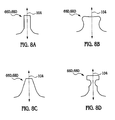
- Figure 8A is an illustration of a tooth of the second rotor assembly according to an embodiment of the present invention.
- Figure 8B is an illustration of a tooth of the second rotor assembly according to another embodiment of the present invention.
- Figure 8C is an illustration of a tooth of the second rotor assembly according to a further embodiment of the present invention.
- Figure 8D is an illustration of a tooth of the second rotor assembly according to still another embodiment of the present invention.
- Figure 9 is a diagrammatic illustration of an apparatus for sensing a relative position between a first shaft and a second shaft having a Z-shaped flux collector apparatus, according to an embodiment of the present invention.
- Figure 10 is a diagrammatic illustration of an apparatus for sensing a relative position between a first shaft and a second shaft having a Z-shaped flux collector apparatus, according to another embodiment of the present invention.
- Figure 11 is a diagrammatic illustration of an apparatus for sensing a relative position between a first shaft and a second shaft having a L-shaped flux collector apparatus, according to an embodiment of the present invention
- Figure 12 is a diagrammatic illustration of an apparatus for sensing a relative position between a first shaft and a second shaft having a L-shaped flux collector apparatus, according to another embodiment of the present invention.
- Figure 13 is a diagrammatic illustration of a first rotor arrangement of an apparatus for sensing a relative position between a first shaft and a second shaft, according to an embodiment of the present invention
- Figure 14 is a diagrammatic illustration of a first rotor arrangement of an apparatus for sensing a relative position between a first shaft and a second shaft, according to another embodiment of the present invention.
- Figure 15 is a diagrammatic illustration of an apparatus for sensing a relative position between a first shaft and a second shaft, according to an embodiment of the present invention
- Figure 16 is a diagrammatic illustration of a second rotor assembly of the apparatus of Figure 15 ;
- Figure 17 is a diagrammatic illustration of an Z-shaped flux collector, according to an embodiment of the present invention.
- Figure 18 is a cross-sectional view of the flux collector of Figure 17 ;
- Figure 19 is a diagrammatic illustration of an L-shaped flux collector, according to another embodiment of the present invention.
- Figure 20 is a second diagrammatic illustration of the L-shaped flux collector of Figure 19 ;
- Figure 21 is a diagrammatic illustration of an L-shaped flux collector, according to another embodiment of the present invention.
- Figure 22 is a diagrammatic illustration of an L-shaped flux collector, according to still another embodiment of the present invention.
- an apparatus 10 senses the relative position between a first shaft 12 and a second shaft 14. The relative position may then be used to derive the torque applied between the first and second shafts 12,14.
- the apparatus 10 may be used in an power steering system 16 to provide a measurement of input torque generated by a driver turning a steering wheel (not shown).
- the input torque is used to provide appropriate hydraulic or electrical assist to allow the driver to complete a turn with minimal effort, but increased stability.
- the first shaft 12 is connected to the steering wheel.
- the second shaft 14 is coupled to a steering system (not shown), for example, as a rack and pinion gear mechanism.
- a compliant member such as a torsion bar 18 couples the first and second shafts 12,14.
- the first and second shafts 12,14 are moveable relative to each other through a predetermined range, e.g., ⁇ 8 or ⁇ 12 degrees. It should be noted that the range of relative movement will be dependent upon application.
- the present invention is not limited to any given range of relative movement.
- a position sensor may be used to measure rotation of the first or second shafts 12,14.
- the position sensor may be a contact or noncontact sensor.
- the apparatus 10 may contained within a housing 22, which may also contain portions of the first and second shafts 12,14 and components of the power steering system. Such steering systems 16 are well known in the art and are, therefore, not further discussed.
- the apparatus 10 includes a first rotor assembly 24 and a second rotor assembly 26.
- the first rotor assembly 24 is coupled to the first shaft 12 and is centered on an axis 28.
- the second rotor assembly 26 is coupled to the second shaft 14.
- the first and second rotor assemblies 24,26 are coaxial.
- the apparatus 10 includes a flux collector apparatus 110 (see Figures 9 through 22 ) which is composed, at least partially, of steel or laminated steel.
- the flux collector apparatus 110 allows the sensor 10 to be more compact, reducing the size of, and/or the amount of material contained in, the other components.
- the first rotor assembly 24 includes a rotor 30 centered on the axis 28.
- the rotor 30 includes a plurality of slots or flats 32.
- the first rotor assembly 24 includes a plurality of magnets 34 located in each slot or flat 32.
- the magnets 34 may be affixed or held in place in any appropriate manner such as by an adhesive or crimping.
- a retaining member 36 may be used along with, or in place of, the adhesive.
- the retaining member 36 is made from a non-magnetic material, such as plastic.
- the retaining member 36 is overmolded the combined rotor 30 and magnets 34, once the magnets 34 are inserted into the slots or flats 32.
- the magnets may be arranged in a single ring around the rotor 30 (see Figure 13 ). In another embodiments, the magnets may be arranged in multiple rings, e.g., dual rings, around the rotor 30.
- the first rotor assembly 24 is pressed onto the first shaft 12.
- the first shaft 12 may have an enlarged portion 38 which forms a press-fit with the first rotor assembly 24.
- the first rotor 30 is composed of a soft magnetic material, such as a nickel iron alloy.
- the first rotor 30 may be made using a stamping process or may be made from a powdered metal using a sintering process or through a machining process.
- the rotor 30 includes an inner surface 40 and an outer surface 42.
- the slots or flats 32 are formed in the outer surface 42.
- the inner surface 40 has an associated inner radius 44 and the outer surface 42 has an associated outer radius 46.
- the rotor 30 forms support structures 48.
- the inner radius 44 is defined by the inner surface 40 at the center of a support structure 48. In one aspect of the present invention, the inner radius 44 is greater than outer radius 46.
- the magnets 34 are disposed evenly around the circumference of the rotor 30.
- the spacing between, i.e., the width of the support structures 48, the magnets 34 are approximately the width of the magnets 34 or slots or flats 32.
- the support structures 48 serves as the path the magnetic flux flows through to complete the magnetic circuit on its path through the magnets 34.
- top surface of the magnets 34 does not protrude beyond the support structures 48 in the axial direction.
- the rotor assembly 24 includes six square magnets 34, such as shown in Figure 12A .
- the front surface of the magnet 34 in Figure 12A is square. In an alternative embodiment, the front surface of the magnet 34 is rectangular.
- the front surface of the magnet 34 in Figure 12A is the North pole of the magnet 34.
- the back surface of the magnet 34 is the South pole.
- one of the front or back surface of the magnet 34 is adjacent the rotor 30.
- Four side surfaces adjoin the front and back surfaces of the magnets 34. At least one pair of edges formed by one of the front and back surfaces and the four side surfaces of the magnets 34 are rounded.
- all of the magnets 34 on the rotor are orientated in a similar manner, i.e., one of the North pole or the South pole is “down", i.e., adjacent the rotor 30, and the other pole, is "up”.
- the orientations of the magnets 34 are alternated, one magnet 34 is orientated “up” and the adjacent magnets 34 are orientated "down”.
- the first rotor assembly 24 may also include other magnet arrangements.
- the rotor assembly 24 may include two adjacent rows 50,52 of magnets 34.
- Each row 50,52 may include a plurality of magnets 34 spaced equidistantly around the circumference of the rotor 30.
- Each magnet 34 in one of the rows 50,52 may be orientated in the same direction or orientated in the opposite direction from the adjacent magnets.
- the rotor assembly 24 may include one or more ring magnets 54, as shown in Figure 12C .
- the ring magnet 54 has one or more pairs of adjacent poles 56, i.e., each pair having a North pole and a South pole. The North pole of one pair being adjacent the South pole of the next pair.
- the ring magnet 54 may have six pairs of North and South poles.
- the ring magnet 54 has an interior bore 58 which may surround the rotor 34.
- the ring magnet 54 may be affixed to the rotor 34 by an adhesive and/or the retaining member 36 and/or any suitable means. If more than one ring magnet 54 is provided, the ring magnets 54 are parallel.
- each magnet slot or flat 32 is defined by a plane 60.
- a centerpoint 62 of the plane 60 is tangent to the outer radius 46.
- Associated with each slot or flat 32 may also include stress relief slots 64. Additionally, a non-continuous inner diameter 47 may also eliminate hoop stress.
- the second rotor assembly 26 includes a first stator plate 66 and a second stator plate 68.
- the first and second stator plates 66,68 are parallel to each other.
- the first stator plate 66 includes an upper surface 66A and a lower surface 66B.
- the second stator plate 68 also includes an upper surface 68A and a lower surface 68B.
- the upper and lower surfaces 66A, 66B,68A, 68B are parallel.
- the lower surface 66B of the first stator plate 66 faces the upper surface 68A of the second stator plate 68, as shown.
- the first and second stator plates 66,68 may be manufactured using a stamping process may be made from a powdered metal using a sintering process, or may be made using a machining process.
- the first stator plate 66 includes a circular base 66C and a plurality of teeth 66D extending from the circular base 66C in a radial direction.
- the second stator plate 68 includes a circular base 68C and a plurality of teeth 68D extending from the circular base 68C in a radial direction.
- the teeth 66D,68D of the first and second stator plates 66,68 may be in-phase or offset from each other.
- the first and second plates 66,68 are planar. As shown in Figures 3A and 5 the upper surface of the teeth 66D,68D is co-planar with the upper surface 66A,68A of the respective stator plate 66,68 and the lower surface of the teeth 66D,68D is co-planar with the lower surface 66B,68B of the respective stator plate 66,68. In other words, the teeth 66D on the first stator plate 66 do not axially intersect with the teeth 68D on the second stator plate 68, i.e., do not intersect with a common plane perpendicular to the axis 28.
- the first and second stator plates 66,68 form a gap 70 between the lower surface 66B of the first stator plate 66 and the upper surface 68A of the second stator plate 68. As shown, the gap 70 has a uniform thickness.
- the second rotor assembly 26 includes a retaining member 72.
- the retaining member 72 is made form a non-magnetic material, such as plastic.
- the retaining member 72 is overmolded the first and second stator plates 66,68.
- the first stator plate 66 and the second stator plate 68 are retained by the retaining member 72 which fixes the relative position thereof.
- the retaining member 72 retains the first and second stator plates 66,68 in a predetermined relationship, i.e., to maintain the size of the desired gap 70 and the angular relationship between the first and second stator plates 66,68.
- the retaining member 72 also includes an inner bore 78.
- the retaining member 72 is slipped over the second shaft 14, the inner bore 78 forming a friction fit with the second shaft 14.
- the second shaft 14 may also include a number of splines (not shown) which form a spline interface with the retaining member 72.
- a retaining ring 80 fitted over an outer surface 82 of the retaining member 74 opposite the inner bore 78 may be used also as a redundant feature to retain the retaining member 72 on the second shaft 14.
- the apparatus 10 includes at least one sensing device 84 disposed within the gap 70 for sensing a change in magnetic flux.
- the sensing device 84 e.g., a hall effect sensor
- the sensing device 84 and the circuit board 86 are contained with a probe housing 88.
- the probe housing 88 is either mounted to a stationery member (not shown) or rotationally mounted to a bearing surface (not shown) and serves to accurately position the sensing device 84 within the gap 70.
- a wire harness 90 provides power and delivers signals from the sensing device 84. Alternately or additionally, a wedge gage plate, or screws may be used to assist in accurately positioning the sensing device 84 in the gap 70.
- the teeth 66D,68D of the first and second stator plates 66,68 are offset or out-phase.
- the magnetic field measured by the sensing device 84 varies depending on the alignment of the magnets in the first rotor assembly 24 and the teeth 68D,68D. As shown in Figure 4 , the radial gap between the teeth 66D,68D and the top of the magnets 34 is greater than the gap between the teeth 66D,68D and the top of the supporting structures 48.
- the magnetic circuit formed by the magnets has mainly two regions called upper magnetic zone formed between upper stator and the magnets and lower magnetic zone formed between lower stator and the magnets.
- the differential flux between these two zones flows through the measurement slot where magnetosensitive elements sense the field.
- both of the zones produce the same amount of flux, hence the differential flux crossing through the gap 70 is zero.
- the differential flux either flows up or down in the measurement slot.
- FIG. 6 an exemplary graph of flux density measured by the sensing device 84 as a function of angular displacement between the first and second shafts 12, 14 is shown. At zero degrees, no torque is being on the first shaft 12 and no flux is measured.
- the flux density measured by the sensing device 84 increases or decreases depending on the direction of travel of the first shaft 12.
- the maximum relative displacement between the first and second shafts 12, 14 is +/- ⁇ degrees with an associated -/-G Gauss of flux density variation. It should be noted that the graph of Figure 6 is exemplary and for illustrative purposes only.
- two sensing devices 84 may be used. Any changes in magnetic flux at constant displacement between the first and second rotor assemblies 24,26 over 360 degrees will have the same effect on each device 84.
- the spacing of the sensing devices 84 is dependent upon the number of magnetic poles and teeth of the first and second rotor assemblies 84, respectively.
- This variation will cause an oscillation of the output over 360 degrees which will appear with a frequency equal to the number of magnetic poles and stator teeth located on the first and second rotor assemblies.
- two sensing devices 84 may be used.
- this oscillation will have a 6th order ripple and will be referred to as a "6 per rev".
- This six per rev will appear in the signal from both sensing devices 84 (T1 and T2).
- the T1 and T2 signals have opposite polarities.
- the black rectangle inside the Hall sensors 84 represents the sensitive area of the device.
- the output signals are proportional to the normal component of the flux passing through the sensitive area. It is desirable that the oscillation affects the T1 and T2 signals in the same manner at the same time.
- the Hall sensors should be separated such that the oscillations in T 1 and T2 remain in phase (since they are inverted to each other).
- the ripple effect in the calculated torque signal is minimized. Due to mechanical packaging limitations with regard to the locations of the sensitive areas of the two Hall sensors with respect to each other, a certain phase shift exists between T1 and T2. This phase shift is shown in Figure 3C as ⁇ 1 .
- Figure 3E illustrates the T1 and T2 signals over 360 degrees with no compensation. In this particular embodiment our goal is to minimize the oscillation in the calculated torque signal.
- Figure 3D shows the implementation of this concept in the torque sensor.
- R is denoting the radial location of the Hall sensors from the axis of the shaft.
- Figure 3F illustrates the T1 and T2 signals after appropriately spacing the hall probes to minimize the ripple in the calculated torque signal.
- a non-contacting position sensor 92 may be used with the apparatus 10 for sensing the relative and/or absolute position of the first shaft 12 and the second shaft 14.
- the position sensor 92 which is shown diagrammatically, includes a ring magnet 94 magnetized diametrically resulting in two-pole (N-S) configuration.
- the ring magnet 94 and the ring shield 96 are concentric with the second shaft 12 and rotate therewith.
- the relative sensor section can detect 0-360 degrees in either direction of rotation.
- a disk magnet 98 magnetized through the diameter and a ring shield 10, which are external to the ring shield 96 and fixed relative to the first shaft.
- the disk magnet is used to provide absolute position of the shaft since the shaft can rotate ⁇ 810 degrees.
- the turns counter section of the sensor rotates in steps of 180 degrees revolution of the first shaft or the relative sensor section and connected there by Geneva wheel gear mechanism.
- both sensor section there are two Hall sensors placed at quadrature. They both use sine and cosine signals to extract position information.
- the teeth 66D,68D may have different shapes. Various examples of teeth 66D,68D are shown in Figures 8A, 8B, 8C, 8D . However, it should be noted that the present invention is not limited to any one shape of the teeth 66D,68D.
- the teeth 66D,68D may be in phase or out of phase. If the teeth 66D,68D are in-phase or aligned, a centerline 104 of the teeth 66D of the first stator plate 66 is aligned with a centerline 104 of the teeth 68D of the second stator plate 68. If the teeth 66D,68D are out-of phase, than the centerline 104 of the teeth 66D of the first stator plate 66 are offset from the centerline 104 of the teeth 68D of the second stator plate 68, as shown in Figures 3A and 4 .
- teeth 66D,68D are out-of-phase, there may be a radial gap between edges of the teeth 66D,68D as shown best in Figure 4 , the edges of the teeth 66D,68D may be aligned, or the teeth 66D,68D may at least partially overlap.
- edges of the teeth 66D,68D of one of the first and second stator plates 66,68 are adjacent with an edge of one of the teeth 66D,68D of the other of the first and second plates 66,68.
- the shape of the teeth 66D,68D is shown in Figure 8C .
- the flux collector apparatus 110 may have various shapes and/or sizes.
- the flux collector apparatus 110 includes a first collector 110A and a second collector 110B.
- Figures 9-12 and 17-22 illustrate different potential geometric shapes (includes sizes) of the first and second collectors 110A,110B.
- Each flux collector 110A,110B has a curved surface (best shown in Figures 10 and 17 ) 112.
- Each curved surface 112 is spaced from an outer rim 66G,68G of the base 66C,68C of the respective first and second stator plate 66,68.
- the first and second collectors 110A,110B each have a second surface 114A,114B, spaced from one another, forming a gap 118.
- the sensing device 102 is disposed within the gap 118.
- the first and second collectors 110A,110B are circular and surround, i.e., 360 degrees, the outer rim of the respective stator plate 66,68.
- the first and second collectors 110A,110B may have various cross-sectional shapes (see below).
- the first and second collectors 110A,110B surround less than 100% of the outer rim of the respective stator plate 66,68 ( ⁇ 360%) (see for example, Figures 10-12 , 17 , 19-22 .
- the first and second collectors 110A,110B may cover 1/6, i.e., 60 degrees, of the outer circumference of each stator plate 66,68.
- the size of the partial collector, i.e., the angular portion of the circumference covered by the collectors 110A,110B may be dependent upon the number of slots/poles of the apparatus 10.
- the first and second collectors 110A,110B may have an L-shaped cross section.
- the first and second collectors 110A, 10B each have a base section 116A, a tooth extension 116B and a side section 116C (as shown in Figure 18 ).
- the curved surface 112 is formed by the respective base section 116A and the second surface is formed by the respective tooth section 116B.
- each collectors 110A,110B is circular, surrounding or enclosing 360 degrees of the respective stator plate 66,68.
- each collector 110A,110B may cover only a portion, e.g., 60 degrees, of the respective stator plate 66,68.
- the base section 116A, tooth extension 116B, and side section 116C all cover the same portion (in degrees) of the respective stator plate 66,68.
- the tooth extension 116B may cover more or less of the respective stator plate 66,68.
- the base section 116A may cover 60 degrees and the tooth extension may cover 30 degrees (see for example, Figures 11 , 12 , and 20 ).
- the each collector 110A,110B may have an L-shaped cross section.
- the collectors 110A,110B are similar to the Z-shaped collectors 110A,110B, but lack the side sections 116C.
- the second surface 114A,114B is formed by the tooth extension 116B and is coplanar with the inner surface of the base section 116A.
- the second surfaces 114A,114B are spaced inward of the inner surface of the base section 116A such that the gap 118 is smaller.
- base section 116A of each collector 110A,110B is within the outer radius of the plates 66,68, while the tooth extension 116B extend outside of the outer radius of the plates 66,68.
- the tooth extensions 116B extend inward from the respective base section 116A such that the gap 118 is smaller.
- the flux collectors 110A,110B may be placed fully within/between the stator plates 66,68, i.e., within the outer radius thereof, partially within and partially outside of the stator plates 66,68, wholly outside of the stator plates 66,68.
- the flux collectors 110A,110B are uniformly thick along the axial direction to improve the radial field variation measured by the sensing device 102.
- each flux collector may have a square or rectangular cross-section.
Abstract


Description
- The present invention relates generally to apparatus for sensing position and/or torque and more particularly to an apparatus for sensing angular displacement between first and second rotating shafts.
- It is frequently important to measure or sense an angular displacement and/or relative torque between first and second shafts. The relative displacement may be measured by a small angle displacement sensor. The relative position may then be used to derive the torque applied between the two shafts.
- For example, power steering systems in motor vehicles and the like are designed to provide appropriate hydraulic or electrical assist to allow a driver to complete a turn of the motor vehicle. The driver typically turns a steering wheel which is connected to a first shaft. The first shaft is coupled to a second shaft which is connected to a steering mechanism. The first and second shafts may be coupled by a compliant member, such as a torsion bar. Typically, the first shaft may rotate with respect to the second shaft by a predetermined number of degrees, e.g., +/- 12 degrees. Mechanical stops may prevent further movement. The amount of assist is determined as a function of the amount of torque being applied to the first shaft.
- Many types of position sensors utilize one or more magnets for generating a magnetic field. The magnetic circuit typically includes a second magnetic structure which forms a gap. A sensing device, disposed within the gap, detects changes in the magnetic flux which is used as an indication of the relative displacement between the first and second shafts.
- One such system is disclosed in
US Patent Application 20040011138, published January 22, 2004 (hereafter "Gandel"). The second magnetic structure in Gandel is made up of two ferromagnetic rings, each having a plurality of axially oriented teeth. Each ring includes a circular flux-closing zone, which is parallel to the flux-closing zone of the other ring. The teeth of the rings are generally perpendicular to the flux-closing zones and are interleaved. - One inherent problem with the Gandel device is that it is sensitive to mechanical misalignment during assembly. Specifically, the axial teeth of the rings require very accurate placement with respect to each other. A deviation in the relative position of the rings and teeth with respect to each other will cause reduced performance of the device. It is difficult to accurately align the teeth of the rings and to maintain their relative position to maintain the correct distance from tooth to tooth.
- Another disadvantage of the Gandel device is that it is sensitive to mechanical variation during operation. The device is sensitive to angular and parallel changes in the relationship of the two rotors to one another. Mechanical variation in these two directions will cause variation in the output.
- Another disadvantage of the Gandel device is an output variation over 360°. This variation is caused by the magnetic structure of the device and the measurement location of the magnetosensitive elements.
- Another inherent problem with the rings of the Gandel device is that they are complex and difficult and costly to manufacture.
- Another continual concern with such sensors is cost and packaging. Applications for such sensors are continually be re-designed, modified and allotted less physical space. The sensors, thus, must be fit into a smaller space while maintaining required accuracy.
- The present invention is aimed at one or more of the problems identified above.
- In a first aspect of the present invention, an apparatus for measuring the relative displacement between a first shaft and a second shaft is provided. The apparatus includes a first rotor assembly, at least one magnet, a second rotor assembly, a flux collector and a sensing device. The first rotor assembly is coupled to the first shaft and is centered on an axis. The at least one magnet has a magnetic field and is disposed on the first rotor assembly. The second rotor assembly is coupled to the second shaft. The first and second rotor assemblies are coaxial. The second rotor assembly has a first stator plate and a second stator plate. The first and second stator plates have a circular base section and a plurality of teeth extending from the base section in a direction radial of the axis. The flux collector arrangement has a first collector and a second collector. The first and second collectors have a curved first surface. The curved first surface of the first and second collectors are spaced from an outer rim of the base section of the first and second stator plates, respectively. The first and second collectors having a second surface. The second surface of the first collector and the second surface of the second collector are parallel and form a gap. The sensing device is disposed within the gap for sensing a magnetic flux of the magnetic field.
- In a second of the present invention, an apparatus for measuring the relative displacement between a first shaft and a second shaft is provided. The apparatus includes a first and second rotor assemblies, a plurality of magnets, a second rotor assembly, a flux collector arrangement, and a sensing device. The first rotor assembly is coupled to the first shaft and is centered on an axis. The first rotor assembly has a circumference and a plurality of slots or flats spaced evenly around the circumference. The plurality of magnets have a magnetic field and are disposed on a respective slot or flat of the first rotor assembly. The second rotor assembly is coupled to the second shaft. The first and second rotor assemblies are coaxial. The second rotor assembly has a first stator plate and a second stator plate. The first and second stator plates have a circular base section and a plurality of teeth extending from the base section in a direction radial of the axis. The flux collector arrangement has a first collector and a second collector. The first and second collectors have a curved first surface spaced from an outer rim of the base section of the first and second stator plates, respectively. The first and second collectors have a tooth portion with a second surface and extend from the respective base section, the second surface of the tooth portion of the first collector and the second surface of the tooth portion of the second collector are parallel and form a gap. The sensing device is disposed within the gap for sensing a magnetic flux of the magnetic field.
- Other advantages of the present invention will be readily appreciated as the same becomes better understood by reference to the following detailed description when considered in connection with the accompanying drawings wherein:
-
Figure 1A is an illustration of an apparatus for sensing a relative position between a first shaft and a second shaft, according to an embodiment of the present invention; -
Figure 1B is an enlarged illustration of the position sensing apparatus ofFigure 1A ; -
Figure 1C is a three-dimensional illustration of the position sensing apparatus ofFigure 1A in a housing; -
Figure 1D is a top view of the apparatus and housing ofFigure 1C ; -
Figure 2A is a first cut away view of the apparatus ofFigure 1A ; -
Figure 2B is a second cut away view of the apparatus ofFigure 1A ; -
Figure 2C is a cut away view of a portion of a rotor assembly of the apparatus ofFigure 1A ; -
Figure 2D is a second cut away view of a portion of a rotor assembly of the apparatus ofFigure 1A ; -
Figure 3A is a three-dimensional view of a portion of a first and second rotor assembly of the apparatus ofFigure 1A ; -
Figure 3B is a diagrammatic illustration of a position sensor and the apparatus ofFigure 1A ; -
Figures 3C is a diagrammatic illustration of a position sensor with two sensing devices, according to an embodiment of the present invention; -
Figure 3D is a diagrammatic illustration of a position sensor with two sensing devices, according to an embodiment of the present invention; -
Figure 3E is an exemplary graph illustrating operation of the position sensor ofFigure 3C ; -
Figure 3F is an exemplary graph illustrating operation of the position sensor ofFigure 3D ; -
Figure 4 is a top view of the first and second rotor assemblies ofFigure 3A ; -
Figure 5 is a side view of the first and second rotor assemblies ofFigure 3A ; -
Figure 6 is an exemplary graph illustrating angle versus flux density of the apparatus ofFigure 1A ; -
Figure 7A is a three-dimensional illustration of a first rotor assembly of the apparatus ofFigure 1A , according to an embodiment of the present invention; -
Figure 7B is a cut away view of the first rotor assemblyFigure 7A ; -
Figure 7C is a side view of the first rotor assembly ofFigure 7A ; -
Figure 7D is a diagrammatic illustration of a portion of a rotor of the first rotor assembly ofFigure 7A ; -
Figure 8A is an illustration of a tooth of the second rotor assembly according to an embodiment of the present invention; -
Figure 8B is an illustration of a tooth of the second rotor assembly according to another embodiment of the present invention; -
Figure 8C is an illustration of a tooth of the second rotor assembly according to a further embodiment of the present invention; -
Figure 8D is an illustration of a tooth of the second rotor assembly according to still another embodiment of the present invention; -
Figure 9 is a diagrammatic illustration of an apparatus for sensing a relative position between a first shaft and a second shaft having a Z-shaped flux collector apparatus, according to an embodiment of the present invention; -
Figure 10 is a diagrammatic illustration of an apparatus for sensing a relative position between a first shaft and a second shaft having a Z-shaped flux collector apparatus, according to another embodiment of the present invention; -
Figure 11 is a diagrammatic illustration of an apparatus for sensing a relative position between a first shaft and a second shaft having a L-shaped flux collector apparatus, according to an embodiment of the present invention; -
Figure 12 is a diagrammatic illustration of an apparatus for sensing a relative position between a first shaft and a second shaft having a L-shaped flux collector apparatus, according to another embodiment of the present invention; -
Figure 13 is a diagrammatic illustration of a first rotor arrangement of an apparatus for sensing a relative position between a first shaft and a second shaft, according to an embodiment of the present invention; -
Figure 14 is a diagrammatic illustration of a first rotor arrangement of an apparatus for sensing a relative position between a first shaft and a second shaft, according to another embodiment of the present invention; -
Figure 15 is a diagrammatic illustration of an apparatus for sensing a relative position between a first shaft and a second shaft, according to an embodiment of the present invention; -
Figure 16 is a diagrammatic illustration of a second rotor assembly of the apparatus ofFigure 15 ; -
Figure 17 is a diagrammatic illustration of an Z-shaped flux collector, according to an embodiment of the present invention; -
Figure 18 is a cross-sectional view of the flux collector ofFigure 17 ; -
Figure 19 is a diagrammatic illustration of an L-shaped flux collector, according to another embodiment of the present invention; -
Figure 20 is a second diagrammatic illustration of the L-shaped flux collector ofFigure 19 ; -
Figure 21 is a diagrammatic illustration of an L-shaped flux collector, according to another embodiment of the present invention; and, -
Figure 22 is a diagrammatic illustration of an L-shaped flux collector, according to still another embodiment of the present invention. - With reference to the Figures and in operation, an
apparatus 10 senses the relative position between afirst shaft 12 and asecond shaft 14. The relative position may then be used to derive the torque applied between the first andsecond shafts - In the illustrated embodiment, the
apparatus 10 may be used in anpower steering system 16 to provide a measurement of input torque generated by a driver turning a steering wheel (not shown). The input torque is used to provide appropriate hydraulic or electrical assist to allow the driver to complete a turn with minimal effort, but increased stability. Thefirst shaft 12 is connected to the steering wheel. Thesecond shaft 14 is coupled to a steering system (not shown), for example, as a rack and pinion gear mechanism. As is known in the art, a compliant member such as atorsion bar 18 couples the first andsecond shafts second shafts - Mechanical stops 20 restrict further relative movement between the first and
second shafts second shafts apparatus 10 may contained within ahousing 22, which may also contain portions of the first andsecond shafts Such steering systems 16 are well known in the art and are, therefore, not further discussed. - In one aspect of the present invention, the
apparatus 10 includes afirst rotor assembly 24 and asecond rotor assembly 26. Thefirst rotor assembly 24 is coupled to thefirst shaft 12 and is centered on anaxis 28. Thesecond rotor assembly 26 is coupled to thesecond shaft 14. The first andsecond rotor assemblies - In another aspect of the present invention, the
apparatus 10 includes a flux collector apparatus 110 (seeFigures 9 through 22 ) which is composed, at least partially, of steel or laminated steel. Theflux collector apparatus 110 allows thesensor 10 to be more compact, reducing the size of, and/or the amount of material contained in, the other components. - With specific reference to
Figures 2A, 2B ,7A ,7B, 7C ,13 and 14 thefirst rotor assembly 24 includes arotor 30 centered on theaxis 28. In one embodiment, therotor 30 includes a plurality of slots orflats 32. Thefirst rotor assembly 24 includes a plurality ofmagnets 34 located in each slot or flat 32. - The
magnets 34 may be affixed or held in place in any appropriate manner such as by an adhesive or crimping. In one aspect of the present invention, a retainingmember 36 may be used along with, or in place of, the adhesive. The retainingmember 36 is made from a non-magnetic material, such as plastic. In one embodiment, the retainingmember 36 is overmolded the combinedrotor 30 andmagnets 34, once themagnets 34 are inserted into the slots orflats 32. - In one embodiment, the magnets may be arranged in a single ring around the rotor 30 (see
Figure 13 ). In another embodiments, the magnets may be arranged in multiple rings, e.g., dual rings, around therotor 30. - With specific reference to
Figures 2A and 2B , thefirst rotor assembly 24 is pressed onto thefirst shaft 12. As shown, thefirst shaft 12 may have anenlarged portion 38 which forms a press-fit with thefirst rotor assembly 24. - The
first rotor 30 is composed of a soft magnetic material, such as a nickel iron alloy. Thefirst rotor 30 may be made using a stamping process or may be made from a powdered metal using a sintering process or through a machining process. - The
rotor 30 includes aninner surface 40 and anouter surface 42. The slots orflats 32 are formed in theouter surface 42. Theinner surface 40 has an associatedinner radius 44 and theouter surface 42 has an associatedouter radius 46. In between the slots orflats 32, therotor 30 forms supportstructures 48. Theinner radius 44 is defined by theinner surface 40 at the center of asupport structure 48. In one aspect of the present invention, theinner radius 44 is greater thanouter radius 46. - In the illustrated embodiment, the
magnets 34 are disposed evenly around the circumference of therotor 30. The spacing between, i.e., the width of thesupport structures 48, themagnets 34 are approximately the width of themagnets 34 or slots orflats 32. Thesupport structures 48 serves as the path the magnetic flux flows through to complete the magnetic circuit on its path through themagnets 34. - As shown, in the illustrated embodiment, top surface of the
magnets 34 does not protrude beyond thesupport structures 48 in the axial direction. - In one embodiment, the
rotor assembly 24 includes sixsquare magnets 34, such as shown inFigure 12A . The front surface of themagnet 34 inFigure 12A is square. In an alternative embodiment, the front surface of themagnet 34 is rectangular. - The front surface of the
magnet 34 inFigure 12A is the North pole of themagnet 34. The back surface of themagnet 34 is the South pole. In the illustrated embodiment i.e., one of the front or back surface of themagnet 34 is adjacent therotor 30. Four side surfaces adjoin the front and back surfaces of themagnets 34. At least one pair of edges formed by one of the front and back surfaces and the four side surfaces of themagnets 34 are rounded. - In one embodiment, all of the
magnets 34 on the rotor are orientated in a similar manner, i.e., one of the North pole or the South pole is "down", i.e., adjacent therotor 30, and the other pole, is "up". In another embodiment, the orientations of themagnets 34 are alternated, onemagnet 34 is orientated "up" and theadjacent magnets 34 are orientated "down". - The
first rotor assembly 24 may also include other magnet arrangements. For example, with reference toFigure 12B , therotor assembly 24 may include two adjacent rows 50,52 ofmagnets 34. Each row 50,52 may include a plurality ofmagnets 34 spaced equidistantly around the circumference of therotor 30. Eachmagnet 34 in one of the rows 50,52 may be orientated in the same direction or orientated in the opposite direction from the adjacent magnets. Alternatively, therotor assembly 24 may include one or more ring magnets 54, as shown inFigure 12C . The ring magnet 54 has one or more pairs of adjacent poles 56, i.e., each pair having a North pole and a South pole. The North pole of one pair being adjacent the South pole of the next pair. For example, the ring magnet 54 may have six pairs of North and South poles. The ring magnet 54 has an interior bore 58 which may surround therotor 34. The ring magnet 54 may be affixed to therotor 34 by an adhesive and/or the retainingmember 36 and/or any suitable means. If more than one ring magnet 54 is provided, the ring magnets 54 are parallel. - The
rotor 34 is designed to eliminate hoop stress. Hoop stress is eliminated by the relationship between theinner radius 44 and theouter radius 46. As shown, therotor 34 has no sharp corners which will reduce wear on any manufacturing tools. In the illustrated embodiment, each magnet slot or flat 32 is defined by aplane 60. A centerpoint 62 of theplane 60 is tangent to theouter radius 46. Associated with each slot or flat 32 may also includestress relief slots 64. Additionally, a non-continuousinner diameter 47 may also eliminate hoop stress. - Returning to
Figures 2A, 2B ,3A ,4, 5 ,15 and 16 thesecond rotor assembly 26 includes afirst stator plate 66 and asecond stator plate 68. The first andsecond stator plates Figure 5 , thefirst stator plate 66 includes anupper surface 66A and alower surface 66B. Thesecond stator plate 68 also includes anupper surface 68A and alower surface 68B. The upper andlower surfaces lower surface 66B of thefirst stator plate 66 faces theupper surface 68A of thesecond stator plate 68, as shown. The first andsecond stator plates - As best shown in
Figures 3A and5 , in the illustrated embodiment thefirst stator plate 66 includes acircular base 66C and a plurality ofteeth 66D extending from thecircular base 66C in a radial direction. Likewise, thesecond stator plate 68 includes acircular base 68C and a plurality ofteeth 68D extending from thecircular base 68C in a radial direction. - As discussed below, the
teeth second stator plates - In the illustrated embodiment, the first and
second plates Figures 3A and5 the upper surface of theteeth upper surface respective stator plate teeth lower surface respective stator plate teeth 66D on thefirst stator plate 66 do not axially intersect with theteeth 68D on thesecond stator plate 68, i.e., do not intersect with a common plane perpendicular to theaxis 28. - As shown in
Figure 5 , the first andsecond stator plates gap 70 between thelower surface 66B of thefirst stator plate 66 and theupper surface 68A of thesecond stator plate 68. As shown, thegap 70 has a uniform thickness. - With specific reference to
Figures 2A, 2B ,2C, 2D , in one aspect of the present invention, thesecond rotor assembly 26 includes a retainingmember 72. The retainingmember 72 is made form a non-magnetic material, such as plastic. In one embodiment, the retainingmember 72 is overmolded the first andsecond stator plates first stator plate 66 and thesecond stator plate 68 are retained by the retainingmember 72 which fixes the relative position thereof. The retainingmember 72 retains the first andsecond stator plates gap 70 and the angular relationship between the first andsecond stator plates - The retaining
member 72 also includes aninner bore 78. The retainingmember 72 is slipped over thesecond shaft 14, theinner bore 78 forming a friction fit with thesecond shaft 14. Thesecond shaft 14 may also include a number of splines (not shown) which form a spline interface with the retainingmember 72. A retainingring 80 fitted over anouter surface 82 of the retainingmember 74 opposite theinner bore 78 may be used also as a redundant feature to retain the retainingmember 72 on thesecond shaft 14. - With particular reference to
Figures 1C, 1D , and2B , theapparatus 10 includes at least onesensing device 84 disposed within thegap 70 for sensing a change in magnetic flux. In the illustrated embodiment, thesensing device 84, e.g., a hall effect sensor, is mounted to acircuit board 86. Thesensing device 84 and thecircuit board 86 are contained with aprobe housing 88. Theprobe housing 88 is either mounted to a stationery member (not shown) or rotationally mounted to a bearing surface (not shown) and serves to accurately position thesensing device 84 within thegap 70. Awire harness 90 provides power and delivers signals from thesensing device 84. Alternately or additionally, a wedge gage plate, or screws may be used to assist in accurately positioning thesensing device 84 in thegap 70. - As discussed above, in the illustrated embodiment, the
teeth second stator plates sensing device 84 varies depending on the alignment of the magnets in thefirst rotor assembly 24 and theteeth Figure 4 , the radial gap between theteeth magnets 34 is greater than the gap between theteeth structures 48. - The magnetic circuit formed by the magnets has mainly two regions called upper magnetic zone formed between upper stator and the magnets and lower magnetic zone formed between lower stator and the magnets. The differential flux between these two zones flows through the measurement slot where magnetosensitive elements sense the field. Hence at no load torque condition, both of the zones produce the same amount of flux, hence the differential flux crossing through the
gap 70 is zero. Depending on the relative displacement (+/-8 degrees) the differential flux either flows up or down in the measurement slot. With reference toFigure 6 , an exemplary graph of flux density measured by thesensing device 84 as a function of angular displacement between the first andsecond shafts first shaft 12 and no flux is measured. As torque is applied to thefirst shaft 12, the flux density measured by thesensing device 84 increases or decreases depending on the direction of travel of thefirst shaft 12. As shown in the example ofFigure 6 , the maximum relative displacement between the first andsecond shafts Figure 6 is exemplary and for illustrative purposes only. - With particular reference to
Figures 3C, 3D, 3E, and 3F , twosensing devices 84 may be used. Any changes in magnetic flux at constant displacement between the first andsecond rotor assemblies device 84. The spacing of thesensing devices 84 is dependent upon the number of magnetic poles and teeth of the first andsecond rotor assemblies 84, respectively. In the illustrated embodiment, there are six magnets associated with thefirst rotor assembly 24 and six radial teeth in each stator in thesecond rotor assembly 26. Due to this particular magnetic structure, at constant torque conditions, the differential flux in the measurement zone will vary over 360 degrees. This variation will cause an oscillation of the output over 360 degrees which will appear with a frequency equal to the number of magnetic poles and stator teeth located on the first and second rotor assemblies. As shown inFigure 3C , twosensing devices 84 may be used. In the present embodiment, this oscillation will have a 6th order ripple and will be referred to as a "6 per rev". This six per rev will appear in the signal from both sensing devices 84 (T1 and T2). In this case, the T1 and T2 signals have opposite polarities. The black rectangle inside theHall sensors 84 represents the sensitive area of the device. The output signals are proportional to the normal component of the flux passing through the sensitive area. It is desirable that the oscillation affects the T1 and T2 signals in the same manner at the same time. Because of this, the Hall sensors should be separated such that the oscillations inT 1 and T2 remain in phase (since they are inverted to each other). By placing the oscillations of the T1 and T2 signals in phase, the ripple effect in the calculated torque signal is minimized. Due to mechanical packaging limitations with regard to the locations of the sensitive areas of the two Hall sensors with respect to each other, a certain phase shift exists between T1 and T2. This phase shift is shown inFigure 3C as θ1.Figure 3E illustrates the T1 and T2 signals over 360 degrees with no compensation. In this particular embodiment our goal is to minimize the oscillation in the calculated torque signal. By placing the two Hall probes 30 degrees apart shown as θ2 inFigure 3D , we can put the signals in phase to minimize the output oscillation calculated in the torque measurement.Figure 3D shows the implementation of this concept in the torque sensor. R is denoting the radial location of the Hall sensors from the axis of the shaft.Figure 3F illustrates the T1 and T2 signals after appropriately spacing the hall probes to minimize the ripple in the calculated torque signal. - With particular reference to
Figure 3B , in another aspect of the present invention, anon-contacting position sensor 92 may be used with theapparatus 10 for sensing the relative and/or absolute position of thefirst shaft 12 and thesecond shaft 14. Theposition sensor 92, which is shown diagrammatically, includes aring magnet 94 magnetized diametrically resulting in two-pole (N-S) configuration. Thering magnet 94 and thering shield 96 are concentric with thesecond shaft 12 and rotate therewith. The relative sensor section can detect 0-360 degrees in either direction of rotation. Adisk magnet 98 magnetized through the diameter and aring shield 10, which are external to thering shield 96 and fixed relative to the first shaft. The disk magnet is used to provide absolute position of the shaft since the shaft can rotate ±810 degrees. The turns counter section of the sensor rotates in steps of 180 degrees revolution of the first shaft or the relative sensor section and connected there by Geneva wheel gear mechanism. In both sensor section there are two Hall sensors placed at quadrature. They both use sine and cosine signals to extract position information. - The
teeth teeth Figures 8A, 8B, 8C, 8D . However, it should be noted that the present invention is not limited to any one shape of theteeth - As discussed above, the
teeth teeth centerline 104 of theteeth 66D of thefirst stator plate 66 is aligned with acenterline 104 of theteeth 68D of thesecond stator plate 68. If theteeth centerline 104 of theteeth 66D of thefirst stator plate 66 are offset from thecenterline 104 of theteeth 68D of thesecond stator plate 68, as shown inFigures 3A and4 . - If the
teeth teeth Figure 4 , the edges of theteeth teeth - For example, in one embodiment the edges of the
teeth second stator plates teeth second plates teeth Figure 8C . - In another embodiment, at least a portion of the edge of one of the
teeth teeth second plates - With particular reference to
Figures 9 through 22 , in another aspect of the present invention, theflux collector apparatus 110 may have various shapes and/or sizes. In one aspect of the present invention, theflux collector apparatus 110 includes afirst collector 110A and asecond collector 110B.Figures 9-12 and 17-22 illustrate different potential geometric shapes (includes sizes) of the first andsecond collectors flux collector Figures 10 and17 ) 112. Eachcurved surface 112 is spaced from anouter rim 66G,68G of thebase second stator plate second collectors second surface gap 118. In one aspect of the present invention, the sensing device 102 is disposed within thegap 118. - With particular reference to
Figure 9 , in one aspect, the first andsecond collectors respective stator plate second collectors - In another embodiment, the first and
second collectors respective stator plate 66,68 (< 360%) (see for example,Figures 10-12 ,17 ,19-22 . For example, the first andsecond collectors stator plate collectors apparatus 10. - With reference to
Figure 9, 10 ,17 and18 , the first andsecond collectors second collectors 110A, 10B each have abase section 116A, atooth extension 116B and aside section 116C (as shown inFigure 18 ). Thecurved surface 112 is formed by therespective base section 116A and the second surface is formed by therespective tooth section 116B. - With specific reference to
Figure 9 , eachcollectors respective stator plate - With specific reference to
Figure 10 , eachcollector respective stator plate base section 116A,tooth extension 116B, andside section 116C all cover the same portion (in degrees) of therespective stator plate tooth extension 116B may cover more or less of therespective stator plate base section 116A may cover 60 degrees and the tooth extension may cover 30 degrees (see for example,Figures 11 ,12 , and20 ). - With reference to
Figures 11 ,12 ,19, 20 , and22 , the eachcollector Figures 11 ,12 , and20 , thecollectors collectors side sections 116C. InFigure 11 , thesecond surface tooth extension 116B and is coplanar with the inner surface of thebase section 116A. InFigure 12 , thesecond surfaces base section 116A such that thegap 118 is smaller. - With specific reference to
Figure 21 ,base section 116A of eachcollector plates tooth extension 116B extend outside of the outer radius of theplates - With specific reference to
Figure 22 , thetooth extensions 116B extend inward from therespective base section 116A such that thegap 118 is smaller. - The
flux collectors stator plates stator plates stator plates - In one aspect of the present invention, the
flux collectors - Other shapes may also be used. For example, each flux collector may have a square or rectangular cross-section.
- Other variations in the
apparatus 10, including modifications/variations in the teeth, rotor, and stator plates may be found in commonly assignedU.S. Patent Nos. 7,158,233 and7,174,795 , both of which are hereby incorporated by reference. - Obviously, many modifications and variations of the present invention are possible in light of the above teachings. The invention may be practiced otherwise than as specifically described within the scope of the appended claims.
Claims (20)
- An apparatus for measuring the relative displacement between a first shaft and a second shaft, comprising:a first rotor assembly being coupled to the first shaft and being centered on an axis;at least one magnet having a magnetic field and being disposed on the first rotor assembly;a second rotor assembly being coupled to the second shaft, the first and second rotor assemblies being coaxial, the second rotor assembly having a first stator plate and a second stator plate, the first and second stator plates having a circular base section and a plurality of teeth extending from the base section in a direction radial of the axis;a flux collector arrangement having a first collector and a second collector, the first and second collectors having a curved first surface, the curved first surface of the first and second collectors being spaced from an outer rim of the base section of the first and second stator plates, respectively, the first and second collectors having a second surface, the second surface of the first collector and the second surface of the second collector being parallel and forming a gap; anda sensing device disposed within the gap for sensing a magnetic flux of the magnetic field.
- An apparatus, as set forth in claim 1, further comprising a compliant member coupled between the first and second shafts for allowing relative movement therebetween.
- An apparatus, as set forth in claim 1, further comprising a retaining member to hold the first and second stator plates and fixing the relative position thereof, respectively, and being fixedly coupled to the lower shaft.
- An apparatus, as set forth in claim 1, the sensing device being mounted to a stationery member or to a bearing surface.
- An apparatus, as set forth in claim 1, the first rotor assembly having a circumference and a plurality of slots or flats spaced evenly around the circumference, the apparatus including a plurality of magnets, each magnet being located in one of the slots or flats.
- An apparatus, as set forth in claim 5, each magnet having first and second parallel surfaces and four side surfaces, the first and second parallel surfaces being parallel to the axis, the first and second parallel surface being square.
- An apparatus, as set forth in claim 5, the plurality of magnets being in a single row around the circumference of the first rotor assembly.
- An apparatus, as set forth in claim 5, the plurality of magnets being in two rows around the circumference of the first rotor assembly.
- An apparatus, as set forth in claim 1, wherein the first and second flux collectors are circular, surrounding the outer rim of the respective stator plate.
- An apparatus, as set forth in claim 1, wherein the first and second flux collectors surround at least a portion of the outer rim of the respective stator plate.
- An apparatus, as set forth in claim 10, wherein each stator plate includes n teeth, and the first and second flux collectors surround 1/n of the outer rim of the respective stator plate.
- An apparatus, as set forth in claim 1, wherein the flux collectors have a Z-shaped cross-section.
- An apparatus, as set forth in claim 1, wherein the flux collectors have an L-shaped cross-section.
- An apparatus, as set forth in claim 1, wherein the flux collectors have a rectangular cross-section.
- An apparatus, as set forth in claim 1, wherein the flux collectors have a square cross-section.
- An apparatus, as set forth in claim 1, wherein the flux collectors have a base section and a tooth extension extending in a direction away from the base portion.
- An apparatus, as set forth in claim 1, wherein the first and second collectors are composed at least partially from steel.
- An apparatus, as set forth in claim 1, wherein the first and second collectors are composed at least partially from laminated steel.
- An apparatus for measuring the relative displacement between a first shaft and a second shaft, comprising:a first rotor assembly being coupled to the first shaft and being centered on an axis, the first rotor assembly having a circumference and a plurality of slots or flats spaced evenly around the circumference;a plurality of magnets having a magnetic field and being disposed on a respective slot or flat of the first rotor assembly;a second rotor assembly being coupled to the second shaft, the first and second rotor assemblies being coaxial, the second rotor assembly having a first stator plate and a second stator plate, the first and second stator plates having a circular base section and a plurality of teeth extending from the base section in a direction radial of the axis;a flux collector arrangement having a first collector and a second collector, the first and second collectors having a curved first surface, the curved first surface of the first and second collectors being spaced from an outer rim of the base section of the first and second stator plates, respectively, the first and second collectors having a tooth extension having a second surface and extending from the respective base section, the second surface of the tooth portion of the first collector and the second surface of the tooth portion of the second collector being parallel and forming a gap; anda sensing device disposed within the gap for sensing a magnetic flux of the magnetic field.
- An apparatus, as set forth in claim 19, wherein the magnets are in one or more rows around the circumference of the first rotor assembly.
Priority Applications (1)
| Application Number | Priority Date | Filing Date | Title |
|---|---|---|---|
| PL08156904T PL2020590T3 (en) | 2007-07-23 | 2008-05-26 | Apparatus for sensing position and/or torque |
Applications Claiming Priority (1)
| Application Number | Priority Date | Filing Date | Title |
|---|---|---|---|
| US11/880,502 US7639004B2 (en) | 2007-07-23 | 2007-07-23 | Apparatus for sensing angular displacement between first and second rotating shafts including flux collectors |
Publications (3)
| Publication Number | Publication Date |
|---|---|
| EP2020590A2 true EP2020590A2 (en) | 2009-02-04 |
| EP2020590A3 EP2020590A3 (en) | 2012-12-26 |
| EP2020590B1 EP2020590B1 (en) | 2015-05-06 |
Family
ID=39941772
Family Applications (1)
| Application Number | Title | Priority Date | Filing Date |
|---|---|---|---|
| EP20080156904 Active EP2020590B1 (en) | 2007-07-23 | 2008-05-26 | Apparatus for sensing position and/or torque |
Country Status (3)
| Country | Link |
|---|---|
| US (1) | US7639004B2 (en) |
| EP (1) | EP2020590B1 (en) |
| PL (1) | PL2020590T3 (en) |
Cited By (8)
| Publication number | Priority date | Publication date | Assignee | Title |
|---|---|---|---|---|
| DE102009045138A1 (en) * | 2009-09-30 | 2011-03-31 | Zf Friedrichshafen Ag | Arrangement for fastening sheet metal disk on planet carrier of automatic transmission of motor vehicle, has support ring including case on circumference, and component including retaining elements that are attached to case |
| CN103144666A (en) * | 2011-12-06 | 2013-06-12 | 万都株式会社 | Pinion sensor assembly, cover assembly, and electronic power steering apparatus |
| CN104048789A (en) * | 2013-03-15 | 2014-09-17 | 操纵技术Ip控股公司 | Non-contacting torque sensor with injection molded magnets |
| CN104169688A (en) * | 2012-03-30 | 2014-11-26 | 萱场工业株式会社 | Resolver |
| WO2016057305A1 (en) * | 2014-10-06 | 2016-04-14 | Tyco Electronics Corporation | Relative angle sensor |
| CN109631749A (en) * | 2019-01-04 | 2019-04-16 | 重庆理工大学 | Gating angular displacement sensor when a kind of absolute type |
| IT201800005590A1 (en) * | 2018-05-22 | 2019-11-22 | Wire transducer | |
| WO2020040562A1 (en) * | 2018-08-23 | 2020-02-27 | 엘지이노텍 주식회사 | Sensing device |
Families Citing this family (23)
| Publication number | Priority date | Publication date | Assignee | Title |
|---|---|---|---|---|
| US8087306B2 (en) * | 2006-12-07 | 2012-01-03 | Continental Teves Ag & Co. Ohg | Sensor arrangement for measuring a torque |
| DE102007057050A1 (en) * | 2007-01-29 | 2008-07-31 | Continental Teves Ag & Co. Ohg | Sensor arrangement i.e. torque sensor, for use in steering system of motor vehicle, has additional stator with two stator elements and arranged on shaft section, where stator is directly or indirectly assigned to magnetic encoder |
| JP5513838B2 (en) * | 2009-10-21 | 2014-06-04 | カヤバ工業株式会社 | Power steering device |
| KR101650455B1 (en) * | 2009-11-20 | 2016-08-23 | 엘지이노텍 주식회사 | Apparatus for detecting steering torque and steering angle of vehicle |
| CN102893071B (en) * | 2010-05-02 | 2015-10-07 | Mbs工程有限公司 | There is the assembly of the rotational stabilization of improvement and the magnet of axial stability and magnet keeper |
| US8726742B2 (en) * | 2010-11-23 | 2014-05-20 | Steering Solutions Ip Holding Corporation | Torque sensing system having torque sensor, and steering system |
| US8776619B2 (en) | 2011-11-18 | 2014-07-15 | Bourns, Inc. | Small angle sensor for measuring steering shaft torque |
| KR101913858B1 (en) * | 2011-12-06 | 2018-10-31 | 타이코에이엠피 주식회사 | The Torque sensor for measuring torsion of the steering column |
| US9013086B2 (en) | 2012-03-23 | 2015-04-21 | Whirlpool Corporation | Stator for an electric motor including separately formed end pieces and associated method |
| US9055719B2 (en) * | 2012-12-06 | 2015-06-16 | Deere & Company | Method and apparatus for ride control activation |
| CN103546067B (en) * | 2013-09-25 | 2016-01-13 | 清华大学 | A kind of Long Distances magnetic transportation by driving moving platform of big angle rotary |
| WO2015066993A1 (en) * | 2013-11-08 | 2015-05-14 | 中山大洋电机股份有限公司 | Installation structure for motor hall element |
| JP6295483B2 (en) * | 2014-09-19 | 2018-03-20 | 日立オートモティブシステムズ株式会社 | Power steering device and method of assembling power steering device |
| JP6330178B2 (en) * | 2014-11-19 | 2018-05-30 | 日立金属株式会社 | Torque steering angle sensor |
| US10794780B2 (en) * | 2015-10-08 | 2020-10-06 | Steering Solutions Ip Holding Corporation | Magnetic support structure of a torque sensor assembly including a central hub and a plurality of spoke segments extending radially outwardly from the central hub |
| JP6759704B2 (en) * | 2016-05-19 | 2020-09-23 | 株式会社ジェイテクト | Sensor unit and sensor device |
| US10330542B1 (en) * | 2017-04-20 | 2019-06-25 | Trw Automotive U.S. Llc | Torque sensor assembly for vehicle power steering systems |
| JP2019200119A (en) * | 2018-05-16 | 2019-11-21 | 株式会社東海理化電機製作所 | Magnetic field detector |
| KR102521179B1 (en) * | 2018-07-16 | 2023-04-13 | 엘지이노텍 주식회사 | Apparatus for sensing |
| FR3093181B1 (en) | 2019-02-25 | 2021-05-07 | Moving Magnet Tech | Position sensor, in particular intended for detecting the torsion of a steering column. |
| CN112109798A (en) | 2019-06-20 | 2020-12-22 | 操纵技术Ip控股公司 | Stray magnetic field cancellation for steering torque sensors |
| CN117118159A (en) * | 2019-12-04 | 2023-11-24 | Lg伊诺特有限公司 | Sensing device |
| CA3183403C (en) * | 2020-06-24 | 2023-08-01 | Carlos A. Hoefken | Magnetic field detection apparatus, system, and method |
Citations (3)
| Publication number | Priority date | Publication date | Assignee | Title |
|---|---|---|---|---|
| US20040011138A1 (en) | 2001-03-02 | 2004-01-22 | Pierre Gandel | Position sensor, designed in particular for detecting a steering column torsion |
| US7158233B2 (en) | 2001-09-17 | 2007-01-02 | Canon Kabushiki Kaisha | Alignment mark, alignment apparatus and method, exposure apparatus, and device manufacturing method |
| US7174795B2 (en) | 2004-02-06 | 2007-02-13 | Delphi Technologies, Inc. | Integrated non-contacting torque and absolute position sensor for steering applications |
Family Cites Families (31)
| Publication number | Priority date | Publication date | Assignee | Title |
|---|---|---|---|---|
| GB588677A (en) | 1945-02-12 | 1947-05-30 | Siemens Brothers & Co Ltd | Electrical arrangements for measuring small movements |
| US4672247A (en) | 1984-12-27 | 1987-06-09 | North American Philips Corporation | Synchronous or stepping motor with equal-torque stepping |
| US4784002A (en) | 1986-12-17 | 1988-11-15 | Atsugi Motor Parts Company, Limited | Torque sensor |
| US4984474A (en) | 1988-09-30 | 1991-01-15 | Copal Company Limited | Torque sensor |
| US4939456A (en) | 1988-12-23 | 1990-07-03 | General Motors Corporation | Position sensor including a thin film indium arsenide magnetoresistor on a permanent magnet |
| FR2691534B1 (en) | 1992-05-19 | 1994-08-26 | Moving Magnet Tech | Permanent magnet position sensor and hall sensor. |
| US5434504A (en) | 1993-10-01 | 1995-07-18 | International Business Machines Corporation | Position sensors for linear motors including plural symmetrical fluxes generated by a planar drive coil and received by planar sense coils being colinear along an axis of motion |
| FR2712982B1 (en) | 1993-11-26 | 1996-02-09 | Labinal | Differential torque measurement device. |
| US5627465A (en) | 1995-10-25 | 1997-05-06 | Honeywell Inc. | Rotational position sensor with mechanical adjustment of offset and gain signals |
| EP0774648B1 (en) | 1995-11-17 | 2000-07-12 | Leopold Kostal GmbH & Co. KG | Angle sensor |
| US5919241A (en) | 1996-12-13 | 1999-07-06 | General Motors Corporation | Vehicle having electric power steering with active damping |
| DE19816831A1 (en) | 1998-04-16 | 1999-10-21 | Bosch Gmbh Robert | System for determining torque acting on rotatable shaft with transmitter including 2 transmitter wheels which have differentiable angle markings esp. magnetic differentiable angle markings |
| DE19817886A1 (en) | 1998-04-22 | 1999-10-28 | Bosch Gmbh Robert | Arrangement for detecting torque acting on shaft |
| US6240678B1 (en) | 1998-07-09 | 2001-06-05 | Karl Heinz Spether | Capping head with torque adjustment |
| KR100308385B1 (en) | 1999-02-10 | 2001-09-26 | 밍 루 | Repelling power apparatus of a power streering system for a vehicle |
| JP3491596B2 (en) * | 1999-06-28 | 2004-01-26 | 株式会社デンソー | Rotation angle detector |
| DE19961884C2 (en) | 1999-12-20 | 2003-08-21 | Thomas Strothmann | Arrangement for contactless detection of angles of rotation, torques and other, preferably rotational quantities between rotating parts |
| JP3596667B2 (en) | 2000-01-26 | 2004-12-02 | 株式会社デンソー | Rotation angle detector |
| US6725734B1 (en) | 2001-07-25 | 2004-04-27 | The Furukawa Electric Co., Ltd. | Rotation sensor |
| US6546780B1 (en) | 2001-12-10 | 2003-04-15 | Delphi Technologies, Inc. | Position sensor method and apparatus |
| JP2004020527A (en) * | 2002-06-20 | 2004-01-22 | Nippon Soken Inc | Torque sensor |
| JP4085828B2 (en) | 2003-01-31 | 2008-05-14 | 株式会社ジェイテクト | Torque detection device |
| JP4111442B2 (en) | 2003-03-28 | 2008-07-02 | ミネベア株式会社 | Rotating body torque measuring device |
| JP4099094B2 (en) | 2003-03-28 | 2008-06-11 | ミネベア株式会社 | Rotating body torque measuring device |
| DE10316124A1 (en) * | 2003-04-04 | 2004-10-28 | Valeo Schalter Und Sensoren Gmbh | Device for determining a torque exerted on a shaft |
| US7021160B2 (en) * | 2003-06-10 | 2006-04-04 | Delphi Technologies, Inc. | Apparatus for sensing position and/or torque |
| US7021161B2 (en) | 2003-09-04 | 2006-04-04 | Delphi Technologies, Inc. | Gear bearing for a steering wheel position sensor |
| KR20050046245A (en) | 2003-11-13 | 2005-05-18 | 주식회사 만도 | Torque sensor for vehicle |
| JP3899086B2 (en) | 2004-05-11 | 2007-03-28 | ミネベア株式会社 | Rotating body torque measuring device |
| FR2872896B1 (en) * | 2004-07-09 | 2008-01-11 | Moving Magnet Tech | POSITION SENSOR, PARTICULARLY FOR MEASURING THE TORSION OF A STEERING COLUMN |
| JP2007187527A (en) * | 2006-01-12 | 2007-07-26 | Jtekt Corp | Torque detector |
-
2007
- 2007-07-23 US US11/880,502 patent/US7639004B2/en active Active
-
2008
- 2008-05-26 PL PL08156904T patent/PL2020590T3/en unknown
- 2008-05-26 EP EP20080156904 patent/EP2020590B1/en active Active
Patent Citations (3)
| Publication number | Priority date | Publication date | Assignee | Title |
|---|---|---|---|---|
| US20040011138A1 (en) | 2001-03-02 | 2004-01-22 | Pierre Gandel | Position sensor, designed in particular for detecting a steering column torsion |
| US7158233B2 (en) | 2001-09-17 | 2007-01-02 | Canon Kabushiki Kaisha | Alignment mark, alignment apparatus and method, exposure apparatus, and device manufacturing method |
| US7174795B2 (en) | 2004-02-06 | 2007-02-13 | Delphi Technologies, Inc. | Integrated non-contacting torque and absolute position sensor for steering applications |
Cited By (20)
| Publication number | Priority date | Publication date | Assignee | Title |
|---|---|---|---|---|
| DE102009045138A1 (en) * | 2009-09-30 | 2011-03-31 | Zf Friedrichshafen Ag | Arrangement for fastening sheet metal disk on planet carrier of automatic transmission of motor vehicle, has support ring including case on circumference, and component including retaining elements that are attached to case |
| CN103144666A (en) * | 2011-12-06 | 2013-06-12 | 万都株式会社 | Pinion sensor assembly, cover assembly, and electronic power steering apparatus |
| US8960364B2 (en) | 2011-12-06 | 2015-02-24 | Mando Corporation | Pinion sensor assembly, pinion sensor cover assembly, and electronic power steering apparatus having the same pipe |
| CN103144666B (en) * | 2011-12-06 | 2015-12-02 | 万都株式会社 | Miniature gears sensor module, casing assembly and electric power-assisted steering apparatus |
| CN104169688A (en) * | 2012-03-30 | 2014-11-26 | 萱场工业株式会社 | Resolver |
| EP2833099A1 (en) * | 2012-03-30 | 2015-02-04 | Kayaba Industry Co., Ltd. | Resolver |
| EP2833099A4 (en) * | 2012-03-30 | 2015-12-09 | Kayaba Industry Co Ltd | Resolver |
| US9395211B2 (en) | 2012-03-30 | 2016-07-19 | Kyb Corporation | Resolver for detecting rotational angle of motor |
| CN104048789B (en) * | 2013-03-15 | 2017-04-12 | 操纵技术Ip控股公司 | Non-contacting torque sensor with injection molded magnets |
| CN104048789A (en) * | 2013-03-15 | 2014-09-17 | 操纵技术Ip控股公司 | Non-contacting torque sensor with injection molded magnets |
| EP2778642A3 (en) * | 2013-03-15 | 2014-10-15 | Steering Solutions IP Holding Corporation | Non-contacting torque sensor with injection molded magnets |
| US8960020B2 (en) | 2013-03-15 | 2015-02-24 | Steering Solutions Ip Holding Corporation | Non-contacting torque sensor with injection molded magnets |
| WO2016057305A1 (en) * | 2014-10-06 | 2016-04-14 | Tyco Electronics Corporation | Relative angle sensor |
| US10036653B2 (en) | 2014-10-06 | 2018-07-31 | Te Connectivity Corporation | Relative angle sensor |
| IT201800005590A1 (en) * | 2018-05-22 | 2019-11-22 | Wire transducer | |
| WO2020040562A1 (en) * | 2018-08-23 | 2020-02-27 | 엘지이노텍 주식회사 | Sensing device |
| CN112601944A (en) * | 2018-08-23 | 2021-04-02 | Lg伊诺特有限公司 | Sensing device |
| US11719587B2 (en) | 2018-08-23 | 2023-08-08 | Lg Innotek Co., Ltd. | Sensing device |
| CN109631749A (en) * | 2019-01-04 | 2019-04-16 | 重庆理工大学 | Gating angular displacement sensor when a kind of absolute type |
| CN109631749B (en) * | 2019-01-04 | 2019-09-13 | 重庆理工大学 | Gating angular displacement sensor when a kind of absolute type |
Also Published As
| Publication number | Publication date |
|---|---|
| US20090027045A1 (en) | 2009-01-29 |
| EP2020590A3 (en) | 2012-12-26 |
| EP2020590B1 (en) | 2015-05-06 |
| PL2020590T3 (en) | 2015-10-30 |
| US7639004B2 (en) | 2009-12-29 |
Similar Documents
| Publication | Publication Date | Title |
|---|---|---|
| EP2020590B1 (en) | Apparatus for sensing position and/or torque | |
| EP1714123B1 (en) | Apparatus for sensing position and/or torque | |
| US9400290B2 (en) | Torque index sensor | |
| EP2511683B1 (en) | Torque sensor | |
| EP1437575A1 (en) | Multirotation type encoder | |
| EP2677280B1 (en) | Rotation angle detection device | |
| CN103154687A (en) | Device comprising a torque sensor and a rotation angle sensor | |
| EP2270456A2 (en) | Magnetic torque sensor | |
| EP2103910B1 (en) | Rotation angle detector | |
| JP2017015696A (en) | Relative angle detection device, torque sensor, electrically-driven power steering device and vehicle | |
| EP2088398B1 (en) | Rotation angle detector | |
| US5705756A (en) | Differential torque measuring device | |
| CN109256905A (en) | Toroidal magnet for rotor position estimate | |
| EP2587223A2 (en) | Magnetic encoder with improved resolution | |
| US7024946B2 (en) | Assembly for measuring movement of and a torque applied to a shaft | |
| JP6108009B2 (en) | Relative angle detection device, torque sensor, electric power steering device, and vehicle | |
| US7210360B2 (en) | Apparatus for sensing position and/or torque | |
| EP4202400A1 (en) | Sensing device | |
| JPH1028354A (en) | Motor with torque sensor | |
| JP5852485B2 (en) | Torque sensor | |
| JP7420840B2 (en) | Torque sensors, steering angle sensors and corresponding integrated sensors and monitoring systems | |
| JP2007278964A (en) | Rotary angle/torque detector |
Legal Events
| Date | Code | Title | Description |
|---|---|---|---|
| PUAI | Public reference made under article 153(3) epc to a published international application that has entered the european phase |
Free format text: ORIGINAL CODE: 0009012 |
|
| AK | Designated contracting states |
Kind code of ref document: A2 Designated state(s): AT BE BG CH CY CZ DE DK EE ES FI FR GB GR HR HU IE IS IT LI LT LU LV MC MT NL NO PL PT RO SE SI SK TR |
|
| AX | Request for extension of the european patent |
Extension state: AL BA MK RS |
|
| RAP1 | Party data changed (applicant data changed or rights of an application transferred) |
Owner name: GM GLOBAL TECHNOLOGY OPERATIONS, INC. |
|
| RAP1 | Party data changed (applicant data changed or rights of an application transferred) |
Owner name: GM GLOBAL TECHNOLOGY OPERATIONS LLC |
|
| PUAL | Search report despatched |
Free format text: ORIGINAL CODE: 0009013 |
|
| AK | Designated contracting states |
Kind code of ref document: A3 Designated state(s): AT BE BG CH CY CZ DE DK EE ES FI FR GB GR HR HU IE IS IT LI LT LU LV MC MT NL NO PL PT RO SE SI SK TR |
|
| AX | Request for extension of the european patent |
Extension state: AL BA MK RS |
|
| RAP1 | Party data changed (applicant data changed or rights of an application transferred) |
Owner name: STEERING SOLUTIONS IP HOLDING CORPORATION Owner name: GM GLOBAL TECHNOLOGY OPERATIONS LLC |
|
| RIC1 | Information provided on ipc code assigned before grant |
Ipc: G01L 3/10 20060101ALI20121119BHEP Ipc: G01D 5/14 20060101AFI20121119BHEP |
|
| 17P | Request for examination filed |
Effective date: 20130626 |
|
| RBV | Designated contracting states (corrected) |
Designated state(s): AT BE BG CH CY CZ DE DK EE ES FI FR GB GR HR HU IE IS IT LI LT LU LV MC MT NL NO PL PT RO SE SI SK TR |
|
| RBV | Designated contracting states (corrected) |
Designated state(s): AT BE BG CH CY CZ DE DK EE ES FI FR GB GR HR HU IE IS IT LI LT LU LV MC MT NL NO PL PT RO SE SI SK TR |
|
| AKX | Designation fees paid |
Designated state(s): DE FR PL |
|
| 17Q | First examination report despatched |
Effective date: 20130812 |
|
| GRAP | Despatch of communication of intention to grant a patent |
Free format text: ORIGINAL CODE: EPIDOSNIGR1 |
|
| INTG | Intention to grant announced |
Effective date: 20140627 |
|
| GRAP | Despatch of communication of intention to grant a patent |
Free format text: ORIGINAL CODE: EPIDOSNIGR1 |
|
| INTG | Intention to grant announced |
Effective date: 20141204 |
|
| GRAS | Grant fee paid |
Free format text: ORIGINAL CODE: EPIDOSNIGR3 |
|
| GRAA | (expected) grant |
Free format text: ORIGINAL CODE: 0009210 |
|
| AK | Designated contracting states |
Kind code of ref document: B1 Designated state(s): DE FR PL |
|
| REG | Reference to a national code |
Ref country code: FR Ref legal event code: PLFP Year of fee payment: 8 |
|
| REG | Reference to a national code |
Ref country code: DE Ref legal event code: R096 Ref document number: 602008038015 Country of ref document: DE Effective date: 20150618 |
|
| REG | Reference to a national code |
Ref country code: PL Ref legal event code: T3 |
|
| REG | Reference to a national code |
Ref country code: DE Ref legal event code: R097 Ref document number: 602008038015 Country of ref document: DE |
|
| PLBE | No opposition filed within time limit |
Free format text: ORIGINAL CODE: 0009261 |
|
| STAA | Information on the status of an ep patent application or granted ep patent |
Free format text: STATUS: NO OPPOSITION FILED WITHIN TIME LIMIT |
|
| 26N | No opposition filed |
Effective date: 20160209 |
|
| REG | Reference to a national code |
Ref country code: FR Ref legal event code: PLFP Year of fee payment: 9 |
|
| PGFP | Annual fee paid to national office [announced via postgrant information from national office to epo] |
Ref country code: FR Payment date: 20160530 Year of fee payment: 9 Ref country code: PL Payment date: 20160510 Year of fee payment: 9 |
|
| REG | Reference to a national code |
Ref country code: FR Ref legal event code: ST Effective date: 20180131 |
|
| PG25 | Lapsed in a contracting state [announced via postgrant information from national office to epo] |
Ref country code: FR Free format text: LAPSE BECAUSE OF NON-PAYMENT OF DUE FEES Effective date: 20170531 |
|
| PG25 | Lapsed in a contracting state [announced via postgrant information from national office to epo] |
Ref country code: PL Free format text: LAPSE BECAUSE OF NON-PAYMENT OF DUE FEES Effective date: 20170526 |
|
| PGFP | Annual fee paid to national office [announced via postgrant information from national office to epo] |
Ref country code: DE Payment date: 20230530 Year of fee payment: 16 |