EP2020501A2 - Heat exchanger housing, heat exchanger or component with one or more heat exchangers, exhaust gas recycling system, charge air supply system and use of the heat exchanger - Google Patents
Heat exchanger housing, heat exchanger or component with one or more heat exchangers, exhaust gas recycling system, charge air supply system and use of the heat exchanger Download PDFInfo
- Publication number
- EP2020501A2 EP2020501A2 EP08012978A EP08012978A EP2020501A2 EP 2020501 A2 EP2020501 A2 EP 2020501A2 EP 08012978 A EP08012978 A EP 08012978A EP 08012978 A EP08012978 A EP 08012978A EP 2020501 A2 EP2020501 A2 EP 2020501A2
- Authority
- EP
- European Patent Office
- Prior art keywords
- heat exchanger
- fluid
- housing
- housing body
- exhaust gas
- Prior art date
- Legal status (The legal status is an assumption and is not a legal conclusion. Google has not performed a legal analysis and makes no representation as to the accuracy of the status listed.)
- Granted
Links
Images
Classifications
-
- F—MECHANICAL ENGINEERING; LIGHTING; HEATING; WEAPONS; BLASTING
- F02—COMBUSTION ENGINES; HOT-GAS OR COMBUSTION-PRODUCT ENGINE PLANTS
- F02B—INTERNAL-COMBUSTION PISTON ENGINES; COMBUSTION ENGINES IN GENERAL
- F02B29/00—Engines characterised by provision for charging or scavenging not provided for in groups F02B25/00, F02B27/00 or F02B33/00 - F02B39/00; Details thereof
- F02B29/04—Cooling of air intake supply
- F02B29/045—Constructional details of the heat exchangers, e.g. pipes, plates, ribs, insulation, materials, or manufacturing and assembly
- F02B29/0462—Liquid cooled heat exchangers
-
- F—MECHANICAL ENGINEERING; LIGHTING; HEATING; WEAPONS; BLASTING
- F02—COMBUSTION ENGINES; HOT-GAS OR COMBUSTION-PRODUCT ENGINE PLANTS
- F02M—SUPPLYING COMBUSTION ENGINES IN GENERAL WITH COMBUSTIBLE MIXTURES OR CONSTITUENTS THEREOF
- F02M26/00—Engine-pertinent apparatus for adding exhaust gases to combustion-air, main fuel or fuel-air mixture, e.g. by exhaust gas recirculation [EGR] systems
- F02M26/13—Arrangement or layout of EGR passages, e.g. in relation to specific engine parts or for incorporation of accessories
- F02M26/22—Arrangement or layout of EGR passages, e.g. in relation to specific engine parts or for incorporation of accessories with coolers in the recirculation passage
- F02M26/23—Layout, e.g. schematics
- F02M26/25—Layout, e.g. schematics with coolers having bypasses
-
- F—MECHANICAL ENGINEERING; LIGHTING; HEATING; WEAPONS; BLASTING
- F02—COMBUSTION ENGINES; HOT-GAS OR COMBUSTION-PRODUCT ENGINE PLANTS
- F02M—SUPPLYING COMBUSTION ENGINES IN GENERAL WITH COMBUSTIBLE MIXTURES OR CONSTITUENTS THEREOF
- F02M26/00—Engine-pertinent apparatus for adding exhaust gases to combustion-air, main fuel or fuel-air mixture, e.g. by exhaust gas recirculation [EGR] systems
- F02M26/13—Arrangement or layout of EGR passages, e.g. in relation to specific engine parts or for incorporation of accessories
- F02M26/22—Arrangement or layout of EGR passages, e.g. in relation to specific engine parts or for incorporation of accessories with coolers in the recirculation passage
- F02M26/29—Constructional details of the coolers, e.g. pipes, plates, ribs, insulation or materials
- F02M26/32—Liquid-cooled heat exchangers
-
- F—MECHANICAL ENGINEERING; LIGHTING; HEATING; WEAPONS; BLASTING
- F28—HEAT EXCHANGE IN GENERAL
- F28F—DETAILS OF HEAT-EXCHANGE AND HEAT-TRANSFER APPARATUS, OF GENERAL APPLICATION
- F28F9/00—Casings; Header boxes; Auxiliary supports for elements; Auxiliary members within casings
-
- F—MECHANICAL ENGINEERING; LIGHTING; HEATING; WEAPONS; BLASTING
- F28—HEAT EXCHANGE IN GENERAL
- F28F—DETAILS OF HEAT-EXCHANGE AND HEAT-TRANSFER APPARATUS, OF GENERAL APPLICATION
- F28F2250/00—Arrangements for modifying the flow of the heat exchange media, e.g. flow guiding means; Particular flow patterns
- F28F2250/06—Derivation channels, e.g. bypass
-
- Y—GENERAL TAGGING OF NEW TECHNOLOGICAL DEVELOPMENTS; GENERAL TAGGING OF CROSS-SECTIONAL TECHNOLOGIES SPANNING OVER SEVERAL SECTIONS OF THE IPC; TECHNICAL SUBJECTS COVERED BY FORMER USPC CROSS-REFERENCE ART COLLECTIONS [XRACs] AND DIGESTS
- Y02—TECHNOLOGIES OR APPLICATIONS FOR MITIGATION OR ADAPTATION AGAINST CLIMATE CHANGE
- Y02T—CLIMATE CHANGE MITIGATION TECHNOLOGIES RELATED TO TRANSPORTATION
- Y02T10/00—Road transport of goods or passengers
- Y02T10/10—Internal combustion engine [ICE] based vehicles
- Y02T10/12—Improving ICE efficiencies
Definitions
- the invention relates to a heat exchanger housing for at least one heat exchanger for heat exchange between a first fluid and a second fluid. Furthermore, the invention relates to a heat exchanger or a structural unit with one or more heat exchangers for heat exchange between a first fluid and a second fluid. The invention also relates to an exhaust gas recirculation system, a charge air supply system and a use of the heat exchanger or the structural unit.
- Exhaust gas recirculation or charge air supply in particular with cooled exhaust gas and / or charge air, is used in current vehicles due to legal provisions in order to reduce particulate matter and pollutants, in particular nitrogen oxide emissions.
- the requirements for the exhaust gas pollution control and the exhaust gas mass flows to be managed increase, on the other hand, such systems and in particular the necessary heat exchanger developments are highly cost-driven.
- a heat exchanger is basically used for heat exchange between a first fluid, in particular an exhaust gas in the case of an exhaust gas cooler or a charge air in the case of a charge air cooler, and a second fluid, in particular a coolant, for example a water-based coolant or other liquid or gaseous coolant.
- a first fluid in particular an exhaust gas in the case of an exhaust gas cooler or a charge air in the case of a charge air cooler
- a second fluid in particular a coolant, for example a water-based coolant or other liquid or gaseous coolant.
- exhaust gas coolers are optionally removed with a bypass tube to achieve the operating temperature of an internal combustion engine faster.
- a bypass channel can be closed, for example, via a flap as soon as the operating temperature is reached on the internal combustion engine and a heat exchanger is provided for receiving the cooling operation.
- DE 10 203 003 A1 discloses a single stage heat exchanger system with an integrated bypass channel and by-pass damper.
- bypass duct in the form of a bypass pipe has to be manufactured separately from the module or the system and casked into a heat exchanger housing and subsequently with a suitable connection part of the heat exchanger, for example a bottom at the block of the heat exchanger, be welded.
- the invention begins, the object of which is to provide a device, in particular a heat exchanger housing and a heat exchanger, in which the integration of a bypass channel is realized in a simpler and more cost-effective manner.
- a heat exchanger housing of the type mentioned which according to the invention comprises a housing body with a flow-through from the second fluid and for receiving a number of the first fluid flow-through flow channels designed chamber; a bypass channel designed to flow through the first fluid; wherein the chamber and the bypass channel are formed integrally with the housing body.
- the concept of the invention provides that the bypass channel is integrally integrated in the heat exchanger housing. This has the advantage that the bypass channel and the housing can be produced in a particularly simple and cost-saving manner in a single production step. This eliminates the cost-generating and sometimes expensive separate manufacturing steps for a bypass pipe or, the Kasset réelle a bypass pipe in a housing.
- the object is achieved by the invention by means of a heat exchanger or a structural unit with one or more heat exchangers of the type mentioned, which comprises: a block for separate and heat exchanging guidance of the first and second fluid, which block a heat exchanger housing with integrated bypass channel according to the concept of the invention and has a recorded in the heat exchanger housing number of the first fluid permeable flow channels.
- the first fluid is formed as an exhaust gas and / or a charge air.
- a heat exchanger may preferably be formed as an exhaust gas heat exchanger and / or charge air heat exchanger.
- the second fluid is formed in the form of a coolant, for example a water-based coolant or other liquid coolant. Also suitable may be a gaseous coolant.
- the concept of the invention also leads to an exhaust gas recirculation system for an internal combustion engine, comprising an exhaust gas recirculation, a compressor and a heat exchanger of the aforementioned type in the form of an exhaust gas heat exchanger, in particular an exhaust gas cooler.
- the concept of the invention also leads to a charge air supply system for an internal combustion engine, comprising a charge air intake, an air filter, a compressor and a heat exchanger of the aforementioned type in the form of a charge air heat exchanger, in particular intercooler.
- the invention leads to a use of the heat exchanger or the assembly of the aforementioned type for an internal combustion engine, in particular a diesel engine or gasoline engine of a motor vehicle.
- the bypass channel is the only bypass channel and / or extends along the entire length of an elongated extension of the housing body.
- the bypass channel can have practically the same length as the chamber.
- the bypass channel can be designed correspondingly in cross-section of an application, in particular rectangular, oval or semi-oval.
- the chamber for receiving the flow channels of two heat exchangers in particular a high-temperature heat exchanger and a low-temperature heat exchanger is formed.
- this is done on an inner side of the housing body a socket formed integrally with the housing body.
- the base is arranged transversely to the elongate extent of the housing body.
- it has a trapezoidal cross-section.
- the flow channels of a first heat exchanger and a second heat exchanger can be arranged in a marked by the base first part or second part of the chamber.
- a cross-sectionally trapezoidal base allows a practically self-aligning arrangement of the flow channels.
- the heat exchanger housing has at least one connection part, preferably an input-side and an output-side connection part, for connecting at least one first fluid connection for the first fluid.
- the connection part is formed integrally with the housing body.
- a development of the heat exchanger advantageously provides that a first fluid connection with the flow channels is arranged fluidly connected to the connection part of the housing body.
- the first fluid connection can be formed, for example, as a box and / or a box lid, preferably in the form of a diffuser.
- An entrance-side fluid port may be formed as an entrance diffuser and / or exit-side fluid port as an exit diffuser.
- bypass control device in the heat exchanger for adjusting the exhaust gas passage through the at least one heat exchanger.
- the control device can be integrated in a particularly advantageous manner in the fluid connection.
- a bypass flap may be integrated in a diffuser.
- Other possible advantageous control devices may additionally or alternatively be in the form of a valve device, for example a controllable valve.
- connection part of the heat exchanger housing may be formed in a particularly preferred development to - on the one hand - in particular Housing inside, a block terminating element for separating the chamber and a first fluid port for the first fluid to be arranged on the connection part of the housing body and / or - on the other hand - in particular housing outside space side, to arrange the fluid connection to the connection part.
- the block closure element for example in the form of a bottom, is preferably provided with one or more passage openings for the flow channels.
- connection part As a flange.
- a bead which preferably serves to receive a seal. It has been found that thereby a particularly advantageous and fluid-tight separation of a first fluid in the flow channels or a first fluid port and a second fluid in the chamber is possible.
- the heat exchanger housing also has a second fluid connection for the second fluid, wherein the at least one second fluid connection, for example a fluid inlet and a fluid outlet connection, is formed integrally with the housing body.
- a second fluid connection is formed in the form of a nozzle. This has proved to be particularly suitable for connecting a conduit for the second fluid.
- the heat exchanger housing is particularly advantageously provided with a connection part for connecting at least the first fluid connection for the first fluid and a second fluid connection for the second fluid, wherein the first and second fluid connections are formed integrally with the housing.
- a connection part has an inlet border for the first fluid and this inlet border and a further inlet border of the bypass channel are formed at the same point of an elongated extent of the housing body.
- the inlet border in the connection part can be formed as a common part of the housing body.
- a connection part - for example in the form of an eight-shaped flange - may have a first opening to the chamber and a second opening to the bypass channel.
- the connection part may also be formed at the same point of an elongated extension of the housing body, likewise with a combination of the aforementioned further developments, and a second fluid connection.
- the second fluid connection to the connection part is preferably formed as a common part of the housing body.
- the heat exchanger housing is provided with a number of cooling fins formed integrally with the housing body. Cooling ribs may in particular extend circumferentially and / or along an elongated extent of the housing body. Depending on requirements, the cooling fins can for simplicity run through the bypass channel and the chamber part of the housing through. In principle, the cooling fins can be designed according to requirements and the amount of heat to be dissipated or additionally or alternatively designed as reinforcing ribs.
- the design of the heat exchanger housing as an aluminum casting is particularly preferred.
- the heat exchanger housing can also be designed as a steel part or as a plastic part - preferably as a precision casting or injection molded part.
- a block closure element for separating the chamber and a first fluid connection for the first fluid is arranged on a connection part (21, 31) of the housing body (10), wherein the block closure element, in particular, a floor is provided with one or more passage openings for the flow channels.
- a heat exchanger or structural unit comprising a bypass control device for adjusting the exhaust gas flow through the at least one heat exchanger, in particular a valve device and / or bypass valve, and / or a valve, in particular an exhaust gas recirculation valve.
- a control device is integrated in the first, preferably input-side, fluid connection, in particular a bypass flap is integrated in a diffuser.
- a heat exchanger or structural unit comprising a high-temperature heat exchanger and / or low-temperature heat exchanger, wherein the low-temperature heat exchanger is arranged downstream of the high-temperature heat exchanger.
- an exhaust gas recirculation system for an internal combustion engine comprising an exhaust gas recirculation, a compressor and characterized by a heat exchanger or structural unit in the form of an exhaust gas heat exchanger, in particular -Kühlers.
- the use of the heat exchanger or the assembly for an internal combustion engine, in particular a diesel engine or gasoline engine, a motor vehicle.
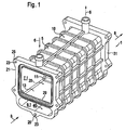
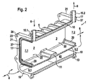
- Fig. 1 and Fig. 2 show a heat exchanger housing 1 for the arrangement of the flow-through of exhaust gas flow passages of a high-temperature heat exchanger 2, not shown, and the flow-through of exhaust gas flow channels of a non-illustrated low-temperature heat exchanger 3 respectively in a first part 20 and a second part 30 of a chamber of the housing body 10 of the heat exchanger housing.
- This housing for the parts 20, 30 of the chamber is marked by a cross-sectionally trapezoidal and integrally formed with the housing body 10 base 11, wherein the trapezoidal design of the base 11 for self-aligning the high-temperature heat exchanger 2 and the low-temperature heat exchanger 3 in the parts 20, 30 of Chamber serves.
- the heat exchanger housing 1 also has a bypass channel 40, which is separated by a partition 13 from the parts 20, 30 of the chamber.
- the base 11 is formed integrally with the partition wall 13.
- the bypass channel 40 designed for the passage of exhaust gas and the parts 20, 30 of the chamber are formed integrally with the housing body 10.
- the parts 20, 30 of the chamber and the bypass channel 40 are bounded by a wall 5 of the housing body 10, wherein in a section transverse to the elongated extension of the housing 1, the wall 5 and the partition 13 assume an octagonal shape, each one Forming the input-side and output-side first opening 7.1 or 7.2 to the first part 20 and second part 30 of the chamber and an input-side second opening 9.1 and 9.2 to the bypass channel 40.
- the heat exchanger housing 1 is thus designed to flow through with exhaust gas 8 through the openings 7.1, 7.2 and / or 9.1, 9.2.
- integrally formed with the housing body 10 is an inlet-side second fluid port 15.1 and an outlet-side second fluid port 15.2 for supplying or discharging a coolant 6, each in the form of a connecting piece.
- FIG. 1 and Fig. 2 described embodiment of a heat exchanger housing an inlet border 17 of a first part 20 and a second part 30 of the chamber and an inlet border 19 of the bypass channel 40 and a second fluid port 15.1 and 15.2 as a common connecting part 21 and 31 of the housing body 10.
- the connecting part 21 and the output-side connecting part 31 are each in the form of an eight-shaped flange, which are provided on the corner with a part 20, 30 of the chamber with eyes 25 having fastening openings 23, on the outside of the housing a box cover designed as a diffuser for the supply or delivery To install exhaust gas outlet.
- Another provided with a mounting opening 23 eye 25 on the connecting part 21 and 31 is located centrally below the bypass channel 40.
- connecting part 21, 31 is provided with a bead 27 for receiving a seal in order to each seal a diffuser on the connecting part 21, 31 and thus to allow a seal carried in the parts 20, 30 to the exhaust gas.
- a block closure element in the form of a bottom can be fixed in a manner not shown.
- Such a bottom is provided with a plurality of passage openings for receiving the flow channels of the high-temperature heat exchanger 2 and the low-temperature heat exchanger 3.
- Additional bottoms of the high-temperature heat exchanger 2 or low-temperature heat exchanger 3 can be arranged on the base 11.
- a housing body 1 is provided, with a chamber designed for the flow of coolant and for receiving a number of flow channels through which exhaust gas can flow as well as a bypass duct 40 designed for flow with exhaust gas, both in one piece are formed with the housing body 10.
- the housing body 10 may be integrally formed according to the embodiment described above with connecting parts 21, 31, the corresponding edges 17, 19 of the chamber and the bypass channel 40 and connecting pieces 15.1, 15.2 combine for the coolant and further advantageous for housing a diffuser on the outside of the housing and a bottom housing inside are formed.
- the heat exchanger housing in a manufacturing step, in this case in the context of a cast aluminum, can be produced.
- the heat exchanger housing may also be manufactured as a steel investment casting or as a plastic injection molded part.
Abstract
Description
Die Erfindung betrifft ein Wärmetauscher-Gehäuse für wenigstens einen Wärmetauscher zum Wärmetausch zwischen einem ersten Fluid und einem zweiten Fluid. Weiter betrifft die Erfindung einen Wärmetauscher oder eine Baueinheit mit einem oder mehreren Wärmetauschern zum Wärmetausch zwischen einem ersten Fluid und einem zweiten Fluid. Die Erfindung betrifft auch ein Abgasrückführsystem, ein Ladeluftzuführsystern und eine Verwendung des Wärmetauschers oder der Baueinheit.The invention relates to a heat exchanger housing for at least one heat exchanger for heat exchange between a first fluid and a second fluid. Furthermore, the invention relates to a heat exchanger or a structural unit with one or more heat exchangers for heat exchange between a first fluid and a second fluid. The invention also relates to an exhaust gas recirculation system, a charge air supply system and a use of the heat exchanger or the structural unit.
Eine Abgasrückführung oder Ladeluftzuführung, insbesondere mit gekühltem Abgas und/oder Ladeluft, wird in heutigen Fahrzeugen aufgrund gesetzlicher Bestimmungen eingesetzt, um die Partikel- und Schadstoffe, insbesondere Stickoxidemissionen, zu senken. Einerseits steigen dabei die Anforderungen an die Abgasreinhaltung und die zu bewältigenden Abgasmassenströme, andererseits sind solche Systeme und insbesondere die dazu notwendigen Wärmetauscherentwicklungen stark kostengetrieben.Exhaust gas recirculation or charge air supply, in particular with cooled exhaust gas and / or charge air, is used in current vehicles due to legal provisions in order to reduce particulate matter and pollutants, in particular nitrogen oxide emissions. On the one hand, the requirements for the exhaust gas pollution control and the exhaust gas mass flows to be managed increase, on the other hand, such systems and in particular the necessary heat exchanger developments are highly cost-driven.
Ein Wärmetauscher dient grundsätzlich zum Wärmetausch zwischen einem ersten Fluid, insbesondere einem Abgas im Falle eines Abgaskühlers oder einer Ladeluft im Falle eines Ladeluftkühlers, und einem zweiten Fluid, insbesondere einem Kühlmittel, beispielsweise einem wasserbasierten Kühlmittel oder einem sonstigen flüssigen oder gasförmigen Kühlmittel. Insbesondere Abgaskühler werden gegebenenfalls mit einem Bypass-Rohr ausgebaut, um die Betriebstemperatur an einer Brennkraftmaschine schneller zu erreichen. Ein Bypass-Kanal kann dazu beispielsweise über eine Klappe zugemacht werden sobald die Betriebstemperatur an der Brennkraftmaschine erreicht ist und ein Wärmetauscher zur Aufnahme des Kühlbetriebs vorgesehen ist. So ist beispielsweise in
An dieser Stelle setzt die Erfindung an, deren Aufgabe es ist, eine Vorrichtung, insbesondere ein Wärmetauschergehäuse und einen Wärmetauscher, anzugeben, bei der die Integration eines Bypass-Kanal einfacher und kosteneffektiver realisiert ist.At this point, the invention begins, the object of which is to provide a device, in particular a heat exchanger housing and a heat exchanger, in which the integration of a bypass channel is realized in a simpler and more cost-effective manner.
Betreffend die Vorrichtung wird die Aufgabe durch die Erfindung mit einem Wärmetauschergehäuse der eingangs genannten Art gelöst, das erfindungsgemäß einen Gehäusekörper aufweist mit einer zur Durchströmung von dem zweiten Fluid und zur Aufnahme einer Anzahl von dem ersten Fluid durchströmbarer Strömungskanäle ausgelegten Kammer; einem zur Durchströmung von dem ersten Fluid ausgelegten Bypass-Kanal; wobei die Kammer und der Bypass-Kanal einstückig mit dem Gehäusekörper gebildet sind. Mit anderen Worten, das Konzept der Erfindung sieht vor, dass der Bypass-Kanal im Wärmetauschergehäuse einstückig integriert ist. Dies hat den Vorteil, dass der Bypass-Kanal und das Gehäuse auf besonders einfache und kostensparende Weise in einem einzigen Herstellungsschritt herstellbar sind. Dadurch entfallen die Kostenaufwand erzeugenden und zum Teil aufwändigen separaten Herstellungsschritte für ein Bypass-Rohr bzw, die Kassetierung eines Bypass-Rohres in einem Gehäuse.With regard to the device, the object is achieved by the invention with a heat exchanger housing of the type mentioned, which according to the invention comprises a housing body with a flow-through from the second fluid and for receiving a number of the first fluid flow-through flow channels designed chamber; a bypass channel designed to flow through the first fluid; wherein the chamber and the bypass channel are formed integrally with the housing body. In other words, the concept of the invention provides that the bypass channel is integrally integrated in the heat exchanger housing. This has the advantage that the bypass channel and the housing can be produced in a particularly simple and cost-saving manner in a single production step. This eliminates the cost-generating and sometimes expensive separate manufacturing steps for a bypass pipe or, the Kassetierung a bypass pipe in a housing.
Es hat sich gezeigt, dass eine Kosteneinsparung bereits aufgrund der Materialkosten umso höher ist, je länger eine längliche Erstreckung des Bypass-Kanals bzw. des Wärmetauschergehäuses ist.It has been shown that the longer a longitudinal extension of the bypass channel or of the heat exchanger housing, the higher the cost savings due to the material costs.
Betreffend die Vorrichtung wird die Aufgabe durch die Erfindung auch mittels einem Wärmetauscher oder einer Baueinheit mit einem oder mehreren Wärmetauschern der eingangs genannten Art gelöst, der erfindungsgemäß aufweist: einen Block zur voneinander getrennten und wärmetauschenden Führung des ersten und zweiten Fluids, welcher Block ein Wärmetauschergehäuse mit integriertem Bypass-Kanal gemäß dem Konzept der Erfindung aufweist und eine in dem Wärmetauschergehäuse aufgenommene Anzahl von dem ersten Fluid durchströmbarer Strömungskanäle aufweist.Regarding the device, the object is achieved by the invention by means of a heat exchanger or a structural unit with one or more heat exchangers of the type mentioned, which comprises: a block for separate and heat exchanging guidance of the first and second fluid, which block a heat exchanger housing with integrated bypass channel according to the concept of the invention and has a recorded in the heat exchanger housing number of the first fluid permeable flow channels.
Vorzugsweise ist das erste Fluid als ein Abgas und/oder eine Ladeluft gebildet. Ein Wärmetauscher kann vorzugsweise als ein Abgaswärmetauscher und/oder Ladeluftwärmetauscher gebildet sein. Vorzugsweise ist das zweite Fluid in Form eines Kühlmittels, beispielsweise eines wasserbasierten Kühlmittels oder anderen flüssigen Kühlmittels gebildet. Geeignet kann auch ein gasförmiges Kühlmittel sein.Preferably, the first fluid is formed as an exhaust gas and / or a charge air. A heat exchanger may preferably be formed as an exhaust gas heat exchanger and / or charge air heat exchanger. Preferably, the second fluid is formed in the form of a coolant, for example a water-based coolant or other liquid coolant. Also suitable may be a gaseous coolant.
Das Konzept der Erfindung führt auch auf ein Abgasrückführsystem für eine Brennkraftmaschine, aufweisend eine Abgasrückführung, einen Kompressor und einen Wärmetauscher der vorgenannten Art in Form eines Abgaswärmetauschers, insbesondere eines Abgaskühlers.The concept of the invention also leads to an exhaust gas recirculation system for an internal combustion engine, comprising an exhaust gas recirculation, a compressor and a heat exchanger of the aforementioned type in the form of an exhaust gas heat exchanger, in particular an exhaust gas cooler.
Das Konzept der Erfindung führt auch auf ein Ladeluftzuführsystem für eine Brennkraftmaschine, aufweisend eine Ladeluftansaugung, einen Luftfilter, einen Kompressor und einen Wärmetauscher der vorgenannten Art in Form eines Ladeluftwärmetauschers, insbesondere Ladeluftkühlers.The concept of the invention also leads to a charge air supply system for an internal combustion engine, comprising a charge air intake, an air filter, a compressor and a heat exchanger of the aforementioned type in the form of a charge air heat exchanger, in particular intercooler.
Weiter führt die Erfindung auf eine Verwendung des Wärmetauschers oder der Baueinheit der vorgenannten Art für eine Brennkraftmaschine, insbesondere einen Dieselmotor oder Ottomotor eines Kraftfahrzeugs.Further, the invention leads to a use of the heat exchanger or the assembly of the aforementioned type for an internal combustion engine, in particular a diesel engine or gasoline engine of a motor vehicle.
Vorteilhafte Weiterbildungen der Erfindung sind den Unteransprüchen zu entnehmen und geben im Einzelnen vorteilhafte Möglichkeiten an, das oben erläuterte Konzept im Rahmen der Aufgabenstellung sowie hinsichtlich weiterer Vorteile zu realisieren.Advantageous developments of the invention can be found in the dependent claims and specify in particular advantageous ways to realize the above-described concept within the scope of the problem and with regard to further advantages.
Vorzugsweise ist der Bypass-Kanal der einzige Bypass-Kanal und/oder erstreckt sich entlang der gesamten Länge einer länglichen Erstreckung des Gehäusekörpers. Insbesondere kann der Bypass-Kanal dazu praktisch die gleiche Länge wie die Kammer aufweisen. Der Bypass-Kanal kann im Querschnitt einer Anwendung entsprechend ausgebildet sein, insbesondere rechteckig, oval oder halboval ausgebildet sein.Preferably, the bypass channel is the only bypass channel and / or extends along the entire length of an elongated extension of the housing body. In particular, the bypass channel can have practically the same length as the chamber. The bypass channel can be designed correspondingly in cross-section of an application, in particular rectangular, oval or semi-oval.
Vorzugsweise ist die Kammer zur Aufnahme der Strömungskanäle zweier Wärmetauscher, insbesondere eines Hochtemperaturwärmetauschers und eines Niedertemperaturwärmetauschers, ausgebildet. Im Rahmen einer besonders bevorzugten Weiterbildung ist dazu an einer Innenseite des Gehäusekörpers ein Sockel einstückig mit dem Gehäusekörper gebildet. Vorzugsweise ist der Sockel quer zur länglichen Erstreckung des Gehäusekörpers angeordnet. Vorteilhaft weist er einen trapezförmigen Querschnitt auf. Somit können jeweils die Strömungskanäle eines ersten Wärmetauschers und eines zweiten Wärmetauschers in einen durch den Sockel markierten ersten Teil bzw. zweiten Teil der Kammer angeordnet werden. Ein querschnittlich trapezförmiger Sockel erlaubt dabei eine praktisch selbstjustierende Anordnung der Strömungskanäle.Preferably, the chamber for receiving the flow channels of two heat exchangers, in particular a high-temperature heat exchanger and a low-temperature heat exchanger is formed. Within the scope of a particularly preferred development, this is done on an inner side of the housing body a socket formed integrally with the housing body. Preferably, the base is arranged transversely to the elongate extent of the housing body. Advantageously, it has a trapezoidal cross-section. Thus, in each case the flow channels of a first heat exchanger and a second heat exchanger can be arranged in a marked by the base first part or second part of the chamber. A cross-sectionally trapezoidal base allows a practically self-aligning arrangement of the flow channels.
Gemäß einer Weiterbildung der Erfindung weist das Wärmetauschergehäuse wenigstens ein Anschlussteil, vorzugsweise ein eingangsseitiges und ein ausgangsseitiges Anschlussteil, zur Anbindung wenigstens eines ersten Fluidanschlusses für das erste Fluid auf. Insbesondere ist das Anschlussteil einstückig mit dem Gehäusekörper gebildet. Eine Weiterbildung des Wärmetauschers sieht vorteilhaft vor, dass ein erster Fluidanschluss mit den Strömungskanälen strömungsverbunden an dem Anschlussteil des Gehäusekörpers angeordnet ist. Der erste Fluidanschluss kann beispielsweise als ein Kasten und/oder ein Kastendeckel gebildet sein, vorzugsweise in Form eines Diffusors. Ein eintrittsseitiger Fluidanschluss kann als ein Eintrittsdiffusor und/oder austrittsseitiger Fluidanschluss als ein Austrittsdiffusor gebildet sein. Darüber hinaus hat es sich als vorteilhaft erwiesen, eine Bypass-Regeleinrichtung beim Wärmetauscher zur Einstellung der Abgasführung durch den wenigstens einen Wärmetauscher vorzusehen. Die Regeleinrichtung kann in besonders vorteilhafter Weise im Fluidanschluss integriert sein. Beispielsweise kann eine Bypass-Klappe in einem Diffusor integriert sein. Andere mögliche vorteilhafte Regeleinrichtungen können zusätzlich oder alternativ in Form einer Ventileinrichtung, beispielsweise eines regelbaren Ventils, gebildet sein.According to one embodiment of the invention, the heat exchanger housing has at least one connection part, preferably an input-side and an output-side connection part, for connecting at least one first fluid connection for the first fluid. In particular, the connection part is formed integrally with the housing body. A development of the heat exchanger advantageously provides that a first fluid connection with the flow channels is arranged fluidly connected to the connection part of the housing body. The first fluid connection can be formed, for example, as a box and / or a box lid, preferably in the form of a diffuser. An entrance-side fluid port may be formed as an entrance diffuser and / or exit-side fluid port as an exit diffuser. Moreover, it has proved to be advantageous to provide a bypass control device in the heat exchanger for adjusting the exhaust gas passage through the at least one heat exchanger. The control device can be integrated in a particularly advantageous manner in the fluid connection. For example, a bypass flap may be integrated in a diffuser. Other possible advantageous control devices may additionally or alternatively be in the form of a valve device, for example a controllable valve.
Das Anschlussteil des Wärmetauschergehäuses kann in einer besonders bevorzugten Weiterbildung ausgebildet sein, um - einerseits - insbesondere gehäuseinnenseitig, ein Blockabschlusselement zur Trennung der Kammer und eines ersten Fluidanschlusses für das erste Fluid am Anschlussteil des Gehäusekörpers anzuordnen und/oder - anderenseits - insbesondere gehäuseaußenraumseitig, den Fluidanschluss am Anschlussteil anzuordnen. Das Blockabschlusselement, beispielsweise in Form eines Bodens, ist dazu vorzugsweise mit einer oder mit mehreren Durchgangsöffnungen für die Strömungskanäle versehen.The connection part of the heat exchanger housing may be formed in a particularly preferred development to - on the one hand - in particular Housing inside, a block terminating element for separating the chamber and a first fluid port for the first fluid to be arranged on the connection part of the housing body and / or - on the other hand - in particular housing outside space side, to arrange the fluid connection to the connection part. The block closure element, for example in the form of a bottom, is preferably provided with one or more passage openings for the flow channels.
Im Rahmen einer besonders bevorzugten Weiterbildung ist dazu vorgesehen, das Anschlussteil als einen Flansch auszubilden. Vorzugsweise weist der Flansch gehäuseinnenseitig und/oder gehäuseaußenseitig, eine Sicke auf, welche vorzugsweise zur Aufnahme einer Dichtung dient. Es hat sich gezeigt, dass dadurch eine besonders vorteilhafte und fluiddichte Trennung eines ersten Fluids in den Strömungskanälen bzw. einem ersten Fluidanschluss und eines zweiten Fluids in der Kammer möglich ist.In the context of a particularly preferred development, it is provided to form the connection part as a flange. Preferably, the flange inside the housing and / or outside the housing, a bead, which preferably serves to receive a seal. It has been found that thereby a particularly advantageous and fluid-tight separation of a first fluid in the flow channels or a first fluid port and a second fluid in the chamber is possible.
Vorzugsweise weist das Wärmetauschergehäuse auch einen zweiten Fluidanschluss für das zweite Fluid auf, wobei der wenigstens eine zweite Fluidanschluss, beispielsweise ein fluideinlassender und ein fluidauslassender Anschluss, einstückig mit dem Gehäusekörper gebildet ist. In besonders vorteilhafter Weise ist ein zweiter Fluidanschluss in Form eines Stutzens gebildet. Dies hat sich als besonders geeignet zur Anbindung einer Leitung für das zweite Fluid erwiesen.Preferably, the heat exchanger housing also has a second fluid connection for the second fluid, wherein the at least one second fluid connection, for example a fluid inlet and a fluid outlet connection, is formed integrally with the housing body. In a particularly advantageous manner, a second fluid connection is formed in the form of a nozzle. This has proved to be particularly suitable for connecting a conduit for the second fluid.
In einer die vorgenannten Weiterbildungen kombinierenden Form ist das Wärmetauschergehäuse besonders vorteilhaft mit einem Anschlussteil zur Anbindung wenigstens des ersten Fluidanschlusses für das erste Fluid und einem zweiten Fluidanschluss für das zweite Fluid versehen, wobei die ersten und zweiten Fluidanschlüsse einstückig mit dem Gehäuse gebildet sind.In a form combining the aforementioned further developments, the heat exchanger housing is particularly advantageously provided with a connection part for connecting at least the first fluid connection for the first fluid and a second fluid connection for the second fluid, wherein the first and second fluid connections are formed integrally with the housing.
Im Rahmen einer ganz besonders bevorzugten Weiterbildung ist vorgesehen, dass ein Anschlussteil eine Einlassumrandung für das erste Fluid aufweist und diese Einlassumrandung und eine weitere Einlassumrandung des Bypass-Kanals an gleicher Stelle einer länglichen Erstreckung des Gehäusekörpers gebildet sind. Insbesondere kann dazu die Einlassumrandung im Anschlussteil als ein gemeinsames Teil des Gehäusekörpers gebildet sein. Mit anderen Worten, kann ein Anschlussteil - beispielsweise in Form eines achtförmigen Flansches - eine erste Öffnung zu der Kammer aufweisen und eine zweite Öffnung zum Bypass-Kanal aufweisen. Zusätzlich oder alternativ können das Anschlussteil, ebenfalls unter Kombination der vorgenannten Weiterbildungen, und ein zweiter Fluidanschluss an gleicher Stelle einer länglichen Erstreckung des Gehäusekörpers gebildet sein. Vorzugsweise ist dazu der zweite Fluidanschluss am Anschlussteil als ein gemeinsames Teil des Gehäusekörpers gebildet. Dies hat den Vorteil, dass ein zweites Fluid - insbesondere ein Kühlmittel - und ein erstes Fluid - beispielsweise ein Abgas und/oder eine Ladeluft - praktisch an gleicher Stelle der länglichen Erstreckung des Wärmetauschergehäuses zugeführt und abgeführt werden und somit über einen besonders langen Weg entlang der länglichen Erstreckung nebeneinander geführt werden - dies führt zu einer besonders vorteilhaft optimierten Kühlleistung eines Wärmetauschers.Within the scope of a particularly preferred development, it is provided that a connection part has an inlet border for the first fluid and this inlet border and a further inlet border of the bypass channel are formed at the same point of an elongated extent of the housing body. In particular, for this purpose, the inlet border in the connection part can be formed as a common part of the housing body. In other words, a connection part - for example in the form of an eight-shaped flange - may have a first opening to the chamber and a second opening to the bypass channel. Additionally or alternatively, the connection part may also be formed at the same point of an elongated extension of the housing body, likewise with a combination of the aforementioned further developments, and a second fluid connection. For this purpose, the second fluid connection to the connection part is preferably formed as a common part of the housing body. This has the advantage that a second fluid-in particular a coolant-and a first fluid-for example, an exhaust gas and / or a charge air-are supplied and discharged practically at the same point to the elongate extent of the heat exchanger housing and thus over a particularly long distance along the elongated extension are performed side by side - this leads to a particularly advantageous optimized cooling performance of a heat exchanger.
Vorzugsweise ist das Wärmetauschergehäuse mit einer Anzahl von einstückig mit dem Gehäusekörper gebildeten Kühlrippen versehen. Kühlrippen können insbesondere umfänglich und/oder entlang einer länglichen Erstreckung des Gehäusekörpers verlaufen. Je nach Bedarf können die Kühlrippen der Einfachheit halber am Bypass-Kanal und am Kammerteil des Gehäuses durchgehend verlaufen. Grundsätzlich können die Kühlrippen je nach Bedarf und der abzuführenden Wärmemenge ausgelegt sein bzw. zusätzlich oder alternativ als Verstärkungsrippen ausgelegt sein.Preferably, the heat exchanger housing is provided with a number of cooling fins formed integrally with the housing body. Cooling ribs may in particular extend circumferentially and / or along an elongated extent of the housing body. Depending on requirements, the cooling fins can for simplicity run through the bypass channel and the chamber part of the housing through. In principle, the cooling fins can be designed according to requirements and the amount of heat to be dissipated or additionally or alternatively designed as reinforcing ribs.
Es hat sich gezeigt, dass die Ausführung des Wärmetauschergehäuses als ein Aluminiumgussteil besonders bevorzugt ist. Grundsätzlich kann das Wärmetauschergehäuse auch als ein Stahl- oder als ein Kunststoffteil ausgebildet sein - vorzugsweise als Feinguss- oder Spritzgussteil.It has been found that the design of the heat exchanger housing as an aluminum casting is particularly preferred. In principle, the heat exchanger housing can also be designed as a steel part or as a plastic part - preferably as a precision casting or injection molded part.
Ausführungsbeispiele der Erfindung werden nun nachfolgend anhand der beschrieben. Diese soll die Ausführungsbeispiele nicht notwendigerweise maßstäblich darstellen, vielmehr ist die Zeichnung, wo zur Erläuterung dienlich, in schematisierter und/oder leicht verzerrter Form ausgeführt. Im Hinblick auf Ergänzungen der aus der Zeichnung unmittelbar erkennbaren Lehren wird auf den einschlägigen Stand der Technik verwiesen. Dabei ist zu berücksichtigen, dass vielfältige Modifikationen und Änderungen betreffend die Form und das Detail einer Ausführungsform vorgenommen werden können, ohne von der allgemeinen Idee der Erfindung abzuweichen. Die in der Beschreibung, in der Zeichnung sowie in den Ansprüchen offenbarten Merkmale der Erfindung können sowohl einzeln als auch in beliebiger Kombination für die Weiterbildung der Erfindung wesentlich sein. Zudem fallen in den Rahmen der Erfindung alle Kombinationen aus zumindest zwei der in der Beschreibung, der Zeichnung und/oder den Ansprüchen offenbarten Merkmale. Die allgemeine Idee der Erfindung ist nicht beschränkt auf die exakte Form oder das Detail der im folgenden gezeigten und beschriebenen bevorzugten Ausführungsform oder beschränkt auf einen Gegenstand, der eingeschränkt wäre im Vergleich zu dem in den Ansprüchen beanspruchten Gegenstand. Bei angegebenen Bemessungsbereichen sollen auch innerhalb der genannten Grenzen liegende Werte als Grenzwerte offenbart und beliebig einsetzbar und beanspruchbar sein.Embodiments of the invention will now be described below with reference to FIG. This is not necessarily to scale the embodiments, but the drawing, where appropriate for explanation, executed in a schematized and / or slightly distorted form. With regard to additions to the teachings directly recognizable from the drawing reference is made to the relevant prior art. It should be noted that various modifications and changes may be made in the form and detail of an embodiment without departing from the general idea of the invention. The disclosed in the description, in the drawing and in the claims features of the invention may be essential both individually and in any combination for the development of the invention. In addition, all combinations of at least two of the features disclosed in the description, the drawings and / or the claims fall within the scope of the invention. The general idea of the invention is not limited to the exact form or detail of the preferred embodiment shown and described below or limited to an article which would be limited in comparison to the subject matter claimed in the claims. For the given design ranges, values within the stated limits should also be disclosed as limit values and be arbitrarily usable and claimable.
Vorteilhaft ist, dass ein Blockabschlusselement zur Trennung der Kammer und eines ersten Fluidanschlusses für das erste Fluid, an einem Anschlussteil (21, 31) des Gehäusekörpers (10) angeordnet ist, wobei das Blockabschlusselement, insbesondere ein Boden, mit einer oder mit mehreren Durchgangsöffnungen für die Strömungskanäle versehen ist.It is advantageous that a block closure element for separating the chamber and a first fluid connection for the first fluid is arranged on a connection part (21, 31) of the housing body (10), wherein the block closure element, in particular, a floor is provided with one or more passage openings for the flow channels.
Vorteilhaft ist ein Wärmetauscher oder Baueinheit, aufweisend eine Bypass-Regeleinrichtung zur Einstellung der Abgasführung durch den wenigstens einen Wärmetauscher, insbesondere eine Ventileinrichtung und/oder Bypassklappe, und/oder ein Ventil, insbesondere ein Abgasrückführventil.Advantageously, a heat exchanger or structural unit, comprising a bypass control device for adjusting the exhaust gas flow through the at least one heat exchanger, in particular a valve device and / or bypass valve, and / or a valve, in particular an exhaust gas recirculation valve.
Vorteilhaft ist, dass eine Regeleinrichtung im ersten, vorzugsweise eingangsseitigen, Fluidanschluss integriert ist, insbesondere eine Bypass-Klappe in einem Diffusor integriert ist.It is advantageous that a control device is integrated in the first, preferably input-side, fluid connection, in particular a bypass flap is integrated in a diffuser.
Vorteilhaft ist ein Wärmetauscher oder Baueinheit, aufweisend einen Hochtemperatur-Wärmetauscher und/oder Niedertemperatur-Wärmetauscher, wobei der Niedertemperatur-Wärmetauscher stromabwärts vom Hochtemperatur-Wärmetauscher angeordnet ist.Advantageously, a heat exchanger or structural unit, comprising a high-temperature heat exchanger and / or low-temperature heat exchanger, wherein the low-temperature heat exchanger is arranged downstream of the high-temperature heat exchanger.
Vorteilhaft ist ein Abgasrückführsystem für eine Brennkraftmaschine, aufweisend eine Abgasrückführung, einen Kompressor und gekennzeichnet durch einen Wärmetauscher oder Baueinheit in Form eines Abgas-Wärmetauschers, insbesondere -Kühlers.Advantageously, an exhaust gas recirculation system for an internal combustion engine, comprising an exhaust gas recirculation, a compressor and characterized by a heat exchanger or structural unit in the form of an exhaust gas heat exchanger, in particular -Kühlers.
Vorteilhaft ist die Verwendung des Wärmetauschers oder der Baueinheit, für eine Brennkraftmaschine, insbesondere einen Diesel-Motor oder Otto-Motor, eines Kraftfahrzeugs.Advantageously, the use of the heat exchanger or the assembly, for an internal combustion engine, in particular a diesel engine or gasoline engine, a motor vehicle.
Im Einzelnen zeigt die Zeichnung in:
- Fig. 1:
- eine dreidimensionale perspektivische Ansicht einer besonders bevorzugten Ausführungsform des Wärmetauschergehäuses;
- Fig.2:
- eine dreidimensionale perspektivische Teilschnittansicht des Wärmetauschergehäuses von
Fig. 1 .
- Fig. 1:
- a three-dimensional perspective view of a particularly preferred embodiment of the heat exchanger housing;
- Figure 2:
- a three-dimensional perspective partial sectional view of the heat exchanger housing of
Fig. 1 ,
Insgesamt ist der zur Durchströmung von Abgas ausgelegte Bypass-Kanal 40 und die Teile 20, 30 der Kammer einstückig mit dem Gehäusekörper 10 gebildet. Außenseitig werden die Teile 20, 30 der Kammer und der Bypass-Kanal 40 von einer Wandung 5 des Gehäusekörpers 10 begrenzt, wobei in einem Schnitt quer zur länglichen Erstreckung des Gehäuses 1 die Wandung 5 und die Trennwand 13 eine achtförmige Form annehmen, die eine jeweils eingangsseitige und ausgangsseitige erste Öffnung 7.1 bzw. 7.2 zum ersten Teil 20 bzw. zweiten Teil 30 der Kammer sowie eine eingangsseitige zweite Öffnung 9.1 und 9.2 zum Bypass-Kanal 40 ausbilden.Overall, the
Das Wärmetauschergehäuse 1 ist damit zur Durchströmung mit Abgas 8 durch die Öffnungen 7.1, 7.2 und/oder 9.1, 9.2 ausgelegt.The heat exchanger housing 1 is thus designed to flow through with exhaust gas 8 through the openings 7.1, 7.2 and / or 9.1, 9.2.
Darüber hinaus ist einstückig mit dem Gehäusekörper 10 ein einlassseitiger zweiter Fluidanschluss 15.1 sowie ein auslassseitiger zweiter Fluidanschluss 15.2 zur Zuführung bzw. Abführung eines Kühlmittels 6 jeweils in Form eines Stutzens gebildet.In addition, integrally formed with the
In besonders vorteilhafter Weise verwirklicht die in den
Darüber hinaus ist das Anschlussteil 21, 31 mit einer Sicke 27 zur Aufnahme einer Dichtung versehen, um jeweils einen Diffusor am Anschlussteil 21, 31 dichtend anzuordnen und damit eine Abdichtung des in den Teilen 20, 30 geführten Kühlmittels gegenüber dem Abgas zu ermöglichen.In addition, the connecting
An einer Innenseite 29 des Anschlussteils 21, 31 ist in nicht näher dargestellter Weise ein Blockabschlusselement in Form eines Bodens festlegbar. Ein solcher Boden ist mit mehreren Durchgangsöffnungen zur Aufnahme der Strömungskanäle des Hochtemperaturwärmetauschers 2 bzw. des Niedertemperaturwärmetauschers 3 versehen. In nicht näher dargestellter Weise können zusätzliche Böden jeweils des Hochtemperaturwärmetauschers 2 bzw. Niedertemperaturwärmetauschers 3 am Sockel 11 angeordnet werden.On an
Damit ist im Rahmen der zuvor beschriebenen Ausführungsform eines Wärmetauschergehäuses 10 ein Gehäusekörper 1 vorgesehen, mit einer zur Beströmung von Kühlmittel und zur Aufnahme einer Anzahl von mit Abgas durchströmbaren Strömungskanälen ausgelegten Kammer als auch ein zur Strömung mit Abgas ausgelegter Bypass-Kanal 40, die beide einstückig mit dem Gehäusekörper 10 gebildet sind. Zudem kann der Gehäusekörper 10 gemäß der zuvor beschriebenen Ausführungsform in besonders vorteilhafter Weise mit Anschlussteilen 21, 31 einstückig gebildet sein, die entsprechende Umrandungen 17, 19 der Kammer und des Bypass-Kanals 40 als auch Anschlussstutzen 15.1, 15.2 für das Kühlmittel vereinen und weiter vorteilhaft zur Anordnung eines Diffusors gehäuseaußenseitig und eines Bodens gehäuseinnenseitig ausgebildet sind. Dies ermöglicht nicht nur eine besonders kosteneffektive, sondern auch besonders einfache Herstellung eines Wärmetauschers, da das Wärmetauschergehäuse in einem Herstellungsschritt, vorliegend im Rahmen eines Aluminiumgusses, herstellbar ist. In einer Abwandlung der vorliegenden Ausführungsform kann das Wärmetauschergehäuse auch als ein Stahlfeingussteil oder als ein Kunststoffspritzgussteil hergestellt werden.Thus, in the context of the above-described embodiment of a
Claims (15)
dadurch gekennzeichnet, dass
ein Anschlussteil (21, 31) als ein Flansch, vorzugsweise als ein Flansch mit Sicke (27), gebildet ist, vorzugsweise mit einer Sicke (27) zur Aufnahme einer Dichtung.Heat exchanger housing (1) according to claim 1 or 2;
characterized in that
a connecting part (21, 31) is formed as a flange, preferably as a flange with a bead (27), preferably with a bead (27) for receiving a seal.
gekennzeichnet durch
jeweils ein separates in Bezug auf das erste Fluid eintrittsseitiges (21) und austrittsseitiges (31) Anschlussteil.Heat exchanger housing (1) according to one of claims 1 to 3,
marked by
in each case a separate inlet-side (21) and outlet-side (31) connection part with respect to the first fluid.
dadurch gekennzeichnet, dass
ein Anschlussteil (21, 31) eine Einlassumrandung (17) für das erste Fluid aufweist und diese Einlassumrandung (17) und eine Einlassumrandung des Bypass-Kanals (40) an gleicher Stelle einer länglichen Erstreckung des Gehäusekörpers (10) gebildet sind, insbesondere die Einlassumrandungen (17, 19) am Anschlussteil (21,31) als ein gemeinsames Teil des Gehäusekörpers (10) gebildet ist.Heat exchanger housing according to one of claims 1 to 5,
characterized in that
a connection part (21, 31) has an inlet border (17) for the first fluid, and this inlet border (17) and an inlet border of the bypass channel (40) are formed at the same location of an elongated extension of the housing body (10), in particular the inlet borders (17, 19) is formed on the connecting part (21, 31) as a common part of the housing body (10).
dadurch gekennzeichnet, dass
ein Anschlussteil (21, 31) und ein zweiter Fluidanschluss (15.1, 15.2) an gleicher Stelle einer länglichen Erstreckung des Gehäusekörpers (10) gebildet sind, insbesondere der zweite Fluidanschluss (15.1, 15.2) am Anschlussteil (21, 31) als ein gemeinsames Teil des Gehäusekörpers (10) gebildet ist.Heat exchanger housing (1) according to one of claims 1 to 6,
characterized in that
a connection part (21, 31) and a second fluid connection (15.1, 15.2) are formed at the same location of an elongated extension of the housing body (10), in particular the second fluid connection (15.1, 15.2) on the connection part (21, 31) as a common part the housing body (10) is formed.
dadurch gekennzeichnet, dass
an einer Innenseite (29), insbesondere quer zu einer länglichen Erstreckung des Gehäusekörpers (10), ein Sockel (11), insbesondere ein querschnittlich trapezförmiger Sockel (11), einstückig mit dem Gehäusekörper (10) gebildet ist.Heat exchanger housing (1) according to one of claims 1 to 7,
characterized in that
on an inner side (29), in particular transversely to an elongated extension of the housing body (10), a base (11), in particular a cross-sectionally trapezoidal base (11), is integrally formed with the housing body (10).
dadurch gekennzeichnet, dass
Kühlrippen, insbesondere umfänglich und/oder entlang einer länglichen Erstreckung des Gehäusekörpers (10) verlaufende Kühlrippen, einstückig mit dem Gehäusekörper (10) gebildet sind.Heat exchanger housing (1) according to one of claims 1 to 8,
characterized in that
Cooling ribs, in particular circumferentially and / or along an elongated extent of the housing body (10) extending cooling fins, are integrally formed with the housing body (10).
dadurch gekennzeichnet, dass
ein Bypass-Kanal-Querschnitt rechteckig, oval oder halboval ausgebildet ist.Heat exchanger housing (1) according to one of claims 1 to 10,
characterized in that
a bypass channel cross section is rectangular, oval or semi-oval.
dadurch gekennzeichnet, dass,
wenigstens ein erster Fluidanschluss, insbesondere ein Kasten und/oder ein Kastendeckel, welcher mit den Strömungskanälen strömungsverbunden ist, an einem Anschlussteil (21, 31) des Gehäusekörpers(10) angeordnet ist.Heat exchanger or assembly according to claim 12,
characterized in that
at least one first fluid connection, in particular a box and / or a box lid, which is flow-connected to the flow channels, is arranged on a connection part (21, 31) of the housing body (10).
dadurch gekennzeichnet, dass
der Fluidanschluss in Form eines Diffusors, insbesondere eines Eintrittsdiffusors und/oder Austrittsdiffusors, gebildet ist.Heat exchanger or assembly according to claim 12 or 13,
characterized in that
the fluid connection is formed in the form of a diffuser, in particular an inlet diffuser and / or outlet diffuser.
gekennzeichnet durch
einen Wärmetauscher oder Baueinheit nach einem der Ansprüche 12 bis 18 in Form eines Ladeluft-Wärmetauschers, insbesondere -Kühlers.Charge air supply system for an internal combustion engine, comprising a charge air intake, an air filter, a compressor and
marked by
a heat exchanger or assembly according to any one of claims 12 to 18 in the form of a charge air heat exchanger, in particular -Kühlers.
Applications Claiming Priority (1)
| Application Number | Priority Date | Filing Date | Title |
|---|---|---|---|
| DE102007036301A DE102007036301A1 (en) | 2007-07-31 | 2007-07-31 | Heat exchanger housing, heat exchanger or assembly with one or more heat exchangers, exhaust gas recirculation system, charge air supply system and use of the heat exchanger |
Publications (3)
| Publication Number | Publication Date |
|---|---|
| EP2020501A2 true EP2020501A2 (en) | 2009-02-04 |
| EP2020501A3 EP2020501A3 (en) | 2014-01-22 |
| EP2020501B1 EP2020501B1 (en) | 2018-02-21 |
Family
ID=39791150
Family Applications (1)
| Application Number | Title | Priority Date | Filing Date |
|---|---|---|---|
| EP08012978.6A Expired - Fee Related EP2020501B1 (en) | 2007-07-31 | 2008-07-18 | Heat exchanger housing, heat exchanger or component with one or more heat exchangers, exhaust gas recycling system, charge air supply system and use of the heat exchanger |
Country Status (3)
| Country | Link |
|---|---|
| US (1) | US8596342B2 (en) |
| EP (1) | EP2020501B1 (en) |
| DE (1) | DE102007036301A1 (en) |
Cited By (2)
| Publication number | Priority date | Publication date | Assignee | Title |
|---|---|---|---|---|
| DE102014222158A1 (en) * | 2014-10-30 | 2016-05-04 | Mahle International Gmbh | Exhaust gas heat exchanger |
| EP3217006A1 (en) * | 2016-03-09 | 2017-09-13 | PSA Automobiles SA | Combustion engine with system for recirculation of exhaust gases |
Families Citing this family (12)
| Publication number | Priority date | Publication date | Assignee | Title |
|---|---|---|---|---|
| US20100224173A1 (en) * | 2009-03-09 | 2010-09-09 | Herve Palanchon | Heat Exchanger with Cast Housing and Method of Making Same |
| DE102009026818A1 (en) * | 2009-06-08 | 2010-12-09 | Deere & Company, Moline | aftertreatment system |
| EP2463490B1 (en) * | 2010-12-10 | 2015-09-09 | Perkins Engines Company Limited | Improvements in or relating to gas coolers for internal combustion engines |
| DE102011011117B4 (en) * | 2011-02-12 | 2016-10-06 | Modine Manufacturing Co. | Heat exchanger and manufacturing process |
| US20120318479A1 (en) * | 2011-06-14 | 2012-12-20 | Fukuta Electric & Machinery Co., Ltd. | Liquid cooled motor assembly and cover thereof |
| US9217610B2 (en) * | 2012-07-16 | 2015-12-22 | Caterpillar Inc. | Heat exchanger for exhaust gas recirculation |
| DE102012106782A1 (en) * | 2012-07-26 | 2014-01-30 | Halla Visteon Climate Control Corporation | Heat exchanger for exhaust gas cooling in motor vehicles |
| EP2743488A1 (en) * | 2012-12-11 | 2014-06-18 | BorgWarner Inc. | Built-in exhaust gas management device |
| DE102013109156A1 (en) * | 2013-08-23 | 2015-02-26 | Benteler Automobiltechnik Gmbh | Extruded automotive heat exchanger |
| DE102016109247B4 (en) * | 2016-05-19 | 2020-03-26 | Benteler Automobiltechnik Gmbh | Exhaust gas heat exchanger |
| KR101979309B1 (en) * | 2018-06-11 | 2019-05-20 | 주식회사 코렌스 | Body shell for EGR cooler with separated space |
| EP3864076A1 (en) * | 2018-10-10 | 2021-08-18 | Lord Corporation | Highly conductive additives to reduce settling |
Citations (4)
| Publication number | Priority date | Publication date | Assignee | Title |
|---|---|---|---|---|
| DE19841927A1 (en) | 1998-09-14 | 2000-03-16 | Wahler Gmbh & Co Gustav | Device for returning an exhaust gas flow to the intake manifold of an internal combustion engine |
| DE19962863A1 (en) | 1999-12-24 | 2001-06-28 | Behr Gmbh & Co | Heat exchanger to transfer heat between exhaust gas of motor vehicle's internal combustion engine and cooling medium has bypass passage allocated to heat exchange region and flowed through by part of exhaust gas stream |
| DE10203003A1 (en) | 2002-01-26 | 2003-08-07 | Behr Gmbh & Co | Exhaust gas heat exchanger |
| DE60024390T2 (en) | 1999-10-07 | 2006-08-17 | Cummins Inc., Columbus | High-temperature coolant circuit for recirculation device of cooled exhaust gas for internal combustion engines |
Family Cites Families (14)
| Publication number | Priority date | Publication date | Assignee | Title |
|---|---|---|---|---|
| US3650318A (en) * | 1970-11-19 | 1972-03-21 | Gilbert H Avery | Variable volume constant throw terminal re-heat system |
| US5036668A (en) * | 1990-07-03 | 1991-08-06 | Allied-Signal Inc. | Engine intake temperature control system |
| JP4130512B2 (en) * | 1998-04-24 | 2008-08-06 | ベール ゲゼルシャフト ミット ベシュレンクテル ハフツング ウント コンパニー | Heat exchanger |
| US7077190B2 (en) * | 2001-07-10 | 2006-07-18 | Denso Corporation | Exhaust gas heat exchanger |
| US7124812B1 (en) * | 2001-09-28 | 2006-10-24 | Honeywell International, Inc. | Heat exchanger |
| GB0203485D0 (en) * | 2002-02-14 | 2002-04-03 | Delphi Tech Inc | Intercooler for an engine |
| WO2003098026A1 (en) * | 2002-05-15 | 2003-11-27 | Behr Gmbh & Co. Kg | Switchable waste gas exchanger |
| DE10302948A1 (en) * | 2003-01-24 | 2004-08-05 | Behr Gmbh & Co. Kg | Heat exchanger, in particular exhaust gas cooler for motor vehicles |
| US20070157983A1 (en) * | 2004-02-09 | 2007-07-12 | Behr Gmbh & Co. Kg | Arrangement for cooling the exhaust gas of a motor vehicle |
| EP1626238B1 (en) * | 2004-08-14 | 2006-12-20 | Modine Manufacturing Company | Heat exchanger having flat tubes |
| JP2007009724A (en) * | 2005-06-28 | 2007-01-18 | Denso Corp | Heat exchange device for exhaust gas |
| US7621128B2 (en) * | 2005-12-02 | 2009-11-24 | Borgwarner Inc. | Combined EGR valve and cooler by-pass |
| US20100186397A1 (en) * | 2006-01-19 | 2010-07-29 | Behr Gmbh & Co.Kg | Device for cooling waste gas |
| DE102007033148A1 (en) * | 2006-07-14 | 2008-01-24 | Behr Gmbh & Co. Kg | Device e.g. exhaust gas cooler, for cooling exhaust gas in exhaust gas recirculation system of internal combustion engine i.e. diesel engine, of motor vehicle i.e. passenger car, has housing with wall sections formed as single-piece |
-
2007
- 2007-07-31 DE DE102007036301A patent/DE102007036301A1/en not_active Withdrawn
-
2008
- 2008-07-18 EP EP08012978.6A patent/EP2020501B1/en not_active Expired - Fee Related
- 2008-07-30 US US12/182,791 patent/US8596342B2/en not_active Expired - Fee Related
Patent Citations (4)
| Publication number | Priority date | Publication date | Assignee | Title |
|---|---|---|---|---|
| DE19841927A1 (en) | 1998-09-14 | 2000-03-16 | Wahler Gmbh & Co Gustav | Device for returning an exhaust gas flow to the intake manifold of an internal combustion engine |
| DE60024390T2 (en) | 1999-10-07 | 2006-08-17 | Cummins Inc., Columbus | High-temperature coolant circuit for recirculation device of cooled exhaust gas for internal combustion engines |
| DE19962863A1 (en) | 1999-12-24 | 2001-06-28 | Behr Gmbh & Co | Heat exchanger to transfer heat between exhaust gas of motor vehicle's internal combustion engine and cooling medium has bypass passage allocated to heat exchange region and flowed through by part of exhaust gas stream |
| DE10203003A1 (en) | 2002-01-26 | 2003-08-07 | Behr Gmbh & Co | Exhaust gas heat exchanger |
Cited By (3)
| Publication number | Priority date | Publication date | Assignee | Title |
|---|---|---|---|---|
| DE102014222158A1 (en) * | 2014-10-30 | 2016-05-04 | Mahle International Gmbh | Exhaust gas heat exchanger |
| EP3217006A1 (en) * | 2016-03-09 | 2017-09-13 | PSA Automobiles SA | Combustion engine with system for recirculation of exhaust gases |
| FR3048731A1 (en) * | 2016-03-09 | 2017-09-15 | Peugeot Citroen Automobiles Sa | EXHAUST GAS RECIRCULATION SYSTEM OF A HEAT ENGINE |
Also Published As
| Publication number | Publication date |
|---|---|
| EP2020501B1 (en) | 2018-02-21 |
| EP2020501A3 (en) | 2014-01-22 |
| US8596342B2 (en) | 2013-12-03 |
| DE102007036301A1 (en) | 2009-02-05 |
| US20090032212A1 (en) | 2009-02-05 |
Similar Documents
| Publication | Publication Date | Title |
|---|---|---|
| EP2020501B1 (en) | Heat exchanger housing, heat exchanger or component with one or more heat exchangers, exhaust gas recycling system, charge air supply system and use of the heat exchanger | |
| EP2129888B1 (en) | Charging fluid suction module and internal combustion engine | |
| EP1911946B1 (en) | Device for charge air cooling for a combustion motor, system with a device for charge air cooling | |
| EP2129889B1 (en) | Charge-air cooling device, system for turbocharging and/or charge-air cooling, method for charge-air cooling | |
| EP1989432B1 (en) | Valve for regulating an exhaust gas flow of an internal combustion engine, heat exchanger for exhaust gas cooling, system having at least one valve and having at least one heat exchanger | |
| EP2419614B1 (en) | Charge air duct for an internal combustion engine | |
| EP2628896B1 (en) | Heat transfer arrangement | |
| EP2159394B1 (en) | Gas cooler for an internal combustion engine | |
| EP2209983B1 (en) | Multifunctional module for attaching to an internal combustion engine and for conducting fluids in the form of exhaust gas and coolant, arrangement with the module, and internal combustion engine | |
| DE102008007073A1 (en) | Heat exchanger, exhaust gas recirculation system and use of a heat exchanger | |
| DE102007010134A1 (en) | Heat exchanger e.g. radiator, for e.g. exhaust gas recycling system of diesel engine, has block closure element for fluid-sealed separation of chamber and fluid contact, and housing provided for connecting block at contact | |
| DE102013202056A1 (en) | Fresh air supply device of an internal combustion engine | |
| WO2008101978A1 (en) | Make-up gas module for a make-up gas installation | |
| DE102016212249A1 (en) | Two-stage direct injection internal combustion engine with exhaust aftertreatment and method of operating such an internal combustion engine | |
| EP1995463B1 (en) | Multi stage compressor unit with cooling device | |
| DE102010033125A1 (en) | Heat exchanger device for use as e.g. intercooler for combustion engine of motor car, has bypass valve arranged in inlet region or exhaust region and connected with heat exchanger region that is connected with exhaust region | |
| DE102006054225B4 (en) | Exhaust gas recirculation device | |
| EP2083151A1 (en) | Air suction channel system with an integrated charge air cooler | |
| DE102017200184A1 (en) | Internal combustion engine with at least one cylinder head comprising at least two cylinders | |
| DE102012200866A1 (en) | Compressor for charging internal combustion engine, has exhaust gas recirculation channel that is fluidically connected to annular channel, where compressor housing has cavity for passage of cooling medium, which is radially extended | |
| DE102012002463B4 (en) | Internal combustion engine and motor vehicle unit | |
| DE102011075617B4 (en) | A method for guiding a charge air, terminal box for a radiator assembly and radiator assembly for an internal combustion engine and internal combustion engine with a two-stage supercharging | |
| EP2192288B1 (en) | Charge module, charge system and combustion engine | |
| DE202016103676U1 (en) | Two-stage rechargeable internal combustion engine with exhaust aftertreatment | |
| DE102014215521A1 (en) | Exhaust gas recirculation arrangement |
Legal Events
| Date | Code | Title | Description |
|---|---|---|---|
| PUAI | Public reference made under article 153(3) epc to a published international application that has entered the european phase |
Free format text: ORIGINAL CODE: 0009012 |
|
| AK | Designated contracting states |
Kind code of ref document: A2 Designated state(s): AT BE BG CH CY CZ DE DK EE ES FI FR GB GR HR HU IE IS IT LI LT LU LV MC MT NL NO PL PT RO SE SI SK TR |
|
| AX | Request for extension of the european patent |
Extension state: AL BA MK RS |
|
| PUAL | Search report despatched |
Free format text: ORIGINAL CODE: 0009013 |
|
| AK | Designated contracting states |
Kind code of ref document: A3 Designated state(s): AT BE BG CH CY CZ DE DK EE ES FI FR GB GR HR HU IE IS IT LI LT LU LV MC MT NL NO PL PT RO SE SI SK TR |
|
| AX | Request for extension of the european patent |
Extension state: AL BA MK RS |
|
| RIC1 | Information provided on ipc code assigned before grant |
Ipc: F02B 29/04 20060101ALI20131219BHEP Ipc: F02M 25/07 20060101AFI20131219BHEP |
|
| 17P | Request for examination filed |
Effective date: 20140722 |
|
| RBV | Designated contracting states (corrected) |
Designated state(s): AT BE BG CH CY CZ DE DK EE ES FI FR GB GR HR HU IE IS IT LI LT LU LV MC MT NL NO PL PT RO SE SI SK TR |
|
| AKX | Designation fees paid |
Designated state(s): DE FR GB |
|
| RAP1 | Party data changed (applicant data changed or rights of an application transferred) |
Owner name: MAHLE BEHR GMBH & CO. KG |
|
| REG | Reference to a national code |
Ref country code: DE Ref legal event code: R079 Ref document number: 502008015904 Country of ref document: DE Free format text: PREVIOUS MAIN CLASS: F02M0025070000 Ipc: F02B0029040000 |
|
| RIC1 | Information provided on ipc code assigned before grant |
Ipc: F02B 29/04 20060101AFI20160708BHEP Ipc: F02M 26/25 20160101ALI20160708BHEP |
|
| 17Q | First examination report despatched |
Effective date: 20161013 |
|
| GRAP | Despatch of communication of intention to grant a patent |
Free format text: ORIGINAL CODE: EPIDOSNIGR1 |
|
| INTG | Intention to grant announced |
Effective date: 20170825 |
|
| GRAS | Grant fee paid |
Free format text: ORIGINAL CODE: EPIDOSNIGR3 |
|
| GRAJ | Information related to disapproval of communication of intention to grant by the applicant or resumption of examination proceedings by the epo deleted |
Free format text: ORIGINAL CODE: EPIDOSDIGR1 |
|
| GRAL | Information related to payment of fee for publishing/printing deleted |
Free format text: ORIGINAL CODE: EPIDOSDIGR3 |
|
| INTC | Intention to grant announced (deleted) | ||
| GRAP | Despatch of communication of intention to grant a patent |
Free format text: ORIGINAL CODE: EPIDOSNIGR1 |
|
| INTG | Intention to grant announced |
Effective date: 20171208 |
|
| GRAA | (expected) grant |
Free format text: ORIGINAL CODE: 0009210 |
|
| AK | Designated contracting states |
Kind code of ref document: B1 Designated state(s): DE FR GB |
|
| REG | Reference to a national code |
Ref country code: GB Ref legal event code: FG4D Free format text: NOT ENGLISH |
|
| REG | Reference to a national code |
Ref country code: DE Ref legal event code: R096 Ref document number: 502008015904 Country of ref document: DE |
|
| REG | Reference to a national code |
Ref country code: FR Ref legal event code: PLFP Year of fee payment: 11 |
|
| PGFP | Annual fee paid to national office [announced via postgrant information from national office to epo] |
Ref country code: DE Payment date: 20180730 Year of fee payment: 11 Ref country code: FR Payment date: 20180724 Year of fee payment: 11 |
|
| REG | Reference to a national code |
Ref country code: DE Ref legal event code: R097 Ref document number: 502008015904 Country of ref document: DE |
|
| PLBE | No opposition filed within time limit |
Free format text: ORIGINAL CODE: 0009261 |
|
| STAA | Information on the status of an ep patent application or granted ep patent |
Free format text: STATUS: NO OPPOSITION FILED WITHIN TIME LIMIT |
|
| RIC2 | Information provided on ipc code assigned after grant |
Ipc: F02M 26/25 20160101ALI20160708BHEP Ipc: F02B 29/04 20060101AFI20160708BHEP |
|
| 26N | No opposition filed |
Effective date: 20181122 |
|
| RIC2 | Information provided on ipc code assigned after grant |
Ipc: F02B 29/04 20060101AFI20160708BHEP Ipc: F02M 26/25 20160101ALI20160708BHEP |
|
| GBPC | Gb: european patent ceased through non-payment of renewal fee |
Effective date: 20180718 |
|
| PG25 | Lapsed in a contracting state [announced via postgrant information from national office to epo] |
Ref country code: GB Free format text: LAPSE BECAUSE OF NON-PAYMENT OF DUE FEES Effective date: 20180718 |
|
| REG | Reference to a national code |
Ref country code: DE Ref legal event code: R119 Ref document number: 502008015904 Country of ref document: DE |
|
| PG25 | Lapsed in a contracting state [announced via postgrant information from national office to epo] |
Ref country code: DE Free format text: LAPSE BECAUSE OF NON-PAYMENT OF DUE FEES Effective date: 20200201 |
|
| PG25 | Lapsed in a contracting state [announced via postgrant information from national office to epo] |
Ref country code: FR Free format text: LAPSE BECAUSE OF NON-PAYMENT OF DUE FEES Effective date: 20190731 |