EP2020397A1 - Apparatus and system for detecting elevator car overspeed - Google Patents
Apparatus and system for detecting elevator car overspeed Download PDFInfo
- Publication number
- EP2020397A1 EP2020397A1 EP07380228A EP07380228A EP2020397A1 EP 2020397 A1 EP2020397 A1 EP 2020397A1 EP 07380228 A EP07380228 A EP 07380228A EP 07380228 A EP07380228 A EP 07380228A EP 2020397 A1 EP2020397 A1 EP 2020397A1
- Authority
- EP
- European Patent Office
- Prior art keywords
- auxiliary wheel
- rail
- actuating
- wheel
- elevator component
- Prior art date
- Legal status (The legal status is an assumption and is not a legal conclusion. Google has not performed a legal analysis and makes no representation as to the accuracy of the status listed.)
- Granted
Links
Images


Classifications
-
- B—PERFORMING OPERATIONS; TRANSPORTING
- B66—HOISTING; LIFTING; HAULING
- B66B—ELEVATORS; ESCALATORS OR MOVING WALKWAYS
- B66B5/00—Applications of checking, fault-correcting, or safety devices in elevators
- B66B5/02—Applications of checking, fault-correcting, or safety devices in elevators responsive to abnormal operating conditions
- B66B5/04—Applications of checking, fault-correcting, or safety devices in elevators responsive to abnormal operating conditions for detecting excessive speed
- B66B5/044—Mechanical overspeed governors
- B66B5/046—Mechanical overspeed governors of the pendulum or rocker arm type
Definitions
- the invention consists of an apparatus and a system for detecting overspeed of a car, and/or a counterweight, for elevators, for actuating the emergency braking mechanism.
- Document ES 2 184 612 describes a speed limiting system for elevators, characterized in that it consists of a safety gear fixed to the elevator car and a moving part acting with the rail of the elevator; a crown wheel rotating with the rail of the elevator associated to a centrifugal speed governor; a link quadrangle in which the two opposite sides are joined to the moving part of the safety gear and to the crown wheel respectively; means tending to keep the safety gear in stand-by and means for keeping the crown wheel in contact with the rail of the elevator.
- Document EP 475 114 describes a safety device and a centrifugal force speed governor for preventing overspeed conditions of an elevator car in both the downward direction and the upward direction.
- a bracket arranged in the elevator car incorporates a shaft at right angle to a guide rail arranged on the side wall.
- a telescopic compression spring extends over the shaft between the bracket and the frame to tense the shaft with an axial movement towards the side wall.
- the running wheel is biased against the web of the guide rails.
- Each side of the running wheel has a pair of release levers acting on a locking wheel in the event of danger.
- the release lever rotatably arranged on the running wheel there circulates, in normal car travel, each side of the running wheel around the stopped locking wheel, which is fixedly joined to a two-arm actuating lever.
- the movement of the actuating lever is transmitted on one hand to the release arm and on the other to the actuating bar, which is additionally in contact with the release arm that is opposite to the safety gear.
- the release arm circulating parallel to the guide rails is introduced in the wedge box of the safety gear.
- the elevator car is restarted after a safety stop in the opposite direction of travel.
- the present invention proposes an apparatus and a system that is independent of the safety gear system, that allows different types of actuations, is adaptable both to the upper part and to the lower part of the car and of the counterweight and does not necessarily have to be arranged close to the counterweight.
- the invention describes an apparatus for detecting the overspeed of elevator components selected from a car, a counterweight and combinations thereof, having:
- the speed detecting means comprise a ratchet mechanism comprising:
- the apparatus may further comprise:
- This pressure setting of the auxiliary wheel on the rail determines the generated friction force and the coefficient of friction between them.
- the apparatus can also comprise slip monitoring means formed by an encoder configured to control when the auxiliary wheel slips by comparing a rotation speed of the auxiliary wheel with a travel speed of the elevator component.
- the apparatus may further comprise at least one roller configured to roll on a second surface of the rail opposite to the first surface of the rail for:
- This roller can also be used for the operation of the apparatus with different rail thicknesses and for the operation with a rail having a different surface condition, such as a dry rail or a greased wheel.
- the apparatus further comprises remote actuating means to voluntarily engage the ratchet mechanism.
- the invention describes a system for detecting overspeed of elevator components selected from a car, a counterweight and combinations thereof, characterized in that it comprises at least one apparatus such as the one described above and transmission means joined to the actuating means for transmitting an actuating movement to the braking mechanism of the elevator component.
- the system can incorporate the apparatus in an upper or lower part of the car or counterweight, the transmission means comprising in a first case an actuating assembly and first pinion and a second pinion, and the transmission means comprising in a second case a plurality of levers.
- the invention relates to an apparatus for detecting overspeed of elevator components selected from a car, a counterweight and combinations thereof, having:
- the speed detecting means are configured to not generate the synchronized alternating movement when a predetermined speed of the elevator component is exceeded and to thus activate the actuating (300) means;
- the speed detecting means comprise a ratchet mechanism comprising:
- the apparatus further comprises:
- the apparatus further comprises slip monitoring means formed by an encoder (500) configured to control when the auxiliary wheel (100) slips by comparing a rotation speed of the auxiliary wheel (100) with a travel speed of the elevator component.
- slip monitoring means formed by an encoder (500) configured to control when the auxiliary wheel (100) slips by comparing a rotation speed of the auxiliary wheel (100) with a travel speed of the elevator component.
- the apparatus further comprises at least one roller (600) configured to roll on a second surface (220) of the rail (200) opposite to the first surface (210) of the rail (200) for:
- the apparatus further comprises a remote actuating means or coil (800) for voluntarily engaging the ratchet (150).
- Another embodiment of the invention relates to a system for detecting overspeed of an elevator component characterized in that it comprises at least one apparatus such as the one described above and transmission means joined to the actuating means (300) for transmitting an actuating movement to the braking mechanism of the elevator component.
Abstract
Description
- The invention consists of an apparatus and a system for detecting overspeed of a car, and/or a counterweight, for elevators, for actuating the emergency braking mechanism.
- Different implementations are known in the state of the art for detecting elevator car overspeed.
- Document
ES 2 184 612 - Document
EP 475 114 - The present invention proposes an apparatus and a system that is independent of the safety gear system, that allows different types of actuations, is adaptable both to the upper part and to the lower part of the car and of the counterweight and does not necessarily have to be arranged close to the counterweight.
- According to a first aspect, the invention describes an apparatus for detecting the overspeed of elevator components selected from a car, a counterweight and combinations thereof, having:
- a wheel, with an auxiliary surface configured to run on a first surface of a travel rail of the elevator component;
- actuating means for actuating a braking mechanism of the elevator component characterized in that it comprises:
- speed detecting means for generating a synchronized alternating movement with the speed of the elevator component;
- the speed detecting means being configured to not generate the synchronized alternating movement when a predetermined speed of the car or the counterweight is exceeded and to thus activate the actuating means.
- The speed detecting means comprise a ratchet mechanism comprising:
- a polygonal-shaped cam in a side of the wheel, integral with said wheel;
- a ratchet wheel in the same side of the wheel and also integral with said wheel, said ratchet wheel comprising a plurality of projections;
- a rocker having a first end and a second end, provided with:
- a follower at the first end for following the cam profile;
- a ratchet at the second end for locking the ratchet wheel, thus locking the entire wheel.
- Additionally, the apparatus may further comprise:
- 1) Positioning means formed by lock washers for pushing the auxiliary surface of the wheel against the rail and attempting to prevent the sliding of the wheel on the rail;
- 2) means of detecting the derailment and the variation in the pressure setting of the auxiliary surface of the wheel on the rail.
- This pressure setting of the auxiliary wheel on the rail determines the generated friction force and the coefficient of friction between them.
- The apparatus can also comprise slip monitoring means formed by an encoder configured to control when the auxiliary wheel slips by comparing a rotation speed of the auxiliary wheel with a travel speed of the elevator component.
- Likewise, the apparatus may further comprise at least one roller configured to roll on a second surface of the rail opposite to the first surface of the rail for:
- Offsetting a stress exerted by the auxiliary wheel on the rail for preventing transmission of a reaction force on the elevator component;
- Setting a pressure between the auxiliary wheel and the rail.
- This roller can also be used for the operation of the apparatus with different rail thicknesses and for the operation with a rail having a different surface condition, such as a dry rail or a greased wheel.
- In addition, the apparatus further comprises remote actuating means to voluntarily engage the ratchet mechanism.
- According to a second aspect, the invention describes a system for detecting overspeed of elevator components selected from a car, a counterweight and combinations thereof, characterized in that it comprises at least one apparatus such as the one described above and transmission means joined to the actuating means for transmitting an actuating movement to the braking mechanism of the elevator component.
- The system can incorporate the apparatus in an upper or lower part of the car or counterweight, the transmission means comprising in a first case an actuating assembly and first pinion and a second pinion, and the transmission means comprising in a second case a plurality of levers.
- A series of drawings is described below which aid in better understanding the invention and which are expressly related to an embodiment of said invention presented as a non-limiting example thereof.
-
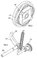
Figure 1 is a sectional plan view showing the apparatus of the invention and its arrangement as regards a rail of an elevator. Said Figure shows the wheel (100), the polygonal cam (110), the ratchet wheel (120), the lock washers (400), the rail (200), the roller (600) and the position of the encoder (500), which is located inside the apparatus. -
Figure 2 shows a perspective view of the wheel, where the auxiliary surface of the wheel or auxiliary wheel (100), the polygonal cam (110) and the ratchet wheel (120) can be seen. -
Figure 3 shows a perspective view of some components of the ratchet mechanism, such as the rocker (130), the follower (140), the ratchet (150) and the actuation of the braking system (300). -
Figures 4A and4B show two front and rear elevational views, respectively, where the rollers (600), the lock washers (400), the auxiliary wheel (100), the follower (140), the rocker (130), the position of the rail (200), the actuation (300), the coil (800) and the contacts (700) can be seen, said contacts being in charge of detecting the derailment and the variation in the pressure setting of the auxiliary wheel on the rail. -
Figure 5A shows a first configuration of the apparatus of the invention where the transmission means comprise a first pinion (310) and second pinion (920) actuating assembly, intended to transmit movement to the braking system by means of a chain or the like encircling the pinion. -
Figure 5B shows a second configuration of the invention where the transmission means comprise a levering actuation (320) and a plurality of levers (910) transmitting movement to the braking system. - Both
figures (5A and5B ) are perspective views of the apparatus of the invention with the two mentioned configurations. - A preferred embodiment of the invention is described below with the aid of the figures.
- The invention relates to an apparatus for detecting overspeed of elevator components selected from a car, a counterweight and combinations thereof, having:
- A wheel, with an auxiliary surface (100) configured to run on a first surface (210) of a travel rail (200) of the elevator component;
- Actuating means (300) for actuating a braking mechanism of the elevator component, characterized in that it comprises speed detecting means for generating a synchronized alternating movement with the speed of the elevator component;
- The speed detecting means are configured to not generate the synchronized alternating movement when a predetermined speed of the elevator component is exceeded and to thus activate the actuating (300) means;
the speed detecting means comprise a ratchet mechanism comprising: - A polygonal-shaped cam (110) on a side of the wheel (100), integral therewith.
- A ratchet wheel (120) on the same side of the wheel (100) and also integral therewith, said ratchet wheel (120) comprising a plurality of projections;
- A rocker (130) having a first end and a second end, provided with:
- A follower (140) at the first end for following the cam profile (110);
- A ratchet (150) at the second end for locking the ratchet wheel (120), thus locking the entire wheel (100).
- According to a first preferred embodiment of the invention, the apparatus further comprises:
- Positioning means, formed by lock washers (400) for pushing the auxiliary surface of the wheel (100) against the first surface (210) of the rail (200) and attempting to prevent the sliding of said auxiliary surface of the wheel on the rail;
- Means of detecting the derailment and the variation in a pressure setting of the auxiliary surface of the wheel (100) on the rail (200).
- According to a second preferred embodiment of the invention, the apparatus further comprises slip monitoring means formed by an encoder (500) configured to control when the auxiliary wheel (100) slips by comparing a rotation speed of the auxiliary wheel (100) with a travel speed of the elevator component.
- According to a third preferred embodiment of the invention, the apparatus further comprises at least one roller (600) configured to roll on a second surface (220) of the rail (200) opposite to the first surface (210) of the rail (200) for:
- Offsetting a stress exerted by the auxiliary wheel (100) on the rail (200) for preventing a transmission of a reaction force on the elevator component;
- Setting a pressure between the auxiliary wheel (100) and the rail (200).
- According to a fourth preferred embodiment of the invention, the apparatus further comprises a remote actuating means or coil (800) for voluntarily engaging the ratchet (150).
- Another embodiment of the invention relates to a system for detecting overspeed of an elevator component characterized in that it comprises at least one apparatus such as the one described above and transmission means joined to the actuating means (300) for transmitting an actuating movement to the braking mechanism of the elevator component.
- In one configuration of the invention:
- The apparatus is arranged in an upper part of the elevator component and the transmission means comprise a plurality of levers (910).
- In another configuration of the invention:
- The apparatus is arranged in a lower part of the elevator component and the transmission means comprise a first pinion (310) and second pinion (920) actuating assembly, which is intended to transmit movement to the braking system by means of a chain or the like encircling it.
Claims (8)
- An apparatus for detecting overspeed of elevator components selected from a car, a counterweight and combinations thereof, having:an auxiliary wheel (100) configured to run on a first surface (210) of a travel rail (200) of the elevator component;actuating means (300) for actuating a braking mechanism of the elevator component;characterized in that:it comprises speed detecting means for generating a synchronized alternating movement with the speed of the elevator component;the speed detecting means are configured to not generate the synchronized alternating movement when a predetermined speed of the elevator component is exceeded and to thus activate the actuating (300) means;the speed detecting means comprise a ratchet mechanism comprising:a polygonal-shaped cam (110) on a first side of the auxiliary wheel (100) integral with said auxiliary wheel (100);a ratchet wheel (120) on the first side of the auxiliary wheel (100) integral with said auxiliary wheel (100), said ratchet wheel (120) comprising a plurality of projections;a rocker (130) having a first end and a second end, provided with:a follower (140) at the first end for following the cam profile (110);a ratchet (150) at the second end for locking the ratchet wheel (120) and thus locking the auxiliary wheel (100).
- The apparatus of claim 1 characterized in that it further comprises:positioning means, comprising a plurality of lock washers (400) for pushing the auxiliary wheel (100) against the first surface (210) of the rail (200) and preventing sliding of the auxiliary wheel (100) on the rail (200);means for detecting derailment and variation in a pressure setting of the auxiliary wheel (100) on the rail (200).
- The apparatus of any of claims 1-2 characterized in that it further comprises slip monitoring means formed by an encoder (500) configured to control when the auxiliary wheel (100) slips by comparing a rotation speed of the auxiliary wheel (100) with a travel speed of the elevator component.
- The apparatus of any of claims 1-3 characterized in that it further comprises at least one roller (600) configured to roll on a second surface (220) of the rail (200) opposite to the first surface (210) of the rail (200) for:offsetting a stress exerted by the auxiliary wheel (100) on the rail (200) for preventing transmission of a reaction force on the elevator component;setting a pressure between the auxiliary wheel (100) and the rail (200).
- The apparatus of any of claims 1-4 characterized in that it further comprises remote actuating means or coil (800) for engaging the ratchet (150) voluntarily.
- A system for detecting overspeed of elevator components selected from a car, a counterweight and combinations thereof, characterized in that it comprises at least one apparatus according to any of claims 1-6 and transmission means joined to the actuating means (300) for transmitting an actuating movement to the braking mechanism of the elevator component.
- The system of claim 6, arranged in an upper part of the elevator component, characterized in that the transmission means for transmitting the actuating movement to the braking mechanism comprise a plurality of levers (910).
- The system of claim 6, arranged in a lower part of the elevator component, characterized in that the transmission means for transmitting the actuating movement to the braking mechanism comprise a first pinion (310) and second pinion (920) actuating assembly, where second pinion (920) is configured to transmit movement to the braking system by means of a chain meshing in said second pinion (920).
Priority Applications (3)
| Application Number | Priority Date | Filing Date | Title |
|---|---|---|---|
| ES07380228T ES2348101T3 (en) | 2007-08-03 | 2007-08-03 | APPARATUS AND SYSTEM TO DETECT AN EXCESS OF SPEED OF A BOX FOR ELEVATORS. |
| EP20070380228 EP2020397B1 (en) | 2007-08-03 | 2007-08-03 | Apparatus and system for detecting elevator car overspeed |
| DE200760007319 DE602007007319D1 (en) | 2007-08-03 | 2007-08-03 | Device and system for detecting increased speed of an elevator car |
Applications Claiming Priority (1)
| Application Number | Priority Date | Filing Date | Title |
|---|---|---|---|
| EP20070380228 EP2020397B1 (en) | 2007-08-03 | 2007-08-03 | Apparatus and system for detecting elevator car overspeed |
Publications (2)
| Publication Number | Publication Date |
|---|---|
| EP2020397A1 true EP2020397A1 (en) | 2009-02-04 |
| EP2020397B1 EP2020397B1 (en) | 2010-06-23 |
Family
ID=38776201
Family Applications (1)
| Application Number | Title | Priority Date | Filing Date |
|---|---|---|---|
| EP20070380228 Expired - Fee Related EP2020397B1 (en) | 2007-08-03 | 2007-08-03 | Apparatus and system for detecting elevator car overspeed |
Country Status (3)
| Country | Link |
|---|---|
| EP (1) | EP2020397B1 (en) |
| DE (1) | DE602007007319D1 (en) |
| ES (1) | ES2348101T3 (en) |
Cited By (2)
| Publication number | Priority date | Publication date | Assignee | Title |
|---|---|---|---|---|
| DE102009055768A1 (en) * | 2009-11-25 | 2011-05-26 | Lödige Fördertechnik GmbH | Device and method for securing, in particular the crash, of elevators and lifting devices |
| EP3553011A1 (en) * | 2018-04-13 | 2019-10-16 | Otis Elevator Company | Overspeed detection and guiding devices for elevator systems |
Citations (6)
| Publication number | Priority date | Publication date | Assignee | Title |
|---|---|---|---|---|
| DE2857376C2 (en) * | 1978-01-21 | 1981-10-01 | Thyssen Aufzüge GmbH, 7303 Neuhausen | Speed limiter |
| EP0121711A2 (en) * | 1983-03-09 | 1984-10-17 | Bongers & Deimann | Velocity limiting device for a lift |
| US5065845A (en) * | 1990-09-13 | 1991-11-19 | Pearson David B | Speed governor safety device for stopping an elevator car |
| ES2184612A1 (en) | 2001-05-25 | 2003-04-01 | De Vera Savera Sa | Speed limiting system for lifts |
| DE10147629A1 (en) | 2001-09-27 | 2003-04-24 | Gerhard Schlosser | Lift (elevator) with cabin speed limiter had speed limiter drive wheel driven by guide rail fulfilling triggering function for brake catcher on cabin |
| EP1516842A2 (en) | 2003-09-18 | 2005-03-23 | Aufzugevolution Schlosser & Schneider GmbH | Elevator control system |
-
2007
- 2007-08-03 EP EP20070380228 patent/EP2020397B1/en not_active Expired - Fee Related
- 2007-08-03 DE DE200760007319 patent/DE602007007319D1/en active Active
- 2007-08-03 ES ES07380228T patent/ES2348101T3/en active Active
Patent Citations (6)
| Publication number | Priority date | Publication date | Assignee | Title |
|---|---|---|---|---|
| DE2857376C2 (en) * | 1978-01-21 | 1981-10-01 | Thyssen Aufzüge GmbH, 7303 Neuhausen | Speed limiter |
| EP0121711A2 (en) * | 1983-03-09 | 1984-10-17 | Bongers & Deimann | Velocity limiting device for a lift |
| US5065845A (en) * | 1990-09-13 | 1991-11-19 | Pearson David B | Speed governor safety device for stopping an elevator car |
| ES2184612A1 (en) | 2001-05-25 | 2003-04-01 | De Vera Savera Sa | Speed limiting system for lifts |
| DE10147629A1 (en) | 2001-09-27 | 2003-04-24 | Gerhard Schlosser | Lift (elevator) with cabin speed limiter had speed limiter drive wheel driven by guide rail fulfilling triggering function for brake catcher on cabin |
| EP1516842A2 (en) | 2003-09-18 | 2005-03-23 | Aufzugevolution Schlosser & Schneider GmbH | Elevator control system |
Cited By (2)
| Publication number | Priority date | Publication date | Assignee | Title |
|---|---|---|---|---|
| DE102009055768A1 (en) * | 2009-11-25 | 2011-05-26 | Lödige Fördertechnik GmbH | Device and method for securing, in particular the crash, of elevators and lifting devices |
| EP3553011A1 (en) * | 2018-04-13 | 2019-10-16 | Otis Elevator Company | Overspeed detection and guiding devices for elevator systems |
Also Published As
| Publication number | Publication date |
|---|---|
| DE602007007319D1 (en) | 2010-08-05 |
| EP2020397B1 (en) | 2010-06-23 |
| ES2348101T3 (en) | 2010-11-30 |
Similar Documents
| Publication | Publication Date | Title |
|---|---|---|
| EP2212230B1 (en) | Elevator | |
| EP3097036B1 (en) | Elevator provided with a safety apparatus arrangement, and a safety apparatus | |
| HU207260B (en) | Clamping device for elevators with speed-limit device arranged on elevator cabin | |
| CA2082773C (en) | Double-sided wedge brake system for an elevator | |
| EP2571799B1 (en) | Integrated elevator safety system | |
| EP3670414B1 (en) | An elevator safety gear trigger and reset system | |
| EP2771267B1 (en) | Speed limiter for a lift | |
| EP3231756B1 (en) | Electronic safety actuation device with a power assembly | |
| CN106553948B (en) | Braking system for a hoisted structure and method of controlling braking of a hoisted structure | |
| US8720262B2 (en) | Testing a speed limiting system of an elevator installation | |
| EP3569547B1 (en) | Safety assembly for braking an elevator car and corresponding method | |
| EP1783087B1 (en) | Double-effect emergency braking apparatus for elevator cars | |
| JP4369156B2 (en) | Equipment for engaging safety brakes for elevator cars | |
| EP2020397B1 (en) | Apparatus and system for detecting elevator car overspeed | |
| AU708452B2 (en) | Lift cage movement arresting mechanism | |
| CN111302194A (en) | Step anti-lifting brake device and escalator equipment | |
| US6296080B1 (en) | Variable traction mechanism for rotary actuated overspeed safety device | |
| CN213326262U (en) | Anti-shearing protection device based on elevator car door linkage | |
| CN111498641A (en) | Parking device for car | |
| KR101436675B1 (en) | Apparatus for opening and closing door of elevator | |
| CN113602932B (en) | Car monitoring devices and vertical conveying equipment | |
| CN212403069U (en) | Parking device for car | |
| SU1104087A2 (en) | Lift cabin catcher | |
| ES2937087A1 (en) | Safety device for parachute activation in lifting systems (Machine-translation by Google Translate, not legally binding) | |
| KR20230161737A (en) | Floor sag prevention device for elevator |
Legal Events
| Date | Code | Title | Description |
|---|---|---|---|
| PUAI | Public reference made under article 153(3) epc to a published international application that has entered the european phase |
Free format text: ORIGINAL CODE: 0009012 |
|
| AK | Designated contracting states |
Kind code of ref document: A1 Designated state(s): AT BE BG CH CY CZ DE DK EE ES FI FR GB GR HU IE IS IT LI LT LU LV MC MT NL PL PT RO SE SI SK TR |
|
| AX | Request for extension of the european patent |
Extension state: AL BA HR MK RS |
|
| 17P | Request for examination filed |
Effective date: 20090422 |
|
| 17Q | First examination report despatched |
Effective date: 20090624 |
|
| AKX | Designation fees paid |
Designated state(s): DE ES FR IT PT |
|
| GRAP | Despatch of communication of intention to grant a patent |
Free format text: ORIGINAL CODE: EPIDOSNIGR1 |
|
| GRAS | Grant fee paid |
Free format text: ORIGINAL CODE: EPIDOSNIGR3 |
|
| GRAA | (expected) grant |
Free format text: ORIGINAL CODE: 0009210 |
|
| AK | Designated contracting states |
Kind code of ref document: B1 Designated state(s): DE ES FR IT PT |
|
| REF | Corresponds to: |
Ref document number: 602007007319 Country of ref document: DE Date of ref document: 20100805 Kind code of ref document: P |
|
| PG25 | Lapsed in a contracting state [announced via postgrant information from national office to epo] |
Ref country code: PT Free format text: LAPSE BECAUSE OF FAILURE TO SUBMIT A TRANSLATION OF THE DESCRIPTION OR TO PAY THE FEE WITHIN THE PRESCRIBED TIME-LIMIT Effective date: 20101025 |
|
| PG25 | Lapsed in a contracting state [announced via postgrant information from national office to epo] |
Ref country code: IT Free format text: LAPSE BECAUSE OF FAILURE TO SUBMIT A TRANSLATION OF THE DESCRIPTION OR TO PAY THE FEE WITHIN THE PRESCRIBED TIME-LIMIT Effective date: 20100623 |
|
| PLBE | No opposition filed within time limit |
Free format text: ORIGINAL CODE: 0009261 |
|
| STAA | Information on the status of an ep patent application or granted ep patent |
Free format text: STATUS: NO OPPOSITION FILED WITHIN TIME LIMIT |
|
| REG | Reference to a national code |
Ref country code: FR Ref legal event code: ST Effective date: 20110502 |
|
| 26N | No opposition filed |
Effective date: 20110324 |
|
| REG | Reference to a national code |
Ref country code: DE Ref legal event code: R119 Ref document number: 602007007319 Country of ref document: DE Effective date: 20110301 |
|
| PG25 | Lapsed in a contracting state [announced via postgrant information from national office to epo] |
Ref country code: DE Free format text: LAPSE BECAUSE OF NON-PAYMENT OF DUE FEES Effective date: 20110301 Ref country code: FR Free format text: LAPSE BECAUSE OF NON-PAYMENT OF DUE FEES Effective date: 20100831 |
|
| PGFP | Annual fee paid to national office [announced via postgrant information from national office to epo] |
Ref country code: ES Payment date: 20140702 Year of fee payment: 8 |
|
| PG25 | Lapsed in a contracting state [announced via postgrant information from national office to epo] |
Ref country code: ES Free format text: LAPSE BECAUSE OF NON-PAYMENT OF DUE FEES Effective date: 20150804 |
|
| REG | Reference to a national code |
Ref country code: ES Ref legal event code: FD2A Effective date: 20180710 |