EP2020175B1 - Harvesting machine with an adjustable transfer device - Google Patents
Harvesting machine with an adjustable transfer device Download PDFInfo
- Publication number
- EP2020175B1 EP2020175B1 EP08012749.1A EP08012749A EP2020175B1 EP 2020175 B1 EP2020175 B1 EP 2020175B1 EP 08012749 A EP08012749 A EP 08012749A EP 2020175 B1 EP2020175 B1 EP 2020175B1
- Authority
- EP
- European Patent Office
- Prior art keywords
- duct
- harvester
- harvester according
- discharge opening
- chute
- Prior art date
- Legal status (The legal status is an assumption and is not a legal conclusion. Google has not performed a legal analysis and makes no representation as to the accuracy of the status listed.)
- Not-in-force
Links
Images


Classifications
-
- A—HUMAN NECESSITIES
- A01—AGRICULTURE; FORESTRY; ANIMAL HUSBANDRY; HUNTING; TRAPPING; FISHING
- A01D—HARVESTING; MOWING
- A01D43/00—Mowers combined with apparatus performing additional operations while mowing
- A01D43/08—Mowers combined with apparatus performing additional operations while mowing with means for cutting up the mown crop, e.g. forage harvesters
- A01D43/086—Mowers combined with apparatus performing additional operations while mowing with means for cutting up the mown crop, e.g. forage harvesters and means for collecting, gathering or loading mown material
- A01D43/087—Mowers combined with apparatus performing additional operations while mowing with means for cutting up the mown crop, e.g. forage harvesters and means for collecting, gathering or loading mown material with controllable discharge spout
Definitions
- the present invention relates to a self-propelled harvester with a transfer device for transferring crop from the harvester to a transport vehicle adjacent to the harvester.
- a transfer device for transferring crop from the harvester to a transport vehicle adjacent to the harvester.
- Such an unloading device generally comprises a so-called discharge chute, a discharge channel which can be placed bridging over the side wall of a transport vehicle in order to load the crop into an upwardly open cargo space of the transport vehicle.
- An exhaust chute is here connected to a vertical shaft of a machine housing, and the shaft comprises two shaft sections, which are rotatably coupled to each other rotatably coupled to a drawbar, so that the end of the discharge chute is always on a via the drawbar connected to the harvester trailer.
- DE 32 24 269 A1 proposes a harvester with an ejection manifold which is divided into two pivotally interconnected sections. In a working position of the discharge chute, the two sections form a continuous line and touch approximately at the level of the roof of a cab of the harvester. The upper portion of the discharge chute can be swung down to the height of the harvester to one for road traffic suitable value, whereby the line is interrupted. Even in the downwardly pivoted position, the chute obstructs the view from the cab.
- a harvesting machine having an ejection elbow which is extensible at its free end by a displaceable element in a substantially horizontal direction.
- the displaceable element allows the uniform loading of a support vehicle with crop even if the harvester is equipped with a far to the side unloading header, especially a corn header, which prevents the escort vehicle from driving close to the harvester. Since the free end of the discharge elbow extends substantially horizontally, no appreciable Hähenationun.g the Ausschkrümmers is connected to the extension or retraction of the displaceable element.
- US 4 148 274 A describes a Ausschkrümrner inconvenience for a snowthrower with manhole sections that are telescopically adjustable in height to adapt to a transport vehicle.
- US 1 336 065 A describes a Heulademaschine with a chute, which comprises two telescopically displaceable tubular shaft sections. The outer of the two shaft sections is extended at its lower end by a downwardly diverging section.
- the object of the present invention is to provide a harvesting machine capable of loading high-level escort vehicles without impairing roadworthiness by the discharge chute, thereby providing a streamlined transition to a processing chamber of the harvesting machine, such as a chopper drum. which extends over a considerable part of the width of the machine housing.
- a consequence of the divergent shape is that there is a gap in the lowered position between the well sections.
- the divergent shape of the second manhole section or of the whole manhole makes it possible to receive a high-width crop stream at an inlet at the lower end of the manhole.
- an inlet width at the lower end of the shaft can be over 700 mm.
- the shaft can be preceded by processing tools such as a header, a chopper drum or cracker rolls of large width, which enable a quick and economical harvesting operation.
- the walls of the second shaft section preferably diverge downward at an angle of at most 20 °, preferably 10 ° to 18 °, to the shaft axis. Smaller angles make for a given inlet width at the bottom of the shaft, an inordinately large height of the shaft required; larger angles have the problem that crops can deposit on the inner surface of the manhole section
- Post-accelerators may be provided on the downwardly diverging shaft. Their task is essentially only the acceleration of the crop in the shaft longitudinal direction, since the merging is achieved to the longitudinal center plane substantially by the shape of the shaft.
- the first manhole section is slidable upward and away from a cab of the harvester.
- the ejection opening is close to the driver's cab and the spur for road driving with a slight projection on the machine housing can be placed in the raised position, the distance of the discharge chute to the cab and thus the range of the discharge chute is increased.
- the spout is also rotatable about a vertical axis with the spout opening as the center.
- the cab obstructs rotation of the discharge chute the less the higher the discharge opening.
- the freedom of rotation of the discharge chute usually only slightly beyond 180 °, it is possible with the invention easily, a freedom of rotation of the chute of 210 ° or more, even better of at least 240 ° or even an unlimited freedom of rotation of the discharge chute to realize.
- the achievable rotational freedom is greater, the higher the ejection opening is on the harvester. Most is already before the Ejection opening is raised above the roof of the cab, the freedom of rotation unlimited.
- a vehicle to be loaded does not necessarily have to travel in a conventional manner next to the harvesting vehicle or behind it, but it may also have a projection relative to the harvesting vehicle. Since the driver of the harvester can see the transport vehicle well while driving without having to look around, the harvesting operation is simplified.
- the latter is preferably pivotable about a horizontal axis adjacent the spout opening from its raised working position to a lowered travel position.
- the invention is applicable to any harvesters that transfer collected crop to a support vehicle using a chute.
- a preferred field of application of the invention are forage harvesters, since in these crops are generally issued during the harvesting process continuously over the chute.
- Fig. 1 shows a field harvester 1 according to the invention in a perspective view obliquely from behind.
- a machine housing 2 of the forage harvester 1 includes a motor for driving the wheels 3, internal units of the machine housing 2 such as a chopper drum and / or cracker rollers and a not shown in the figure, mounted on a front of the forage harvester 1 header.
- internal units of the machine housing 2 such as a chopper drum and / or cracker rollers and a not shown in the figure, mounted on a front of the forage harvester 1 header.
- chopper drum arranged below a driver's cab 4
- grains contained in the crop, in particular maize kernels are crushed by the chopper drum downstream cracker rollers, and finally the crop is discharged into a chute 5 ascending behind the cab 4.
- Fig. 1 shows a field harvester 1 according to the invention in a perspective view obliquely from behind.
- a machine housing 2 of the forage harvester 1 includes a
- a Nachbe deviser 6 is arranged at a lower end of the discharge chute 5. This comprises in a chamber a rotor with a plurality of rotating blades, on the one hand drive the shredded crop by direct contact in the discharge chute 5 and on the other hand form a radial fan whose air flow drives the crop over the entire length of the discharge chute and beyond.
- the discharge chute is composed of two telescopically intermeshing shaft sections 7, 8. At a turntable 9 forming the upper end of the shaft section 7, an ejection elbow 10 is rotatably mounted about a vertical axis of the turntable 9.
- the Figures 1 and 2 show the chute 10 in an orientation that allows the over-loading of crop in a next to the forage harvester 1 driving, not shown transport vehicle.
- An adjustable discharge flap 11 at the free end of the discharge chute 10 is directed steeply downwards, so that the crop is dropped almost vertically down into the transport vehicle.
- Fig. 3 shows a section through the discharge chute 5 along the line III-III of Fig. 2 , While, as in Fig. 2 shown, the dimension of the discharge chute 5 across the cutting plane III-III is substantially constant over the entire height of the discharge chute 5, takes in the plane of the Fig. 3 the width of the discharge chute 5 from the circular turntable 9 from downwards continuously.
- This shape of the discharge chute 5 facilitates the transfer of the chopped crop from the chopper drum extending over a majority of the width of the machine housing 2 into the discharge chute 5.
- the chopper drum may have a width of 800 or even 1000 mm and above; any subsequent cracker rollers are each slightly narrower than the cutterhead to concentrate the crop flow, and an inlet at the bottom of the tray section 8 is again somewhat narrower than the cracker rollers.
- Fig. 3 shows with solid lines the upper manhole section 7 in a maximum raised position. In this position, a lower edge of the shaft section 7 lies completely on the inside at an upper edge of the lower shaft section 8.
- the shaft sections 7, 8 and the adjoining spout 10 form a continuous line for the crop from which, driven by the air flow of the Nachbevanters 6, out of the chopper drum into the cargo compartment of the transport vehicle.
- the walls of the Shaft sections 7, 8 span with the dash-dotted line longitudinal axis of the shaft at an angle ⁇ of 14 °.
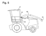
- the discharge chute 10 is connected to the turntable 9 via a hinge 13 with a horizontal axis. If yourself, as in Fig. 4 and 5 shown, the shaft section 7 is in the lowered position, in which the turntable 9 is substantially flush with the surface of the machine housing 2, can be additionally lowered by pivoting in the hinge 13 of the spout 10, so that he just above the machine housing. 2 extends.
- the chute 5 is not exactly vertical but based on the vehicle longitudinal direction towards the rear rising oriented. This has the consequence that in the raised position of the Figures 1 and 2 the turntable 9 is spaced from the rear wall of the cab 4. The greater this distance, the less the rotational freedom of the discharge chute 10 is limited by the vertical axis of the turntable 9 through the cab 4.
- the shaft sections 7, 8 can be so long that in a raised position, when the turntable 9 is above the roof of the car 4 or just below, the discharge chute 10 has a freedom of rotation of 360 °. In the lowered position, however, in particular in Fig. 5 can be seen, the turntable 9 is moved directly to the rear wall of the cab 4, so as to minimize the projection of the free end 11 of the discharge chute 10 to the rear beyond the machine housing 2 addition.
Landscapes
- Life Sciences & Earth Sciences (AREA)
- Environmental Sciences (AREA)
- Harvester Elements (AREA)
- Threshing Machine Elements (AREA)
- Harvesting Machines For Specific Crops (AREA)
Description
Die vorliegende Erfindung betrifft eine selbst fahrende Erntemaschine mit einer Überladeeinrichtung zum Überladen von Erntegut aus der Erntemaschine in ein der Erntemaschine benachbartes Transportfahrzeug. Eine solche Überladeeinrichtung umfasst im Allgemeinen einen so genannten Auswurfkrümmer, einen Austragkanal, der die Bordwand eines Transportfahrzeugs überbrückend platzierbar ist, um das Erntegut in einen nach oben offenen Laderaum des Transportfahrzeugs einzufüllen.The present invention relates to a self-propelled harvester with a transfer device for transferring crop from the harvester to a transport vehicle adjacent to the harvester. Such an unloading device generally comprises a so-called discharge chute, a discharge channel which can be placed bridging over the side wall of a transport vehicle in order to load the crop into an upwardly open cargo space of the transport vehicle.
Es besteht bereits seit längerem die Tendenz, durch immer größere Erntemaschinen den Erntevorgang zu beschleunigen und zu rationalisieren. Damit einher geht das Bedürfnis, große Transportfahrzeuge zum Transportieren des Erntegutes verwenden zu können, um die Zahl der Pendelfahrten zwischen Feld und Lager zum Einbringen des Ernteguts zu minimieren. Diese Transportfahrzeuge können sehr hohe Überladehöhen aufweisen. Um ein solches Transportfahrzeug beladen zu können, muss die Erntemaschine in der Lage sein, das Erntegut auf die benötigte Höhe anzuheben. Wenn das Transportfahrzeug die für den Verkehr auf öffentlichen Straßen maximal zulässige Höhe hat, benötigt folglich die Erntemaschine zum Beladen des Transportfahrzeuges einen Auswurfkrümmer, der über diese maximal zulässige Höhe hinausreicht. Eine solche Erntemaschine dürfte öffentliche Straßen nicht benutzen.There has been a tendency for some time to accelerate and streamline the harvesting process with ever larger harvesters. This is accompanied by the need to be able to use large transport vehicles for transporting the crop in order to minimize the number of shuttle drives between field and camp for the introduction of the crop. These transport vehicles can have very high loading heights. In order to load such a transport vehicle, the harvester must be able to raise the crop to the required height. Consequently, if the transport vehicle has the maximum allowable height for traffic on public roads, the harvester will need to Loading the transport vehicle an ejection, which extends beyond this maximum height. Such a harvester should not use public roads.
Ein weiteres Problem ergibt sich in der Erntemaschine selbst durch die Notwendigkeit, einen störungsfreien Gutfluss durch die gesamte Maschine hindurch zu gewährleisten. Je breiter die Maschine und die an ihr verwendeten Arbeitsaggregate wie etwa Erntevorsatz, Häckseltrommel oder Crackerwalzen werden, um so schwieriger ist es, das Erntegut auf den Querschnitt des Auswurfkrümmers zu bündeln und über diesen auszugeben.Another problem arises in the harvester itself by the need to ensure a trouble-free crop flow through the entire machine. The wider the machine and the working units used on it, such as header, chopper drum or cracker rollers, the more difficult it is to bundle the crop on the cross section of the discharge chute and spend on this.
Aus
Aus
Aufgabe der vorliegenden Erfindung ist, eine Erntemaschine zu schaffen, die in der Lage ist, hochbordige Begleitfahrzeuge zu beladen, ohne dass die Straßenverkehrstauglichkeit durch den Auswurfkrümmer beeinträchtigt ist, und dabei einen strömungsgünstigen Übergang zu einer Verarbeitungskammer der Erntemaschine schafft, wie etwa einer Häckseltrommel, die sich über einen beträchtlichen Teil der Breite des Maschinengehäuses erstreckt.The object of the present invention is to provide a harvesting machine capable of loading high-level escort vehicles without impairing roadworthiness by the discharge chute, thereby providing a streamlined transition to a processing chamber of the harvesting machine, such as a chopper drum. which extends over a considerable part of the width of the machine housing.
Die Aufgabe wird gelöst durch eine Erntemaschine mit den Merkmalen des Anspruchs 1.The object is achieved by a harvesting machine with the features of
Eine Konsequenz der divergenten Form ist, dass in abgesenkter Stellung zwischen den Schachtabschnitten ein Zwischenraum vorhanden ist Wenn erster und zweiter Schachtabschnitt divergent sind, ist eine obere Anschlagstellung des ersten Schachtabschnittes durch einen Kontakt mit dem umgebenden zweiten Schachtabschnitt definiert.A consequence of the divergent shape is that there is a gap in the lowered position between the well sections. When the first and second well sections are divergent, an upper stop position of the first well section is defined by contact with the surrounding second well section.
Die divergente Form des zweiten Schachtabschnitts oder des ganzen Schachts ermöglicht, an einem Einlass am unteren Ende des Schachts einen Gutstrom von hoher Breite aufzunehmen. Insbesondere kann eine Einlassbreite am unteren Ende des Schachts über 700 mm betragen. So können dem Schacht Verarbeitungswerkzeuge wie etwa ein Erntevorsatz, eine Häckseltrommel oder Crackerwalzen großer Breite vorgelagert sein, die einen schnellen und wirtschaftlichen Ernteeinsatz ermöglichen.The divergent shape of the second manhole section or of the whole manhole makes it possible to receive a high-width crop stream at an inlet at the lower end of the manhole. In particular, an inlet width at the lower end of the shaft can be over 700 mm. Thus, the shaft can be preceded by processing tools such as a header, a chopper drum or cracker rolls of large width, which enable a quick and economical harvesting operation.
Vorzugsweise divergieren die wände des zweiten Schachtabschnitts nach unten unter einem Winkel von maximal 20°, vorzugsweise 10° bis 18°, zur Schachtachse. Kleinere Winkel machen bei gegebener Einlassbreite am unteren Ende des Schachts eine unzweckmäßig große Bauhöhe des Schachts erforderlich; größere Winkel haben das Problem, das sich Erntegut an der Innenfläche des Schachtabschnitts ablagern kannThe walls of the second shaft section preferably diverge downward at an angle of at most 20 °, preferably 10 ° to 18 °, to the shaft axis. Smaller angles make for a given inlet width at the bottom of the shaft, an inordinately large height of the shaft required; larger angles have the problem that crops can deposit on the inner surface of the manhole section
An dem nach unten divergierenden Schacht können Nachbeschleuniger vorgesehen sein. Ihre Aufgabe ist im Wesentlichen nur das Beschleunigen des Ernteguts in Schachtlängsrichtung, da das Zusammenführen zur Längsmittelebene im Wesentlichen durch die Gestalt des Schachts erreicht wird.Post-accelerators may be provided on the downwardly diverging shaft. Their task is essentially only the acceleration of the crop in the shaft longitudinal direction, since the merging is achieved to the longitudinal center plane substantially by the shape of the shaft.
Vorzugsweise ist der erste Schachtabschnitt schräg nach oben und fort von einer Fahrerkabine der Erntemaschine verschiebbar. Während somit in der abgesenkten Stellung die Auswurföffnung nahe an der Fahrerkabine liegt und der Auswurfkrümmer für die Straßenfahrt mit geringem Überstand auf dem Maschinengehäuse platziert werden kann, ist in der angehobenen Stellung der Abstand des Auswurfkrümmers zur Fahrerkabine und damit die Reichweite des Auswurfkrümmers vergrößert.Preferably, the first manhole section is slidable upward and away from a cab of the harvester. Thus, while in the lowered position, the ejection opening is close to the driver's cab and the spur for road driving with a slight projection on the machine housing can be placed in the raised position, the distance of the discharge chute to the cab and thus the range of the discharge chute is increased.
Zweckmäßigerweise ist der Auswurfkrümmer ferner um eine vertikale Achse mit der Auswurföffnung als Mittelpunkt drehbar. Allgemein behindert die Fahrerkabine eine Drehung des Auswurfkrümmers um so weniger, je höher die Auswurföffnung liegt. Während bei einem herkömmlichen Feldhäcksler die Drehbewegungsfreiheit des Auswurfkrümmers meist nur wenig über 180° hinaus geht, ist es mit der Erfindung ohne weiteres möglich, eine Drehbewegungsfreiheit des Auswurfkrümmers von 210° oder mehr, besser noch von wenigstens 240° oder gar eine unbeschränkte Drehbewegungsfreiheit des Auswurfkrümmers zu realisieren. Allgemein ist die erreichbare Drehbewegungsfreiheit um so größer, je höher die Auswurföffnung an der Erntemaschine liegt. Meist ist bereits bevor die Auswurföffnung über das Dach der Fahrerkabine angehoben ist, die Drehbewegungsfreiheit unbegrenzt.Conveniently, the spout is also rotatable about a vertical axis with the spout opening as the center. Generally, the cab obstructs rotation of the discharge chute the less the higher the discharge opening. While in a conventional forage harvester, the freedom of rotation of the discharge chute usually only slightly beyond 180 °, it is possible with the invention easily, a freedom of rotation of the chute of 210 ° or more, even better of at least 240 ° or even an unlimited freedom of rotation of the discharge chute to realize. In general, the achievable rotational freedom is greater, the higher the ejection opening is on the harvester. Most is already before the Ejection opening is raised above the roof of the cab, the freedom of rotation unlimited.
Da der Auswurfkrümmer somit nach vorn geschwenkt sein kann, muss ein zu beladendes Fahrzeug nicht zwangsläufig in herkömmlicher Weise neben dem Erntefahrzeug oder hinter ihm her fahren, sondern es kann auch einen Vorsprung gegenüber dem Erntefahrzeug haben. Da der Fahrer der Erntemaschine das Transportfahrzeug beim Fahren gut sehen kann, ohne sich umschauen zu müssen, ist der Erntebetrieb vereinfacht.Since the discharge chute can thus be pivoted forward, a vehicle to be loaded does not necessarily have to travel in a conventional manner next to the harvesting vehicle or behind it, but it may also have a projection relative to the harvesting vehicle. Since the driver of the harvester can see the transport vehicle well while driving without having to look around, the harvesting operation is simplified.
Aus der über eine Oberseite des Maschinengehäuses aufragenden Arbeitsstellung ist der Auswurfkrümmer wenigstens bis in eine mit der Oberseite im Wesentlichen bündige Stellung absenkbar, um die Erntemaschine für Straßenfahrt tauglich zu machen.From the projecting over an upper side of the machine housing working position of the chute is lowered at least up to a top with the top substantially flush position to make the harvester suitable for road travel.
Um den Auswurfkrümmer für die Fahrt an dem Maschinengehäuse zu sichern und/oder eine Sichtbeeinträchtigung des Fahrers durch den Auswurfkrümmer zu minimieren, ist letzterer vorzugsweise um eine der Auswurföffnung benachbarte horizontale Achse aus seiner angehobenen Arbeitsstellung in eine abgesenkte Fahrstellung schwenkbar.In order to secure the spout for travel on the machine housing and / or to minimize driver discomfort through the spout, the latter is preferably pivotable about a horizontal axis adjacent the spout opening from its raised working position to a lowered travel position.
Die Erfindung ist anwendbar für beliebige Erntemaschinen, die gesammeltes Erntegut mit Hilfe eines Auswurfkrümmers an ein Begleitfahrzeug übergeben. Ein bevorzugtes Anwendungsgebiet der Erfindung sind allerdings Feldhäcksler, da bei diesen im Allgemeinen Erntegut während des Erntevorganges kontinuierlich über den Auswurfkrümmer ausgegeben wird.The invention is applicable to any harvesters that transfer collected crop to a support vehicle using a chute. A preferred field of application of the invention, however, are forage harvesters, since in these crops are generally issued during the harvesting process continuously over the chute.
Weitere Merkmale und Vorteile der Erfindung ergeben sich aus der nachfolgenden Beschreibung von Ausführungsbeispielen unter Bezugnahme auf die beigefügten Figuren. Es zeigen:
- Fig. 1
- eine perspektivische Ansicht eines erfindungsgemäßen Feldhäckslers mit Auswurfkrümmer in Arbeitsstellung;
- Fig. 2
- eine teilweise aufgeschnittene Seitenansicht des Feldhäckslers;
- Fig. 3
- einen Detailschnitt aus
Fig. 2 ; - Fig. 4
- eine perspektivische Ansicht des Feldhäckslers mit Auswurfkrümmer in Fahrtstellung; und
- Fig. 5
- eine Seitenansicht des Feldhäckslers mit Auswurfkrümmer in Fahrtstellung.
- Fig. 1
- a perspective view of a forage harvester invention with chute in working position;
- Fig. 2
- a partially cutaway side view of the forage harvester;
- Fig. 3
- a detail section
Fig. 2 ; - Fig. 4
- a perspective view of the forage harvester with chute in driving position; and
- Fig. 5
- a side view of the forage harvester with chute in driving position.
Der Auswurfschacht ist aus zwei teleskopisch ineinandergreifenden Schachtabschnitten 7, 8 zusammengesetzt. An einem den oberen Abschluss des Schachtabschnittes 7 bildenden Drehkranz 9 ist ein Auswurfkrümmer 10 um eine vertikale Achse des Drehkranzes 9 drehbar montiert. Die
Aus der in
Es ist leicht nachzuvollziehen, dass in dieser abgesenkten Konfiguration die Ausgabe von Erntegut nicht ohne Weiteres möglich ist. Selbst wenn man annimmt, dass der Schachtabschnitt 7 in seiner gestrichelt dargestellten abgesenkten Stellung den Nachbeschleuniger 6 nicht blockiert, würde ein von ihm angetriebener Luftstrom und das von diesem mitgenommene gehäckselte Erntegut nicht nur über den Schachtabschnitt 7 und den daran angeschlossenen Auswurfkrümmer 10 ausgegeben, sondern auch durch die Zwischenräume 12, und würde daher das Transportfahrzeug nicht erreichen. Die gestrichelt dargestellte abgesenkte Stellung ist daher im Wesentlichen nur geeignet, die Höhe des Feldhäckslers 1 für den Fall zu verringern, dass dieser abgestellt werden soll oder öffentliche Straßen befahren muss.It is easy to see that in this lowered configuration, crop output is not readily available. Even if it is assumed that the
Als eine zusätzliche Maßnahme zur Höhenreduzierung des Feldhäckslers 1 bei Straßenfahrt ist der Auswurfkrümmer 10 mit dem Drehkranz 9 über ein Scharnier 13 mit horizontaler Achse verbunden. Wenn sich, wie in
Der Auswurfschacht 5 ist nicht exakt vertikal sondern bezogen auf die Fahrzeuglängsrichtung nach hinten ansteigend orientiert. Dies hat zur Folge, dass in der angehobenen Stellung der
- 11
- FeldhäckslerForage
- 22
- Maschinengehäusemachine housing
- 33
- Räderbikes
- 44
- Fahrerkabinecab
- 55
- Auswurfschachtchute
- 66
- Nachbeschleunigerpost-accelerator
- 77
- Schachtabschnittchute section
- 88th
- Schachtabschnittchute section
- 99
- Drehkranzslewing ring
- 1010
- Auswurfkrümmerchute
- 1111
- Abschnittsection
- 1212
- Zwischenraumgap
- 1313
- Scharnierhinge
Claims (10)
- Harvester (1), having a machinery enclosure (2) which comprises a duct having at least a first portion (7) and a second portion (8), a discharge opening (9) forming an upper end of the first portion (7) of the duct and the second portion (8) of the duct being divergent in the downward direction, and having a discharge chute (10) movably mounted on the discharge opening (9), the discharge opening (9) being adjustable in height on the machinery enclosure (2), the portions (7, 8) of the duct being displaceable relative to one another telescopically and the first portion (7) of the duct, which has the discharge opening (9), engaging in the second portion (8) of the duct, characterised in that the first portion (7) of the duct too is divergent in the downward direction.
- Harvester according to claim 1, characterised in that the walls of the second portion (8) of the duct diverge in the downward direction from the axis of the duct at an angle (θ) of not more than 20°.
- Harvester according to claim 1 or 2, characterised in that the duct has an inlet of a width of at least 700 mm.
- Harvester according to one of claims 1 to 3, characterised in that the first portion (7) of the duct is displaceable obliquely upwards and away from a driver's cab (4) of the harvester (1).
- Harvester according to one of the preceding claims, characterised in that the discharge opening (9) can be raised to a point above the roof of a driver's cab (4).
- Harvester according to one of the preceding claims, characterised in that the discharge chute (10) is rotatable on a vertical axis with the discharge opening (9) as a centre.
- Harvester according to claim 6, characterised in that the freedom of movement in rotation of the discharge chute (10) on the vertical axis is at least 240° and preferably 360°.
- Harvester according to one of the preceding claims, characterised in that the discharge opening (9) can be lowered from a position in which it projects above a top face of the machinery enclosure (2) to a position in which it is substantially flush with the top face.
- Harvester according to one of the preceding claims, characterised in that the discharge chute (10) can be pivoted, on a horizontal axis adjacent to the discharge opening, from a raised working position to a lowered travelling position.
- Harvester according to one of the preceding claims, characterised in that it is a forage harvester (1).
Applications Claiming Priority (1)
| Application Number | Priority Date | Filing Date | Title |
|---|---|---|---|
| DE102007036799A DE102007036799A1 (en) | 2007-08-03 | 2007-08-03 | Harvester with adjustable transfer device |
Publications (2)
| Publication Number | Publication Date |
|---|---|
| EP2020175A1 EP2020175A1 (en) | 2009-02-04 |
| EP2020175B1 true EP2020175B1 (en) | 2014-09-10 |
Family
ID=39926558
Family Applications (1)
| Application Number | Title | Priority Date | Filing Date |
|---|---|---|---|
| EP08012749.1A Not-in-force EP2020175B1 (en) | 2007-08-03 | 2008-07-15 | Harvesting machine with an adjustable transfer device |
Country Status (4)
| Country | Link |
|---|---|
| US (1) | US8438821B2 (en) |
| EP (1) | EP2020175B1 (en) |
| DE (1) | DE102007036799A1 (en) |
| RU (1) | RU2463767C2 (en) |
Families Citing this family (5)
| Publication number | Priority date | Publication date | Assignee | Title |
|---|---|---|---|---|
| US20110011046A1 (en) * | 2009-07-14 | 2011-01-20 | Byard Robert B | Discharge diverter for lawnmower and similar lawn care apparatus |
| US8528845B2 (en) * | 2010-05-07 | 2013-09-10 | Anders Ragnarsson | Flexible chipper chute having two chip discharge configurations |
| USD667850S1 (en) * | 2012-02-13 | 2012-09-25 | J. & M. Manufacturing Co., Inc. | Grain auger housing having an askewed discharge outlet attachment |
| JP6296355B2 (en) * | 2014-10-28 | 2018-03-20 | 井関農機株式会社 | Combine |
| AR116122A1 (en) * | 2018-10-02 | 2021-04-07 | Accorroni Rivas Bruno | SUGAR CANE BIOMASS MINCING MACHINE INCORPORATED ON A HARVESTER |
Citations (1)
| Publication number | Priority date | Publication date | Assignee | Title |
|---|---|---|---|---|
| US1336065A (en) * | 1915-09-24 | 1920-04-06 | Nicholas M Bowers | Hay-loader |
Family Cites Families (27)
| Publication number | Priority date | Publication date | Assignee | Title |
|---|---|---|---|---|
| US708082A (en) * | 1902-03-17 | 1902-09-02 | Frank L Sackett | Chute. |
| US1618531A (en) * | 1926-05-10 | 1927-02-22 | Francis H Hampton | Funnel |
| US2253794A (en) * | 1940-03-22 | 1941-08-26 | Raymond H Lindholm | Ensilage cutter attachment for tractors |
| US2634570A (en) * | 1949-05-06 | 1953-04-14 | Idaho Egg Producers | Horizontal topper and loader |
| US2778510A (en) * | 1952-10-14 | 1957-01-22 | Cobey Corp | Swivel discharge stack for agricultural harvester |
| US3070940A (en) * | 1958-07-17 | 1963-01-01 | Patent Concern Nv | Forage harvesters |
| US3464471A (en) * | 1967-07-06 | 1969-09-02 | Case Co J I | Blower spout mechanism |
| US3911650A (en) * | 1974-01-02 | 1975-10-14 | Donald F Johnson | Hay loading apparatus |
| GB1527353A (en) | 1974-10-15 | 1978-10-04 | Agfa Gevaert | Apparatus for use in processing sheets or strips of recording material |
| CA1065904A (en) * | 1977-08-31 | 1979-11-06 | Adrien Vohl And Fils Limitee | Ejection tube assembly for a snowblower |
| AT381832B (en) | 1981-07-07 | 1986-12-10 | Poettinger Ohg Alois | EJECTOR FOR AGRICULTURAL MACHINERY |
| US4821495A (en) * | 1987-03-23 | 1989-04-18 | Deere & Company | Blower and discharge spout assembly |
| SU1584805A1 (en) * | 1988-09-20 | 1990-08-15 | Производственное объединение "Херсонский комбайновый завод им.Г.И.Петровского" | Unloading silage duct |
| US4996831A (en) * | 1990-05-07 | 1991-03-05 | Deere & Company | Cotton basket extension latch |
| DE4039720A1 (en) * | 1990-12-13 | 1992-06-17 | Claas Ohg | FIELD CHOPPER |
| SU1752255A1 (en) * | 1990-12-29 | 1992-08-07 | Головное Специализированное Конструкторское Бюро По Комплексу Кормоуборочных Машин Производственного Объединения "Гомсельмаш" | Unloading chute of agricultural harvester |
| US5857908A (en) * | 1996-12-18 | 1999-01-12 | Case Corporation | Duct structure for a cotton harvester |
| DE29700426U1 (en) * | 1997-01-11 | 1997-05-15 | Claas KGaA, 33428 Harsewinkel | Self-propelled forage harvester with a swiveling flap located at the end of its discharge tube |
| DE10021657C2 (en) * | 2000-05-04 | 2002-08-01 | Krone Bernhard Gmbh Maschf | Harvester, especially self-propelled forage harvesters |
| RU2258350C2 (en) * | 2001-12-28 | 2005-08-20 | Чинов Александр Константинович | Discharge pipeline of root harvesting combine |
| DE10211706A1 (en) | 2002-03-16 | 2003-09-25 | Deere & Co | Discharge device for an agricultural harvesting machine |
| DE10228880B4 (en) * | 2002-06-27 | 2005-09-08 | Jakob Voets Ing. Grad. Gmbh & Co. Kg Rheinische Landschaftspflege | Mowing device for lawn and landscape meadow maintenance with a device for receiving and shredding crops |
| DE10240219A1 (en) * | 2002-08-28 | 2004-03-11 | Claas Selbstfahrende Erntemaschinen Gmbh | Device for controlling a transfer device |
| DE10335583B4 (en) * | 2003-07-31 | 2012-07-26 | Claas Selbstfahrende Erntemaschinen Gmbh | Loading device for agricultural harvester |
| SE526228C2 (en) * | 2003-10-30 | 2005-08-02 | Sandvik Intellectual Property | Bulk Loading device |
| US7117817B2 (en) * | 2004-08-03 | 2006-10-10 | Troy Overstreet | Animal feed harvesting and dispensing system |
| US7204752B2 (en) * | 2005-09-19 | 2007-04-17 | Cnh America Llc | Automatically deployable and storable cover apparatus for directing cotton flow from a conveyor duct of a cotton harvester to a cotton receiver thereof |
-
2007
- 2007-08-03 DE DE102007036799A patent/DE102007036799A1/en not_active Withdrawn
-
2008
- 2008-07-15 EP EP08012749.1A patent/EP2020175B1/en not_active Not-in-force
- 2008-07-31 RU RU2008131474/13A patent/RU2463767C2/en active
- 2008-08-04 US US12/185,784 patent/US8438821B2/en not_active Expired - Fee Related
Patent Citations (1)
| Publication number | Priority date | Publication date | Assignee | Title |
|---|---|---|---|---|
| US1336065A (en) * | 1915-09-24 | 1920-04-06 | Nicholas M Bowers | Hay-loader |
Also Published As
| Publication number | Publication date |
|---|---|
| RU2463767C2 (en) | 2012-10-20 |
| RU2008131474A (en) | 2010-02-10 |
| DE102007036799A1 (en) | 2009-02-05 |
| US8438821B2 (en) | 2013-05-14 |
| EP2020175A1 (en) | 2009-02-04 |
| US20090113866A1 (en) | 2009-05-07 |
Similar Documents
| Publication | Publication Date | Title |
|---|---|---|
| EP1074175B1 (en) | Distributor for the residues of crops ejected from a combine | |
| DE60127193T2 (en) | Grain tank of a harvester | |
| EP0580026B1 (en) | Mower with cutter-housing and rearward ejection shaft with directing device | |
| EP1344446A1 (en) | Discharging device of an agricultural harvesting machine | |
| EP2020175B1 (en) | Harvesting machine with an adjustable transfer device | |
| EP3078256B1 (en) | Agricultural harvest wagon with dosing apparatus and broad distribution | |
| DE202016008886U1 (en) | Grain handling devices of a rear grain wagon for an agricultural harvesting combine or a combine harvester | |
| EP1068791A1 (en) | Self-propelled mower with conveyors | |
| EP2959766B1 (en) | Harvester and method of operating same | |
| EP1588601B1 (en) | Harvesting machine with a discharging device | |
| DE3419997A1 (en) | Fodder-mixing truck | |
| EP1894463B1 (en) | Agricultural harvester with an excess load device | |
| AT513427B1 (en) | Harvest truck for picking up and transporting plants or parts of plants | |
| DE69816754T2 (en) | Agricultural machine with elevator system | |
| EP1330951B1 (en) | Apparatus for mixing feed | |
| DE20201638U1 (en) | Transfer car for granular crops | |
| EP3069596B1 (en) | Forage harvester | |
| DE1942733A1 (en) | Harvester | |
| DE102008050562B4 (en) | wagon | |
| DE69021061T2 (en) | Emptying device for the collecting container of a combine harvester. | |
| DE102022002792B3 (en) | Transport and reloading wagons and method for discharging a load from a transport and reloading wagon | |
| BE1027579B1 (en) | Forage harvester with two-part transition housing | |
| BE1027602B1 (en) | Forage harvester with swiveling transition housing | |
| EP0260334B1 (en) | Evacuation device | |
| EP2181578A2 (en) | Combine harvester and harvesting method |
Legal Events
| Date | Code | Title | Description |
|---|---|---|---|
| PUAI | Public reference made under article 153(3) epc to a published international application that has entered the european phase |
Free format text: ORIGINAL CODE: 0009012 |
|
| 17P | Request for examination filed |
Effective date: 20080804 |
|
| AK | Designated contracting states |
Kind code of ref document: A1 Designated state(s): AT BE BG CH CY CZ DE DK EE ES FI FR GB GR HR HU IE IS IT LI LT LU LV MC MT NL NO PL PT RO SE SI SK TR |
|
| AX | Request for extension of the european patent |
Extension state: AL BA MK RS |
|
| 17Q | First examination report despatched |
Effective date: 20090804 |
|
| AKX | Designation fees paid |
Designated state(s): AT BE BG CH CY CZ DE DK EE ES FI FR GB GR HR HU IE IS IT LI LT LU LV MC MT NL NO PL PT RO SE SI SK TR |
|
| GRAP | Despatch of communication of intention to grant a patent |
Free format text: ORIGINAL CODE: EPIDOSNIGR1 |
|
| INTG | Intention to grant announced |
Effective date: 20140120 |
|
| GRAS | Grant fee paid |
Free format text: ORIGINAL CODE: EPIDOSNIGR3 |
|
| GRAA | (expected) grant |
Free format text: ORIGINAL CODE: 0009210 |
|
| AK | Designated contracting states |
Kind code of ref document: B1 Designated state(s): AT BE BG CH CY CZ DE DK EE ES FI FR GB GR HR HU IE IS IT LI LT LU LV MC MT NL NO PL PT RO SE SI SK TR |
|
| REG | Reference to a national code |
Ref country code: GB Ref legal event code: FG4D Free format text: NOT ENGLISH |
|
| REG | Reference to a national code |
Ref country code: CH Ref legal event code: EP |
|
| REG | Reference to a national code |
Ref country code: IE Ref legal event code: FG4D Free format text: LANGUAGE OF EP DOCUMENT: GERMAN |
|
| REG | Reference to a national code |
Ref country code: AT Ref legal event code: REF Ref document number: 686184 Country of ref document: AT Kind code of ref document: T Effective date: 20141015 |
|
| REG | Reference to a national code |
Ref country code: DE Ref legal event code: R096 Ref document number: 502008012183 Country of ref document: DE Effective date: 20141023 |
|
| PG25 | Lapsed in a contracting state [announced via postgrant information from national office to epo] |
Ref country code: NO Free format text: LAPSE BECAUSE OF FAILURE TO SUBMIT A TRANSLATION OF THE DESCRIPTION OR TO PAY THE FEE WITHIN THE PRESCRIBED TIME-LIMIT Effective date: 20141210 Ref country code: GR Free format text: LAPSE BECAUSE OF FAILURE TO SUBMIT A TRANSLATION OF THE DESCRIPTION OR TO PAY THE FEE WITHIN THE PRESCRIBED TIME-LIMIT Effective date: 20141211 Ref country code: LT Free format text: LAPSE BECAUSE OF FAILURE TO SUBMIT A TRANSLATION OF THE DESCRIPTION OR TO PAY THE FEE WITHIN THE PRESCRIBED TIME-LIMIT Effective date: 20140910 Ref country code: FI Free format text: LAPSE BECAUSE OF FAILURE TO SUBMIT A TRANSLATION OF THE DESCRIPTION OR TO PAY THE FEE WITHIN THE PRESCRIBED TIME-LIMIT Effective date: 20140910 Ref country code: SE Free format text: LAPSE BECAUSE OF FAILURE TO SUBMIT A TRANSLATION OF THE DESCRIPTION OR TO PAY THE FEE WITHIN THE PRESCRIBED TIME-LIMIT Effective date: 20140910 Ref country code: ES Free format text: LAPSE BECAUSE OF FAILURE TO SUBMIT A TRANSLATION OF THE DESCRIPTION OR TO PAY THE FEE WITHIN THE PRESCRIBED TIME-LIMIT Effective date: 20140910 |
|
| REG | Reference to a national code |
Ref country code: NL Ref legal event code: VDEP Effective date: 20140910 |
|
| REG | Reference to a national code |
Ref country code: LT Ref legal event code: MG4D |
|
| PG25 | Lapsed in a contracting state [announced via postgrant information from national office to epo] |
Ref country code: LV Free format text: LAPSE BECAUSE OF FAILURE TO SUBMIT A TRANSLATION OF THE DESCRIPTION OR TO PAY THE FEE WITHIN THE PRESCRIBED TIME-LIMIT Effective date: 20140910 Ref country code: HR Free format text: LAPSE BECAUSE OF FAILURE TO SUBMIT A TRANSLATION OF THE DESCRIPTION OR TO PAY THE FEE WITHIN THE PRESCRIBED TIME-LIMIT Effective date: 20140910 Ref country code: CY Free format text: LAPSE BECAUSE OF FAILURE TO SUBMIT A TRANSLATION OF THE DESCRIPTION OR TO PAY THE FEE WITHIN THE PRESCRIBED TIME-LIMIT Effective date: 20140910 |
|
| PG25 | Lapsed in a contracting state [announced via postgrant information from national office to epo] |
Ref country code: NL Free format text: LAPSE BECAUSE OF FAILURE TO SUBMIT A TRANSLATION OF THE DESCRIPTION OR TO PAY THE FEE WITHIN THE PRESCRIBED TIME-LIMIT Effective date: 20140910 |
|
| PG25 | Lapsed in a contracting state [announced via postgrant information from national office to epo] |
Ref country code: SK Free format text: LAPSE BECAUSE OF FAILURE TO SUBMIT A TRANSLATION OF THE DESCRIPTION OR TO PAY THE FEE WITHIN THE PRESCRIBED TIME-LIMIT Effective date: 20140910 Ref country code: EE Free format text: LAPSE BECAUSE OF FAILURE TO SUBMIT A TRANSLATION OF THE DESCRIPTION OR TO PAY THE FEE WITHIN THE PRESCRIBED TIME-LIMIT Effective date: 20140910 Ref country code: RO Free format text: LAPSE BECAUSE OF FAILURE TO SUBMIT A TRANSLATION OF THE DESCRIPTION OR TO PAY THE FEE WITHIN THE PRESCRIBED TIME-LIMIT Effective date: 20140910 Ref country code: PT Free format text: LAPSE BECAUSE OF FAILURE TO SUBMIT A TRANSLATION OF THE DESCRIPTION OR TO PAY THE FEE WITHIN THE PRESCRIBED TIME-LIMIT Effective date: 20150112 Ref country code: CZ Free format text: LAPSE BECAUSE OF FAILURE TO SUBMIT A TRANSLATION OF THE DESCRIPTION OR TO PAY THE FEE WITHIN THE PRESCRIBED TIME-LIMIT Effective date: 20140910 Ref country code: IS Free format text: LAPSE BECAUSE OF FAILURE TO SUBMIT A TRANSLATION OF THE DESCRIPTION OR TO PAY THE FEE WITHIN THE PRESCRIBED TIME-LIMIT Effective date: 20150110 |
|
| PG25 | Lapsed in a contracting state [announced via postgrant information from national office to epo] |
Ref country code: PL Free format text: LAPSE BECAUSE OF FAILURE TO SUBMIT A TRANSLATION OF THE DESCRIPTION OR TO PAY THE FEE WITHIN THE PRESCRIBED TIME-LIMIT Effective date: 20140910 |
|
| REG | Reference to a national code |
Ref country code: DE Ref legal event code: R097 Ref document number: 502008012183 Country of ref document: DE |
|
| PLBE | No opposition filed within time limit |
Free format text: ORIGINAL CODE: 0009261 |
|
| STAA | Information on the status of an ep patent application or granted ep patent |
Free format text: STATUS: NO OPPOSITION FILED WITHIN TIME LIMIT |
|
| PG25 | Lapsed in a contracting state [announced via postgrant information from national office to epo] |
Ref country code: DK Free format text: LAPSE BECAUSE OF FAILURE TO SUBMIT A TRANSLATION OF THE DESCRIPTION OR TO PAY THE FEE WITHIN THE PRESCRIBED TIME-LIMIT Effective date: 20140910 |
|
| 26N | No opposition filed |
Effective date: 20150611 |
|
| PG25 | Lapsed in a contracting state [announced via postgrant information from national office to epo] |
Ref country code: IT Free format text: LAPSE BECAUSE OF FAILURE TO SUBMIT A TRANSLATION OF THE DESCRIPTION OR TO PAY THE FEE WITHIN THE PRESCRIBED TIME-LIMIT Effective date: 20140910 |
|
| PG25 | Lapsed in a contracting state [announced via postgrant information from national office to epo] |
Ref country code: SI Free format text: LAPSE BECAUSE OF FAILURE TO SUBMIT A TRANSLATION OF THE DESCRIPTION OR TO PAY THE FEE WITHIN THE PRESCRIBED TIME-LIMIT Effective date: 20140910 |
|
| PG25 | Lapsed in a contracting state [announced via postgrant information from national office to epo] |
Ref country code: MC Free format text: LAPSE BECAUSE OF FAILURE TO SUBMIT A TRANSLATION OF THE DESCRIPTION OR TO PAY THE FEE WITHIN THE PRESCRIBED TIME-LIMIT Effective date: 20140910 |
|
| REG | Reference to a national code |
Ref country code: CH Ref legal event code: PL |
|
| GBPC | Gb: european patent ceased through non-payment of renewal fee |
Effective date: 20150715 |
|
| PG25 | Lapsed in a contracting state [announced via postgrant information from national office to epo] |
Ref country code: LU Free format text: LAPSE BECAUSE OF FAILURE TO SUBMIT A TRANSLATION OF THE DESCRIPTION OR TO PAY THE FEE WITHIN THE PRESCRIBED TIME-LIMIT Effective date: 20150715 |
|
| REG | Reference to a national code |
Ref country code: IE Ref legal event code: MM4A |
|
| PG25 | Lapsed in a contracting state [announced via postgrant information from national office to epo] |
Ref country code: LI Free format text: LAPSE BECAUSE OF NON-PAYMENT OF DUE FEES Effective date: 20150731 Ref country code: CH Free format text: LAPSE BECAUSE OF NON-PAYMENT OF DUE FEES Effective date: 20150731 Ref country code: GB Free format text: LAPSE BECAUSE OF NON-PAYMENT OF DUE FEES Effective date: 20150715 |
|
| REG | Reference to a national code |
Ref country code: FR Ref legal event code: ST Effective date: 20160331 |
|
| PG25 | Lapsed in a contracting state [announced via postgrant information from national office to epo] |
Ref country code: FR Free format text: LAPSE BECAUSE OF NON-PAYMENT OF DUE FEES Effective date: 20150731 |
|
| PG25 | Lapsed in a contracting state [announced via postgrant information from national office to epo] |
Ref country code: IE Free format text: LAPSE BECAUSE OF NON-PAYMENT OF DUE FEES Effective date: 20150715 |
|
| REG | Reference to a national code |
Ref country code: AT Ref legal event code: MM01 Ref document number: 686184 Country of ref document: AT Kind code of ref document: T Effective date: 20150715 |
|
| PG25 | Lapsed in a contracting state [announced via postgrant information from national office to epo] |
Ref country code: AT Free format text: LAPSE BECAUSE OF NON-PAYMENT OF DUE FEES Effective date: 20150715 |
|
| PG25 | Lapsed in a contracting state [announced via postgrant information from national office to epo] |
Ref country code: MT Free format text: LAPSE BECAUSE OF FAILURE TO SUBMIT A TRANSLATION OF THE DESCRIPTION OR TO PAY THE FEE WITHIN THE PRESCRIBED TIME-LIMIT Effective date: 20140910 |
|
| PG25 | Lapsed in a contracting state [announced via postgrant information from national office to epo] |
Ref country code: HU Free format text: LAPSE BECAUSE OF FAILURE TO SUBMIT A TRANSLATION OF THE DESCRIPTION OR TO PAY THE FEE WITHIN THE PRESCRIBED TIME-LIMIT; INVALID AB INITIO Effective date: 20080715 Ref country code: BG Free format text: LAPSE BECAUSE OF FAILURE TO SUBMIT A TRANSLATION OF THE DESCRIPTION OR TO PAY THE FEE WITHIN THE PRESCRIBED TIME-LIMIT Effective date: 20140910 |
|
| PG25 | Lapsed in a contracting state [announced via postgrant information from national office to epo] |
Ref country code: TR Free format text: LAPSE BECAUSE OF FAILURE TO SUBMIT A TRANSLATION OF THE DESCRIPTION OR TO PAY THE FEE WITHIN THE PRESCRIBED TIME-LIMIT Effective date: 20140910 |
|
| REG | Reference to a national code |
Ref country code: DE Ref legal event code: R082 Ref document number: 502008012183 Country of ref document: DE Representative=s name: BEETZ & PARTNER MBB PATENTANWAELTE, DE Ref country code: DE Ref legal event code: R082 Ref document number: 502008012183 Country of ref document: DE Representative=s name: BEETZ & PARTNER MBB PATENT- UND RECHTSANWAELTE, DE |
|
| PGFP | Annual fee paid to national office [announced via postgrant information from national office to epo] |
Ref country code: BE Payment date: 20210721 Year of fee payment: 14 Ref country code: DE Payment date: 20210721 Year of fee payment: 14 |
|
| REG | Reference to a national code |
Ref country code: DE Ref legal event code: R119 Ref document number: 502008012183 Country of ref document: DE |
|
| REG | Reference to a national code |
Ref country code: BE Ref legal event code: MM Effective date: 20220731 |
|
| PG25 | Lapsed in a contracting state [announced via postgrant information from national office to epo] |
Ref country code: DE Free format text: LAPSE BECAUSE OF NON-PAYMENT OF DUE FEES Effective date: 20230201 Ref country code: BE Free format text: LAPSE BECAUSE OF NON-PAYMENT OF DUE FEES Effective date: 20220731 |