EP2019909B1 - Procédés et appareils pour système d'actionnement - Google Patents
Procédés et appareils pour système d'actionnement Download PDFInfo
- Publication number
- EP2019909B1 EP2019909B1 EP07873819.2A EP07873819A EP2019909B1 EP 2019909 B1 EP2019909 B1 EP 2019909B1 EP 07873819 A EP07873819 A EP 07873819A EP 2019909 B1 EP2019909 B1 EP 2019909B1
- Authority
- EP
- European Patent Office
- Prior art keywords
- sleeve
- housing
- deformable portion
- actuator system
- threshold force
- Prior art date
- Legal status (The legal status is an assumption and is not a legal conclusion. Google has not performed a legal analysis and makes no representation as to the accuracy of the status listed.)
- Active
Links
- 238000000034 method Methods 0.000 title claims abstract description 20
- 239000000463 material Substances 0.000 claims description 16
- 239000002360 explosive Substances 0.000 claims description 10
- 230000004044 response Effects 0.000 claims description 7
- 239000002184 metal Substances 0.000 claims description 6
- 238000005452 bending Methods 0.000 claims description 4
- 230000006698 induction Effects 0.000 claims description 3
- 239000007789 gas Substances 0.000 description 16
- 230000006835 compression Effects 0.000 description 9
- 238000007906 compression Methods 0.000 description 9
- 239000012530 fluid Substances 0.000 description 8
- 238000000137 annealing Methods 0.000 description 7
- 230000008901 benefit Effects 0.000 description 7
- 238000012546 transfer Methods 0.000 description 6
- 230000004913 activation Effects 0.000 description 5
- 230000007246 mechanism Effects 0.000 description 5
- 230000008569 process Effects 0.000 description 4
- 239000000356 contaminant Substances 0.000 description 3
- 238000010894 electron beam technology Methods 0.000 description 3
- 238000005461 lubrication Methods 0.000 description 3
- 238000010276 construction Methods 0.000 description 2
- 238000011109 contamination Methods 0.000 description 2
- 239000000446 fuel Substances 0.000 description 2
- 230000004927 fusion Effects 0.000 description 2
- 238000012986 modification Methods 0.000 description 2
- 230000004048 modification Effects 0.000 description 2
- 238000011144 upstream manufacturing Methods 0.000 description 2
- 238000010521 absorption reaction Methods 0.000 description 1
- 230000004323 axial length Effects 0.000 description 1
- 239000000919 ceramic Substances 0.000 description 1
- 238000001816 cooling Methods 0.000 description 1
- 230000007423 decrease Effects 0.000 description 1
- 230000000593 degrading effect Effects 0.000 description 1
- 230000001419 dependent effect Effects 0.000 description 1
- 238000013461 design Methods 0.000 description 1
- 238000005474 detonation Methods 0.000 description 1
- 238000011161 development Methods 0.000 description 1
- 230000018109 developmental process Effects 0.000 description 1
- 230000000694 effects Effects 0.000 description 1
- 238000004880 explosion Methods 0.000 description 1
- 238000010438 heat treatment Methods 0.000 description 1
- 230000002401 inhibitory effect Effects 0.000 description 1
- 230000002452 interceptive effect Effects 0.000 description 1
- 238000005224 laser annealing Methods 0.000 description 1
- 239000000314 lubricant Substances 0.000 description 1
- 238000004519 manufacturing process Methods 0.000 description 1
- 239000002245 particle Substances 0.000 description 1
- 238000009527 percussion Methods 0.000 description 1
- 230000002093 peripheral effect Effects 0.000 description 1
- 239000004033 plastic Substances 0.000 description 1
- 230000035939 shock Effects 0.000 description 1
Images

Classifications
-
- F—MECHANICAL ENGINEERING; LIGHTING; HEATING; WEAPONS; BLASTING
- F15—FLUID-PRESSURE ACTUATORS; HYDRAULICS OR PNEUMATICS IN GENERAL
- F15B—SYSTEMS ACTING BY MEANS OF FLUIDS IN GENERAL; FLUID-PRESSURE ACTUATORS, e.g. SERVOMOTORS; DETAILS OF FLUID-PRESSURE SYSTEMS, NOT OTHERWISE PROVIDED FOR
- F15B15/00—Fluid-actuated devices for displacing a member from one position to another; Gearing associated therewith
- F15B15/08—Characterised by the construction of the motor unit
- F15B15/14—Characterised by the construction of the motor unit of the straight-cylinder type
- F15B15/1423—Component parts; Constructional details
- F15B15/1447—Pistons; Piston to piston rod assemblies
-
- F—MECHANICAL ENGINEERING; LIGHTING; HEATING; WEAPONS; BLASTING
- F15—FLUID-PRESSURE ACTUATORS; HYDRAULICS OR PNEUMATICS IN GENERAL
- F15B—SYSTEMS ACTING BY MEANS OF FLUIDS IN GENERAL; FLUID-PRESSURE ACTUATORS, e.g. SERVOMOTORS; DETAILS OF FLUID-PRESSURE SYSTEMS, NOT OTHERWISE PROVIDED FOR
- F15B15/00—Fluid-actuated devices for displacing a member from one position to another; Gearing associated therewith
- F15B15/19—Pyrotechnical actuators
Definitions
- Methods and apparatus according to various aspects of the present invention relate to actuators.
- Actuators such as those used in missile fuel delivery and other time-critical systems, must satisfy high performance requirements. They must begin operation extremely quickly, thereby minimizing the time-delay between receiving a start signal and beginning to operate. They must also complete actuation quickly, minimizing the time between beginning actuation and completing actuation. To meet these high performance requirements, actuators often employ an explosive device to cause actuation. Unfortunately, the gases generated by the explosive device are often forced out of the actuator housing causing contamination of the fuel or gas being controlled by the actuator. In some cases, this contamination can severely degrade overall system performance. In addition, actuators may have to perform effectively after remaining idle in harsh environments for years or even decades. Seals can be used to minimize the amount of gas that escapes from a pyro-valve actuator.
- Seals do not generally work effectively. The problem is exacerbated as the seal ages, causing brittleness and shape distortions. Also, due to the high temperatures that result from the explosion, seals can burn and char. Finally, because many seals require lubrication, the lubrication itself can often act as a contaminant-the very problem the seal is attempting to solve. Interference fits may be able to minimize the amount of blow-by gas that escapes from the actuator. Unfortunately, these devices tend to be expensive, cause drag in the actuator (degrading the unit's performance), require lubrication, and can often cause damage to the actuator itself through galling of metal-to-metal interfaces.
- US 4 111 221 discloses a normally open valve construction which utilizes a valve housing defining a fluid passageway extending through the housing between at least two ports, and an expandable, metallic bladder within the housing.
- the bladder is mounted in a non-obstructing relationship with the fluid passageway when the valve is open and is expanded across the passageway in a flow-obstructing relationship when the valve is closed.
- the bladder in the expanded condition has a generally tubular configuration and is closed at one end.
- EP 1 659 038 discloses a mechanical shock absorption system for an active bonnet hinge of a motor vehicle.
- the device has a shock-absorbing device employed when a pedestrian hits the bonnet, which is raised, so that an assembly consisting of the bonnet, a raising mechanism and a piston, moves under the effect of the impact.
- a hollow body has small-diameter upstream and larger-diameter downstream parts.
- the piston has a peripheral groove partially delimited by an internal wall of the part.
- the raising mechanism includes a link rod and a raising lug.
- the small-diameter upstream and larger-diameter downstream parts are connected by a divergent passage.
- the groove houses a pre-stressed unit supported against the wall.
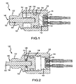
- Figure 1 is a cross-sectional view of an actuator system showing a movable element in a retracted position before activation.
- Figure 2 is a cross-sectional view of the actuator system showing the movable element in an extended position following activation.
- Figure 3 is a cross-sectional view of an alternative actuator system showing the movable element in the retracted position before activation.
- Figure 4 is a cross-sectional view of the alternative actuator system showing the movable element in the extended position following activation.
- various representative implementations of the present invention may be applied to any device for controlling blow-by in an actuator.
- a detailed description of an exemplary application, namely an actuator system, is provided as a specific enabling disclosure that may be generalized to any application of the disclosed system, device, and method for sealed actuators in accordance with various embodiments of the present invention.
- an actuator system 100 provides an actuator that facilitates movement while inhibiting unintended transfer of material past the actuator system 100.
- the actuator system 100 may be configured to contain gas blow-by generated by an explosive actuating device.
- the actuator system 100 comprises a housing 110, a sleeve 130, and a mover 150.
- the housing 110 contains the components of the actuator system 100.
- the sleeve 130 provides a movable interface between the mover 150 and a movable element 152 to be moved, such as a piston or rod.
- the mover 150 applies force to the sleeve 130 to move the sleeve 130.
- the housing 110 may comprise any suitable housing for containing the components of the actuator system 100, such as a metal, plastic, ceramic, or combination of materials. Additionally, the housing 110 may be configured in any suitable manner. In the present embodiment, the housing 110 comprises an interior wall 112, an open end 114 and a closed end 116. The housing 110 contains the sleeve 130 and the mover 150. The housing 110 is also suitably configured to contain gas or other contaminants that may be associated with the actuator system 100, such as gas and particles that may be generated by an explosive mover 150. In the present embodiment, the housing 110, the sleeve 130, and the movable element 152 are generally cylindrical, though any appropriate shape or configuration may be employed. In an alternative embodiment, an exterior surface of the housing 110 may be configured to engage a tool for manipulating the actuator system 100. For example, the exterior surface of the housing 110 may be hexagonal, for example to engage a wrench.
- the sleeve 130 responds to force applied by the mover 150 and transfers the force to and moves the movable element 152.
- the sleeve 130 is configured to maintain its integrity, i.e., inhibit development of perforations, breaks, or other openings that may allow the passage of contaminants, when the sleeve 130 responds to the force applied by the mover 150.
- an immobile portion of the sleeve 130 may be attached to the housing 110 to form a seal.
- the sleeve 130 may be configured in any suitable manner to transfer force and movement to the movable element 152.
- a portion of the sleeve 130 may be configured to slide along the interior wall 112 within the housing 110 upon activation of the mover 150.
- the sleeve 130 comprises a first end 132, a second end 134, and a deformable portion 136.
- the first end 132 remains immobile, and the second end 134 transfers movement force to the movable element 152.
- the deformable portion 136 deforms in response to force applied to the second end 134 to facilitate movement of the second end 134 and the movable element 152 with respect to the immobile first end 132.
- the first end 132 of the sleeve 130 is sealed, for example via a laser weld, an electron beam weld, a fusion weld, or the like, to the open end 114 of the housing 110 and/or a structure attached to the housing 110.
- the sealed connection between the first end 132 of the sleeve 130 and the housing 110 inhibits gas or other contaminants from entering or exiting the housing 110.
- the first end 132 of the sleeve 130 is detachably coupled to the open end 114 of the housing 110, for example using a threaded interface and a gasket or other sealable connection.
- the second end 134 of the sleeve 130 is configured to reside and move within the housing 110.
- An exterior portion 138 of the second end 134 of the sleeve 130 slidably engages the interior wall 112 of the housing 110.
- the outside diameter of the exterior portion 138 is suitably slightly less than the interior diameter of the interior wall 112 to guide the travel path of the second end 134 and restrict gas flow between the second end 134 of the sleeve 130 and the interior wall 112 of the housing 110.
- the sleeve 130 may comprise multiple elements.
- the sleeve 130 may comprise a first element 310 and a second element 312.
- the first element 310 forms the first end 132 and the second element 312 forms the second end 134.
- the first element 310 includes a hollow tube 314 disposed within an aperture formed in the second element 312.
- the hollow tube 314 suitably defines the deformable portion 136 of the sleeve 130.
- the sleeve 130 may also include a stop 316 between the second end 134 and the first end 132.
- the stop 316 suitably controls the compression of the sleeve 130 in response to the mover 150, such as to inhibit excessive compression of the sleeve 130 and/or to more smoothly decelerate the compression of the sleeve 130 as the compression nears completion.
- the stop 316 may be configured in any suitable manner to selectively control the compression of the sleeve 130.
- the present stop 316 comprises a skirt around the perimeter of the second end 134 and/or the second element 312. The material and/or structure of the skirt may be selected according to any suitable criteria to facilitate the deceleration and control of the sleeve 130 compression.
- the stop 316 may also be configured to avoid interfering with the collapse of the deformable portion 136. Further, the stop 316 may be configured to retain the sleeve 130 in the compressed position following compression.
- the skirt may include one or more catches formed on the exterior surface of the skirt that may engage notches in the interior surface 112 of the housing 110 upon compression to prevent re-expansion of the sleeve 130.
- the actuator system 100 may also include additional elements to inhibit fluid transfer between the exterior portion 138 and the interior wall 112.
- a seal such as a conventional resilient o-ring 144 or a viscous lubricant, may be disposed between the exterior portion 138 and the interior wall 112 to further restrict gas flow between the exterior portion 138 of the second end 134 of the sleeve 130 and the interior wall 112 of the housing 110.
- the deformable portion 136 of the sleeve 130 is configured to deform when sufficient force is applied against the sleeve 130.
- the deformation of the deformable portion 136 allows the second end 134 to move relative to the first end 132.
- the deformable portion 136 is configured to collapse by bending outward radially away from the movable element 152. By bending away from the movable element 152, the deformable portion 136 does not interfere with the movement of the movable element 152.
- the deformable portion 136 is suitably configured to bend without losing integrity of the material.
- the deformable portion 136 of the sleeve 130 provides stand-off for the actuator system 100, which allows pressure to build behind the second end 134 of the sleeve 130 before the deformable portion 136 starts to deform and the actuator system 100 begins to operate.
- the deformable portion 136 of the sleeve 130 may comprise any suitable material and be configured in any appropriate manner for bending without losing integrity.
- the deformable portion 136 may comprise a metal that is selectively softened around a selected area and geometrically configured to promote the desired collapse of the deformable portion 136 in a predetermined manner in response to force applied to the second end 134.
- the deformable portion may be softened by annealing, which may alter the strength of selected portions of a material by changing its microstructure, for example by heating and cooling the material.
- the metal deformable portion 136 may be configured to collapse and maintain the seal by annealing selected areas of the deformable portion 136, for example using a process of RF induction to band anneal selected areas around the sleeve 130.
- Any suitable form of annealing may be applied to form the deformable portion 136, such as laser annealing and/or electron beam annealing.
- Annealing increases the ductility of the metal to promote collapse upon application of a selected force. Annealing also facilitates selection a desired size for the deformable portion 136 of the sleeve 130 for particular applications requiring specific stroke lengths of the actuator system 100.
- the deformable portion 136 may be configured to deform upon application of a threshold amount of force. For example, the amount and extent of the annealing may be adjusted to affect the load sustainable by the deformable portion 136 prior to deforming.
- the physical structure of the deformable portion 136 such as the thickness of the material or the surface of the deformable portion 136, may be selected and/or modified to achieve a threshold force before deforming.
- the movable element 152 moves upon operation of the actuator system 100 and allows the actuator system 100 to be coupled to and/or apply force to other systems.
- the movable element 152 may comprise any suitable movable element for moving and applying force to other systems, and may be configured in any suitable manner and comprise any appropriate materials for achieving the relevant function.
- the movable element 152 comprises a substantially rigid rod disposed into the aperture 140 formed in the first end 132 of the sleeve 130 that passes through the deformable portion 136 of the sleeve 130 and into the second end 134 of the sleeve 130.
- the movable element 152 is suitably configured so that the exterior wall 154 of the movable element 152 slidably engages the interior wall 142 of the sleeve 130.
- the movable element 152 slidably engages the interior wall 142 of the sleeve 130 proximate the first end 132 and the deformable portion 136 of the sleeve 130.
- the movable elements 152 may abut the second end 134 of the sleeve 130.
- the movable element 152 may be configured to engage the interior wall 142 of the sleeve 130, for example via an annular protrusion extending radially from the surface of the movable element 152 and into a space formed between the end of the hollow tube 314 and the interior surface of the second element 312.
- the movable element 152 may also extend through the second element 312 to the second end 134.
- the seam between the movable element 152 and the second element 312 may be sealed, such as by weld material.
- the movable element 152 may be fixed in position, such as via welds between the annular protrusion and the end of the hollow tube 314 and/or the interior surface of the second element 312.
- the movable element 152 may extend from the first end 132 of the sleeve 130 when overall length of the sleeve 130 decreases when the mover 150 applies force to the second end 134.
- the movable element 152 may be fixed to the second end 134, for example via a laser weld, an electron beam weld, a fusion weld, or the like so that the movable element 152 remains connected to the sleeve 130 following actuation, or may abut the second end 134 so that the movable element 152 is released from the sleeve 130 following actuation, effectively shooting the movable element 152 out of the sleeve 130. Additionally, the movable element 152 may be omitted.
- the actuator system 100 may operate by changing the fluid pressure in a system proximate the first end 132 of the sleeve 130 by changing the volume in the system. No movable element 152 would be required, as the compression of the sleeve 130 and the volume defined by the interior wall of the sleeve 130 may be sufficient to cause changes in fluid pressure.
- the mover 150 applies force to the second end 134 of the sleeve 130 when the actuator system 100 is operated.
- the mover 150 may comprise any suitable mechanism for applying force to the second end 134.
- the mover 150 may comprise an explosive material and a detonating mechanism.
- the mover 150 comprises an explosive proximate an interior portion 118 of the closed end 116 of the housing 110.
- the explosive is connected to the detonating mechanism, such as wires for receiving an electrical signal, a fuse, or a percussion surface for receiving an impact.
- the mover 150 may comprise mechanical or hydraulic systems to apply force to the second end 134.
- the mover 150 is suitably sealed within the housing 110, for example to ensure increasing pressure upon detonation.
- the actuator system 100 begins operation with the deformable portion 136 fully extended.
- the mover 150 exerts force upon the second end 134 of the sleeve 130.
- the explosive may generate rapidly expanding gas, increasing gas pressure within the housing 110.
- the increased gas pressure applies force to the second end 134 of the sleeve 130, which transfers the force along the length of the sleeve 130.
- the deformable portion 136 begins to deform and the second end 134 begins to move.
- the second end 134 pushes the movable element 152 out of the sleeve 130.
- the deformable portion 136 of the sleeve 130 collapses into a cavity that may operate as a containment area 146 between the sleeve 130 and the housing 110.
- the containment area 146 may receive and retain any gas blow-by that may flow between the exterior portion 138 of the second end 134 of the sleeve 130 and the interior wall 112 of the housing 110.
- the seal between the first end 132 and the housing 110 and the surface of the deformable portion 136 retains the gas in the housing 110.
- any method or process claims may be executed in any order and are not limited to the specific order presented in the claims.
- the components and/or elements recited in any apparatus claims may be assembled or otherwise operationally configured in a variety of permutations to produce substantially the same result as the present invention and are accordingly not limited to the specific configuration recited.
Landscapes
- Engineering & Computer Science (AREA)
- Physics & Mathematics (AREA)
- Fluid Mechanics (AREA)
- Mechanical Engineering (AREA)
- General Engineering & Computer Science (AREA)
- Chemical & Material Sciences (AREA)
- Analytical Chemistry (AREA)
- Actuator (AREA)
Claims (14)
- Système d'actionnement (100), comprenant :un carter (110), comprenant :une paroi intérieure (112) ; etune extrémité ouverte (114) ;un manchon (130), comprenant :une première extrémité (132 ; 310), comprenant une partie extérieure scellée à l'extrémité ouverte du carter ;une seconde extrémité (134 ; 312), comprenant une partie extérieure (138) configurée pour coulisser le long de la paroi intérieure du carter en réponse à l'application d'une force de seuil sélectionnée ; etune partie déformable (136 ; 314) située entre la première extrémité et la seconde extrémité et configurée pour se déformer en réponse à l'application de la force de seuil sélectionnée ; etun élément propulseur (150) engrenant la seconde extrémité du manchon et configuré pour appliquer la force de seuil sélectionnée à la seconde extrémité du manchon, dans lequel la force de seuil sélectionnée provient de l'intérieur du carter et provoque la déformation.
- Système d'actionnement (100) selon la revendication 1, dans lequel la partie déformable (136 ; 314) du manchon (130) comprend une partie d'une surface extérieure du manchon définissant au moins une partie d'une cavité (146).
- Système d'actionnement (100) selon la revendication 1, dans lequel le carter (110) et le manchon (130) définissent une cavité (146) placée entre la première extrémité (132 ; 310) et la seconde extrémité (134 ; 312) du manchon.
- Système d'actionnement (100) selon la revendication 1, dans lequel l'élément propulseur (150) comprend un explosif.
- Système d'actionnement selon la revendication 1, dans lequel le carter (110) est sensiblement cylindrique et comprend :une extrémité fermée ;dans lequel le manchon (130) est sensiblement cylindrique et a un intérieur creux ;dans lequel la première extrémité (132 ; 310) définit une partie d'une cavité (146) ;dans lequel la seconde extrémité (134 ; 312) définit une partie de la cavité ; etdans lequel une surface de la partie déformable (136 ; 314) définit une partie de la cavité ;comprenant en outre un élément mobile (152) disposé à l'intérieur de l'intérieur creux du manchon ; etdans lequel l'élément propulseur (150) est un explosif disposé à l'intérieur du carter à côté de la seconde extrémité du manchon et configuré pour appliquer la force de seuil à la seconde extrémité du manchon.
- Système d'actionnement selon la revendication 1 ou 5, dans lequel :la partie déformable (136 ; 314) comprend un cylindre ayant un axe longitudinal ; etla partie déformable est configurée pour fléchir dans le plan radial en s'écartant de l'axe longitudinal.
- Procédé de déplacement d'un élément (152), comprenant :la mise à disposition d'un carter (110), comprenant :une paroi intérieure (112) ; etune extrémité ouverte (132 ; 310) ;la mise à disposition d'un manchon (130) ayant un intérieur creux et recevant l'élément, comprenant :une première extrémité (132 ; 310) comprenant une partie extérieure scellée à l'extrémité ouverte du carter ;une seconde extrémité (134 ; 312) coulissant le long de la paroi intérieure du carter en réponse à l'application d'une force de seuil sélectionnée ; etune partie déformable (136 ; 314) située entre la première extrémité et la seconde extrémité ;l'application de la force de seuil sélectionnée depuis l'intérieur du carter sur la seconde extrémité du manchon ; etla déformation de la partie déformable en réponse à l'application de la force de seuil sélectionnée.
- Procédé selon la revendication 7, comprenant en outre la mise à disposition d'une cavité (146) à l'intérieur du carter (110) pour recevoir un gaz perdu passant entre la seconde extrémité (134 ; 312) du manchon (130) et la paroi intérieure (112) du carter.
- Système selon l'une quelconque des revendications 1 à 6 ou procédé selon la revendication 7, dans lequel la partie déformable (136, 314) comprend un métal adouci de manière sélective.
- Système selon l'une quelconque des revendications 1 à 6 ou procédé selon la revendication 7, dans lequel la partie déformable (136 ; 314) comprend un matériau recuit.
- Système ou procédé selon la revendication 10, dans lequel le matériau recuit est recuit en bandes.
- Système ou procédé selon la revendication 10, dans lequel le matériau recuit est recuit par induction.
- Système ou procédé selon la revendication 10, dans lequel le matériau recuit est recuit par induction de RF.
- Procédé selon la revendication 7, dans lequel la déformation de la partie déformable (136 ; 314) comprend la flexion de la partie déformable dans le plan radial en s'écartant d'un axe longitudinal du manchon (130).
Applications Claiming Priority (2)
| Application Number | Priority Date | Filing Date | Title |
|---|---|---|---|
| US11/420,361 US7634912B2 (en) | 2006-05-25 | 2006-05-25 | Methods and apparatus for actuator system |
| PCT/US2007/069422 WO2008105885A2 (fr) | 2006-05-25 | 2007-05-22 | Procédés et appareils pour système d'actionnement |
Publications (3)
| Publication Number | Publication Date |
|---|---|
| EP2019909A2 EP2019909A2 (fr) | 2009-02-04 |
| EP2019909A4 EP2019909A4 (fr) | 2010-03-31 |
| EP2019909B1 true EP2019909B1 (fr) | 2013-12-18 |
Family
ID=38748245
Family Applications (1)
| Application Number | Title | Priority Date | Filing Date |
|---|---|---|---|
| EP07873819.2A Active EP2019909B1 (fr) | 2006-05-25 | 2007-05-22 | Procédés et appareils pour système d'actionnement |
Country Status (4)
| Country | Link |
|---|---|
| US (1) | US7634912B2 (fr) |
| EP (1) | EP2019909B1 (fr) |
| JP (1) | JP2009538406A (fr) |
| WO (1) | WO2008105885A2 (fr) |
Families Citing this family (4)
| Publication number | Priority date | Publication date | Assignee | Title |
|---|---|---|---|---|
| US7709433B2 (en) | 2007-02-12 | 2010-05-04 | S.C. Johnson & Son, Inc. | Self-sticking disintegrating block for toilet or urinal |
| FR2938884B1 (fr) * | 2008-11-26 | 2013-02-08 | Snpe Materiaux Energetiques | Verin a course declenchee pour dispositif de securite integre a un vehicule automobile, pour la protection d'un pieton en cas de choc frontal |
| CN105658486B (zh) * | 2013-09-30 | 2018-06-01 | Tk控股公司 | 烟火式致动器 |
| US10222189B2 (en) * | 2016-07-22 | 2019-03-05 | Raytheon Company | Stage separation mechanism and method |
Family Cites Families (6)
| Publication number | Priority date | Publication date | Assignee | Title |
|---|---|---|---|---|
| US3234727A (en) * | 1964-11-04 | 1966-02-15 | Ncr Co | Explosive motors |
| US4111221A (en) * | 1976-01-28 | 1978-09-05 | Olsen Charles R | Low restriction, normally open valve construction having a deformable bladder |
| JPS56116056U (fr) * | 1980-02-04 | 1981-09-05 | ||
| PL185374B1 (pl) * | 1998-01-19 | 2003-04-30 | Lagodzinska Boguslawa | Samorepetujący osadzak wybuchowy |
| DE20102758U1 (de) * | 2001-02-16 | 2001-06-28 | TRW Occupant Restraint Systems GmbH & Co. KG, 73553 Alfdorf | Gurtstraffer |
| FR2878212B1 (fr) | 2004-11-22 | 2008-08-29 | Pyroalliance Sa | Systemes d'absorption mecaniques pour articulation active de capot |
-
2006
- 2006-05-25 US US11/420,361 patent/US7634912B2/en active Active
-
2007
- 2007-05-22 EP EP07873819.2A patent/EP2019909B1/fr active Active
- 2007-05-22 WO PCT/US2007/069422 patent/WO2008105885A2/fr active Application Filing
- 2007-05-22 JP JP2009512256A patent/JP2009538406A/ja active Pending
Also Published As
| Publication number | Publication date |
|---|---|
| EP2019909A4 (fr) | 2010-03-31 |
| JP2009538406A (ja) | 2009-11-05 |
| WO2008105885A3 (fr) | 2008-12-11 |
| US7634912B2 (en) | 2009-12-22 |
| EP2019909A2 (fr) | 2009-02-04 |
| US20070271922A1 (en) | 2007-11-29 |
| WO2008105885A2 (fr) | 2008-09-04 |
Similar Documents
| Publication | Publication Date | Title |
|---|---|---|
| EP2019909B1 (fr) | Procédés et appareils pour système d'actionnement | |
| US20060169132A1 (en) | Linear hydraulic actuator | |
| EP1548322B1 (fr) | Amortisseur | |
| WO2008112332A4 (fr) | Vanne d'étranglement ou de réglage sur conduite | |
| JPH06213202A (ja) | 油圧増圧器 | |
| US3831919A (en) | Telescopic gas springs | |
| US6913126B2 (en) | Impact damper | |
| JP3993587B2 (ja) | 可変押圧作動型火薬式アクチュエータ | |
| US11293463B2 (en) | Externally verifiable thermal compensation of cowl opening actuator | |
| KR102057268B1 (ko) | 안전장치를 포함하는 압축성 유체 장치 및 압축성 유체 장치 보호 방법 | |
| EP2205375B1 (fr) | Bouteille à gaz à arrêt commandé | |
| JP2007263129A (ja) | 速度応答型エアーダンパー | |
| JP3726930B2 (ja) | アクチュエータ | |
| US6655143B2 (en) | Autonomous gas powered ram | |
| JP2008309179A (ja) | 油圧緩衝器 | |
| KR20220080704A (ko) | 전환밸브 | |
| JP2810165B2 (ja) | 二段作動ステーダンパ | |
| DE102016218684A1 (de) | Ventil zum Schließen einer Fluidleitung | |
| JP4898623B2 (ja) | バルブ装置 | |
| JP4804474B2 (ja) | 推力を制御可能で且つ形状が最適化された点火式アクチュエータ | |
| US3588076A (en) | Variable-orifice device | |
| US20040128998A1 (en) | Autonomous gas powered ram | |
| JP4890414B2 (ja) | バルブ装置 | |
| JP2023117255A (ja) | アクチュエータ | |
| JP5142958B2 (ja) | 緩衝器 |
Legal Events
| Date | Code | Title | Description |
|---|---|---|---|
| PUAI | Public reference made under article 153(3) epc to a published international application that has entered the european phase |
Free format text: ORIGINAL CODE: 0009012 |
|
| 17P | Request for examination filed |
Effective date: 20081112 |
|
| AK | Designated contracting states |
Kind code of ref document: A2 Designated state(s): AT BE BG CH CY CZ DE DK EE ES FI FR GB GR HU IE IS IT LI LT LU LV MC MT NL PL PT RO SE SI SK TR |
|
| AX | Request for extension of the european patent |
Extension state: AL BA HR MK RS |
|
| DAX | Request for extension of the european patent (deleted) | ||
| RBV | Designated contracting states (corrected) |
Designated state(s): DE FR GB IT |
|
| A4 | Supplementary search report drawn up and despatched |
Effective date: 20100226 |
|
| GRAP | Despatch of communication of intention to grant a patent |
Free format text: ORIGINAL CODE: EPIDOSNIGR1 |
|
| INTG | Intention to grant announced |
Effective date: 20130523 |
|
| GRAS | Grant fee paid |
Free format text: ORIGINAL CODE: EPIDOSNIGR3 |
|
| GRAA | (expected) grant |
Free format text: ORIGINAL CODE: 0009210 |
|
| AK | Designated contracting states |
Kind code of ref document: B1 Designated state(s): DE FR GB IT |
|
| REG | Reference to a national code |
Ref country code: GB Ref legal event code: FG4D |
|
| REG | Reference to a national code |
Ref country code: DE Ref legal event code: R096 Ref document number: 602007034371 Country of ref document: DE Effective date: 20140213 |
|
| REG | Reference to a national code |
Ref country code: DE Ref legal event code: R097 Ref document number: 602007034371 Country of ref document: DE |
|
| PLBE | No opposition filed within time limit |
Free format text: ORIGINAL CODE: 0009261 |
|
| STAA | Information on the status of an ep patent application or granted ep patent |
Free format text: STATUS: NO OPPOSITION FILED WITHIN TIME LIMIT |
|
| 26N | No opposition filed |
Effective date: 20140919 |
|
| REG | Reference to a national code |
Ref country code: DE Ref legal event code: R097 Ref document number: 602007034371 Country of ref document: DE Effective date: 20140919 |
|
| REG | Reference to a national code |
Ref country code: FR Ref legal event code: PLFP Year of fee payment: 10 |
|
| REG | Reference to a national code |
Ref country code: FR Ref legal event code: PLFP Year of fee payment: 11 |
|
| REG | Reference to a national code |
Ref country code: FR Ref legal event code: PLFP Year of fee payment: 12 |
|
| P01 | Opt-out of the competence of the unified patent court (upc) registered |
Effective date: 20230530 |
|
| PGFP | Annual fee paid to national office [announced via postgrant information from national office to epo] |
Ref country code: GB Payment date: 20240419 Year of fee payment: 18 |
|
| PGFP | Annual fee paid to national office [announced via postgrant information from national office to epo] |
Ref country code: DE Payment date: 20240418 Year of fee payment: 18 |
|
| PGFP | Annual fee paid to national office [announced via postgrant information from national office to epo] |
Ref country code: IT Payment date: 20240418 Year of fee payment: 18 Ref country code: FR Payment date: 20240418 Year of fee payment: 18 |